1. Introduction
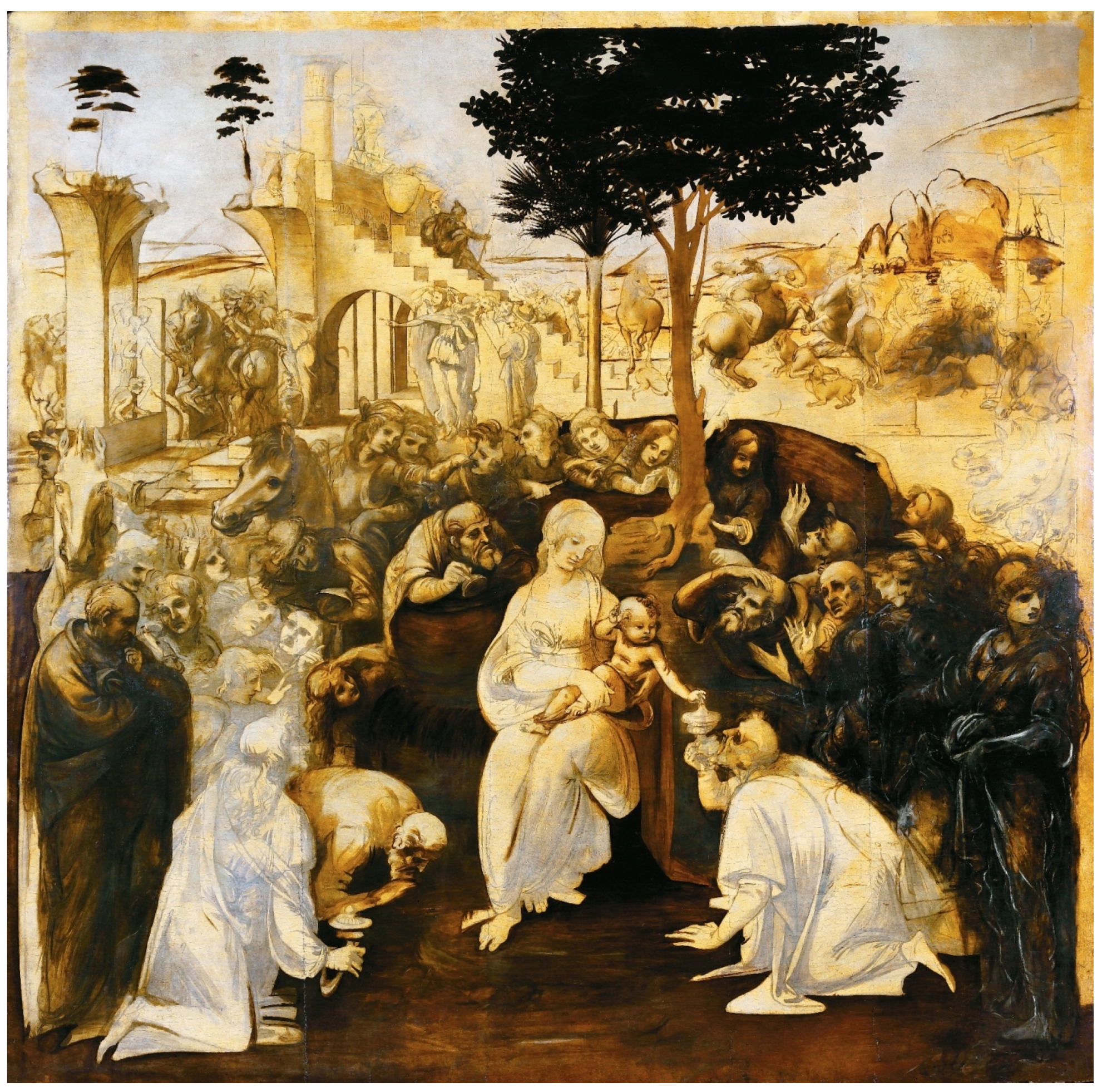
In 1481, the Augustinian monks at San Donato in Scopeto, near Florence, commissioned Leonardo da Vinci to paint an
Adoration of the Magi [
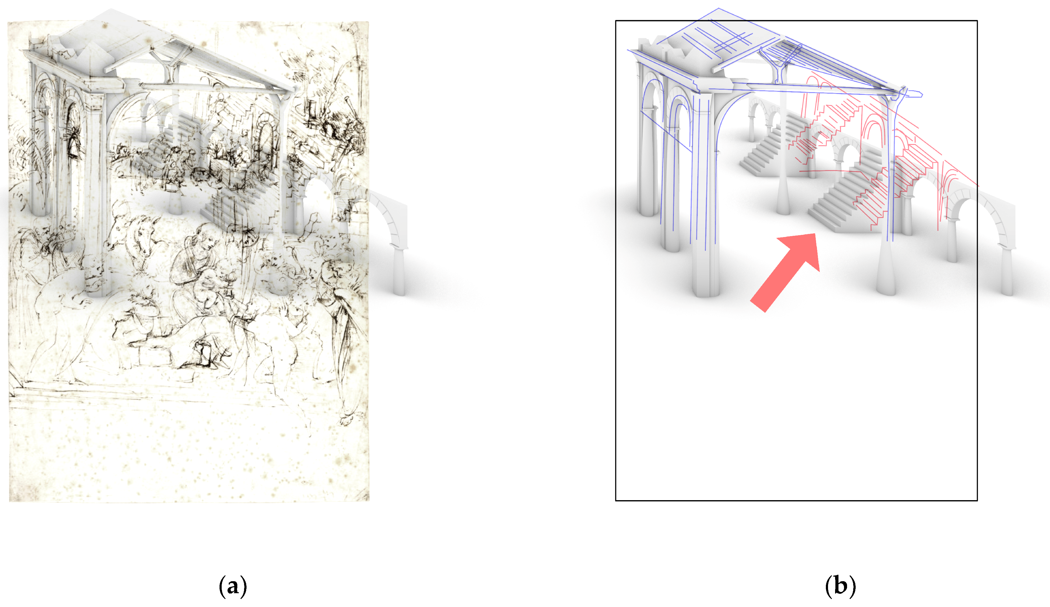
1], which has since been unanimously identified by experts as the panel that is now at the Gallerie degli Uffizi in Florence. The painting is on a panel that was originally supposed to be a square, 244 cm long on each side, which the Italian Renaissance artist left unfinished upon his departure to Milan (
Figure 1). The commission was then handed over to Filippino Lippi, who completed his version of the
Adoration in 1496. Today, this painting is also housed in the Gallerie degli Uffizi. The theme of the Adoration of the Magi is set within the context of the celebration of the Feast of Epiphany in which, according to St. Augustine, all peoples respond to the call of Christ. Leonardo sketched out a very complex composition, rich in figures, organized in a semicircle, with the Virgin and Child as its fulcrum. The Magi kneel in front of them, bringing gold, frankincense, and myrrh as gifts to Jesus. Leonardo paints a background in which crumbling architecture, collisions of horses, riders, worshipers, and curious onlookers jostle for position; on the left, there is the construction site of some kind of building, perhaps a temple, preceded by two flights of stairs like the presbytery of some medieval churches (e.g., San Miniato al Monte in Florence). The temple, an allusion to peace, is in stark contrast to the melee of knights in combat depicted on the opposite side.
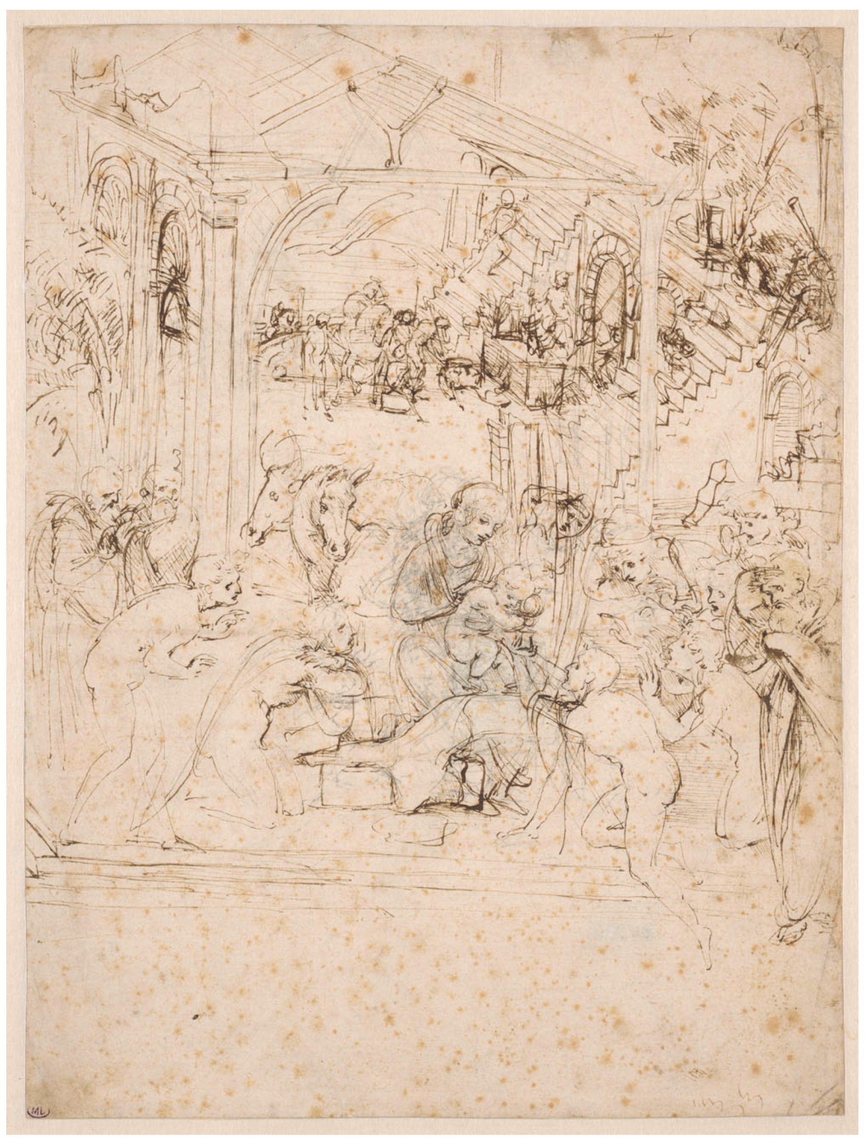
Today, several preparatory drawings for the unfinished painting by Leonardo remain, among which the two most famous are certainly the two depicting the
Adoration of the Magi (1481, pen and brown ink over lead-point tracing on paper, 284 × 213 mm, Paris, Musée du Louvre, Département des Arts Graphiques, R.F. 1978) (
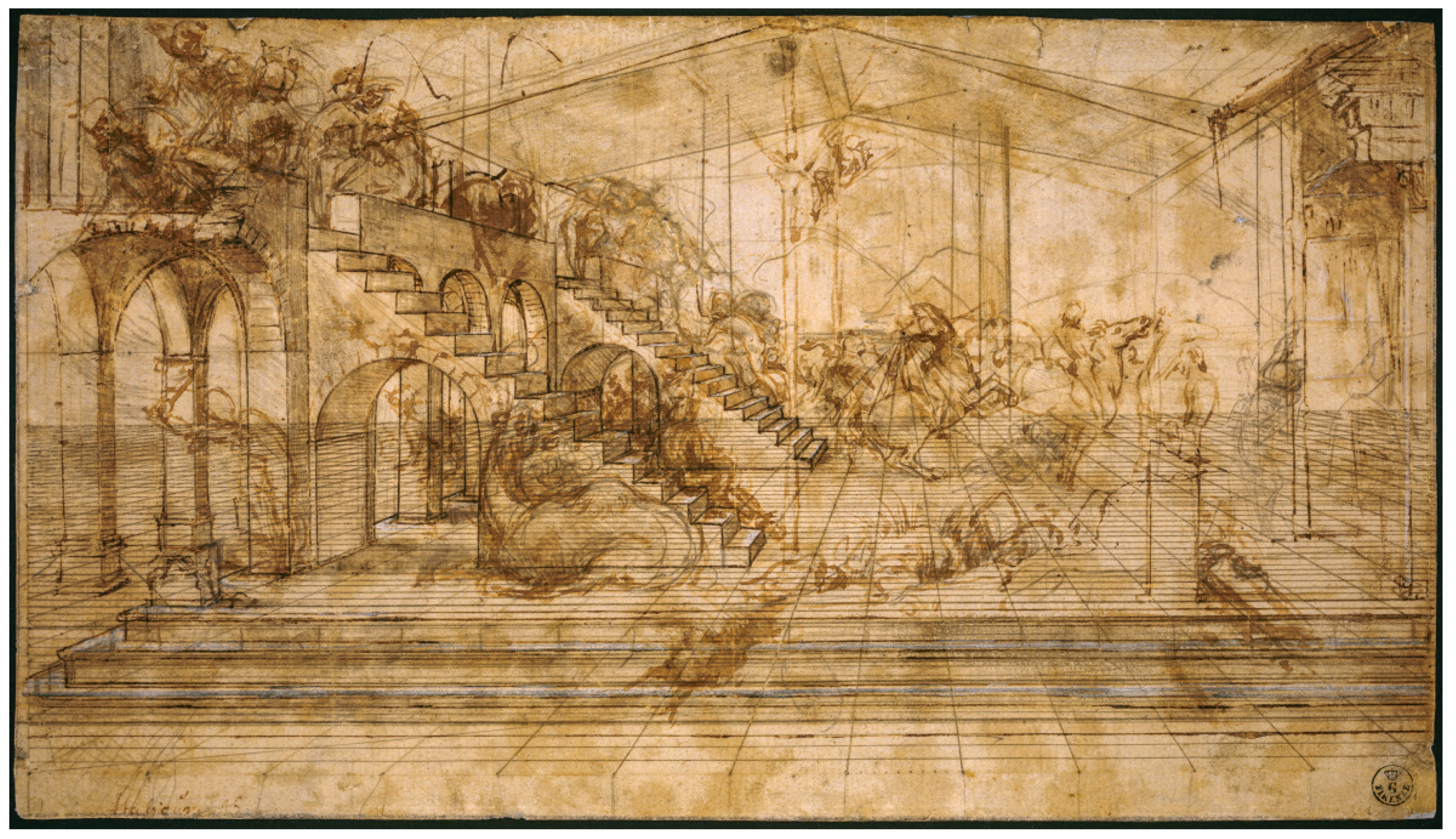
Figure 2) and the
Study for the Background of the Adoration of the Magi (around 1481, metal point, reworked with pen and iron-gall ink, diluted iron-gall ink, partially oxidized white gouache highlights (basic lead carbonate), stylus and compass, on light brown prepared paper, 164 × 290 mm, Florence, Le Gallerie degli Uffizi, GDSU, inv. 436 E) (
Figure 3) [
2,
3,
4]. These are preserved at the Louvre and the Uffizi, respectively; critics have long since grouped them in connection with the painting commissioned from Leonardo for the high altar of the convent church of San Donato in Scopeto. In these drawings, Leonardo depicted the architecture that appears in the upper part of the unfinished painting at the Uffizi. They are an invaluable source for understanding not only the painting but also the architectural context where the not yet thirty-year-old Leonardo lived, as well as his way of conceiving and presenting the architecture to the observer.
Some of the motifs appearing in the preparatory drawing held at Louvre (
Figure 2) are also present in the preparatory drawing held at Uffizi (
Figure 3), but they have been mirrored to the other side (i.e. the double flight of stairs, the battling horsemen, and the people occupying the steps and the terrace). The Louvre drawing presents a design still in the process of radical reworking, one that is very different from the perspective study at the Uffizi that was scrupulously finished and calculated concerning its outcome. Furthermore, among the preparatory drawings for the
Adoration that have survived, only the Louvre representation frames the whole composition, and this is certainly a preparatory work in a very preliminary sense, representing an early stage in his inventive process.
As has already been argued several times, the two drawings correspond with two different moments in the conception of the work. The first sheet presents an initial imagining of the overall composition, while the second one focuses on a detailed study that is rather closer to the eventual solution adopted in the background of the painting. Although the Louvre drawing reflects an early stage in the compositional arrangement, it could also be read as a work in anticipation of the drawing for the background preserved at the Uffizi. That later drawing is much more precise in its indication of perspective, and it is meticulously delineated, with a dense web of lines and vanishing points; furthermore, it is often considered to be the last of the studies for the corresponding part of the final painting [
5].
The differences between the two preparatory drawings explain the discrepancies, also present in the painting, between the compositional structure of the foreground, where the representation of the figures does not closely adhere to the rules of linear perspective, and the background, which, on the contrary, is organized according to accurate rules of perspective.
As mentioned by Marzia Faietti, we must consider the two preparatory studies as belonging to a completely coherent succession, according to the evolution of Leonardo’s creative process. The artist conceived a different perspective view, dividing the foreground from the background in the painting, but this was only after analyzing the elements of the work and the general composition of the Parisian sheet, where there is still no clear divergence in the criteria of representation between the figures in the foreground and the buildings in the background: “Una volta, compresa la necessità di una forte cesura tra i diversi registri narrativi, fu allora possibile per Leonardo studiare in dettaglio singole parti del dipinto. Intervenne così il disegno prevalentemente di studio architettonico degli Uffizi dove paiono di gran lunga superate le incertezze prospettiche dello studio d’insieme al Louvre” [
6] (i.e., “Once he comprehended the necessity to use very different narrative styles, it became possible for Leonardo to start studying in detail each separate element of the painting. That is when the (mainly) architectural study drawing at the Uffizi was developed. In this drawing, the perspective uncertainties of the previous study, held in the Louvre, seem to have been overcome”).
In this paper, we will focus on the Louvre drawing, expand upon Marzia Faietti’s comments, and clarify Leonardo’s starting point when designing the future painting.
Our starting points are in general the countless number of works dedicated to the painting and more specifically to the drawing, and to analyze in detail the observation by Martin Kemp concerning the background: “The frieze of figures, already animated by an unusual intensity of reaction, is reasonably coherent (if somewhat over-weighted to the right), but the complex background has been arbitrarily inserted at a disconcerting angle and with an awkwardly high viewpoint. His intention in adding the background scene is clear; he was aiming for that combination of classical ruins and processional clamor familiar from Filippo’s
Adoration” [
7].
The building that is apparently in ruins, but that is under construction (or rather: under reconstruction or restoration), is the only detail present in both studies. It is located on the right in the Louvre’s drawing and on the left in the Uffizi’s drawing and painting, and it represents the main element for understanding the iconological substratum of the work.
This “complex background … arbitrarily inserted at a disconcerting angle and with an awkwardly high viewpoint”, in our opinion was widely illustrated from the point of view of the subject represented (architectural ruins or in construction artifacts) (e.g., in [
4,
8]) but, as far as we know, it has never been carefully analyzed by scholars; in any case, it has never been the object of accurate explanations concerning the representation technique.
Thus, rather than following the usual research path based on the reconstruction of the work’s development, based on the close collaboration between the artist and his patron and the identification of the subject represented from literal, artistic, or true references, our study focuses only on the architectural elements of the scene as solid elements that are a result of the drawing technique that Leonardo used. In this sense, the work is complementary to our recent study on the Uffizi drawing that revealed a new point of view regarding Leonardo’s way of conceiving perspective in his drawings [
9]. The work presented here is intended as a continuation of this research route.
From the point of view of the represented architecture, we can observe a roofed structure on the left, a structure with stairs on the right, a damaged (or under construction) wall and pillar right behind the human characters in the foreground, and a destroyed arc at the top right corner. The most interesting architectural elements on which we will focus our attention are the roofed structure and the structure with stairs.
Our analysis will focus on the construction of the perspective of the scene, starting from two observations.
The first is made by Pierre Francastel: “Renaissance architecture was painted before it was built”. [
10] (p. 70). The crucial role that architecture plays, both as an instrument for organizing the composition and as an element carrying iconographic meaning, remains to be completely clarified. The organization of the scene affects a contrast between the monumental structure in ruins and the humble shed of the Nativity, reinterpreting an iconographical theme that was widespread at the time [
8]. In this sense, the architectural representation allows the understanding of the artist’s intent. Based on these observations, new insights on Leonardo’s drawing and composition technique are possible.
The second one concerns the technique used for the construction of perspective. When Leonardo da Vinci began his apprenticeship at Verrocchio’s workshop between 1469 and 1470, two works by Leon Battista Alberti circulated in the painters’ practice, the
Elementa Picturae and
De Pictura, both written in Florence between 1435 and 1436 [
11], in which not only were theoretical and practical references given for the entire making of a painting but, above all, they fully show the best way (“modo optimo”, in Alberti’s words) to create representations exploiting perspective projection as a basic technique, that is, to put it in Leonardo’s words, to use the technique that was at the heart of the painting: “La pittura è fondata sulla prospettiva. Prospettiva non è altro che sapere bene figurare lo uffizio dell’occhio, (4-4)
1 il quale offizio s’astende solo in pigliare per [p]iramide le forme e colori di tutti li obietti contra sé posti” [
12] (i.e., “The art of painting is based on perspective. Perspective is nothing more than knowing exactly the function of the eye (4-4)
1, its function simply consists of receiving in a pyramid the forms and colors of all the objects placed before it”).
In daily practice, these texts were interpreted autonomously by each artist to put into practice the general descriptions of Alberti, filling in the holes of his general theory [
13]. However, most of the rules that we still use today were already established: convergence to the main point of the lines perpendicular to the picture plane, a horizon line at the height of a point of view generally matching the height of the human eye, conservation of true dimensions on the picture plane, construction on the ground plane, usually using a straight line at a 45° angle to determine the reduction coefficients of the measures as the depth increases, and parallelism to the horizon line of the projection of the lines, parallel to the picture plane.
The investigation method adopted to recompose the complex puzzle of Leonardo’s Adoration in the Louvre consists of the exploitation of 3D models that could accurately reconstruct the buildings, the working and representation methods, the hypothesized physical and cultural contexts trying to unravel Leonardo’s thoughts on architecture.
We reconstructed the 3D space of the architectural artifacts, drawn as 2D projections by the artist, with the use of the rules of the perspective as a central projection, those known by Leonardo and those focused on later. The development of a tailored technique for the analysis of the architectural artifacts, sketched in Leonardo’s Adoration, through their hypothetical 3D reconstruction is particularly useful, since it could also be extended to other Renaissance perspective case studies, as they are all made using Alberti’s treatises. The main issues that one must consider when dealing with the reconstructive process of Leonardo’s artifacts are the problems that one usually faces in any similar perspectival process.
In the end, we will not give ultimate results, which would require art history proofs and, specifically, a wide knowledge of Leonardo’s period; however, our claim is supported by unambiguous facts that can be observed directly in the drawing, which might encourage new and more extensive research in this direction. The main outcome consists of demonstrating that the Louvre drawing is an assemblage of many separate parts, each conceived individually, and that the whole scene is probably the result of initial inspiration from other paintings or drawings (by Leonardo himself or by other artists) in addition to the well-known examples of the
Adoration of the Magi painted by other artists in the same years of Leonardo’s work: the tempera painting on wood (111 × 134 cm) by Leonardo’s friend Sandro Botticelli, datable to around 1475, today in the Galleria degli Uffizi in Florence; the tempera painting on wood (70 × 103 cm), again by Sandro Botticelli and datable to around 1482 (the same period of Leonardo’s painting), today at the National Gallery of Art in Washington; the so-called
Tondo Cook, a tempera painting on wood (diameter 137.2 cm), today at the National Gallery of Art in Washington, that was begun by Beato Angelico and completed by Filippo Lippi [
14]. All these
Adorations exploit images of ruined Roman architecture for symbolic purposes—the fall of the old order and the birth of the new—but references are partial, and their number is surely greater.
2. The Louvre Adoration Drawing
The study for the
Adoration of the Magi, today at the Musée du Louvre in Paris, is an A4-sized paper sheet (28.3 × 21.3 cm) with line strands, evenly spaced at about 3.7 cm apart (
Figure 2). The sheet is cut slightly diagonally at the edges, indicating that it was probably trimmed. The wire rods are 11 to 12 per cm. All these features are hallmarks of a good quality paper but one that is probably not treated, as is the one used in the presentation drawings. This suggests that the drawing was intended for study.
Leonardo first used the lead point to draw, then redrew over some of the marks with a pen and iron-gall ink, while other marks remain traced with the lead point. For example, preparatory drawing in lead-point can be seen in the group of spectators on the right and in several elements in the background and the forward flight of stairs, the central structure at the roof level, and the tree trunks supporting the roof. The tracing process and the drawing development, despite a considerable number of studies, have never been analyzed in depth or clarified in the many writings on the drawing that, instead, mainly focus on an analysis of the subjects depicted, e.g., [
15,
16,
17,
18].
The paper sheet has been used for drawing both on the front and the back. We will focus on the front.
The composition is conceived in two distinct parts: in the foreground, the Virgin and Child are represented in an arc of worshipers. Most of the organization will be preserved in the final painting: the centrality of the Virgin and the Child, with the worshipers on both sides, an architectural structure with a double staircase railing on one side of the background, the procession of the Magi visible at the bottom. A poorly repaired, dilapidated building, the stable in Bethlehem, is installed at the center on a platform accessed by three steps.
The Virgin is identified through the technique, common in Leonardo’s work, of gradually exploring an idea by moving a figure around an axis, experimenting with three—perhaps four—different positions for the head and the legs [
5]. The foreground is complete with worshipers on both sides of the Virgin and the Child. The distance between the main group and the circle of visitors is smaller than in the painting.
From the architectural point of view, as well as in the painting and the Uffizi’s drawing, two cores clearly emerge, which imply in turn a conceptual twin: the mighty building in ruins and the hut of the Nativity. Overall, we can see the polarization of the scene as a very precise combination: on one side, the magnificent building on the right, and on the other side, the extraordinary complex in the center, in which the hut “joins” with classical architecture. This solution recalls the minor earlier or coeval works of Botticelli or Filippino but, at the same time, it stands out for its specific originality in the method of composing new and old elements.
The scene is arranged around the complex hut/classical architecture, which is off-center. That unevenness pushes the entire foreground to the right and, when combined with the composition’s high viewpoint, creates a diagonal perspective. The figures occupying the foreground are positioned on a three-step platform that closes off the composition along the front, with an interruption on the left by a corner.
This main structure consists of antique architectural ruins, as demonstrated by the crumbling wall above the entablature, to which is added vegetation at the basement level. It coexists in relationship with the sumptuous architecture on the right side of the drawing and exhibits an equally marked classicist language. This building integrates an old-fashioned front to the hut that makes a humble building, as the ramshackle wooden structure suggests, become the dominant element of the scene. The modest hut of the Nativity, sustained by supports like the one in the painting (i.e., a tree trunk with a fork termination), seems to lean against the derelict structure. On the left can be seen a square pillar and an arcature, supported by columns with decorated tympana. Part of an arch at right-angles to the square pillar at the forward corner can also be made out. In the lateral arches, marks are radiating from the center in a fan shape, which could have been traced to render the motif of the grooves of a shell valve, or more probably to indicate a blind arch or a niche. It is a decorative theme, with typically antiquarian (as well as early Christian) values, that has a particular resonance in contemporary artistic production [
8].
Other lead-point marks could depict different solutions for the roof and the classical ruined building, but it is impossible at present to produce reliable hypotheses.
In the right background, there is the second magnificent antique building structure (diagonally placed), a portico with arches on pillars that is specularly arranged in the painting. In front of the three central arches—which open in the same way as in the painting—between the two symmetrical ramps, there is a block like a sacrificial altar, its presence alluding to a temple [
19]. All around this main nucleus, sparse fragments of walls can be recognized, evoking a collapse, rather than a status of abandonment, linked to the passing of the centuries. The monument is characterized by double-flight staircases, perpendicular to the front (probably references to the Temple of Divus Claudius on the Caelian Hill in Rome) and by the external altar [
20].
The architectural elements composing the architectural backdrop of the Louvre drawing are therefore threefold: two pieces of ancient buildings—on the left and on the right—and the wooden hut at the center. This motif imposes itself visually and hierarchically on the first two: in fact, the right pitch of the roof of the temporary and humble hut covers part of the ramps, which we imagine as built from valuable stone blocks [
19].
Regarding the link between the hut and the classical ruined architecture, in our opinion, the most convincing interpretation is by Emanuela Ferretti [
8]. She addressed the symbolic aspects inherent in the architecture of the Louvre’s
Adoration, along with a marked Vitruvianism in the preparatory drawing of the Louvre, where she recognized the myth of the humble hut as a sign of the birth of civilization [
21] (bk. II, 1, 3), and the wooden origin of the Doric entablature [
21] (bk. IV, 2, 2) the connection between wooden architecture and stone architecture, such as the visual rendering, or rather its crystallization on the sheet of paper, of the petrifaction process undergone by the wooden parts of the structure supporting the roof. Furthermore, she proposed two different interpretations of the meaning of the ruined buildings, the structure with arcades and the perpendicular staircases, suggesting that the building could be either an ancient Roman monument or a representation of the Temple of Solomon. Both interpretations are plausible and fit with the current state of knowledge in the literature.
The inclusion of classical elements in the background, in Leonardo’s work as in those of other Italian Renaissance artists, goes beyond cultural or esthetic necessity [
22]. The proportions of the architectural orders and the spaces of classical monuments mainly support the perception of perspective space [
23], following the methods expounded by Alberti, with the practical implementation by Piero della Francesca of his
De Prospectiva Pingendi [
24]. The communicative power of a painting was strengthened when using ancient structures. In all three cited representations of the
Adoration of the Magi by Leonardo, the link between Christian religiosity and the “dream of the Antique” in the painted architecture not only demonstrates his fluency in classical language but also serves to give a perspectival structure to the space. Finally, as quoted by Emanuela Ferretti [
8], the inclusion of classical elements contributes decisively to emphasizing the message of the works through images that painters and patrons recognize in paintings.
3. Analysis of the Representation Technique
In this section, the marks traced by Leonardo are analyzed to extrapolate the plausible drawing process and the construction rules used to achieve the final representation of the depicted architectural structures. This first reconstruction step is propaedeutic to the 3D modeling of the scene and allows us to understand the geometric and projective features of the perspective used by the draftsman (i.e., the position of the point of view and the projection plane in 3D space). It consists of inversely projecting the vanishing point/s (in this case, the center of vision/s) of the 2D drawn perspective back into 3D space, using it/them to reconstruct the measurements and directions of the main architectural structures as a means to accurately model their elements and their position within the space. The smaller architectural elements in a state of ruin are not considered in this phase (e.g., the partially destroyed arc on the top right corner, the ruined wall on the right, and the damaged pillar in the middle).
3.1. Extrapolation of Vanishing Points
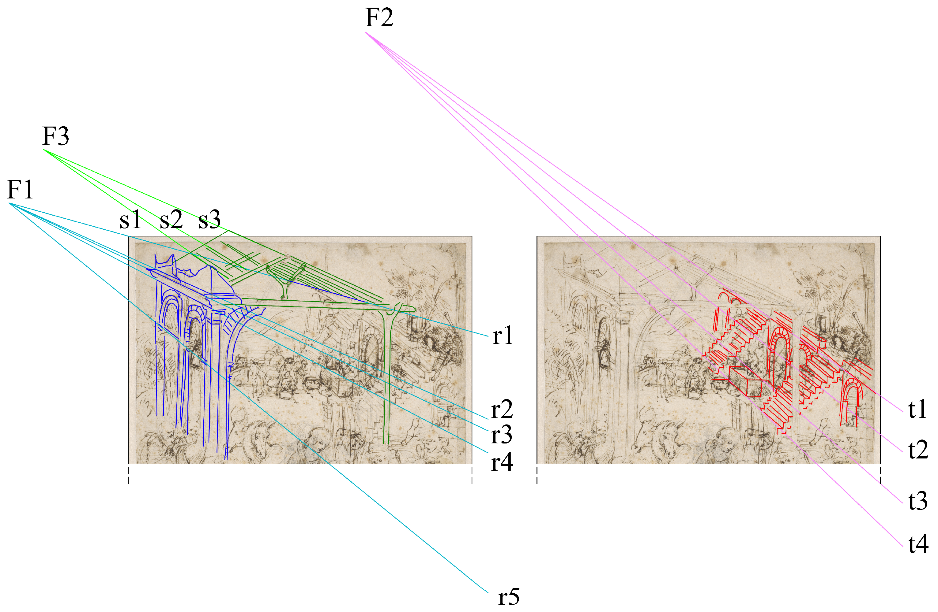
At a first glance, part of the scene (the hut of the Nativity) appears to be very close to an axonometric view. The illusion of axonometric construction comes from the fact that the straight line s3 (the ridgeline of the roof), is almost exactly parallel to the line r3 (the eave line) (see
Figure 4).
This conclusion, however, does not consider the nature of the drawing: a simple sketch without a rigorous perspective construction (there are no visible traces of construction lines or marked reference points). The drawing is quickly traced to clarify how to organize the future painting; in fact, the ridgeline is very short and very close to the paper boundary, thus, it might just have been drawn roughly. Furthermore, looking at other lines parallel to r3 and s3, e.g., the lines representing the rafters on the left side of the roof, these are roughly parallel to each other but are not exactly parallel to r3 and s3.
A more attentive observation shows that we are in presence of a different type of representation. Despite the occlusion of the low part of the complex in the center of the drawing (with the hut and the antique architectural ruins) by the figures in the foreground, not allowing an exhaustive reconstruction of the representation technique, the upper part of the central construction shows enough elements to express a reliable hypothesis about the viewing technique used. If we consider r1 (the eave line on the right), we can see that it is incident to r3 (the left eave line), at point F1. Furthermore, other lines (more or less explicitly traced) with the same objective direction of r1, converge to the vanishing point F1, e.g., r4 (the lower part of the cornice) and r5 (the springer line at the base of the arcs on the left). This proves that we are, in fact, not dealing with an axonometric view, but rather with a roughly drawn bird’s-eye perspective, where objectively parallel lines are not parallel with each other in the representation, as in axonometric views; they converge to very far vanishing points instead.
This type of representation is common in Leonardo’s work. As other authors have observed (e.g., [
25]), it is probably best described by Leonardo himself in Manuscript E, where he refers to it as “
prospettiva semplice” (i.e., “simple perspective”), described as follows: “
non vol vedere pariete in iscorto ma più in propria forma che sia possibile” [
26] (foll. 16r, 16v.) ((i.e., “one does not want to view any foreshortened wall but rather as nearly in their real form as possible”). Even if he does not explicitly use axonometric construction, he exploits the ability of the axonometric technique to give information about the mass layout by preserving the measurability of lengths and heights in the front of the building that is drawn parallel to the picture plane. This technique allows the use of a single view to overtake the limits of the method based on
ichnographia and
orthographia, as coded by Vitruvio [
21] (p. 27) and confirmed by Leon Battista Alberti [
27] (p. 28), of the need for two views. As is well summarized by Xavier: “Leonardo lived in the world of perspective, which he proclaimed several times as the unique instrument that makes it possible to get knowledge of nature and all the environment” [
28].
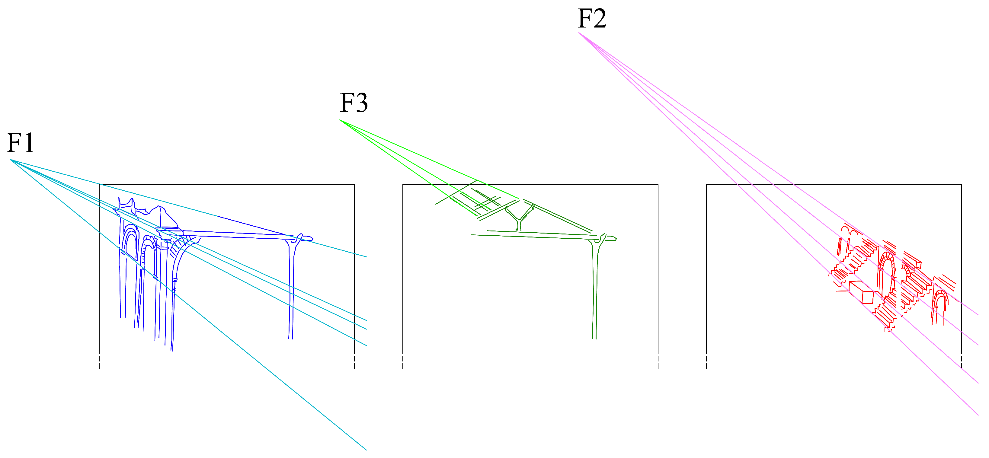
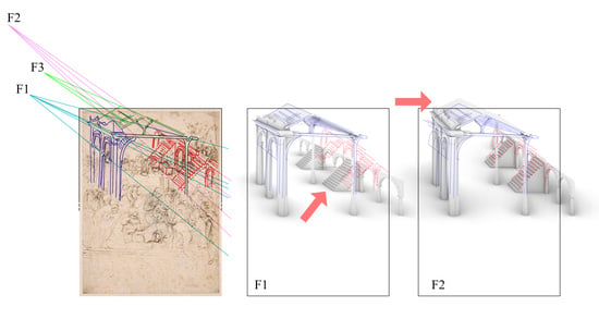
Other observations are possible, considering the antique architectural ruins, the altar on the right of the drawing, and the construction of their perspective. At first, we can observe that F1 is not only a vanishing point, but it is also the center of vision for the perspective of the ancient structure with arches to the left of the sheet. Given that effect, all the lines perpendicular to the picture plane should be converging to F1. However, if we examine the structure with stairs, we can see that the lines perpendicular to the picture plane (e.g., t1, t2, t3, t4) converge at a different point that we call F2, which is offset to an upper-left position compared to F1. Equally interestingly, if we analyze the wooden hut, we can see that the lines perpendicular to the picture plane that constitute it (e.g., s1, s2, s3) converge at a third vanishing point/center of vision (F3).
Finally, we can observe that F1, F2 and F3 are not aligned on the same horizon line (
Figure 5), an occurrence that implies different heights for the points of view.
We must point out that the three centers of vision identified (F1, F2 and F3) are rough estimations but we can certainly assume that, given the noticeable distance among them, they are three distinct points that would never converge at the same point, even considering the maximum possible error.
3.2. Observations on the Results of the Analysis
Nowadays, we know that vanishing points represent points on the picture plane where the projections of lines that are parallel in 3D space converge. So, when there are multiple vanishing points in the same perspective projection, it means that, in the 3D space, there are several sets of lines parallel to each other but that are not parallel to lines belonging to other sets. Nevertheless, lines that are parallel to each other, which lie on planes parallel to the ground, should always converge to vanishing points that belong to the horizon line. In Leonardo’s drawing, we have multiple vanishing points for lines that are all horizontal and perpendicular to the picture plane, as is easy to understand by observing the features of the architecture represented (buildings resting on horizontal ground and with straight vertical walls). Thus, if we consider the structures as three straight standard structures, they simply cannot belong to the same 2D projection space.
At this point, the reconstruction of a single global 3D scene (when considering the straight structures constraint above, and when observed from a single point of view) that entirely overlaps with Leonardo’s drawing seems to be an impossible task. The only solution that we can achieve is a 3D scene that, when observed from one of three preset viewpoints, delivers a 2D projection where only one architectural element at a time overlaps with Leonardo’s strokes, while the others do not. We will explore this possibility in
Section 4.1.
There is another possible approach that would make all structures coexist in the same 3D scene while making their 2D projection globally overlap with Leonardo’s drawing, even if seen from one single viewpoint. As we said, the vanishing points must lie on the same horizon line only when the sets of parallel lines belong to horizontal planes; so, if we give up the constraint that the three structures must lie on a planar horizontal ground and that their walls must be at a 90° angle, an infinite number of valid out-of-square building variations is suddenly possible. We will show some of these variations in
Section 4.2. Even if this is only a formal exercise, one surely not considered by Leonardo, the outcome of this experiment is still interesting as a way to measure the “error” made by Leonardo, and it might open interesting debate on the possible reasons for this conscious or unconscious choice by the artist.
In summary, we observed that the three architectural elements represented (from left to right: the structure with arches, the Nativity hut, and the structure with stairs) are depicted using the “prospettiva semplice”. Although the centers of vision and the horizon lines of each of the three architectural elements are outside the bounds of the paper, and no strokes show a rigorous construction, it is clear that they are independently drawn and each one was depicted as if it were observed from a different point of view. From these observations, it can be inferred that the three structures belonged to different and autonomous representations, and maybe even come from different previous drawings represented on a different sheet.
4. Generation of the 3D Models
Generating a 3D model when starting from a single image is a well-known problem that has been widely studied, especially over the last few decades, starting with the seminal work by Antonio Criminisi [
29]. The excellent results achieved using photogrammetric techniques (e.g., [
30]) were further improved by exploiting AI (Artificial Intelligence) technologies for automatic 3D reconstruction [
31]. However, in our case, since we are starting from a drawing roughly sketched and not from a picture captured with a photo camera (the equipment usually considered in these studies), it is more efficient to adopt methodologies based on graphical human-driven constructions. This type of approach also guarantees a more robust control of the constraints needed for a suitable interpretation of shapes.
Nowadays, it is common knowledge that restoring the third dimension from a 2D perspective projection is only possible if we have additional information because the central projection does not allow the full restitution of the true form of the objects, if the distance of the point of view and its position in 3D space, and the scale of the objects on the picture plane, are unknown. Such information might be in the form of lengths or angles. If there are no available parallel projections (e.g., the plan or a section) or a second perspective view of the same subject that would constrain the scene to certain exact measurements, we can only constrain the scene by extrapolating some features from the single perspective projection available. For instance, we can search for construction lines at 45°, which would allow us to recognize squares and then achieve depth calculations using the measurement of the side of the square on the picture plane, as was possible in the case of the
Study for the Background of the Adoration of the Magi [
9]. Unfortunately, in the study for the
Adoration of the Magi held at the Louvre Museum, no preliminary constructed vanishing lines nor any square grid on the ground plane are visible. At this point, the only path to follow is setting out assumptions based on experience and on the rules of the perspective construction that were known in Leonardo’s time in the workshops of painters in Florence [
13].
For the two structures, referring to F1 and F2, finding possible features that constrain the dimensions of the scene was relatively straightforward. As a plausible assumption, we assumed, for both the left wall of the classical structure with the Nativity hut and for the structure with stairs (other than that they lie on a flat horizontal plane and they have straight/orthogonal vertical walls, as stated previously), that the arcs of the two structures are all semi-circular. This simple hypothesis is sufficient to reduce the degrees of freedom to one, making it possible to measure all the elements of the structures as if they belong to two independent scenes.
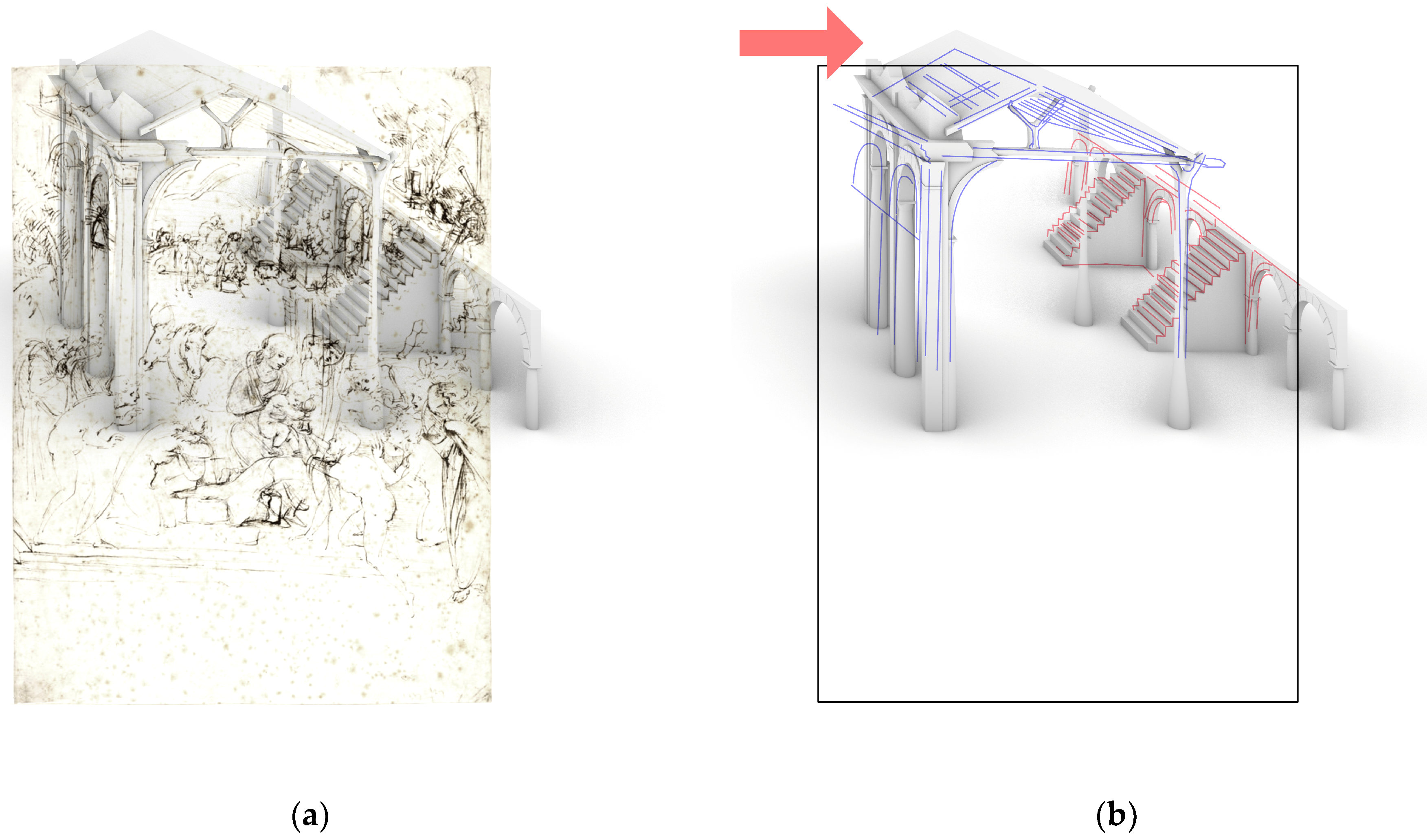
However, regarding the roof pitches that refer to F3, we do not have any feature that we can use to achieve the same result. Furthermore, the eaves lines are pointing to F1, while the ridgeline is pointing to F3. Because of that, it would be impossible to find the exact location of the point of view referring to F3 in 3D space (this would be called PV3) and thereby generate a 3D model where the architectural elements are as would be seen in the real construction (e.g., a roof with flat pitches and horizontal eaves lines). To solve this problem, we used a construction coherence criterion. We decided not to consider the roof pitches as independent structures but, instead, as deformed elements that align with the strokes drawn by Leonardo when seen from PV1 (the point of view in space projected on the picture plane, along the central axis of vision that passes through F1). So, from now on, we will no longer consider F3.
These considerations led to the reading of the scene as being composed of two independent structures (the complex hut–classical architecture and the classical architecture with stairs) observed from two different viewpoints in Leonardo’s drawing. These two objects were generated as two independent 3D models, using the features associated with the perspective to which each relates (
Section 4.1).
The last step of our work is to make them coexist in the same projected space. To achieve this, we will deform one of the two 3D generated structures to make it match the strokes by Leonardo from the other point of view. In this way, at least one of the structures will be out of square (
Section 4.2).
4.1. Construction of the 3D Models, Considering Structures with Rectangular Plans, Straight Vertical Walls and Two Points of View
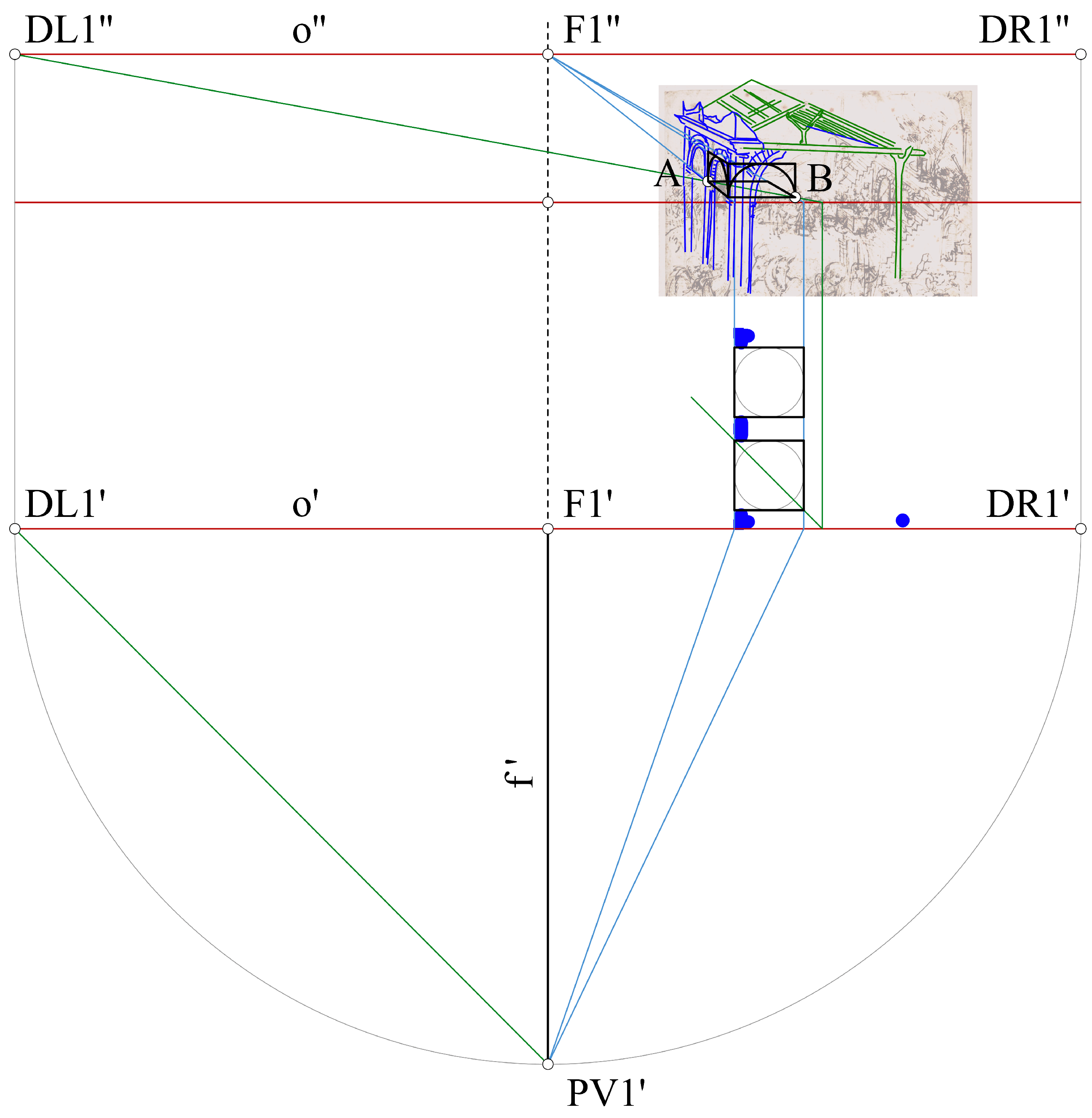
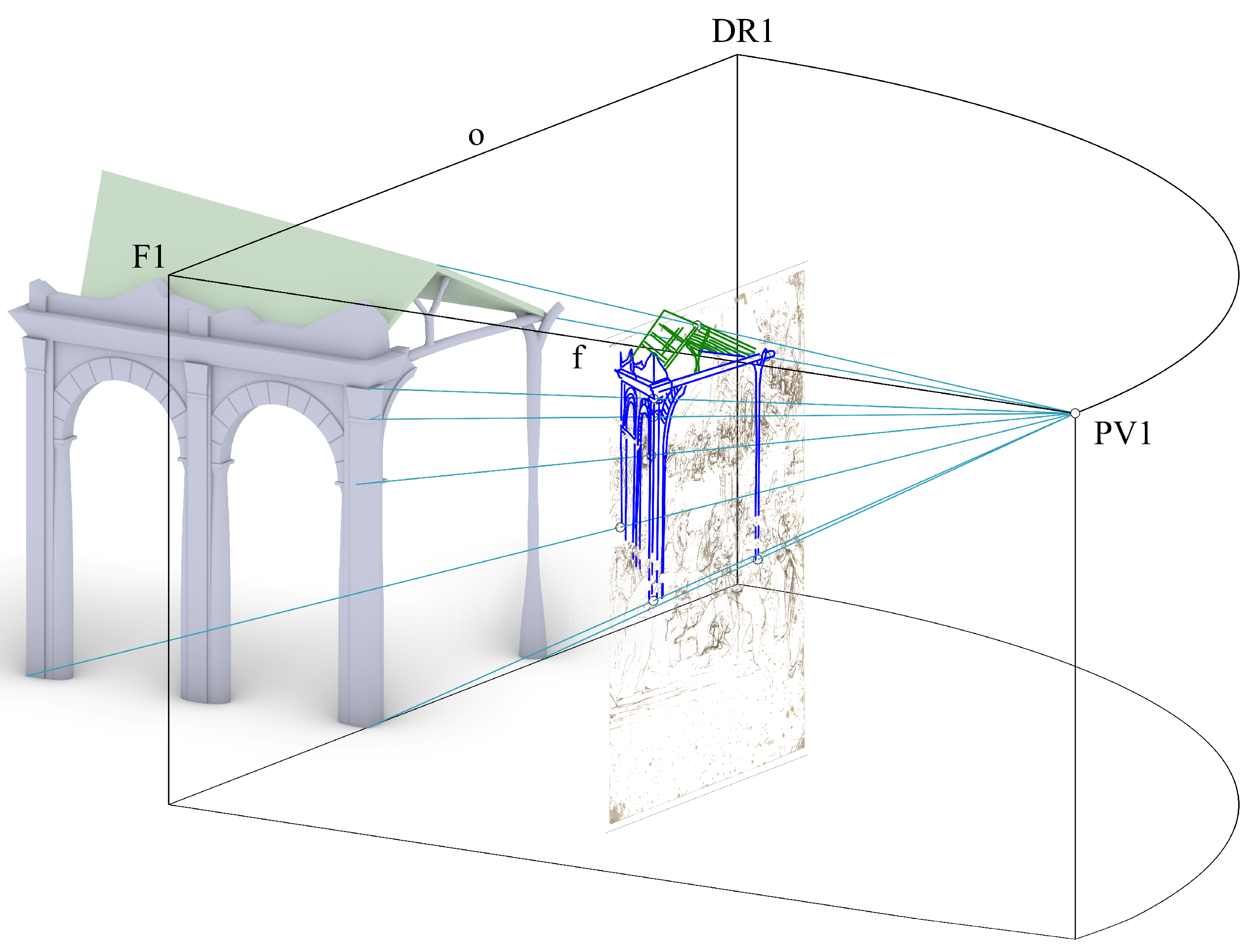
The first step consists of finding the exact 3D position of the point of view associated with F1 that we will call PV1 (refer to
Figure 6), which could be somewhere on the central axis of vision (i.e., the line of sight, f) perpendicular to the picture plane.
As we have said, to find a univocal distance from the picture plane to PV1, we need an additional constraint that is not directly deducible from the picture, so we assume that the two arcs on the left of the ancient building in ruins are semi-circular.
Starting from this perspective view, we measure the radius of the circumference starting from the point of the arc closer to the picture plane, exploiting the lines perpendicular to it that delimit the upper point and the two lower points of the semi-circumference generating the skewed arc. A 90° rotation of the height of the semi-circumference (measured vertically) allows us to identify the center of a new semi-circumference that is homologous to the first one but belongs to a plane parallel to the picture plane. This new semi-circumference is drawn in its true shape. Then, we draw the half-square circumscribing the two arcs: the one in the perspective view by Leonardo and that on the picture plane that is traced now.
Next, we draw a line through points A and B. This line in 3D space is a 45° line with regard to the picture plane; thus, if we extend it upward to the horizon line (o) we find the so-called distance point (DL1). Once DL1 is found, it is possible to locate the position of the point of view (PV1) in the 3D space, and we can reconstruct the 3D model of the complex classical architecture/Nativity hut as shown in
Figure 7.
To complete the 3D model, the part of the structure nearest to the ground plane (mostly occluded by other figures in the foreground in Leonardo’s drawing) was reconstructed congruently with the upper part, exploiting the small number of vertical lines that are not occluded to determine the height. An additional abutment was added at the back-right corner of the hut structure, to provide more solid support to the roof. It was modeled as the support drawn by Leonardo in the front of the hut.
The roof pitches, differently from the rest of the structure, were modeled as perspectival objects because most of the lines by Leonardo that define them are directed toward the vanishing point F3. This solution allows an accurate alignment between the model of the roof pitches and the strokes by Leonardo when the scene is observed from PV1. The 3D model of the structure with stairs, as shown in
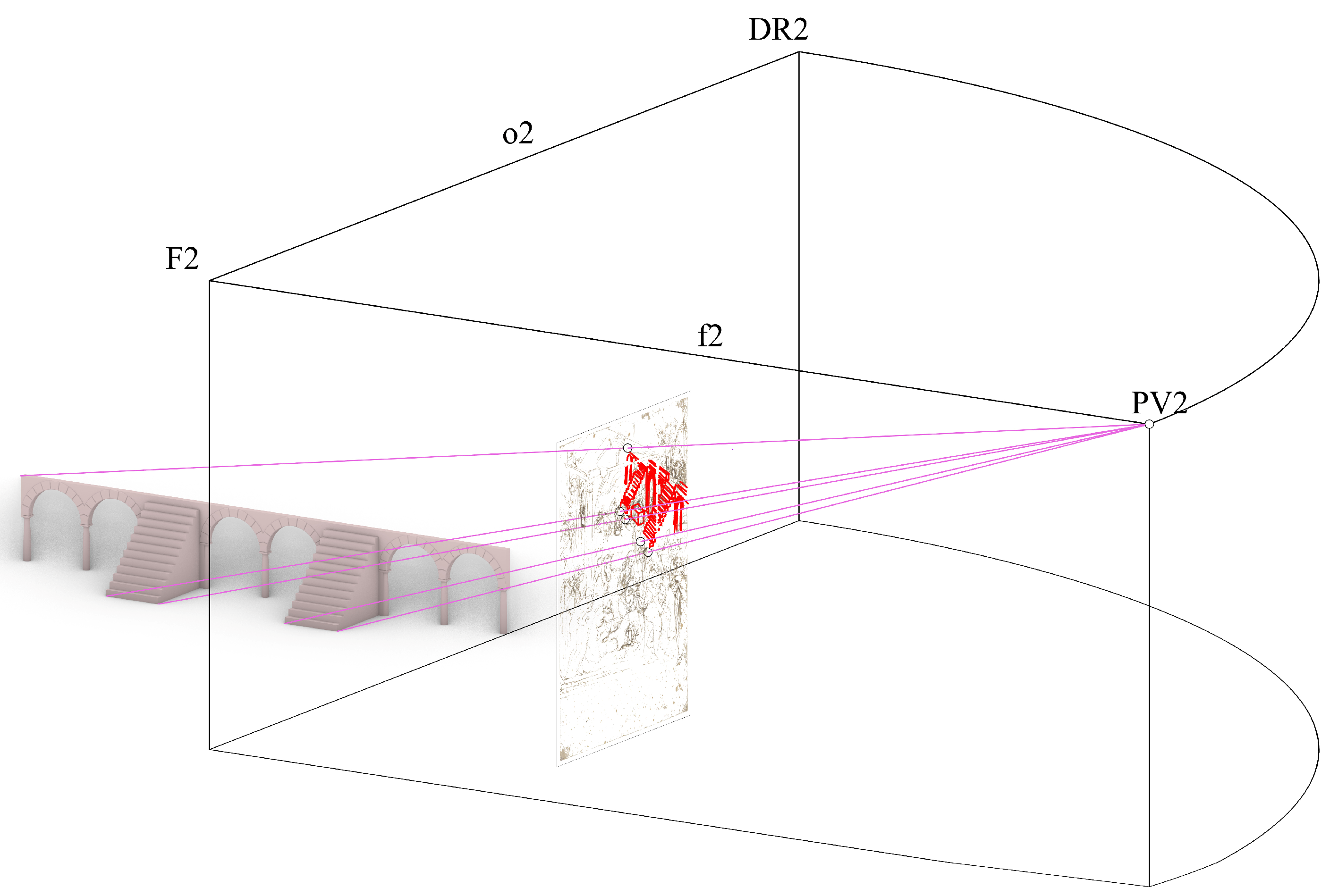
Figure 8, was reconstructed using this same approach, exploiting again the hypothesis of semi-circular arches.
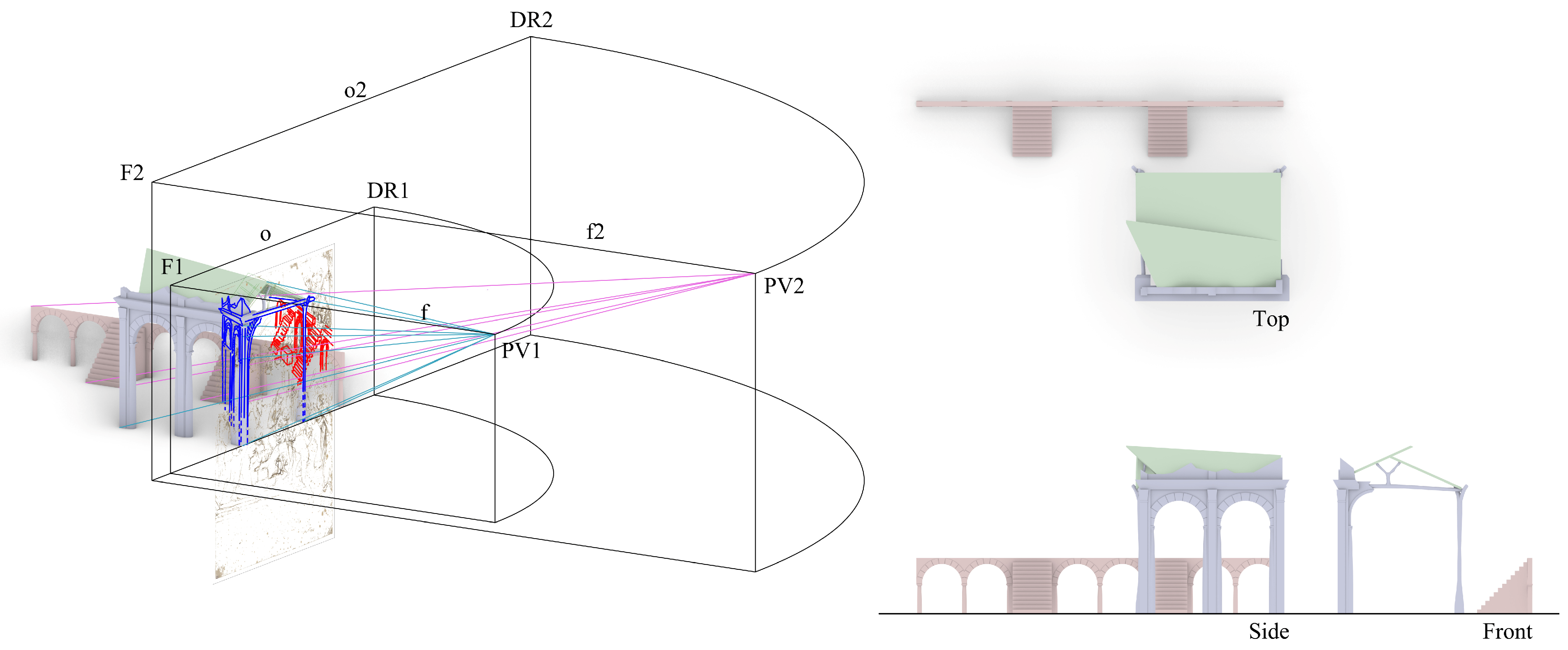
After we built the two models independently, we placed them in the same scene by assuming a common ground plane; their front façades are parallel to the picture plane and match Leonardo’s tracing on the picture plane (
Figure 9). For the structure with stairs, a further hypothesis was needed. The arc closer to the picture plane, which Leonardo draws, is partially occluded by the ruin in the foreground; thus, we had to assume that the arc was the last one of a series (we assumed that because of symmetry with the other end of the structure). By setting this further assumption, we were able to place the two structures in the same 3D space. This supposition allows us to view the scene from PV1 and PV2, while at the same time visualizing the other misaligned model.
The two views in
Figure 10 show the alignment between the model of the classical architecture/Nativity hut and its projection drawn by Leonardo when viewed from PV1, while the model of the structure with stairs is misaligned; and the opposite when the scene is viewed from PV2 (
Figure 11). Another interesting observation is that in the resultant 3D model the widths of the stairs are almost equal, as well as the widths of the arches. This feature is surprising, because such a precise dimensioning of a structure using a freehand perspective, without reference lines or any grid on the ground floor, hardly matches with the expected metric inaccuracy of a sketch drawing.
4.2. Construction of Out-of-Square 3D Models Considering Two Points of View
We now have: the 3D model of the complex with the Nativity hut compatible with F1, and the 3D model of the classical architecture with the stairs compatible with F2. The next question is on how to achieve a view of the 3D model of the complex with the Nativity hut that is compatible with F2 and a view of the 3D model of the classical architecture with the staircases that is compatible with F1. The only way to do this is by dismissing the constraints that we imposed on the structures in the previous section (
Section 4.1). However, by removing these constraints, an infinite variety of solutions is suddenly possible. Thus, we need to add new constraints to reduce the degrees of freedom to one again.
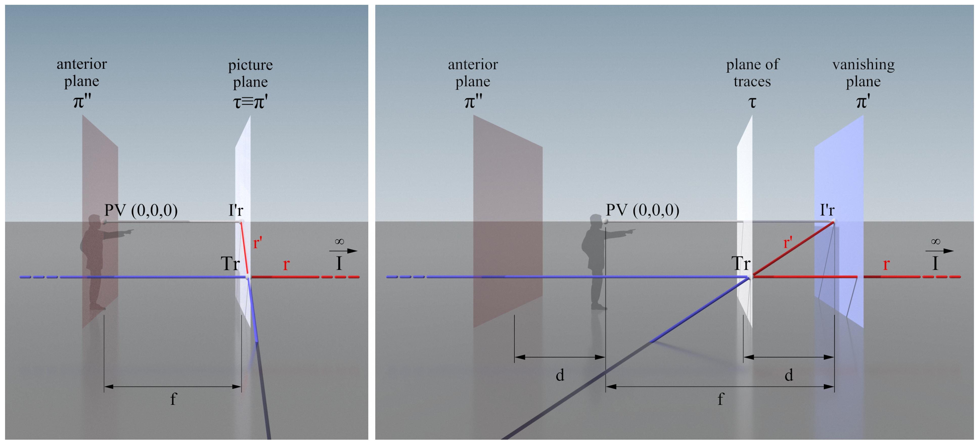
To address this problem, we used the rules of solid perspective (
Figure 12). The solid perspective machine described in [
32,
33,
34] allows the deforming of a solid object in 3D space, while keeping its projection on the picture plane unvaried (the picture plane becomes the collineation plane in solid perspective). The family of 3D models generated through a solid perspective machine is related through a solid homology.
The solid perspective machine is described by the following simple formulas [
34]:
and the notation of the formulas is visualized in
Figure 12, where:
f is the focal distance, namely, the distance between the point of view (PV) and the vanishing plane;
d is the distance between the plane of traces and the vanishing plane, as well as the distance between PV and the anterior plane;
The vanishing plane (sometimes called the first limit plane) is the plane of the vanishing points and vanishing lines;
The plane of traces (sometimes called the collineation plane) is the point where the lines belonging to the real space, and their perspective projections belonging to the scenographic space, intersect;
d determines the compression (anisotropy) of the scenographic space;
When d is equal to 0, the scenographic space is squashed into a plane that forms the plane of traces and the vanishing plane, converged into the picture plane while, at the same time, the anterior plane passes through PV;
Any point belonging to the anterior plane is projected to infinity from the real space to the scenographic space.
The scenographic space is the anisotropic space where the perspective model (in our case, the skewed model) belongs;
The real space is where the objective model belongs;
x’, y’, z’ are the coordinates of a point in the scenographic space (any point of the skewed model in our case) and refers to a system centered in a PV, with its Y-axis perpendicular to the defined planes;
x, y, z are the coordinates of the same point in the real space (any point of the undistorted model, in our case).
By applying these formulas to each point of the 3D undistorted model, generated as described in
Section 4.1, we can deform it in 3D space while keeping its projection on the plane of traces unvaried, if seen from the same point of view.
However, our goal is to generate a 3D model of the complex with the Nativity hut that overlaps with Leonardo’s strokes, when viewed from PV2, and the 3D model of the classical architecture with the staircases from PV1.
When changing the point of view, the projection of the object on the plane of traces would change accordingly. Thus, the solution we adopted was to squash the 3D model onto the plane of traces (which becomes the picture plane when d is zero) by reducing the distance d to zero, then returning the model to its solid state by increasing d again but after the position of the point of view was changed from PV2 to PV1 at the inversion point.
To invert the direction of the solid transformation we can invert the previous formulas as follows [
34]:
However, by squashing the 3D model completely into a planar space, we would lose track of which points of the model were closer to or farther from the viewer. This would prevent the transformation from working properly with these formulas alone. We could use expediency to make it work anyway by preserving a small displacement on the vertices of the squashed model, which is achievable by assigning to d a value that is close to zero but is not exactly zero. In this way, the “almost-squashed” model would preserve the information about its original topology and spatial conformation, allowing these formulas to work.
At this point, we focus on the structure with arcades and perpendicular staircases.
Figure 13 shows the first out-of-square variation that we propose (green model). This variation is obtained by deforming the original straight model (pink model) generated by inverse perspective projection from PV2 so that it overlaps with the drawing by Leonardo when viewed from PV1 instead. In this way, from the same point of view (PV1), we can see both the structures with the hut and the stairs overlapping the original drawing. This deformation of the 3D model complies with the rules of the solid perspective machine.
By testing this methodology using a common 3D modeling software (we selected Rhinoceros [
35], a commercial 3D modeler that is very popular in the architectural field), we observed that, depending on the tolerance of the software and the chosen size of
d, the result might introduce non-trivial errors. Thus, we chose to adopt a process based on the same rules but that performed the task graphically instead.
To summarize, the process consists of constructing the bounding box of the 3D model, further subdividing it into smaller volumes (in this case, they corresponded to specific architectural elements, one for each arc and stair of the structure). Then, we projected the vertices of these bounding box modules on the picture plane by sliding the points on the view rays converging on PV1 and re-projected them in 3D space by moving the points along new view rays that converge on PV2. After that, we used the CageEdit tool of Rhinoceros to deform and align the content of each module, from the straight bounding box to the skewed one. The CageEdit tool is a global shape modifier allowing us to deform objects smoothly using two- and three-dimensional cage objects [
36]. With cages of only two points on each axis, the straight lines of the 3D model driven by the cage are reoriented but preserved as straight lines. The CageEdit formulation does not strictly comply with the rules of solid perspective, but the error can be mitigated by adopting smaller bounding-box modules. Nevertheless, we observed that the error achieved with this method was negligible according to the accuracy of the drawing, and the process was much faster compared with the rigorous application of the formulas for each point.
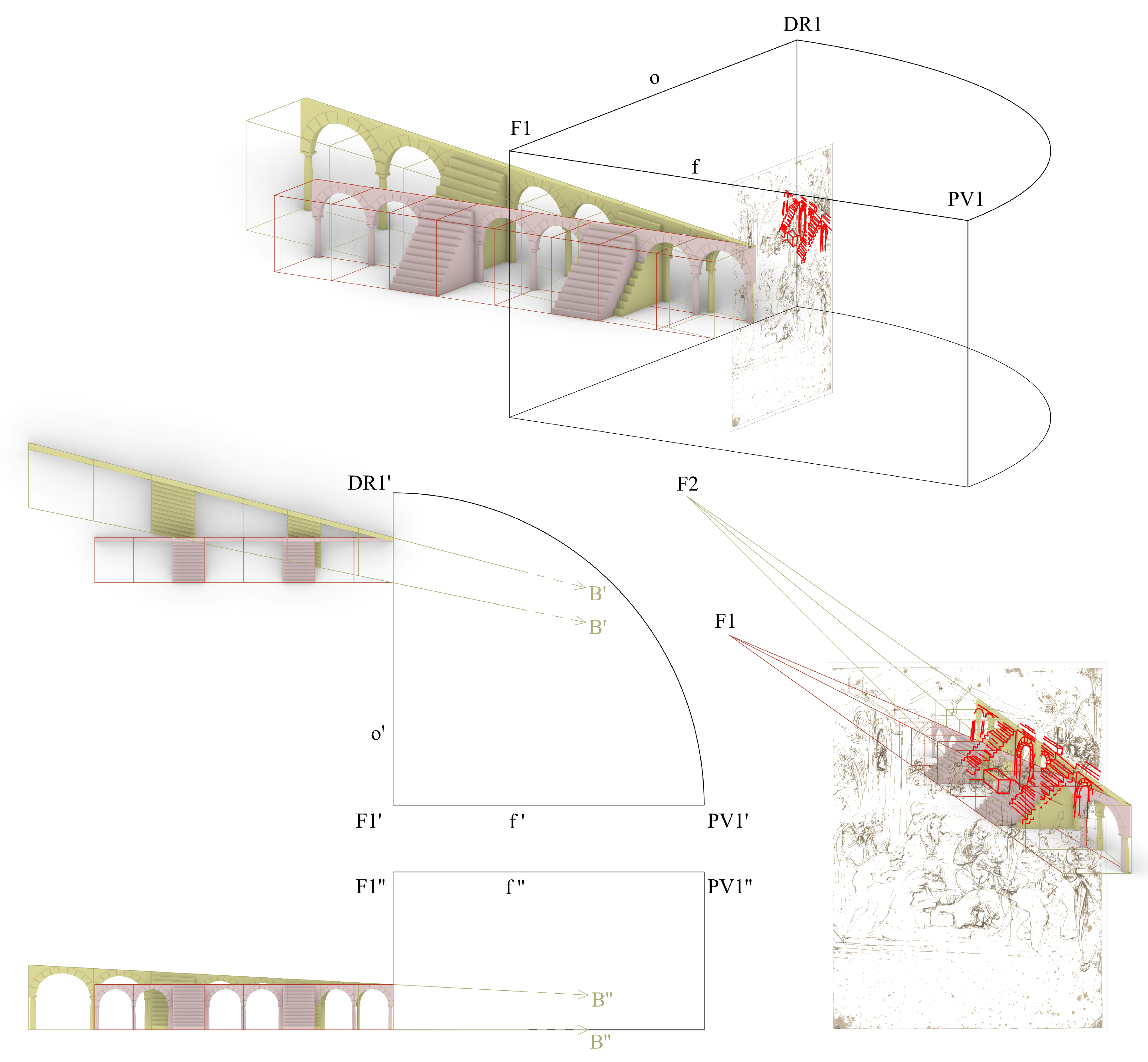
Without additional constraints, an infinite number of valid solid variations that perfectly align with Leonardo’s drawing would have been possible. Thus, for the solution shown in
Figure 13, we assumed that the external wall on the right is perpendicular to the picture plane. However, by setting this constraint, the deformed model will not lie on a horizontal plane. The structure is, in fact, not connected to the ground plane: the only point of the structure that touches the ground plane is in correspondence with the picture plane. Another interesting observation is that the long edges of the bounding box that were perpendicular to the picture plane in the non-deformed 3D model are now converging to a very far point that we call A in 3D space and, at the same time, their projections on the picture plane now match the vanishing lines that meet at F2; this is consistent with the expected outcomes of solid perspective.
A second possible solution is shown in
Figure 14. This variation of the 3D model is the only possible solution that aligns the 3D model with Leonardo’s drawn strokes (if viewed from PV1) while resting on a flat horizontal plane. Additionally, in this case, the major edges of the bounding box that were previously parallel to each other and perpendicular to the picture plane are now converging to a very far point
B in 3D space; at the same time, their 2D projections are converging to F2.
The same construction could be performed for F2 (i.e., deforming the complex classical structure/Nativity hut, while keeping the structure with stairs as having a rectangular base and straight vertical walls) but, for the scope of this paper, it is not necessary to also show this variation.
5. Results and Conclusions
From the analysis of the study drawing for “The Adoration of the Magi” by Leonardo da Vinci, we discovered that the drawing—analyzed as a global composition—does not follow the rules of the construction of perspective. In fact, three distinct, independent centers of vision can be inferred through examination of the strokes drawn by the artist, one for the classical architecture on the left of the sheet (F1), one for the structure with the stairs (F2), and one for the roof pitches of the Nativity hut at the center of the drawing (F3). This means that if we consider the architectural 3D structures in their objective space structures, they cannot belong to the same 3D space. These discrepancies are unusual for an expert draftsman such as Leonardo. His trained eye and hand in this drawing are well proved locally in the dimensioning of the structures, which are surprisingly precise. The degradation of distances of the steps and the spans of the arcs, along their relative vanishing lines, are almost perfectly dimensioned. If the use of the lead point (at first) and the pen and ink (later) to confirm the decisions made implies a great deal of reflection, this is an amazing feature for a quick study drawing in the form of a freehand sketch.
To explain the errors in the whole construction of perspective, which contrast with the very high level of local accuracy, a simple hypothesis could be that he changed his mind halfway through. Had he used the same center of vision for all the structures, he would have been forced to occupy the center of the scene with the stairs (using F1 only), or inversely, the complex classical architecture/Nativity hut building would have been too skewed, making the left façade very hard to draw and distinguish, also making the top part of the roof exceed the paper’s boundaries (using F2 only). Therefore, rather than a mere error, a more plausible hypothesis is that Leonardo treated this drawing as a fast study sketch where each element was independently considered and constructed, to meditate on the composition balance without putting too much effort and time into rigorous constructions that were not the most important aspects at that stage of the work.
A second hypothesis to explain the use of different independent centers of vision is that he might even have traced them from other drawings he had previously made or those drawn by other artists, simply adding elements as in a collage, where the interest is not in the specific element but the whole arrangement. Drafts of this type do not require any formal accuracy; however, since they are designed to study the proportions and verify the balance of the scene, they require careful placement of the subjects in play, such as characters, objects, and scenographic structures, all elements integral to the graphic analysis of the drawing.
Moreover, this hypothesis would better explain the high accuracy of the degradation of the distances along the vanishing lines on each individual element.
Finally, these results are compatible with previous studies of Leonardo’s drawing [
8,
15] that are based more on traditional art history studies rather than graphic analysis, as in our case.


