1. Introduction
Local mechanisms are generally characterized by macro-blocks, separated by a number of cracks, where relative motions are activated during an earthquake [
1,
2]. For these mechanisms, there is a wealth of literature references aimed at calculating the ultimate load factors by means of limit analysis, especially with kinematic approaches considering frictional behaviour [
3,
4,
5,
6,
7,
8,
9,
10,
11,
12]. In the last few decades, researchers have also developed analytical methods in the field of finite element (FE) analyses to examine ordinary masonry constructions [
13,
14,
15,
16,
17] or have implemented large scale and detailed numerical investigations to study monumental constructions like churches [
18,
19,
20,
21,
22,
23,
24,
25,
26,
27,
28,
29,
30,
31,
32,
33].
The evaluation of potential local mechanisms is one of the most commonly used approaches to study the vulnerability of masonry buildings. According to the European [
34] and Italian Codes [
35,
36,
37], the global and local mechanisms can be studied by using different investigation types, namely linear static, non-linear static, linear kinematic and non-linear kinematic analyses. With regard to linear static analyses, the reference seismic action at ultimate limit state (ULS) is reduced through a behaviour factor to allow for a check in the elastic field. This implicitly takes into account the further displacement capacities once the limit resistance is reached before the structure attains the ULS. It is emphasized that the application of this method in the case of historic buildings can be problematic due to the difficulty of defining an appropriate behaviour factor.
With reference to non-linear static analyses, they consist of the evaluation of the structure seismic behaviour at ULS through the representation of a proper force–displacement curve. In particular, the capacity displacement at ULS is compared with that required by the earthquake (demand displacement), evaluated in spectral terms. Such an analysis can be performed with a model that represents the overall structure behaviour or through models of substructures (macro-elements). The analysis consists of applying both gravitational loads and a system of horizontal forces proportional to either structural masses or the vibration first mode. In the case of masonry churches, the variety of geometries and constructive systems makes it impossible to define an accurate distribution of static forces equivalent to the earthquake. Instead, it is easier to use the limit analysis for the collapse kinematics, assigning to each possible kinematic mechanism an increasing displacement configuration. This method is called non-linear kinematic analysis and allows one to evaluate the construction displacement capacity after the mechanism activation. Nevertheless, this method is not easily implemented for large scale or parametric analyses due to large computational efforts. Contrary, where seismic analysis is based on the separate evaluation of different local mechanisms, both for global and local analysis it is easier to use linear kinematic analysis based on the kinematic theorem which, as defined in [
37], consists of calculating the horizontal load multiplier activating each possible kinematic. This method is preferred for the result reliability and for its simplicity of use due to a well-established behaviour factor, assumed equal to two for masonry churches. The aim of this paper is therefore focused on the linear kinematic approaches applied to masonry churches. Linear kinematic analysis is based on the determination of the system resistance with regard to the horizontal acceleration activating the local mechanism. This approach is in terms of force and a behaviour factor is introduced to decrease the demand depending on the ductility features estimated for the masonry structure [
35]. This analysis consists of quantifying the seismic collapse factor
α, which is the horizontal load multiplier activating the local mechanism of a given macro-element. In fact, it is possible to consider the masonry structures as composed of different macro-elements involved by kinematic mechanisms. In particular, a macro-element is a constructive and recognizable part of the structure, which has a fully describable behaviour under seismic actions. The collapse multiplier α is obtained by applying the principle of virtual works, equalizing the total work performed by external forces to that of the internal forces.
In this study, local collapse mechanisms based on the out-of-plane behaviour of masonry walls are evaluated in 12 masonry churches located in the Italian city of Teramo. The main local mechanisms considered are facade overturning, vertical bending, corner overturning and roof gable wall overturning. For each mechanism, parametric analyses are conducted with varying height and thickness as geometrical features of walls, with the final aim to find useful and simple theoretical relationships to calculate the related collapse multiplier.
2. The Case Studies
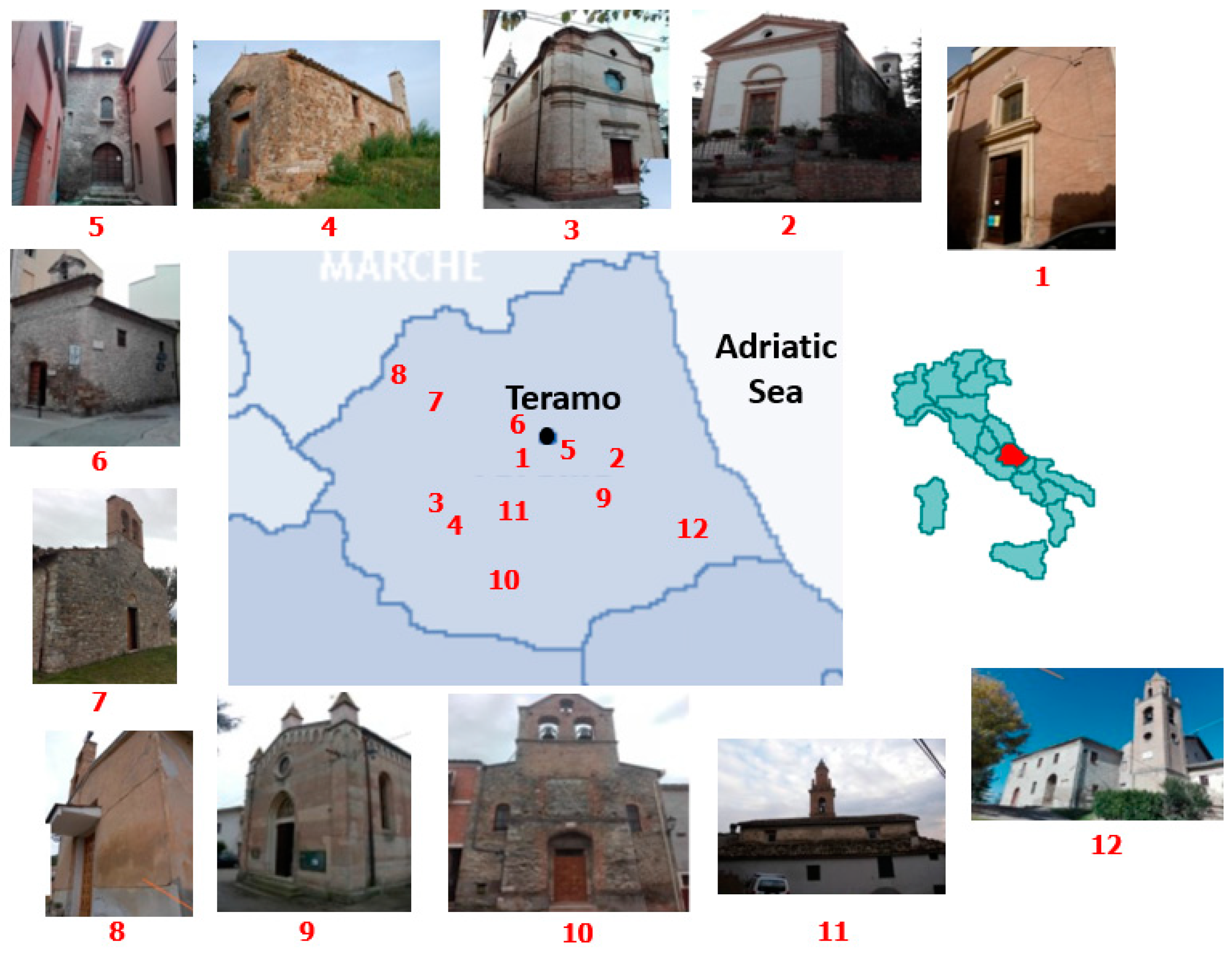
The case studies herein examined are represented by 12 churches located in Teramo and its districts (
Figure 1 and
Figure 2). These churches were chosen as case studies since they were investigated by some of the authors in order to evaluate their usability after the 2016 Central Italy earthquake. Moreover, they belong to the same territory and are placed a few kilometres away from each other, so are subjected to very similar spectral accelerations. They are similar constructions, generally characterised by one single-storey, small dimensions and architectural configuration, the latter mostly made of one nave (only in two cases are there more than one nave) and an apse. Five of the 10 churches are also provided with a bell tower. In general, the load bearing vertical structures of all churches are made of chaotic rough stones, which are covered in most cases by timber trussed and gable roofs. In a few cases, the presence of a cross vault roof and a barrel one is found. The investigated churches are:
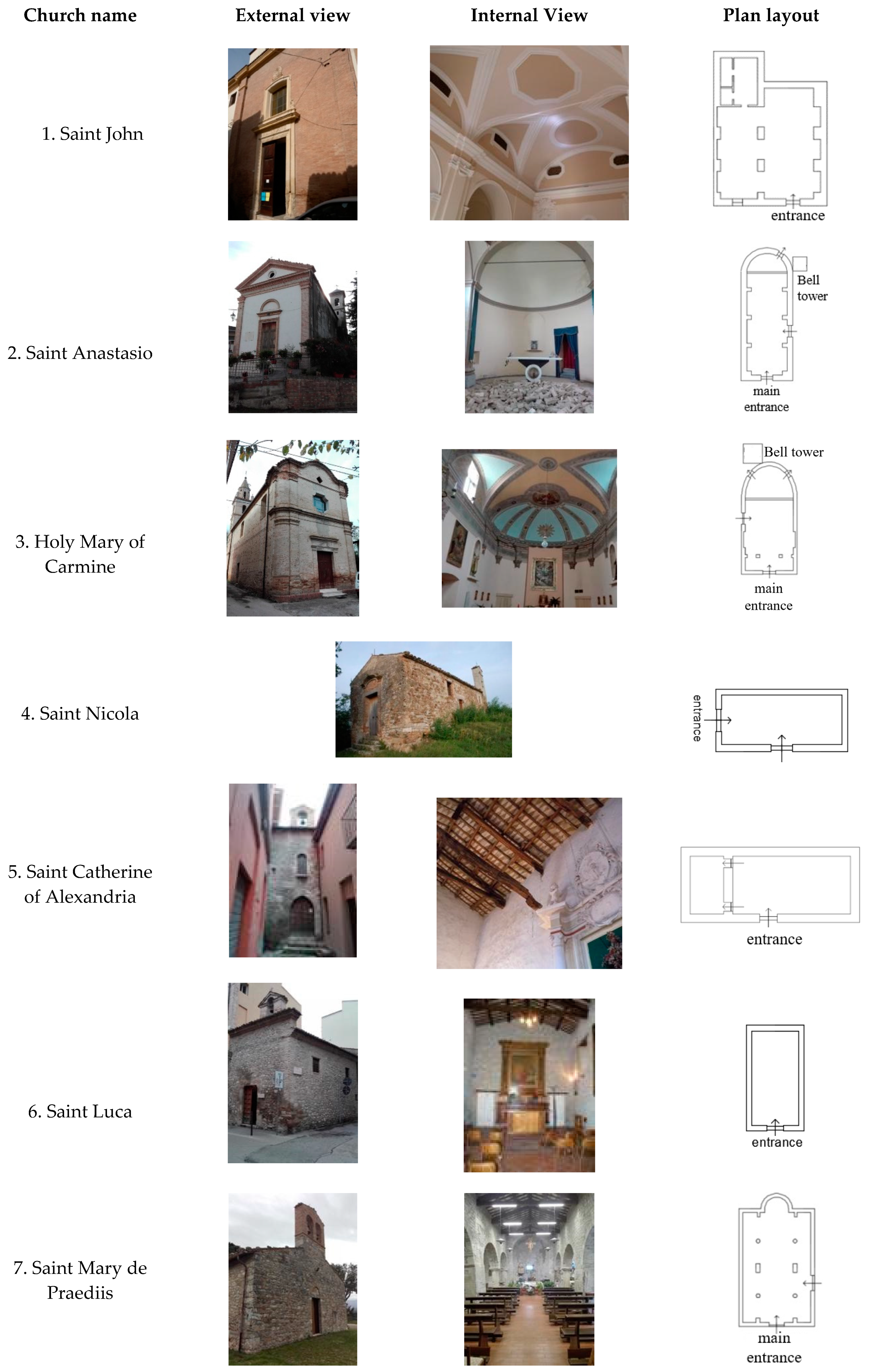
St. John, placed in the historic centre of Teramo and built in 1736.
St. Anastasio, located in Poggio Cono, a small district of Teramo. It was built in the 17th century and nowadays it is unusable because of damages provoked by the 2009 April 6th earthquake.
Holy Mary of Carmine, located in Cavuccio, a district of Teramo, built from 1832 to 1837.
St. Nicola, located in Cavuccio, a district of Teramo. It was built in the 16th century, presumably in 1551. Nowadays, the church is unusable.
St. Catherine of Alexandria, located in the historic centre of Teramo. The church is opened to the people only few days per year during the celebration of the Saint Catherine’s festivity. It was built around the 9th century and it is considered one of the oldest and the smallest church in Abruzzo.
St. Luca, located in Teramo and built in the 14th century. Currently, the building is not used for religious services, but it is rather used occasionally as a chapel and as a place for art exhibitions.
St. Mary De Preadiis, located in Castagneto, a district of Teramo. It was built between the 10th and the 11th century and it is considered to be one of the oldest churches in Teramo.
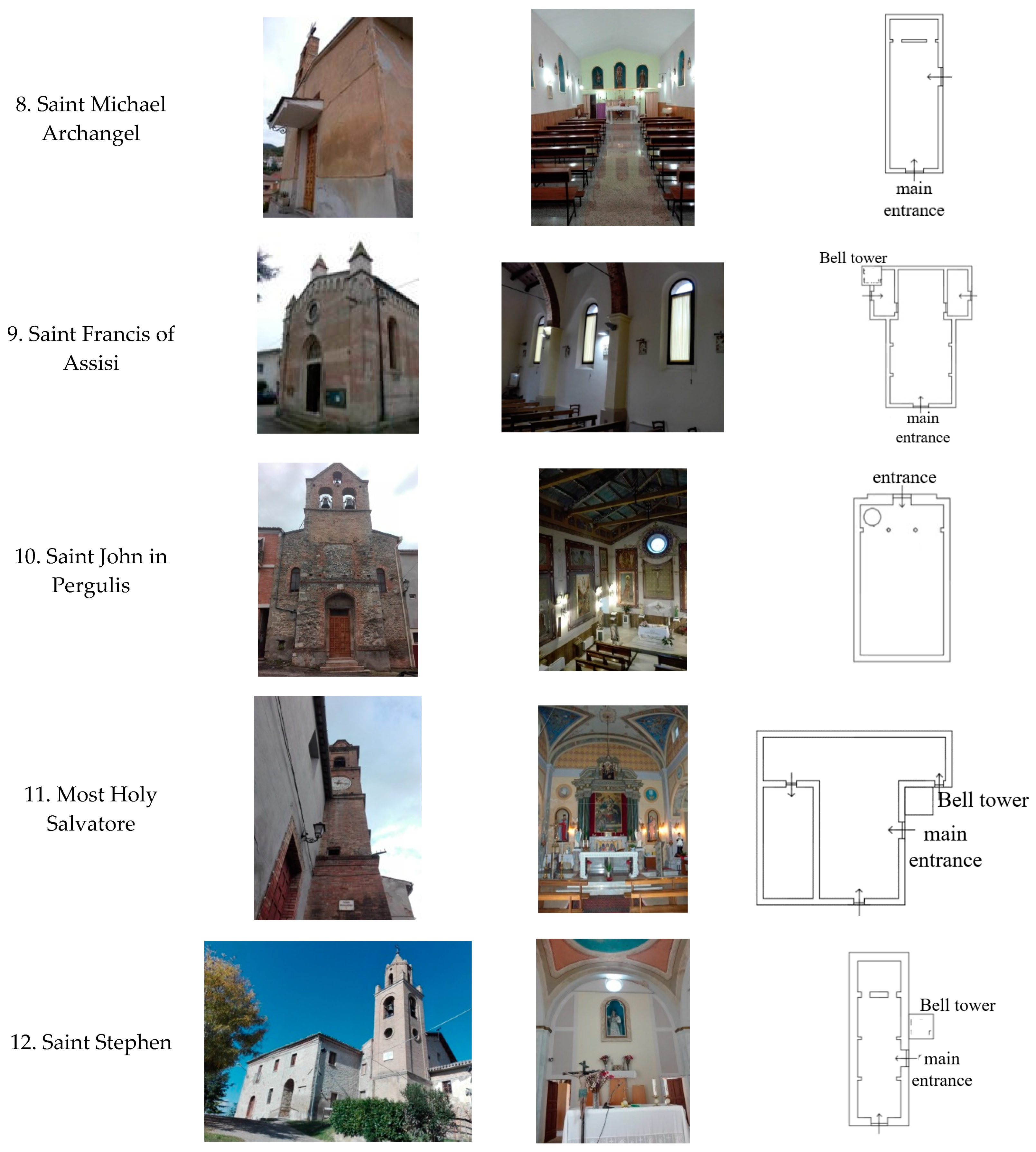
St. Michael Archangel, located in Magnanella, a district of Teramo, and built in the 19th century.
St. Francis of Assisi, placed in Villa Vomano, a district of Teramo. It was built in 1937.
St. John In Pergulis, located in Valle San Giovanni, a district of Teramo, which was probably built in the 16th century.
Most Holy Salvatore is in Frondarola, a district of Teramo. It was built around 1330, but the structure which we can see today was renovated in the 19th century and restored in the second half of the 20th century.
St. Stephan, located in Rapino, a district of Teramo. It was built around the 11th century and it was renovated in 1932.
Table 1 shows the main geometrical dimensions of each church. In addition, both the height and the thickness of façade walls of each church are reported in
Table 2, where the average and maximum values of height, together with the average and minimum values of thickness for facades of examined ecclesiastic constructions, are also provided.
3. Local Collapse Mechanisms
3.1. Description
Local collapse mechanisms analysed in the current study are facade overturning, vertical bending, corner overturning and roof gable wall overturning. For each mechanism, the collapse load multiplier α is evaluated. In order to estimate the horizontal load multiplier acting on macro-elements, the following parameters should be taken into account [
35]:
- −
Wi, weight of the i-th macro-element;
- −
FVi, thrust vertical component of arches or vaults in correspondence of the i-th floor;
- −
FHi, thrust horizontal component of arches or vaults in correspondence of the i-th floor;
- −
PSi, floor weight of the i-th level;
- −
PVij, i-th load transmitted overhead to the j-th macro-element;
- −
P, load transmitted by roof beam;
- −
N, generic vertical load acting on the macro-element top;
- −
PH, static thrust transmitted by the top floor;
- −
PHij, i-th static thrust component transmitted by the top floor on the j-th macro-element;
- −
Ti, action of metallic tie rods at the i-th floor;
- −
si, wall thickness;
- −
hi, vertical distance from the application point of the action transmitted by the floor and/or the metallic tie rod of i-th floor to the hinge of the i-th macro-element;
- −
hPi, vertical distance from the action application point transmitted by the floor of the i-th level to the base hinge;
- −
xGi, horizontal distance between the centroid of the i-th wall and the overturning point;
- −
yGi, vertical distance between the centroid of the i-th wall and the wall base;
- −
d, horizontal distance of generic vertical load transmitted on the macro-element;
- −
di, horizontal distance of vertical load transmitted on wall in correspondence of the i-th floor;
- −
dij, horizontal distance of the i-th vertical load applied to the wall top;
- −
ai, horizontal distance of load transmitted by floor on wall in correspondence of the i-th floor;
- −
hVi, vertical distance of arches or vaults thrust at the i-th floor;
- −
dVi, horizontal distance of arches or vaults thrust at the i-th floor.
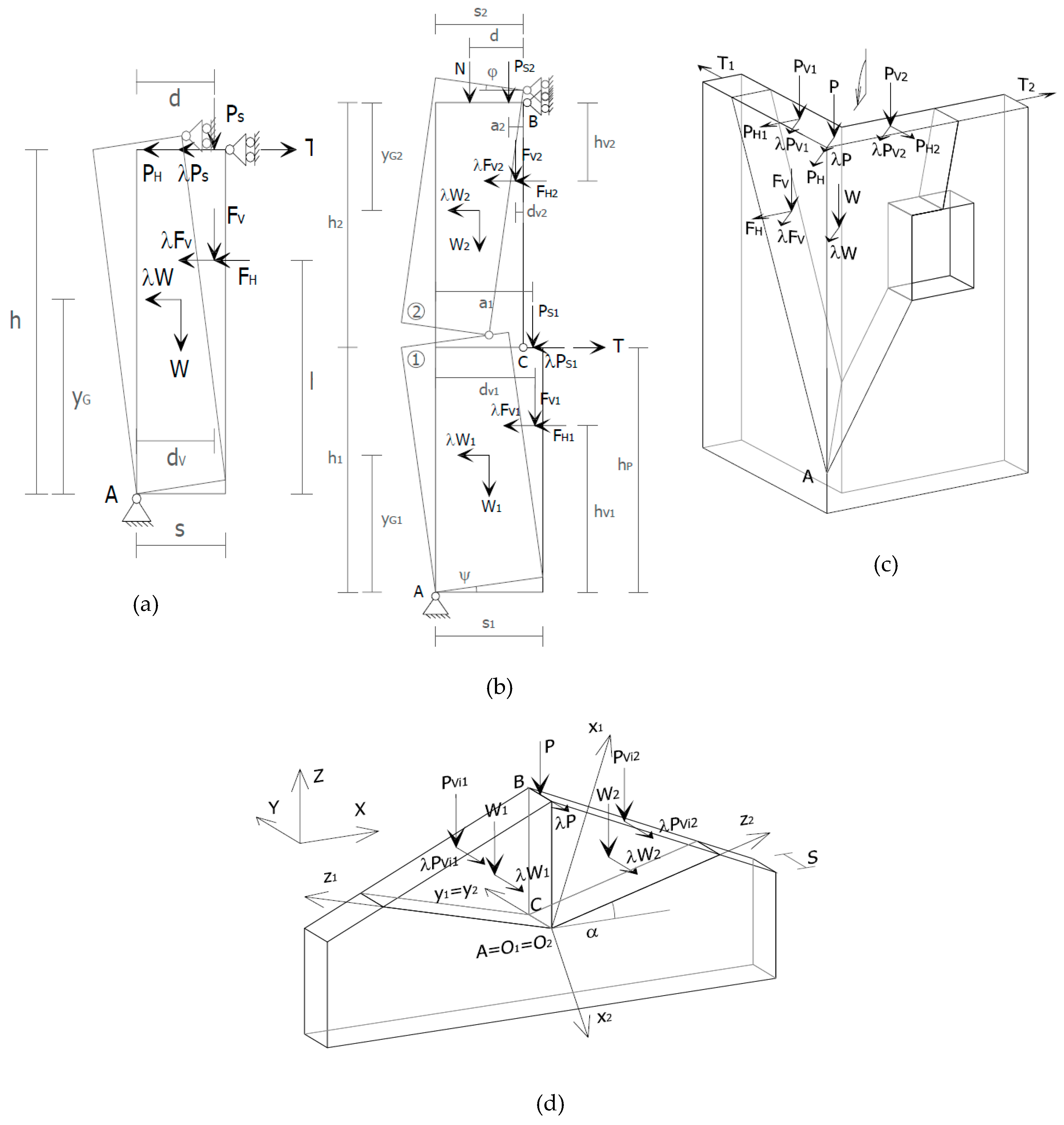
3.2. Façade Overturning
The façade overturning mechanism is activated by the out-of-plane rotation of the façade wall, which results in its detachment from the roof (
Figure 3a). The multiplier of the horizontal loads acting on macro-elements is evaluated as follows:
The causes responsible for the activation of this mechanism are no constraint at the top, no connection of the facade to the orthogonal walls, absence of metallic tie rods, deformable floors and presence of non-counteracted thrusts. When the mechanism is activated, vertical cracks on masonry, out-of-thumb of walls and beams extraction from floors can be observed. This mechanism can involve walls of one or more levels, as well as the entire thickness of the wall or only some part of it.
3.3. Vertical Bending Mechanism
This mechanism is activated by the formation of a horizontal cylindrical hinge, which divides the wall into two blocks. It is described by the reciprocal rotation of each block around an axis (
Figure 3b). The horizontal load multiplier acting on macro-elements is evaluated by the following equation:
where
The causes responsible for the activation of this mechanism are the lack of connection of the wall to orthogonal ones, excessive wall slenderness, masonry poor quality, horizontal localized thrusts and intermediate floors badly connected to the walls. When this mechanism is activated, out-of-thumb of walls, horizontal and vertical cracks and beams extraction from floors can be observed. This mechanism can involve walls of one or more levels, as well as the entire thickness of the wall or only a part of it.
3.4. Corner Overturning
This mechanism is activated by a rigid rotation of a wedge, delimited by fracture surfaces with diagonal patterns in the corners of walls (
Figure 3c), with respect to a hinge placed at the wall base. The multiplier of horizontal loads acting on macro-elements is evaluated as follows:
where
This mechanism is frequent in buildings with non-counteracted thrust corresponding with corners, due to loads transmitted by sloped roofs. The kinematic mechanism is defined by the rotation of the macro-element around an axis perpendicular to the vertical plane with an angle of 45°.
3.5. Roof Gable Overturning
This mechanism is activated by the out-of-plane overturning of the top part. The resulting crack is represented by an almost horizontal lesion (
Figure 3d). Horizontal multiplier of the loads acting on macro-elements is evaluated by the following equation:
The kinematic mechanism is usually caused by the cyclic hammering action of the roof ridge beam. In fact, the presence of large ridge beams causes a significant thrust to the churches wall top part, determining the detachment of cuneiform macro-elements.
3.6. Safety Checks
According to the Italian standards [
36,
37], the spectral acceleration (α
*0) which activates the mechanism is defined by the following equation [
35]:
where:
- −
M* is the participant mass, which can be evaluated considering the virtual displacement of application points of different weights (Pi). Indicated by (n+m) the number of P
i and by δ
xi the virtual horizontal displacement of i-th weight P
i application point, the participating mass is defined as
- −
is the gravity acceleration;
- −
FC is the confidence factor;
- −
α0 is the horizontal multiplier of loads.
In the case of either an isolated element or a building portion fixed to the ground, the seismic check is satisfied if the spectral acceleration (α*
0) activating the mechanism fulfils the following relationship:
where:
- −
a
g is the site acceleration, which is a function of both the exceeding probability referred to the ULS and the reference life, as defined in [
36];
- −
S is an amplification coefficient, given by the product between the stratigraphic amplification coefficient and the topographic one, both defined in [
36];
- −
q is the behaviour factor [
35,
36], which can be assumed as being equal to 2.0.
Instead, if the local mechanism involves a portion of the construction placed at a certain height, it should be considered that the absolute acceleration of the building portion involved by the kinematic mechanism is generally amplified with respect to the ground acceleration. An acceptable approximation consists of verifying, in addition to Equation (9), the following relationship:
where:
- −
Sg (T1) is the spectral acceleration at the ULS calculated in correspondence with the period T1;
- −
T1 is the vibration first period of the entire structure in the considered direction;
- −
Ψ (Z) is the first vibration mode displacement in the considered direction at a certain height, normalized to that at the building top; it can be assumed as Z/H, H being the entire structure height and Z the distance between the building foundation and the centroids of blocks affected by the mechanism;
- −
γ is the modal participation coefficient;
- −
q is the behaviour factor [
35,
36], which can be assumed as being equal to 2.0.
In this case, both checks described in Equations (9) and (10) must be satisfied. When checks performed according to the above formulas are not satisfied, a strengthening intervention must be designed and performed.
4. Parametric Analyses
4.1. Premise
The goal of parametric analyses is to identify the horizontal loads multiplier (α) trend by varying two geometrical features, namely thickness and height, of church walls. Exploiting
Table 3, a range of variable values of height and thickness can be identified for the execution of the two following parametric analyses types:
- −
Type A: average height is fixed and thickness is varied from the minimum value of 0.30 meters (minimum thickness of walls detected in other churches of Teramo not presented in the current work) to two meters, each time with an increase of 10 centimetres.
- −
Type B: average thickness is fixed and the total height is changed from the minimum value of three meters to the maximum height of 14 meters (maximum value detected in other churches of Teramo not presented in the current work), with an increasing step of 50 centimetres.
With reference to the coverage, timber (gable, truss and hipped) and masonry (barrel vaults and cross vaults) roofs are examined.
In order to obtain unfavourable results, a poor-quality masonry (disordered masonry with w = 19 KN/m3) is considered.
4.2. Façade Overturning
The considered mechanism is the same of a free wall subjected to overturning, but obviously the complexity level is much greater and depends on the construction geometric characteristics. In this section, the simple façade overturning without connections to the adjacent perpendicular walls is illustrated. Furthermore, the total overturning involving the entire wall is considered. Obviously, the kinematic mechanism also involves the vaults and/or the roofs supported by the wall that overturns, causing its collapse.
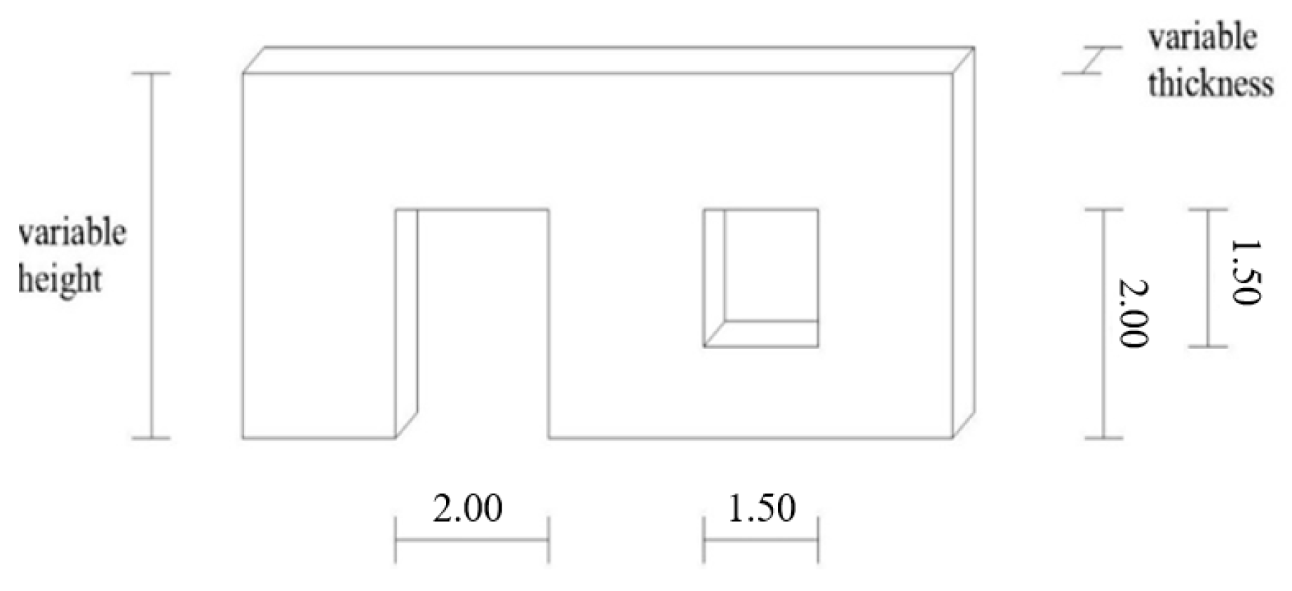
Figure 4 shows the geometrical features used for parametric analyses types A and B.
In parametric analysis type A, the church height is fixed to the value of 6.70 meters (average height, see
Table 2).
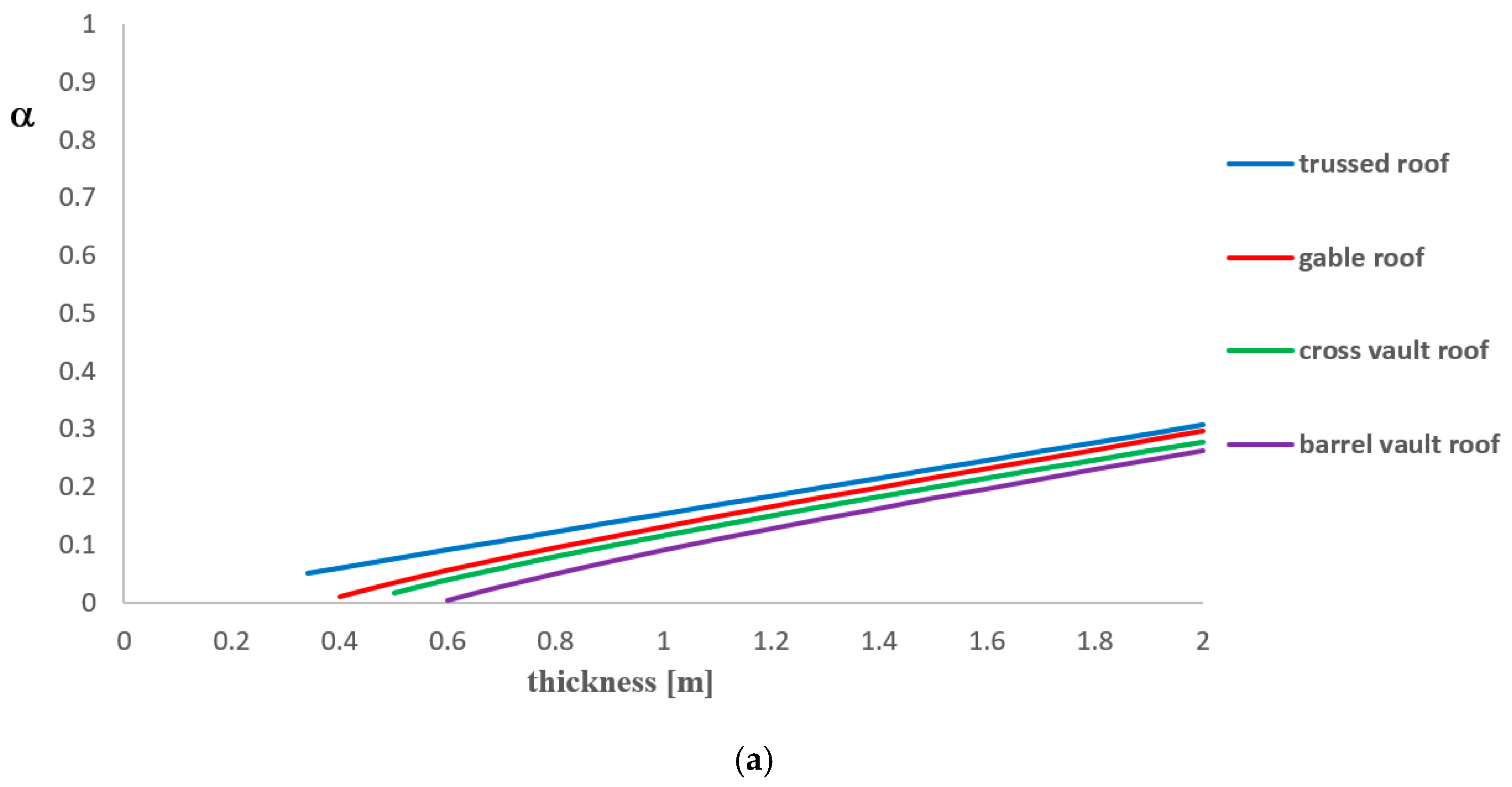
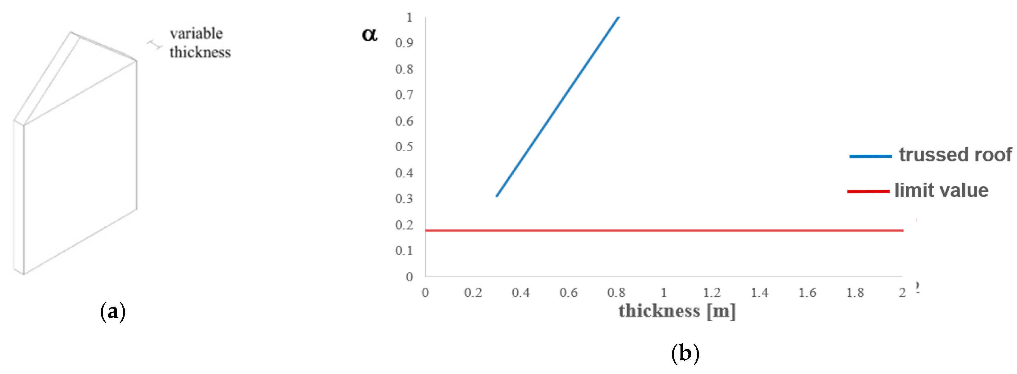
Figure 5a shows the parametric analysis results. It is observed that loads collapse multiplier increases in two cases; that is, when either thickness increases or the roof weight is reduced.
For each analysis, safety checks as described in
Section 3.6 are carried out. The analysis results are visible in
Figure 5b–e, where the limit value of α for the check satisfaction is represented with a horizontal red line, so that values below this line correspond to cases of unsatisfied checks. In particular, it is found that the limit values of α are 0.184 for trussed roofs, 0.166 for gable roofs, 0.167 for cross vault roofs and 0.163 for barrel vault roofs.
In the case considered, checks are not satisfied for thickness values lower than 1.10 meters for trussed roofs, lower than 1.30 meters for gable roofs and cross vault roofs and lower than 1.40 meters for barrel vault roofs. In these situations, a strengthening intervention must be designed in order to avoid the overturning mechanism of facades under earthquakes.
In parametric analysis type B, the church thickness is fixed to the value of 0.70 meters (average thickness, see
Table 2).
Figure 5a shows that the collapse multiplier increases when height decreases and roof weight reduces. For each analysis, the design checks according to the Italian standards (see
Section 3.6) are carried out. The limit values of α are 0.172 for trussed roofs, 0.171 for gable roofs, 0.160 for cross vault roofs and 0.156 for barrel vault roofs. From the analysis results, it is noticed that for a thickness value equal to 0.70 meters, most checks are not satisfied. For this reason, checks are repeated considering a minimum thickness value of 1.40 meters. The design check results considering different roof types are shown in
Figure 6b–e, where the red horizontal line represents the limit safety value. From the achieved results, it is observed that checks are not satisfied for height values lower than 8 meters for trussed roofs, 7.50 meters for gable roofs, 7.40 for cross vault roofs and 7.00 meters for barrel vault roofs. Therefore, in all these cases, an appropriate strengthening intervention should be planned in order to avoid the mechanism activation.
4.3. Vertical Bending Mechanism
Vertical bending of a continuous wall strip is herein considered. This strip belongs to the wall portion included between two subsequent floors, which is subjected to the kinematic mechanism. For this reason, required parameters should be evaluated considering a vertical masonry strip with unitary width under loads deriving from the influence area acting on it. In this way, the analysis considers all the possible positions of the cylindrical hinge along the wall height and indicates the one which the minimum value of the collapse multiplier corresponds to. In the case under study, a wall constrained to the top subjected to a mechanism affecting its whole thickness is hypothesized.
For parametric analysis, timber, cross vault and barrel vault roofs are considered.
In parametric analysis type A, the church height is fixed to the value of 6.70 meters.
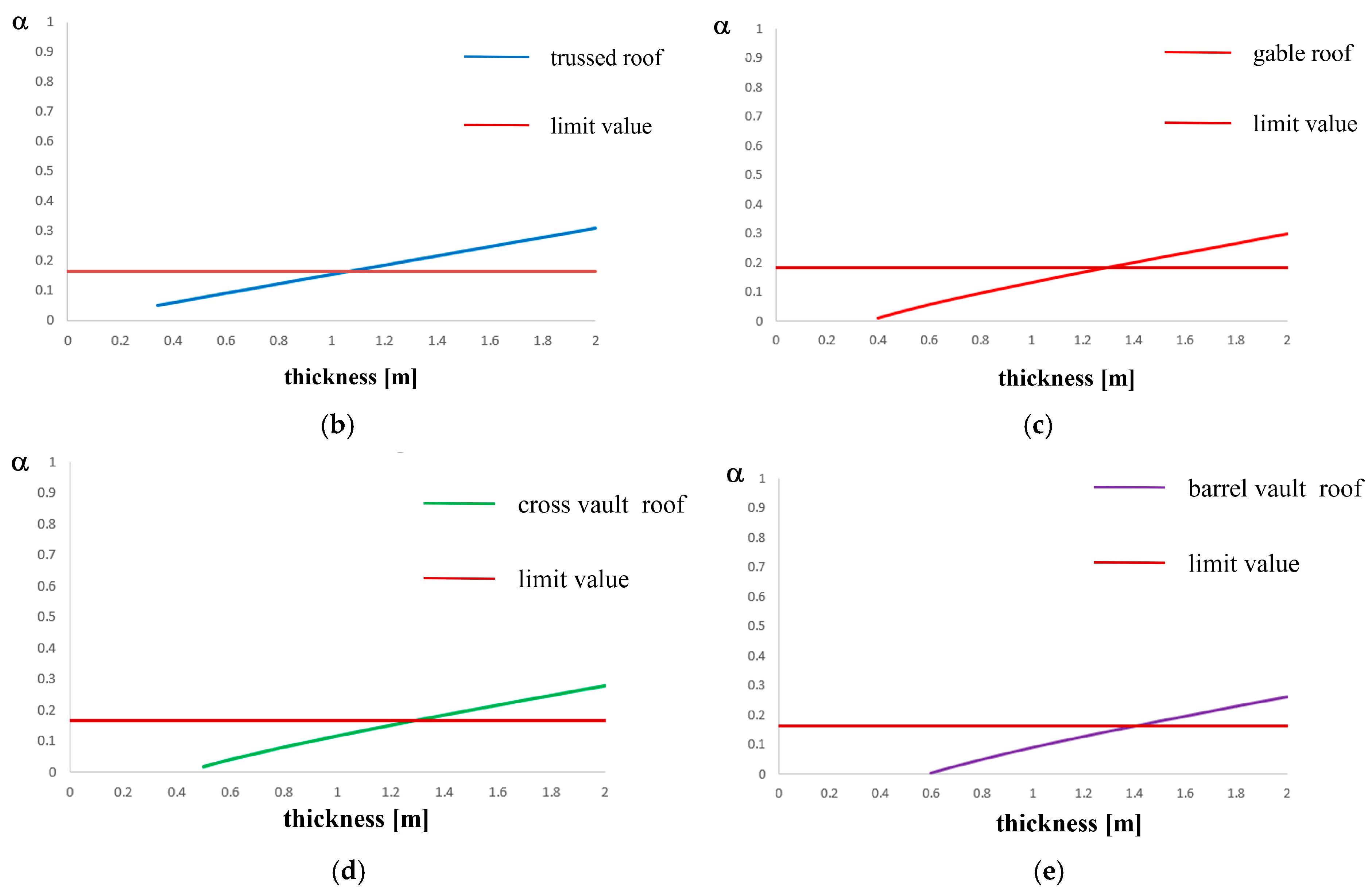
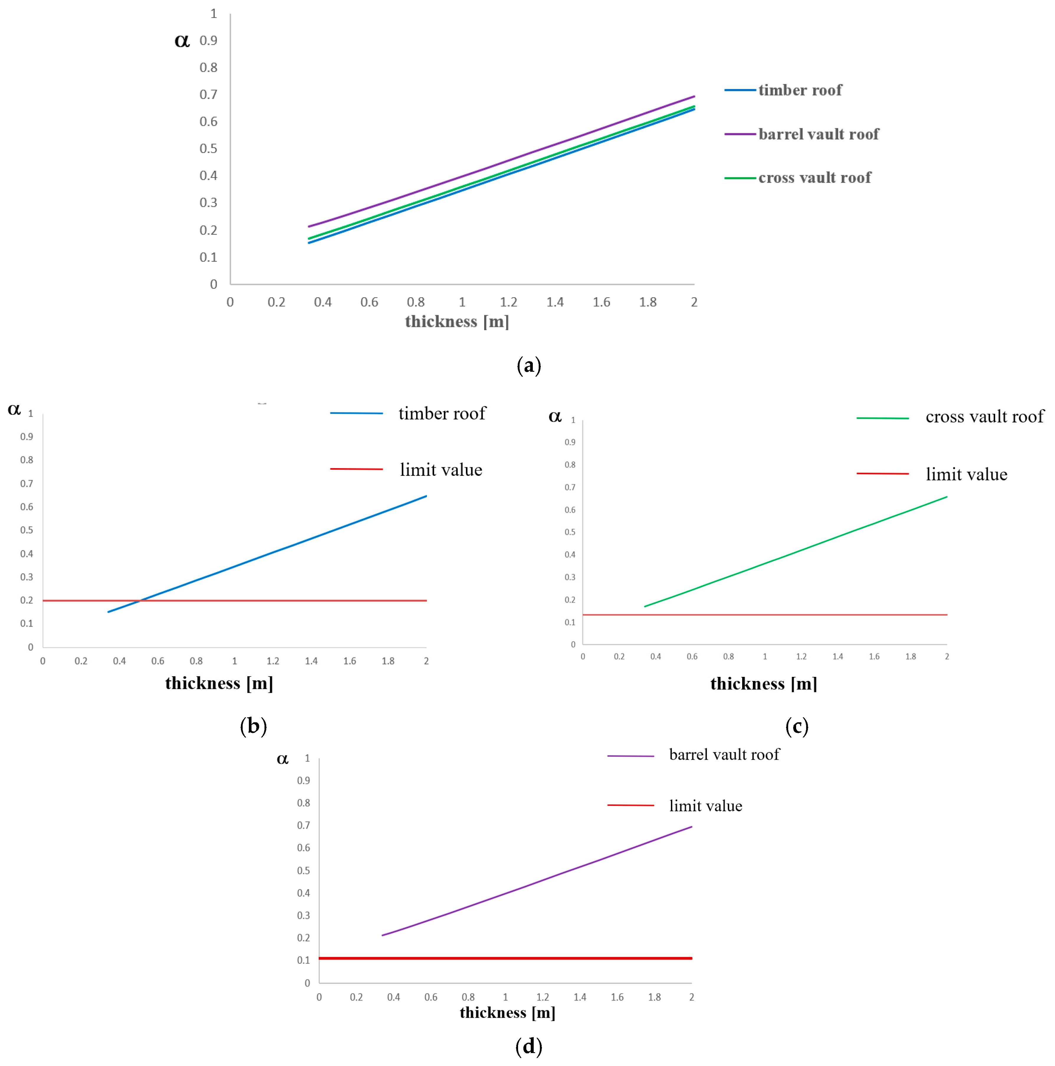
Figure 6a shows that collapse multiplier increases when both thickness and roof weight increase. Checks results are shown in
Figure 7b–d, where it is noticed that they are not satisfied only in the case of timber roof for thickness values lower than 0.50 meters. From the analyses carried out, it is achieved that the limit values of α are 0.199 for timber roofs, 0.133 for cross vault roofs and 0.11 for barrel vault roofs.
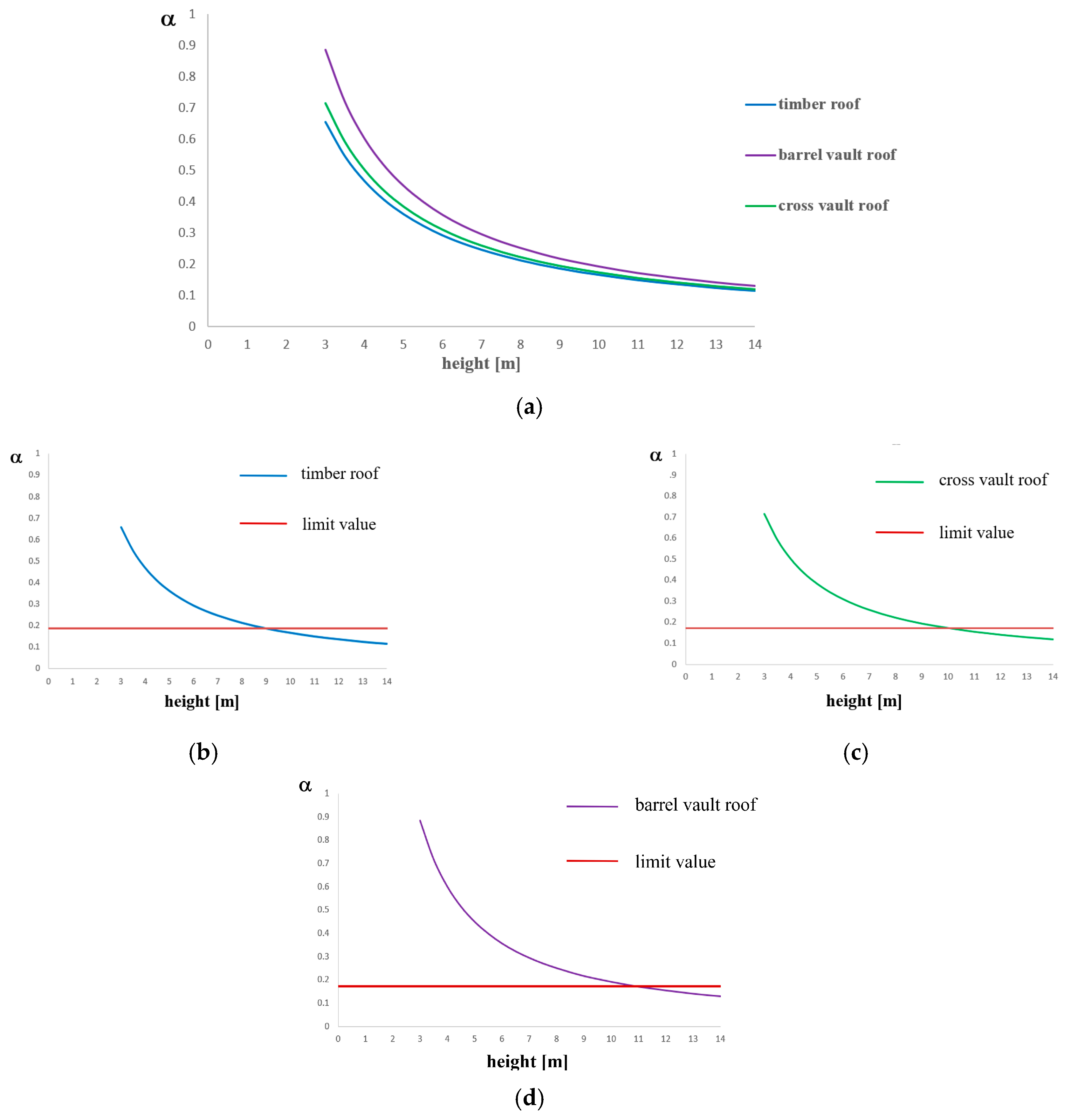
In parametric analysis type B, the church thickness is fixed to the value of 0.70 meters.
Figure 7a shows that the collapse multiplier increases when height decreases and roof weight increases. The limit values of α are 0.186 for timber roofs and 0.173 for cross vault roofs and barrel vault roofs. Design checks illustrated in
Figure 8b–d, where the allowable value of α is marked with a horizontal red line, are not satisfied for height values higher than 9.00 meters for timber roofs, higher than 10 meters for cross vault roofs and higher than 11.40 meters for barrel vault roofs.
4.4. Corner Overturning
This mechanism involves the building corner overturning, which is generally determined by the roof elements’ thrust. It is manifested through the rotation of a detachment wedge delimited by fracture surfaces in two walls orthogonal to each other. Rotation happens around a hinge placed at the wedge base.
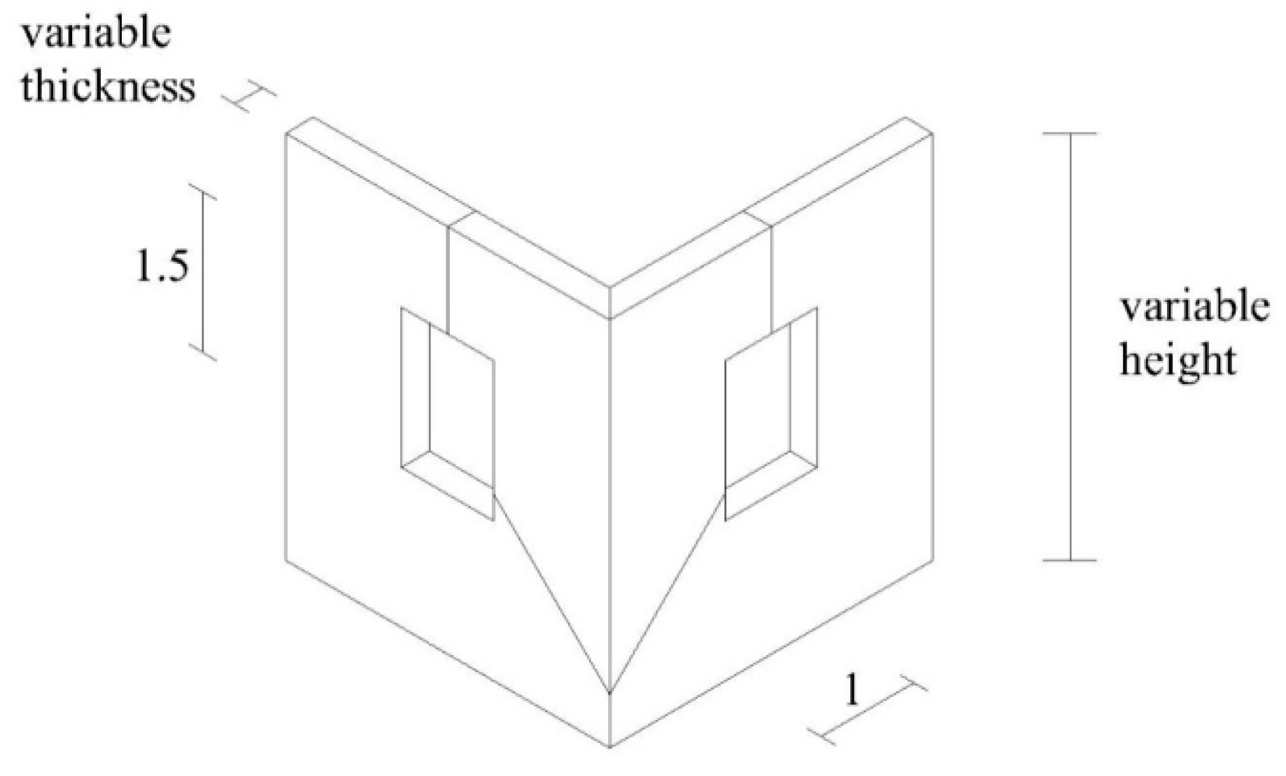
Figure 9 shows the geometrical features used for parametric analyses types A and B. Timber hipped and cross vault roofs are considered as church coverage. Even if timber hipped roofs are not detected in the studied churches, since they are both commonly used in this structural typology and strongly responsible of the activation of such a mechanism, they are taken into account to evaluate the load’s collapse multiplier evolution as the roof weight decreases. For this kind of analysis, a detachment wedge height is assumed to be equal to 50 centimetres.
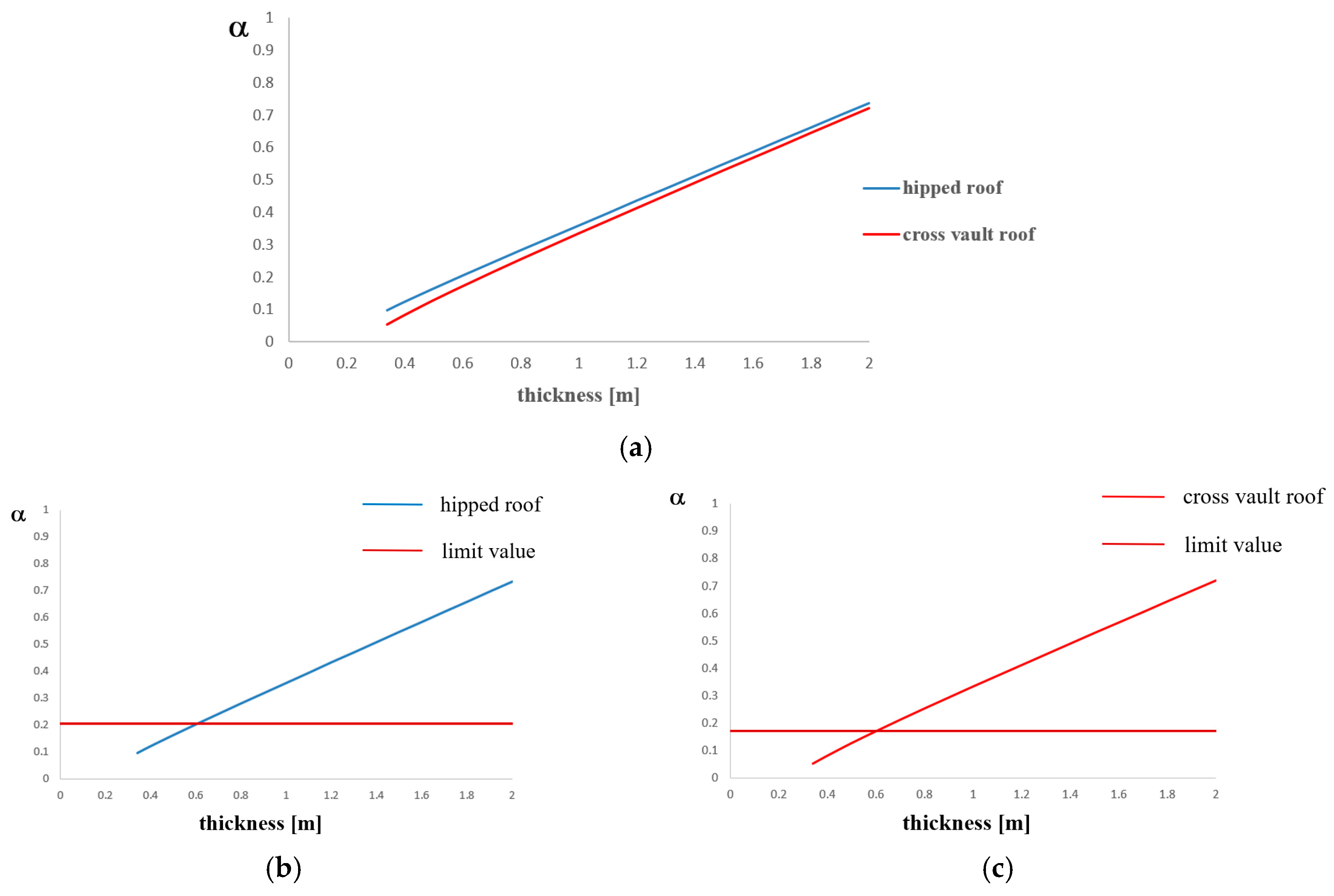
In parametric analysis type A, the church height is fixed to the value of 6.70 meters.
Figure 10a shows that the collapse multiplier increases when thickness increases and roof weight decreases. The limit values of α are 0.199 for timber roofs and 0.204 for cross vault roofs. Design checks reported in
Figure 10b,c are not satisfied for thickness values lower than 0.60 meters both for timber hipped roofs and cross vault roofs. This thickness limit value is obtained by the intersection of curves with the horizontal red line representing the allowable value of α.
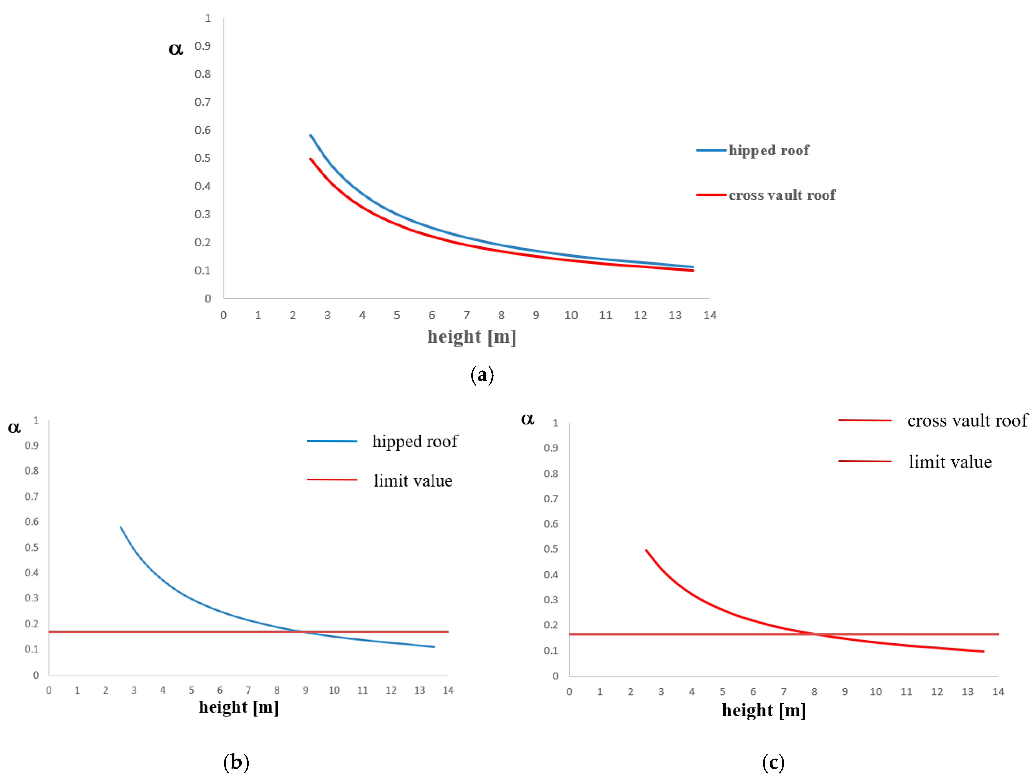
In parametric analysis type B, the church thickness is fixed to the value of 0.70 meters. In
Figure 11a it is noticed that the collapse multiplier increases when both height and roof weight decrease. In fact, a hipped roof has a lower weight than a cross vault one; when the roof weight decreases, the horizontal load multiplier increases, because the stabilizing bending moment decreases. Furthermore, if height decreases, the multiplier increases because the lever arm reduces. The limit values of α are 0.169 for timber roofs and 0.167 for cross vault roofs. In
Figure 11b,c, the results of design checks are reported together with horizontal red lines indicating the threshold value of the α factor. From the verification results, it is observed that safety is achieved not for height values higher than 9.00 meters for timber hipped roofs and higher than 8.00 meters for cross vault roofs.
4.5. Roof Gable Wall Overturning
The horizontal bending mechanism is characterized by the identification of cuneiform macro-elements, which rotate through oblique cylindrical hinges. This mechanism is due to the absence of adequate connections between the top part of the wall and roof elements. The kinematic mechanism is, therefore, caused by the hammering action that the roof beam exerts on the top part of the wall. For the roof gable wall overturning mechanism, timber trussed roofs are considered and the church height including the top part is fixed to the value of 7.10 meters.
Figure 12a shows the geometrical features of the roof gable wall used for parametric analysis. Analyses are carried out considering hinges without inclination in respect to the horizontal direction. The limit value of α is 0.176.
Figure 12b shows that the collapse multiplier increases when thickness increases and checks are always satisfied.
4.6. Final Remarks
The goal of parametric analyses is the determination, for each of the mechanisms analysed, of the limit values of both minimum thickness and maximum height of walls which satisfy seismic verifications. Parametric analyses results derived from considering all the roof types are presented in
Table 3.
On the basis of the obtained results, simple equations based on wall thickness and height only which allow for a quick evaluation of horizontal loads collapse multiplier can be formulated. Referring to
Figure 5, the proposed equations are:
Facade overturning mechanism—trussed roof (Figure 13a,b): Vertical bending mechanism: Roof gable wall mechanism (Figure 15):
where α is the collapse load multiplier, t is the wall thickness and h is the church height. Equations (11) to (14) are composed by two aliquots: the first (as function of the thickness) is the trend line that approximates the curve, i.e., a linear straight line with a correlation coefficient of 1; the second (6.70/h) is instead the correlation based on the height variation. Contrary to this, Equation (15) is composed by the first aliquot only. Compared to the formulation obtained through the linear kinematic analysis shown in the Italian standard [
35], the new equations herein proposed, that are of course valid only for the investigated churches, give slightly lower values, that allow one to operate in a more safe way.
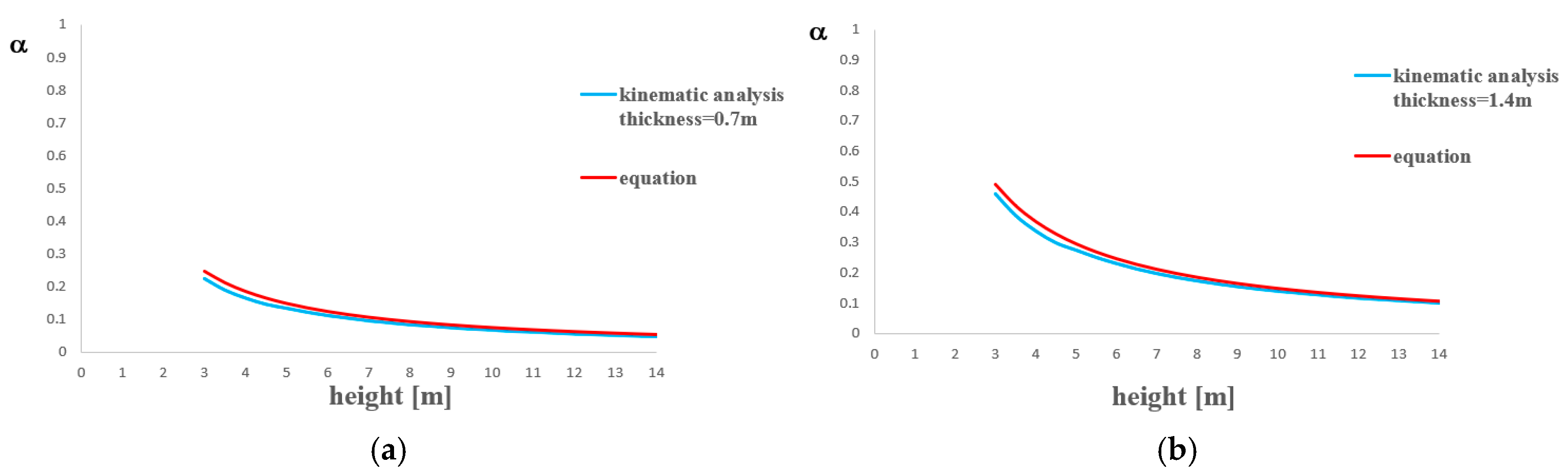
First, with reference to the façade overturning mechanism,
Figure 13 shows the comparison between the kinematic analysis curve of
Figure 6b and that from the corresponding Equation (11) for the two wall thicknesses of 0.70 m and 1.40 m. The proposed formulation values overestimate those obtained by the kinematic analysis by 5.2% to 8.9%.
Second, the comparison of curves dealing with the vertical bending mechanisms is depicted in
Figure 14. In particular, the comparisons are between the kinematic analysis curve of timber roofs (
Figure 8b) and the curve from Equation (12) (
Figure 14a), the kinematic analysis curve of cross vault roofs (
Figure 8c) and the curve from Equation (13) (
Figure 14b), and the kinematic analysis curve of barrel vault roofs (
Figure 8d) and the curve from Equation (14) (
Figure 14c). From the comparative study, it appears that the errors between the proposed formulations values and the kinematic analyses ones are in the following ranges:
- −
timber roof: from 1% to 19%;
- −
cross vault roof: from 1.9% to 23.8%;
- −
barrel vault roof from 1% to 31%.
In particular, it is observed that in all cases the errors increase as the church height augments. Finally,
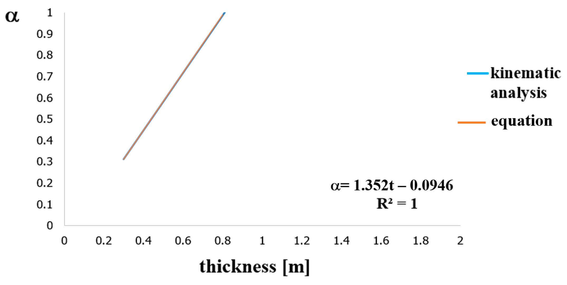
Figure 15 shows the roof gable overturning analysis, where it is noticed that the trend of Equation (15) is a straight line with a correlation coefficient equal to one, which means that it perfectly fits the kinematic analysis results.
5. Conclusions
In this paper, local collapse mechanisms related to the out-of-plane wall response of masonry churches have been investigated. The performed research work has been conducted on 12 masonry churches located in Teramo (Italy), whose main local collapse mechanisms, namely facade overturning, vertical bending, corner overturning and roof gable wall overturning, have been inspected.
Parametric analyses have been carried out through linear kinematic analyses by considering the variation of the most significant geometrical parameters of the walls of churches, namely thickness and height. For each local mechanism, the collapse load multiplier has been evaluated and the spectral acceleration activating that mechanism has been assessed in order to conduct the safety checks foreseen by the Italian standards. Two kinds of parametric analysis have been developed: in the first case (Type A), the average height has been fixed and the thickness has been augmented up to two meters, with an increasing step of 10 cm, while in the second case (Type B), the average thickness has been fixed and the height has been varied from 3 to 10 m, with an increasing step of 0.50 m. From the analyses performed, the following results are obtained:
Façade overturning mechanism: churches with trussed, gable, cross vault and barrel vault roofs have been considered. Type A analyses checks were not satisfied for thickness values lower than 1.10 m for trussed roofs, lower than 1.30 m for gable and cross vault roofs and lower than 1.40 m for barrel vault roofs. Meanwhile, type B analyses checks were not satisfied for height values lower than 8 m for trussed roofs, 7.50 m for gable roofs, 7.40 m for cross vault roofs and 7.00 m for barrel vault roofs.
Vertical bending mechanism: timber, cross vault and barrel vault roofs have been considered. Type A analyses checks were not satisfied only in the case of timber roof for thickness values lower than 0.50 m. Type B analyses checks were not satisfied for height values higher than 9.00 m for timber roofs, higher than 10 m for cross vault roofs and higher than 11.40 m for barrel vault roofs.
Corner overturning: hipped and cross vault roofs have been considered. Type A analyses checks were not satisfied for thickness values lower than 0.60 m both for timber hipped roofs and cross vault roofs. Type B analyses checks were not satisfied for height values higher than 9.00 m for timber hipped roofs and higher than 8.00 m for cross vault roofs.
Roof gable wall overturning: according to what was detected in situ, only timber trussed roofs were considered and the church height, including the top part, was fixed to the value of 7.10 m. Seismic checks were always satisfied.
In order to better highlight the study results, appropriate curves correlating the horizontal loads multiplier to the thickness (type A analysis) and the height (type B analysis) of church walls have been plotted. Finally, five equations are proposed on which a quick prediction of the horizontal multiplier loads can be done. These formulations give slightly higher values that allow one to operate in a safer way.
The goal of these parametric analyses has been the determination, for a specific Italian area (district of Teramo) characterized by the same high seismicity and for each of the mechanisms analysed, of the limit values of both minimum thickness and maximum height of walls able to satisfy seismic verifications. In particular, the minimum thickness has been to be found variable from 0.30 m (roof gable wall overturning) to 1.50 m (facade overturning), while the maximum height has been framed in the interval from 1.10 (roof gable wall overturning) to 9.00 m (vertical bending).
The proposed procedure can represent a very effective seismic analysis tool, since without making refined analyses but through the consultation of diagrams and equations only, it is possible to discover the masonry churches’ vulnerabilities towards local collapse mechanisms activated by earthquakes. In addition, by assessing the horizontal multiplier loads and the safety degree against the activation of possible local collapse mechanisms, it is possible to classify the churches according to the priority of upgrading interventions required.
The future development of this research will undoubtedly foresee the application of the proposed procedure to other church samples with different geometrical characteristics and located in areas with different seismic hazard levels. Furthermore, the procedure can also be extended to other monumental buildings, such as palaces and castles.
Author Contributions
Conceptualization, A.F.; Methodology, A.F.; Validation, A.F.; Investigation, G.V.; Data Curation, G.V.; Writing-Original Draft Preparation, G.V.; Writing-Review & Editing, F.F.; Supervision, A.F. All authors have read and agreed to the published version of the manuscript.
Funding
This research received no external funding.
Conflicts of Interest
The authors declare no conflict of interest.
References
- Milano, L.; Mannella, A.; Morisini, C.; Martinelli, A. Illustrated schedules of the main local collapse mechanisms in existing masonry buildings and the related kinematic analysis models (in Italian). Guidelines for the repair and strengthening of structural elements, infills and partitions, ReLUIS. 2009. Available online: http://www.reluis.it/doc/emergenza_terremoto_abruzzo/Schede_Meccanismi.pdf (accessed on 31 March 2020).
- Decree No.10 of 25/1/2006. Analysis of local collapse mechanisms in existing masonry buildings (in Italian). In Repertoire of Damage Mechanisms, Intervention Techniques and Related Costs in Masonry Buildings, Research Carried out as Part of an Agreement between the Marche Region; The University of L’Aquila and CNR-ITC: Molise region, Italy, 2006. [Google Scholar]
- Livesley, R.K. Limit analysis of structures formed from rigid blocks. Int. J. Numer. Methods Eng. 1978, 12, 1853–1871. [Google Scholar] [CrossRef]
- Begg, D.W.; Fishwick, R.J. Numerical analysis of rigid block structures including sliding. Comp. Meth. Struct. Masonry 1995, 3, 177–183. [Google Scholar]
- Baggio, C.; Trovalusci, P. Collapse behaviour of three-dimensional brick-block systems using non-linear programming. Struct. Eng. Mech. 2000, 10, 181–195. [Google Scholar] [CrossRef]
- De Felice, G.; Giannini, R. Out-of-plane seismic resistance of masonry walls. J. Earthq. Eng. 2001, 5, 253–271. [Google Scholar] [CrossRef]
- Ferris, M.; Tin-Loi, F. Limit analysis of frictional block assemblies as a mathematical program with complementarily constraints. Int. J. Mech. Sci. 2001, 43, 209–224. [Google Scholar] [CrossRef]
- Formisano, A. Local- and global-scale seismic analyses of historical masonry compounds in San Pio delle Camere (L’Aquila, Italy). Nat. Hazards 2017, 86, 465–487. [Google Scholar] [CrossRef]
- D’Ayala, D.; Speranza, E. Definition of collapse mechanisms and seismic vulnerability of masonry structures. Earthq. Spectra 2003, 19, 479–509. [Google Scholar] [CrossRef]
- Ferrante, A.; Clementi, F.; Milani, G. Advanced numerical analyses by the Non-Smooth Contact Dynamics method of an ancient masonry bell tower. Math. Methods Appl. Sci. 2020. [Google Scholar] [CrossRef]
- Clementi, F.; Ferrante, A.; Giordano, E.; Dubois, F.; Lenci, S. Damage assessment of ancient masonry churches stroked by the Central Italy earthquakes of 2016 by the non-smooth contact dynamics method. Bull. Earthq. Eng. 2020, 18, 455–486. [Google Scholar] [CrossRef]
- Orduňa, A.; Lourenço, P.B. Three-dimensional limit analysis of rigid blocks assemblages. Part I: Torsion failure on frictional interfaces and limit formulation. Int. J. Sol. Struct. 2005, 42, 5140–5160. [Google Scholar] [CrossRef]
- Calderini, C.; Lagomarsino, S. A continuum model for in-plane anisotropic inelastic behaviour of masonry. J. Struct. Eng. 2008, 134, 209–220. [Google Scholar] [CrossRef]
- Milani, G.; Lourenço, P.B.; Tralli, A. Homogenised limit analysis of masonry walls, Part I: Failure surfaces; Part II: Structural examples. Comput. Struct. 2006, 84, 166–195. [Google Scholar] [CrossRef]
- Massart, T.J.; Peerlings, R.H.J.; Geers, M.G.D. Mesoscopic modelling of failure and damage induced anisotropy in brick masonry. Eur. J. Mech. A Solid. 2004, 23, 719–735. [Google Scholar] [CrossRef]
- Cecchi, A.; Sab, K. Discrete and continuous models for in plane loaded random elastic brickwork. Eur. J. Mech. A Solid. 2008. [Google Scholar] [CrossRef]
- Brasile, S.; Casciaro, R.; Formica, G. Multilevel approach for brick masonry walls part II: On the use of equivalent continua. Comput. Method. Appl. Mech. Eng. 2008, 196, 4801–4810. [Google Scholar] [CrossRef]
- Formisano, A.; Vaiano, G.; Fabbrocino, F.; Milani, G. Seismic vulnerability of Italian masonry churches: The case of the Nativity of Blesses Virgin Mary in Stellata of Bondeno. J. Build. Eng. 2018, 20, 179–200. [Google Scholar] [CrossRef]
- Formisano, A.; Di Lorenzo, G.; Krstevska, L.; Landolfo, R. Fem Model Calibration of Experimental Environmental Vibration Tests on Two Churches Hit by L’Aquila Earthquake. Int. J. Archit. Herit. 2020. [Google Scholar] [CrossRef]
- Di Lorenzo, G.; Formisano, A.; Krstevska, L.; Landolfo, R. Ambient vibration test and numerical investigation on the St. Giuliano church in Poggio Picenze (L’aquila, Italy). J. Civ. Struct. Health Monit. 2019, 9, 477–490. [Google Scholar] [CrossRef]
- Fabbrocino, F.; Vaiano, G.; Formisano, A.; D’Amato, M. Large-scale seismic vulnerability and risk of masonry churches in seismic-prone areas: Two territorial case studies. Front. Built Environ. 2019, 5, 102. [Google Scholar] [CrossRef]
- Fabbrocino, F.; Vaiano, G.; Formisano, A. Parametric analysis on local collapse mechanisms of masonry churches. AIP Conf. Proc. 2019, 2116, 420003. [Google Scholar] [CrossRef]
- Formisano, A.; Milani, G. Seismic vulnerability analysis and retrofitting of the SS. Rosario church bell tower in Finale Emilia (Modena, Italy). Front. Built Environ. 2019, 5, 70. [Google Scholar] [CrossRef]
- D’Amato, M.; Formisano, A.; Gigliotti, R.; Laguardia, R. Simplified seismic analysis of ancient churches at a territorial scale. COMPDYN Proc. 2019, 1, 1382–1390. [Google Scholar]
- Giordano, E.; Ferrante, A.; Clementi, F.; Milani, G.; Formisano, A. Cultural Heritage and earthquake: The case study of San Francesco’s church in Amandola (Central Italy). In Proceedings of the 2019 IMEKO TC4 International Conference on Metrology for Archaeology and Cultural Heritage, MetroArchaeo 2019, Florence, Italy, 4–6 December 2019; pp. 37–42. [Google Scholar]
- Ferrante, A.; Giordano, E.; Clementi, F.; Milani, G.; Formisano, A. The Non-smooth tale of “Apennine Churches” stroked by the Central Italy Earthquakes of 2016. In Proceedings of the 2019 IMEKO TC4 International Conference on Metrology for Archaeology and Cultural Heritage, MetroArchaeo 2019, Florence, Italy, 4–6 December 2019; pp. 31–36. [Google Scholar]
- Casapulla, C.; Ceroni, F.; Formisano, A.; Salzano, P.; Prota, A. 2017 Ischia earthquake: Macroscale typological and damage assessment of masonry churches. COMPDYN Proc. 2019, 1, 1482–1500. [Google Scholar]
- Formisano, A.; Ciccone, G.; Mele, A. Large scale seismic vulnerability and risk evaluation of a masonry churches sample in the historical centre of Naples. AIP Conf. Proc. 2017, 1906, 090003. [Google Scholar] [CrossRef]
- Krstevska, L.; Tashkov, L.; Naumovski, N.; Florio, G.; Formisano, A.; Fornaro, A.; Landolfo, R. In-situ experimental testing of four historical buildings damaged during the 2009 L’Aquila earthquake. In Proceedings of the COST ACTION C26: Urban Habitat Constructions under Catastrophic Events—Proceedings of the Final Conference, Naples, Italy, 16–18 September 2010; pp. 427–432. [Google Scholar]
- Diaz Fuentes, D.; Baquedano Julia’, P.A.; D’Amato, M.; Laterza, M. Preliminary Seismic Damage Assessment of Mexican Churches after September 2017 Earthquakes. Int. J. Archit. Herit. 2019. [Google Scholar] [CrossRef]
- Lopez, S.; D’Amato, M.; Ramos, L.; Laterza, M.; Lourenço, P.B. Simplified formulation for estimating the main frequencies of ancient masonry churches. Front. Built Environ. 2019, 5, 18. [Google Scholar] [CrossRef]
- Ramírez, E.; Lourenço, P.B.; D’Amato, M. Seismic Assessment of the Matera Cathedral. RILEM Bookseries, 18. In Proceedings of the 11th International Conference on Structural Analysis of Historical Constructions (SAHC 2018), Cusco, Perù, 11–13 September 2018; pp. 1346–1354. [Google Scholar]
- Diaz Fuentes, D.; Laterza, M.; D’Amato, M. Seismic Vulnerability and Risk Assessment of Historic Constructions: The Case of Masonry and Adobe Churches in Italy and Chile. RILEM Bookseries, 18. In Proceedings of the 11th International Conference on Structural Analysis of Historical Constructions (SAHC 2018), Cusco, Perù, 11–13 September 2018; pp. 1127–1137. [Google Scholar]
- EN 1998-3. Eurocode 8: Design of Structures for Earthquake Resistance—Part 3: Assessment and Retrofitting of Buildings. European Committee for Standardisation: Brussels, Belgium, 2005. [Google Scholar]
- DPCM - Decree of the Minister Council President of the Italian Republic. Guidelines for the Seismic Risk Evaluation and Reduction of Cultural Heritage with Reference to the Constructions Technical Standards Referred to Decree of the M.I.T. 9 February 2011 (in Italian); Official Gazette: Rome, Italy, 2011. [Google Scholar]
- Ministry of Infrastructures and Transports. Ministerial Decree n. 17 January 2018 Updating of Technical codes for constructions (in Italian); Official Gazette: Rome, Italy, 2018. [Google Scholar]
- Ministry of Infrastructures and Transports. Ministerial Circular 11 February 2019 n. 7 Application instructions of the Updating of technical codes for constructions (in Italian); Official Gazette: Rome, Italy, 2019. [Google Scholar]
Figure 1.
Location of churches investigated in the city of Teramo.
Figure 1.
Location of churches investigated in the city of Teramo.
Figure 2.
External and internal views and plan layouts of churches investigated in the city of Teramo.
Figure 2.
External and internal views and plan layouts of churches investigated in the city of Teramo.
Figure 3.
Calculation schemes of the main collapse mechanisms: facade overturning (a), vertical bending (b), corner overturning (c) and roof gable wall overturning (d).
Figure 3.
Calculation schemes of the main collapse mechanisms: facade overturning (a), vertical bending (b), corner overturning (c) and roof gable wall overturning (d).
Figure 4.
Geometrical features (dimensions in meters) of the facade for overturning mechanism analysis.
Figure 4.
Geometrical features (dimensions in meters) of the facade for overturning mechanism analysis.
Figure 5.
Type A parametric analysis results for facade overturning mechanism (a) and design checks for trussed (b), gable (c), cross vault (d) and barrel vault (e) roofs.
Figure 5.
Type A parametric analysis results for facade overturning mechanism (a) and design checks for trussed (b), gable (c), cross vault (d) and barrel vault (e) roofs.
Figure 6.
Type B parametric analysis results for facade overturning mechanism (a) and design checks for trussed (b), gable (c), cross vault (d) and barrel vault (e) roofs.
Figure 6.
Type B parametric analysis results for facade overturning mechanism (a) and design checks for trussed (b), gable (c), cross vault (d) and barrel vault (e) roofs.
Figure 7.
Type A parametric analysis results for vertical bending mechanism (a) and design checks for timber (b), cross vault (c) and barrel vault (d) roofs.
Figure 7.
Type A parametric analysis results for vertical bending mechanism (a) and design checks for timber (b), cross vault (c) and barrel vault (d) roofs.
Figure 8.
Type B parametric analysis results for vertical bending mechanism (a) and design checks for timber (b), cross vault (c) and barrel vault (d) roofs.
Figure 8.
Type B parametric analysis results for vertical bending mechanism (a) and design checks for timber (b), cross vault (c) and barrel vault (d) roofs.
Figure 9.
Geometrical features of walls for corner overturning mechanism.
Figure 9.
Geometrical features of walls for corner overturning mechanism.
Figure 10.
Type A parametric analysis results for angle overturning mechanism (a) and design checks for timber hipped (b) and cross vault (c) roofs.
Figure 10.
Type A parametric analysis results for angle overturning mechanism (a) and design checks for timber hipped (b) and cross vault (c) roofs.
Figure 11.
Type B parametric analysis results for angle overturning mechanism (a) and design checks for timber hipped (b) and cross vault (c) roofs.
Figure 11.
Type B parametric analysis results for angle overturning mechanism (a) and design checks for timber hipped (b) and cross vault (c) roofs.
Figure 12.
Roof gable wall overturning mechanism: geometrical features (a) and results of design checks (b).
Figure 12.
Roof gable wall overturning mechanism: geometrical features (a) and results of design checks (b).
Figure 13.
Wall overturning mechanism of churches with trussed roof: comparison between kinematic analysis curve and analytical formula one for thickness of 0.70 (a) and 1.40 m (b).
Figure 13.
Wall overturning mechanism of churches with trussed roof: comparison between kinematic analysis curve and analytical formula one for thickness of 0.70 (a) and 1.40 m (b).
Figure 14.
Vertical bending mechanism: comparison between kinematic analysis curve and analytical formula one for churches with a timber roof (a), cross vault roof (b) and barrel vault roof (c).
Figure 14.
Vertical bending mechanism: comparison between kinematic analysis curve and analytical formula one for churches with a timber roof (a), cross vault roof (b) and barrel vault roof (c).
Figure 15.
Roof gable wall overturning mechanism: comparison between kinematic analysis curve and analytical formula one.
Figure 15.
Roof gable wall overturning mechanism: comparison between kinematic analysis curve and analytical formula one.
Table 1.
Geometrical dimensions of studied churches.
Table 1.
Geometrical dimensions of studied churches.
| Church | Hall | Apse | Bell Tower |
|---|
| Major Side [m] | Minor Side [m] | Average Height [m] | Major Side [m] | Minor Side [m] | Average Height [m] | yes/no | Estimated Height [m] |
|---|
| St. John | 16.50 | 14.30 | 10.00 | - | no | - |
| St. Anastasio | 14.70 | 7.20 | 6.70 | 7.50 | 3.50 | 7.15 | yes | 10.00 |
Holy Mary of
Carmine | 11.30 | 6.20 | 7.20 | 6.45 | 5.00 | 7.00 | yes | 15.00 |
| St. Nicola | 11.00 | 4.60 | 3.50 | - | no | - |
| St. Catherine | 13.40 | 6.50 | 7.50 | - | no | - |
| St. Luca | 8.00 | 4.00 | 6.00 | - | no | - |
St. Mary de
Praediis | 14.50 | 9.00 | 5.00 | 3.00 | 1.50 | 5.00 | no | - |
| St. Michael Arch. | 16.20 | 5.30 | 5.00 | - | no | - |
| St. Francis of Assisi | 11.40 | 7.00 | 7.80 | 5.85 | 5.80 | 6.00 | yes | 13.00 |
| St. John In Pergulis | 14.90 | 9.30 | 8.00 | - | yes | 12.90 |
| Most Holy Salvatore | 10.70 | 7.20 | 8.00 | - | yes | 18.00 |
| St. Stephan | 14.40 | 5.25 | 5.85 | 3.40 | 5.25 | 3.50 | yes | 15.00 |
Table 2.
Main geometrical features of walls of studied churches.
Table 2.
Main geometrical features of walls of studied churches.
| Church | Thickness [m] | Height [m] | Average Height [m] | Maximum Height [m] |
| St. John | 1.0 | 10.0 | 6.7 | 10.0 |
| St. Anastasio | 1.0 | 6.5 |
| Holy Mary of Carmine | 0.6 | 7.2 |
| St. Nicola | 0.5 | 3.5 |
| St. Catherine | 1.0 | 7.5 |
| St. Luca | 0.5 | 6.0 | Minimum Thickness [m] | Average Thickness [m] |
| St. Mary de Praediis | 0.5 | 5.0 | 0.5 | 0.7 |
| St. Michael Archangel | 0.5 | 5.0 |
| St. Francis of Assisi | 0.5 | 7.8 |
| St. John In Pergulis | 0.7 | 8.0 |
| Most Holy Salvatore | 0.6 | 8.0 |
| St. Stephan | 1.0 | 5.8 |
Table 3.
Limit values of geometrical dimensions of church walls satisfying seismic checks.
Table 3.
Limit values of geometrical dimensions of church walls satisfying seismic checks.
| Collapse Mechanism | Minimum Thickness [m] | Maximum Height [m] |
|---|
| Facade overturning | 1.50 | 7.00 |
| Vertical Bending | 0.50 | 9.00 |
| Corner overturning | 0.60 | 7.50 |
| Roof gable wall overturning | 0.30 | 1.10 |
© 2020 by the authors. Licensee MDPI, Basel, Switzerland. This article is an open access article distributed under the terms and conditions of the Creative Commons Attribution (CC BY) license (http://creativecommons.org/licenses/by/4.0/).


