Ground Penetrating Radar Investigation of Corvin Castle (Castelul Corvinilor), Hunedoara, Romania


Abstract
1. Introduction
1.1. Historical Background
1.2. Nondestructive Methods
Ground Penetrating Radar
1.3. Objectives
2. Materials and Methods
2.1. Data Collection
2.2. Processing
2.3. Sources
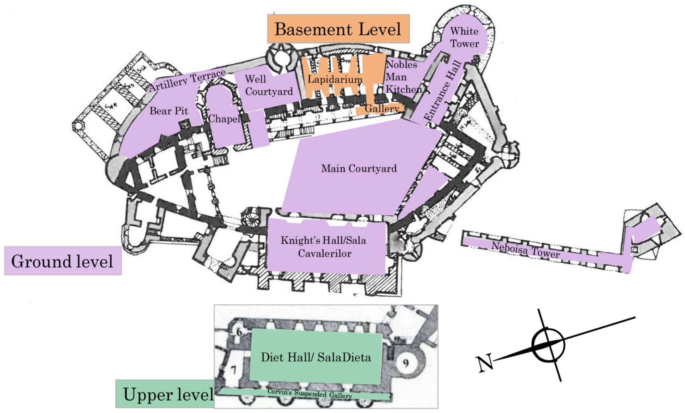
2.4. Summary of Scanned Areas
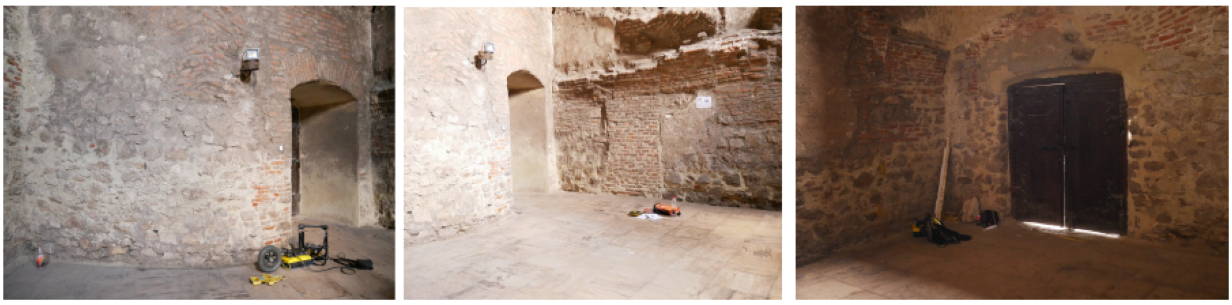
2.4.1. Noble’s Man Kitchen (Bucataria Nobiliara)
2.4.2. White Tower and Entrance Hall (Bastionul Alb and Turnul vechi de poarta)
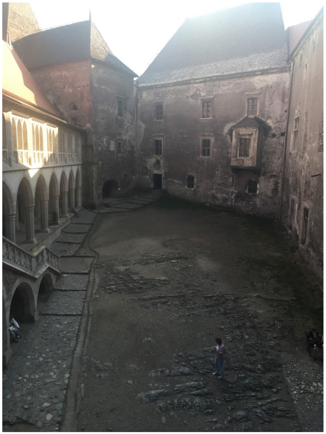
2.4.3. Courtyard (Curtea)
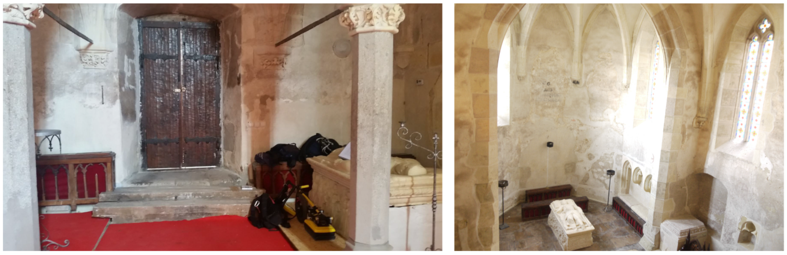
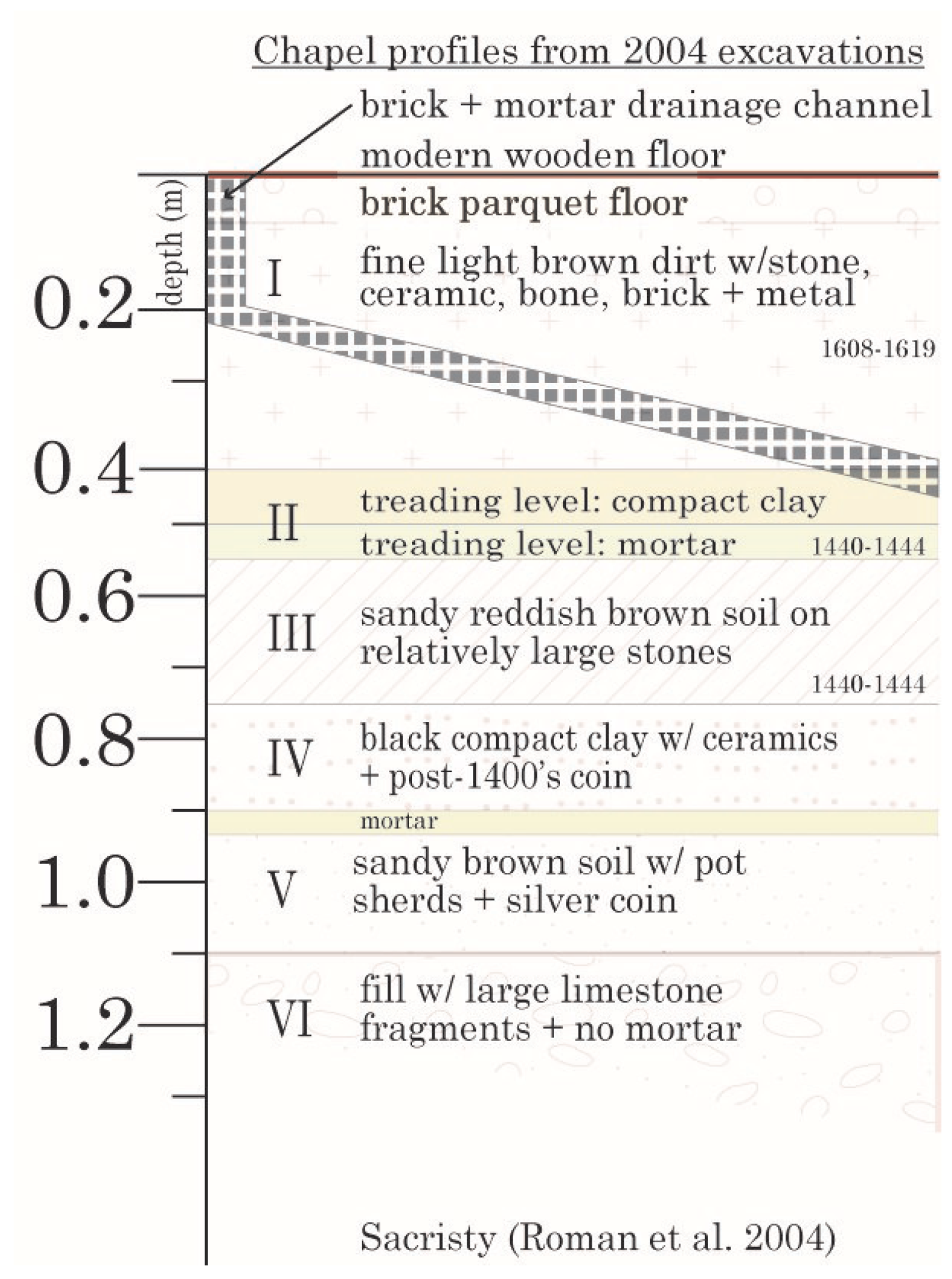
2.4.4. Chapel Complex (Capella and Sacristy or Complexul Ecleziastic)
2.4.5. Neboisa Tower (Turnul Njeboisia)
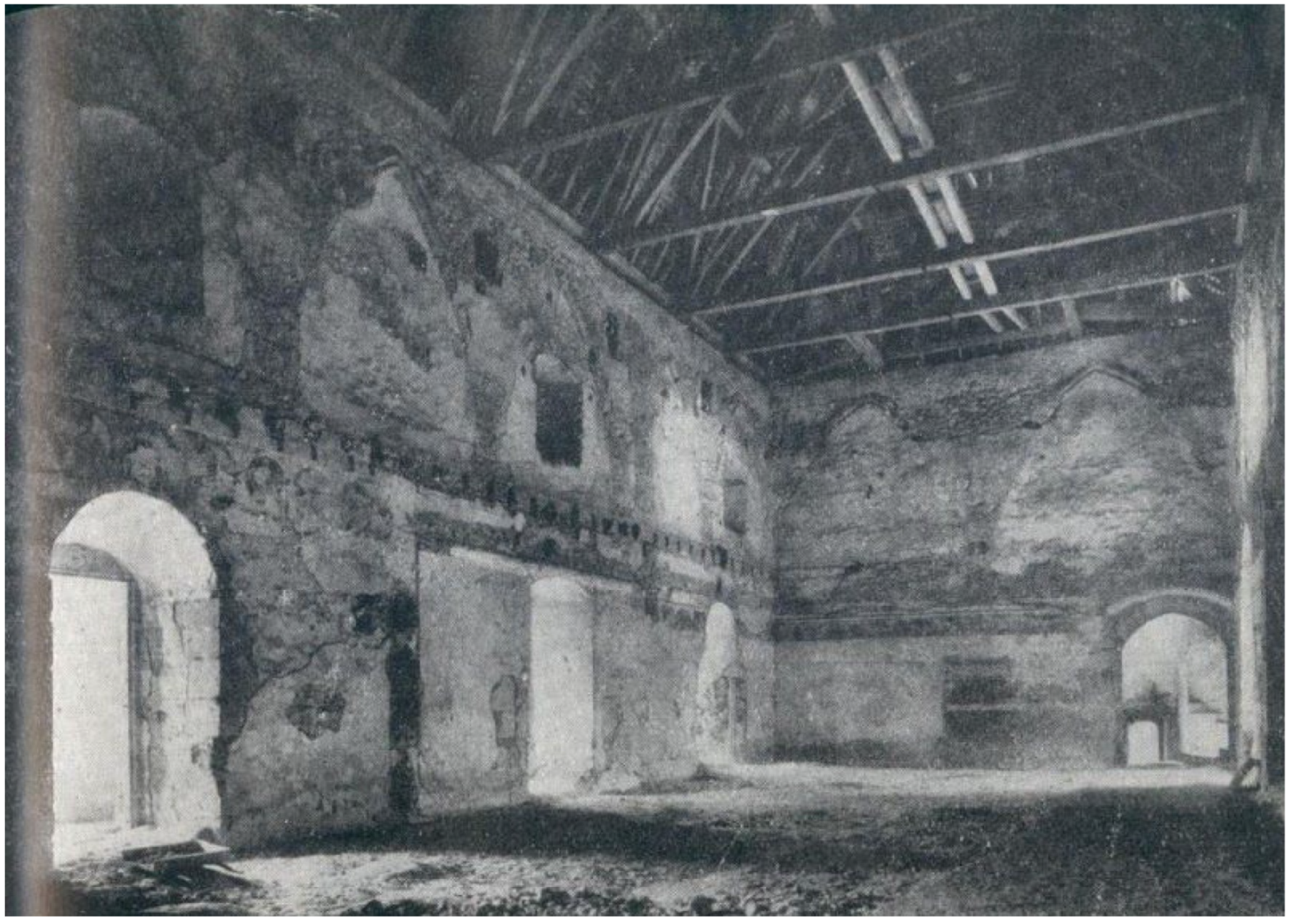
2.4.6. Diet Hall and Knight’s Hall (Sala Dietei and Sala Cavalerilor)
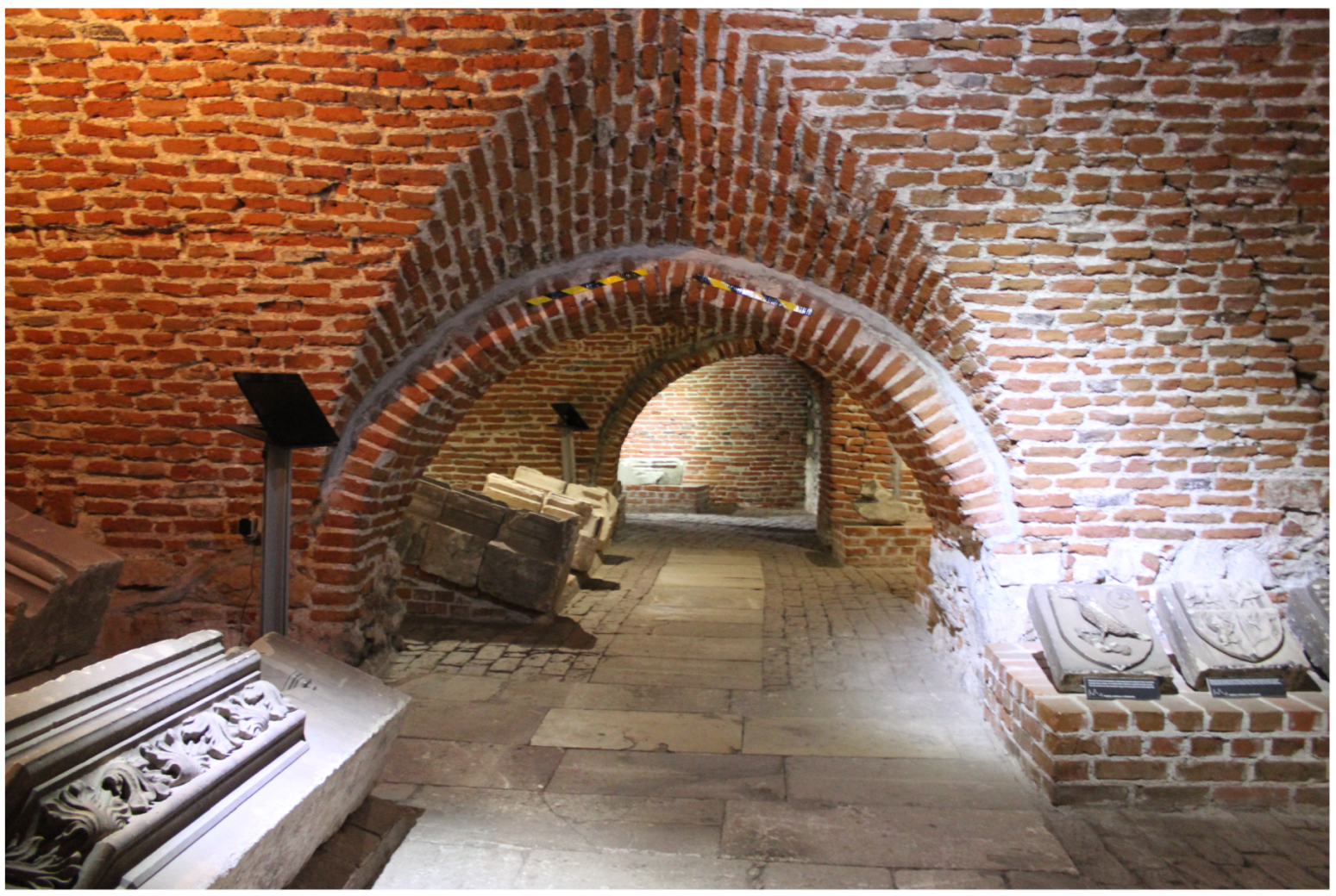
2.4.7. Lapidarium of the Corvin Museum and Gallery
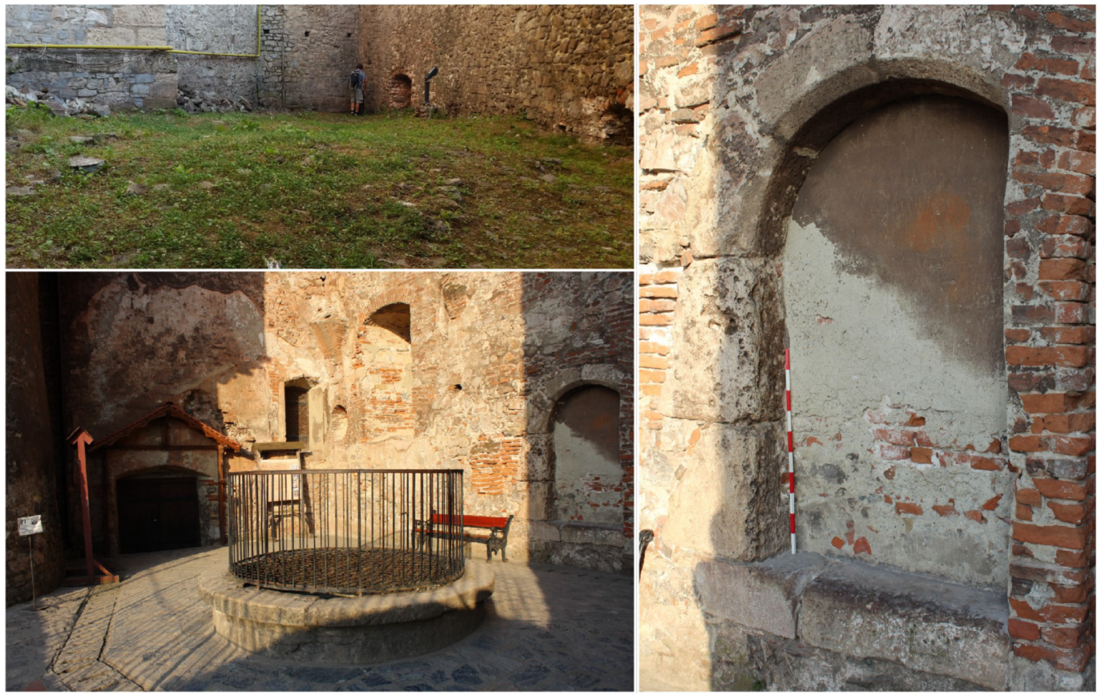
2.4.8. Northeast Sector
3. Results
3.1. Noble’s Man Kitchen
3.2. White Tower and Entrance Hall
3.3. Courtyard
3.4. Chapel
3.5. Neboisa Tower and Gallery
3.6. Diet Hall and Knight’s Hall
3.7. Lapidarium of the Corvin Museum and Gallery
3.8. Northeast Sector
3.8.1. Well Courtyard
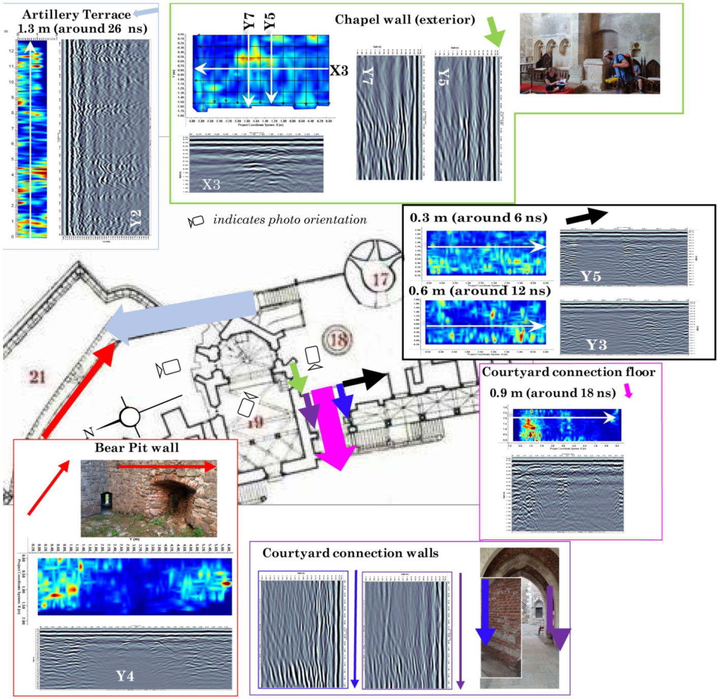
3.8.2. Bear Pit
3.8.3. Selected Walls
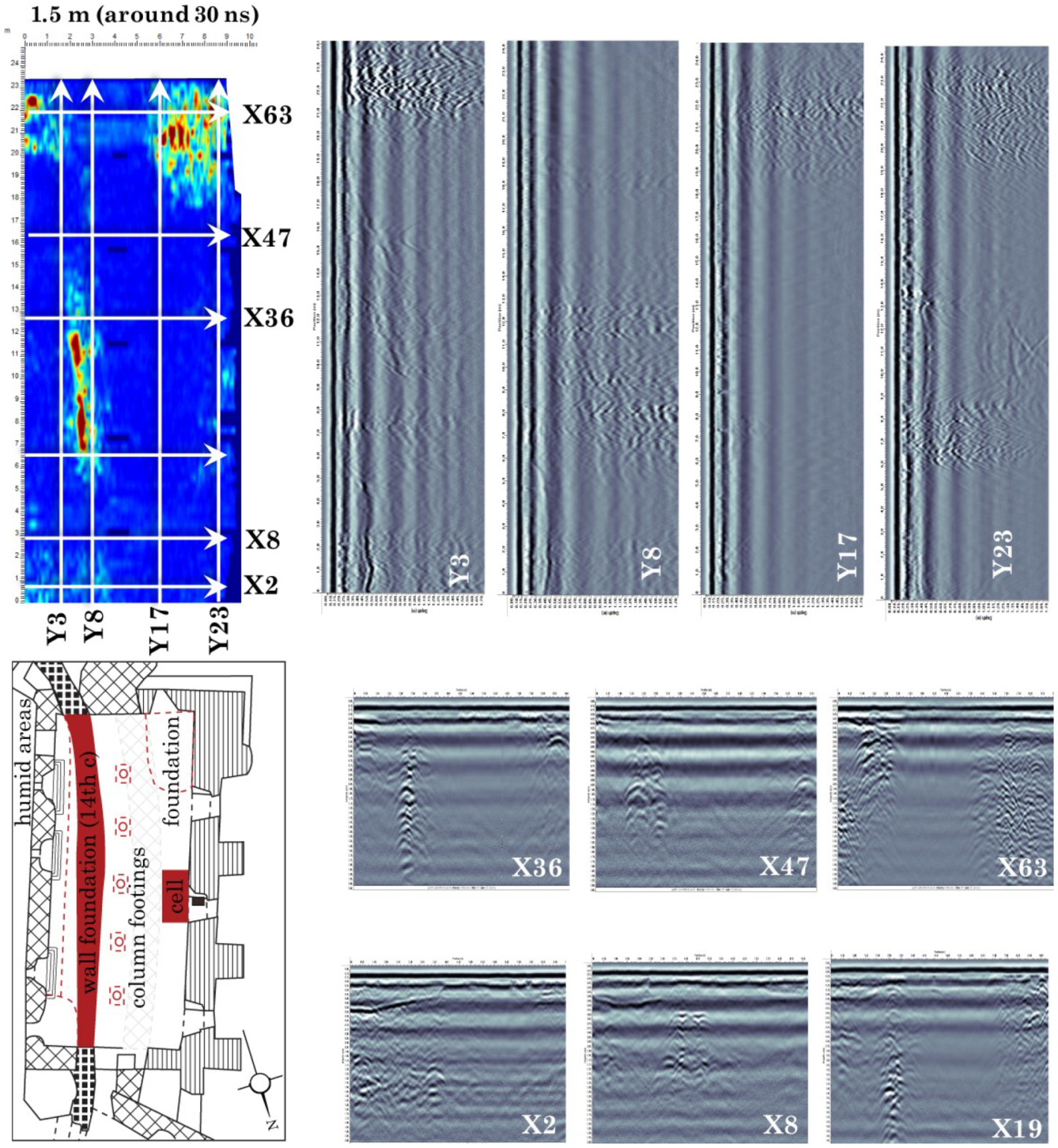
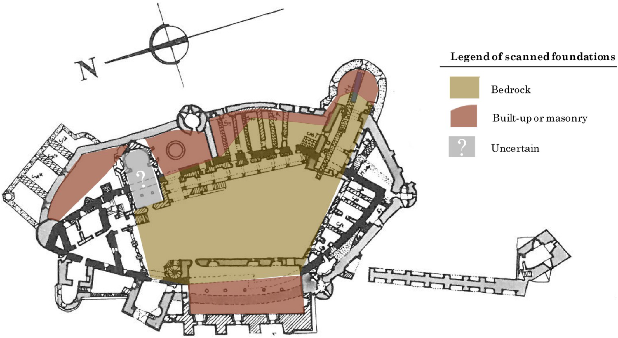
3.9. Foundations
4. Discussion
5. Conclusions
Author Contributions
Funding
Acknowledgments
Conflicts of Interest
References
- Velescu, O. Castelul de la Hunedoara; Editura Meridiane: Monumentele Patriei Noastre: Bucuresti, Romania, 1961. [Google Scholar]
- Bogdan, A. Contributii arheologice la cunoasterea evolutiei castelului corvinestilor de la hunedoara. Bul. Monum. Istor. 1970, 2, 18–25. [Google Scholar]
- Roman, C.C.; Tincu, S. Observations regarding the ecclesiastical complex from Hunedoara—The Corvin’s Castle. Sargetia Acata Musei Devensis 2012, 3, 243–258. [Google Scholar]
- Schilling, R. Historical conclusions about the archaeological excavations at the medieval castle of Hunedoara. Bul. Monum. Istor. 1970, 2, 55. [Google Scholar]
- Romulus, I. Romanian ironships of the 16th to 18th centuries. Steel Times 1999, 227, 392. [Google Scholar]
- Entz, G. Hunedoara Castle. In Oxford Art Online; Oxford University Press: Oxford, UK, 2003. [Google Scholar] [CrossRef]
- Vatasianu, V. Castelul Corvinilor din Hunedoara. Boabe de Grau 1933, 6, 420–431. [Google Scholar]
- Engle, M. The Collection of plans of the department of history of art. In Academic Showcases: The collections at the University of Vienna; Feigl, C., Beuran, D., Eds.; Bohlau Verlag: Vienna, Austria, 2016; pp. 118–120. [Google Scholar]
- Buck, S.L. Shaker Painted Furniture: Provocative Insights into Shaker Paints and Painting Techniques. In Painted Wood: History and Conservation; Dorge, V., Howlett, F.C., Eds.; The Getty Conservation Institute: Williamsburg, VA, USA, 1994; p. 143. [Google Scholar]
- Ramos, L.F.; Miranda, T.; Mishra, M.; Fernandes, F.M.; Manning, E. A Bayesian approach for NDT data fusion: The Saint Torcato church case study. Eng. Struct. 2015, 84, 120–129. [Google Scholar] [CrossRef]
- Binda, L.; Saisi, A.; Tiraboschi, C. Investigation procedures for the diagnosis of historic masonries. Constr. Build. Mater. 2000, 14, 199–233. [Google Scholar] [CrossRef]
- Ranieri, G.; Godio, A.; Loddo, F.; Stocco, S.; Casas, A.; Capizzi, P.; Messina, P.; Orfila, M.; Cau, M.A.; Chávez, M.E. Geophysical prospection of the Roman city of Pollentia, Alcudia (Mallorca, Balearic Islands, Spain). J. Appl. Geophys. 2016, 134, 125–135. [Google Scholar] [CrossRef]
- Annan, A. Ground Penetrating Radar Principles, Procedures, and Applications; Sensors and Software Inc.: Mississauga, ON, Canada, 2003; p. 285. [Google Scholar]
- Goodman, D.; Piro, S. GPR Remote Sensing in Archaeology; Springer: Berlin/Heidelberg, Germany, 2013. [Google Scholar]
- Conyers, L.B.; Goodman, D. Ground Penetrating Radar: An Introduction for Archaeologists; AltaMira: Walnut Creek, CA, USA, 1997; p. 232. [Google Scholar]
- Jol, H.M. (Ed.) Ground Penetrating Radar Theory and Applications; Elsevier Science: Amsterdam, The Netherlands, 2009; p. 544. [Google Scholar]
- Damiata, B.N.; Steinberg, J.M.; Bolender, D.J.; Zoëga, G.; Schoenfelder, J.W. Subsurface imaging a Viking-Age churchyard using GPR with TDR: Direct comparison to the archaeological record from an excavated site in northern Iceland. J. Archaeol. Sci. Rep. 2017, 12, 244–256. [Google Scholar] [CrossRef]
- Castellaro, S.; Imposa, S.; Barone, F.; Chiavetta, F.; Gresta, S.; Mulargia, F. Georadar and passive seismic survey in the Roman Amphitheatre of Catania (Sicily). J. Cult. Heritage 2008, 9, 357–366. [Google Scholar] [CrossRef]
- Perez Gracia, V.; Canas, J.A.; Pujades, l.G.; Clapes, J.; Caselles, O.; Garcia, F.; Osorio, R. GPR survey to confirm the location of ancient structures under the Valencian Cathedral (Spain). J. Appl. Geophys. 2000, 43, 167–174. [Google Scholar] [CrossRef]
- Pérez-Gracia, V.; Caselles, J.O.; Clapés, J.; Martinez, G.; Osorio, R. Non-destructive anlaysis in cultural heritage buildings: Evaluating the Mallorca cathedral supporting structures. NDT E Int. 2013, 59. [Google Scholar] [CrossRef]
- Ferrara, C.; Barone, P.M. Detecting moisture damage in archaeology and cultural heritage sites using the GPR technique: A brief introduction. Int. J. Archaeol. 2015, 3, 57–61. [Google Scholar] [CrossRef]
- Pincus, J.A.; De Smet, T.S.; Tepper, Y.; Adams, M.J. Ground-penetrating radar and electromagnetic archaeogeophysical investigations at the Roman legionary Camp at Legio, Israel. Archaeol. Prospect. 2013, 20, 175–188. [Google Scholar] [CrossRef]
- Conyers, L.B. Ground-penetrating radar mapping using multiple processing and interpretation methods. Remote Sens. 2016, 8, 562. [Google Scholar] [CrossRef]
- Ercoli, M.; Brigante, R.; Radicioni, F.; Pauselli, C.; Mazzocca, M.; Centi, G.; Stoppini, A. Inside the polygonal walls of Amelia (Central Italy): A multidisciplinary data integration, encompassing geodetic monitoring and geophysical prospections. J. Appl. Geophys. 2016, 127, 31–44. [Google Scholar] [CrossRef]
- Roman, C.C.; Tincu, S. Observatii pe marginea complexului ecleziastic de la Hunedoara—Castelul Corvinilor. Terra Sebus 2009, 1, 153–171. [Google Scholar]
- Pataki, I. Hunedoara Domain at the Beginning of the 16th Century: Study and Documents; Publishing House of the Academy of the Socialist Republic of Romania: Bucharest, Romania, 1973; Volume 39. [Google Scholar]
- Ion, R.M.; Iancu, L.; Carutiu, D.T.; Schroder, V.; Tincu, S.; Roman, C.; Ion, N.; Bucurica, I.A.; Teodorescu, S.; Dulama, I.D.; et al. Traditional building materials and modern restoration products identified at the painted Matia-fresco Loggia, Corvins’ Castle, Romania. In Proceedings of the Geophysical Research Abstracts: EGU General Assembly 2018, Vienna, Austria, 8–13 April 2018; EGU, Ed.; Volume 20, p. 5198. [Google Scholar]
- Ion, R.; Iancu, L.; Grigorescu, R.; Carutiu-Turcanu, D.; Tincu, S.; Ion, N.; Bucurica, I.; Teodorescu, S.; Dulama, I.; Stirbescu, R.; et al. Arhaeometric Concepts and Methods of Intervention on Historical Monument Buildings. The Case of the Corvins’ Castle. In IOP Conference Series: Materials Science and Engineering; IOP Publishing Ltd.: Bristol, UK, 2018; Volume 374. [Google Scholar] [CrossRef]
- Foldvary, G.Z. Geology of the Carpathian Region; World Scientific: Hackensack, NJ, USA, 1988. [Google Scholar]
- Morris, I.M.; Cleary, J.; Keppeler, J.G.; Gonciar, A.; Glisic, B. Confirming archaeological excavation results with ground penetrating radar: The main courtyard of Corvin Castle. In Proceedings of the AGU Fall Meeting, Washington, DC, USA, 10–14 December 2018. [Google Scholar]
- Roman, C.C.; Diaconescu, D.; Tiplic, M. Archaeological excavations at Hunedoara—The Corvins’ Castle—The sacristy of the chapel. In Studii de Istorie Veche si Arheologie: Bibliotheca Archaeologica et Historica Corvinensis—IV; Matos, C., Ed.; Editura Mereamia Napocae: Hunedoara, Romania, 2004. [Google Scholar]
- Filitti, G. Călători străini despre Ţările Române în secolul al XIX-lea; Number 2; Editura Academiei Române: Bucurest, Romania, 2005. [Google Scholar]
- Gonciar, A.; Roman, C.C. (Hunedoara, Romania). Personal Communication, 2017.
- Doehne, E.; Price, C.A. Stone Conservation: An Overview of Current Research, 2nd ed.; Getty Conservation Institute: Los Angeles, CA, USA, 2011; Volume 2, p. 164. [Google Scholar] [CrossRef]
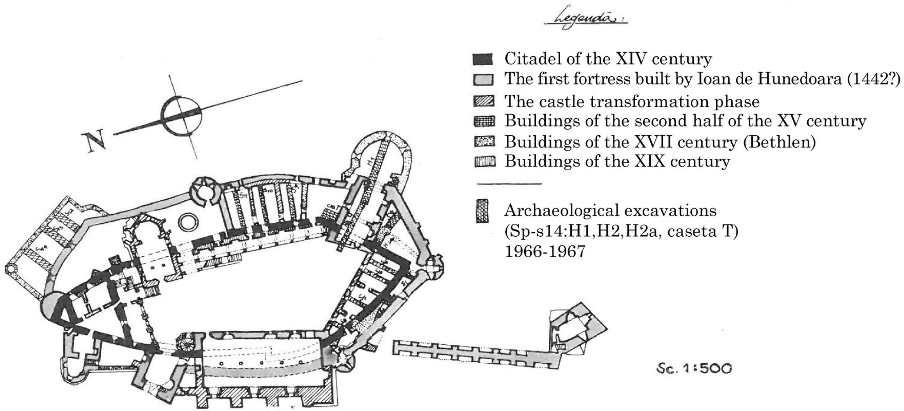
| 1. | Though Möller initially dated the first fortress to the late 13th century based on the composition of the mortar, historians throughout the 20th century generally agree that the fortress was more likely built sometime in the mid- to late-14th century. Roland Schilling makes a compelling argument for the first documentation of the fortress in the year AD 1364 as noted at the end of Bogdan’s German summary [2]. |
| 2. | Bogdan [2] elaborates that a campaign from 1966 to 1969 carried out “by the Historical Monuments Directorate of C.S.C.A. (Chief Project Officer E. Chefneux)” engaged in several restoration projects involving the Bethlen wing, the Zolyomi (South) wing, Diet Hall, the Matthaias Corvin wing and the Bethlen terrace. |
| 3. | The data is available by request from the authors (Andre Gonciar or Isabel Morris). |
| 4. | All three of these sources were translated from their original Romanian. The authors apologize if any information was lost or mistaken during translation. |
| 5. | Including, for example, Valentin Török reportedly beheading his adulterous wife Barbara in the courtyard in 1557 [1]. |
| 6. | The cell is incorrectly rumored to have briefly imprisoned Vlad the Impaler, but there is no evidence for this. |
| 7. | The well in the courtyard is sometimes called the “Turkish Well” because it was dug by Turkish prisoners during the 15th century. According to legend, the prisoners were promised their freedom in exchange for reaching water, but perhaps never freed upon completion of the well [1]. |
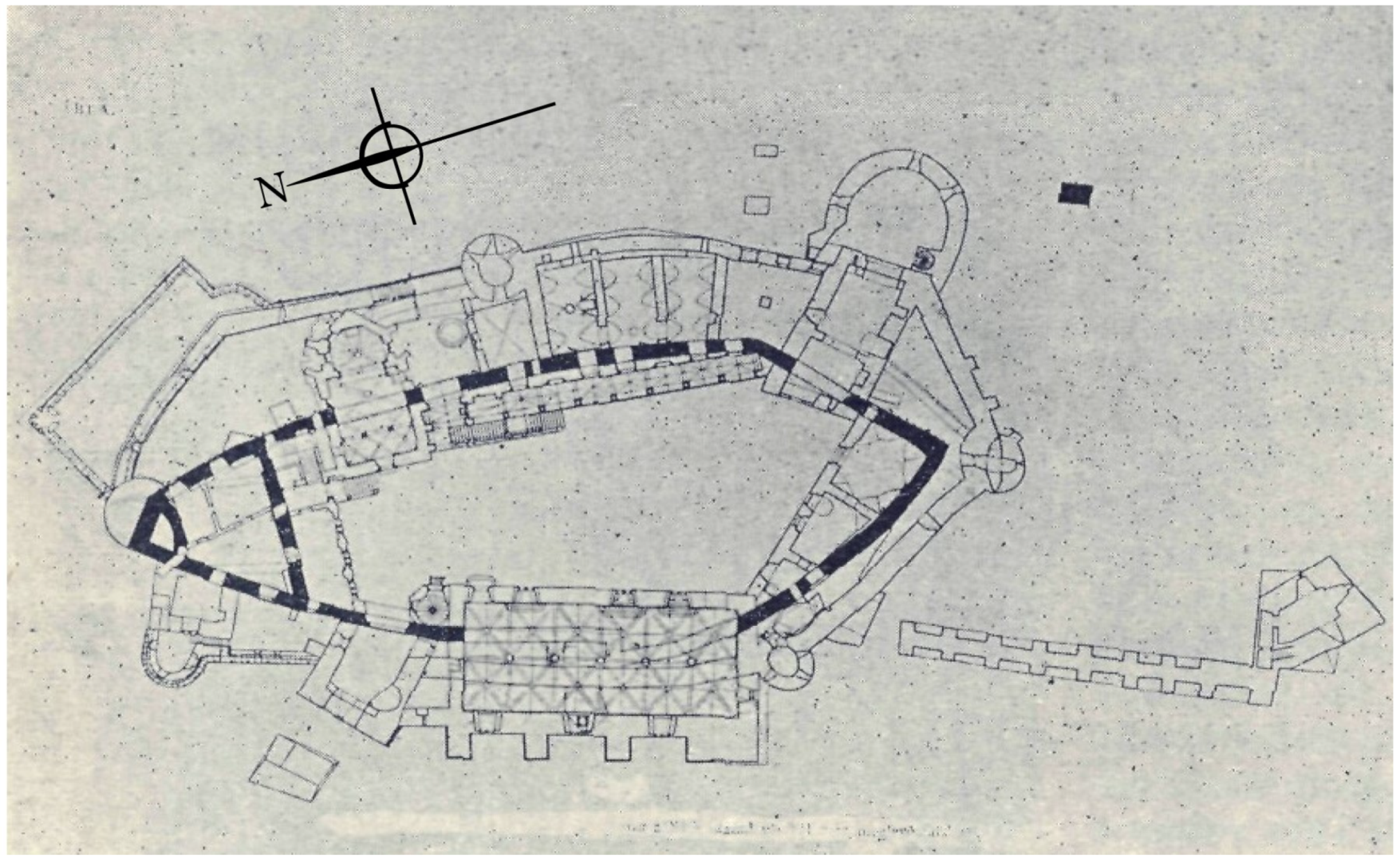
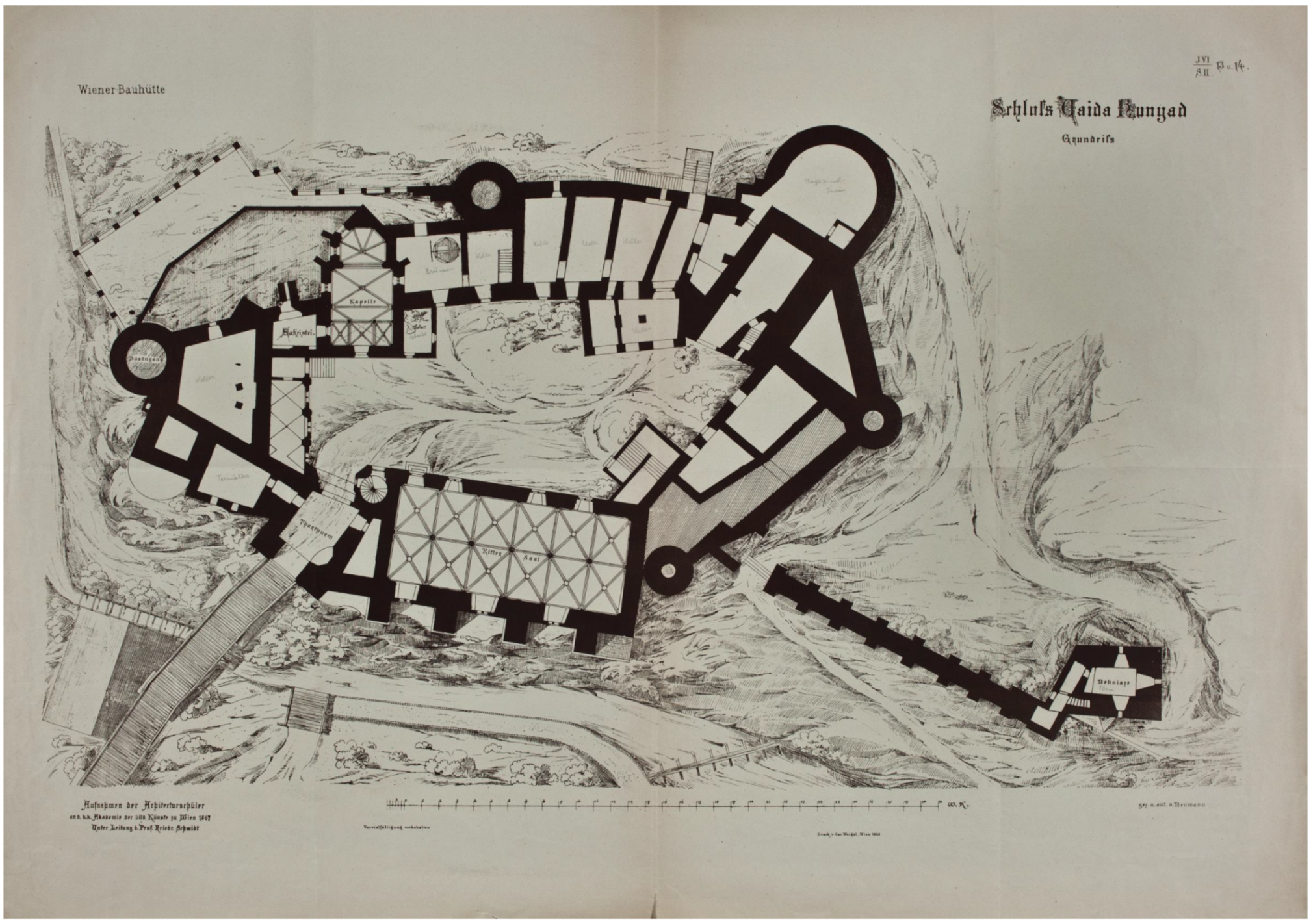
| 8. | Möller’s plans are based on his excavation and Aranyi’s drawings, and since his publication in the early 20th century historians have pondered the possibility of a tower structure in the NE corner of the original fortress not reflected in Möller’s plans. Historical documents and published stratigraphy neither confirm nor deny existence of this 14th century tower structure in the NE of Corvin’s Castle. |


© 2019 by the authors. Licensee MDPI, Basel, Switzerland. This article is an open access article distributed under the terms and conditions of the Creative Commons Attribution (CC BY) license (http://creativecommons.org/licenses/by/4.0/).
Share and Cite
Morris, I.; Cleary, J.; Gonciar, A.; Glisic, B. Ground Penetrating Radar Investigation of Corvin Castle (Castelul Corvinilor), Hunedoara, Romania. Heritage 2019, 2, 1316-1349. https://doi.org/10.3390/heritage2020085
Morris I, Cleary J, Gonciar A, Glisic B. Ground Penetrating Radar Investigation of Corvin Castle (Castelul Corvinilor), Hunedoara, Romania. Heritage. 2019; 2(2):1316-1349. https://doi.org/10.3390/heritage2020085
Chicago/Turabian StyleMorris, Isabel, Julia Cleary, Andre Gonciar, and Branko Glisic. 2019. "Ground Penetrating Radar Investigation of Corvin Castle (Castelul Corvinilor), Hunedoara, Romania" Heritage 2, no. 2: 1316-1349. https://doi.org/10.3390/heritage2020085
APA StyleMorris, I., Cleary, J., Gonciar, A., & Glisic, B. (2019). Ground Penetrating Radar Investigation of Corvin Castle (Castelul Corvinilor), Hunedoara, Romania. Heritage, 2(2), 1316-1349. https://doi.org/10.3390/heritage2020085