Abstract
Using the method of moments, we analyze three array antennas for low cross-polarized radiation. Each antenna comprises two dual-loop elements connected to a feedline horizontal to the ground plane. First, a feedline end is excited with an unbalanced source as a reference antenna. Next, the feedline center is excited with a balanced source, after the transformation of a decoupling array configuration. It is found that the antenna exhibits a cross-polarized radiation lower by 12 dB than the reference antenna. Last, the decoupling antenna is modified to have an unbalanced source without a complicated balun circuit design. It is pointed out that the modified antenna is an array of four loop elements, sequentially rotated by 90º.
1. Introduction
A circularly polarized (CP) antenna has unique characteristics, such as reduced polarization mismatching and multipath interference [1,2]. These characteristics have led to many applications in modern communication systems [3]. This paper concerns a CP antenna array [4,5,6,7,8,9] composed of dual-wire elements.
A dual-wire element above the ground plane has been investigated for CP radiation [10,11,12,13]. The antenna is characterized by a simple feed system, where two elements are excited with a single feed. Recently, a novel antenna using a resonant loop element with quasi-two sources [14] has been proposed to exhibit a wider CP wave bandwidth than an antenna using a non-resonant element [15].
This study is a continuation of the previous one [14] and presents new findings regarding a dual-loop antenna with quasi-two sources. We apply the dual loop in an array antenna for the first time. The array is composed of two dual-loop elements, connected to a feedline horizontal to the ground plane. The radiation characteristics are evaluated using the method of moments (MoM) [16].
Special attention is paid to a reduction in cross-polarized radiation. Three arrays are investigated: the reference, present, and modified antennas. The reference antenna has a horizontal feedline F–T, whose end F is excited with an unbalanced source (see Figure 1). In contrast, the present antenna’s feedline is excited at the center C with a balanced source (see Figure 2) after the transformation into a decoupling configuration to reduce cross-polarized radiation [17]. The modified antenna is excited at the feedline end F with an unbalanced source (see Figure 3) to simplify the feed system without a complicated balun-circuit design.
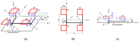
Figure 1.
Reference antenna with a horizontal feedline F–T, excited at one end F via a vertical wire F–F′. (a) Perspective view. (b) Top view. (c) Side view.
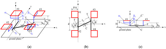
Figure 2.
Present antenna with a horizontal feedline F–T excited at the center C. (a) Perspective view. (b) Top view. (c) Side view.
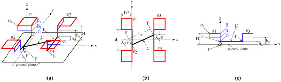
Figure 3.
Modified antenna with a horizontal feedline F–T excited at one end F via a vertical wire F–F′. (a) Perspective view. (b) Top view. (c) Side view.
The contribution of this study lies in replacing a balanced source required for a decoupling array antenna with an unbalanced source. The replacement is performed by shifting the excitation point from the center, along the horizontal feedline, by a quarter wavelength. Furthermore, a technical novelty is in a new observation: the modified antenna is an array of four single-loop elements, sequentially rotated by 90º. In other words, a conventional sequential rotation array antenna, with four single-loop elements, shown in Figure 3, has a quasi-decoupling array configuration, with two dual-loop elements (an authentic-decoupling array configuration is shown in Figure 2, where the array has a balanced source at the array center C). This new observation aids the understanding of decoupling and sequential rotation array configurations, serving as the groundwork for new ideas in antenna design in future work.
In this paper, we first present the radiation characteristics of the reference antenna. Next, we investigate the present antenna for CP radiation, paying attention to cross-polarized radiation. Lastly, the present antenna is modified for a simple feed system.
2. Reference Antenna
Figure 1 shows the configuration and coordinate system of the reference antenna. Two dual-loop elements are arrayed in the x-axis direction, with a distance of Lf and located at height H above the ground plane. Each dual-loop element comprises two square loops of perimeter P with a distance of d.
For CP radiation, each loop has adjacent corners αn and βn (n = 1, 2, 3, and 4) connected to a branched feedline αn/βn–Bn–γn vertical to the ground plane [14], as shown in Figure 1a,c. The branch point Bn and bottom end γn are at heights of hB and hL above the ground plane, respectively.
In each dual-loop element, the bottom end γm (m = 1 and 3) of the vertical, branched feedline is connected to another end γm+1 by a combining line γm–γm+1 in the y-axis direction, as shown in Figure 1a. Points F and T of the combining lines are connected by a horizontal feedline F-T in the x-axis direction, whose end F is excited by a coaxial line through a vertical wire F–F′ of length hL.
For wideband CP radiation, each dual-loop element has a sequential rotation array configuration [13,18]: one loop of #m is rotated by 90° and excited with a phase difference of 90° for the other loop of #m + 1. The excitation phase difference is made by an excitation point shift of λ0/8 along the combining line γm–γm+1 from the center, as shown in Figure 1b, where λ0 is the free-space wavelength at a test frequency f0. The antenna is made of wires with a radius ρ [13,14].
We analyze the antenna using our coded software based on the MoM [16]. The ground plane is assumed to have an infinite extent, and image theory is used in the analysis. The antenna is designed to radiate a CP wave in the direction normal to the antenna plane, in the z-axis direction. The loop parameters (P, hB) are selected for a horizontal feedline length of Lf = 1λ0. The other configuration parameters are fixed throughout the paper at the same values as those in [13,14] to facilitate the comparison: (d, H, hL, ρ) = (λ0/2, λ0/4, λ0/50, λ0/200).
Figure 4 shows the simulated radiation patterns for (P, hB) = (0.88λ0, 0.08λ0). The radiation is decomposed into right (ER) and left-hand (EL) CP wave components, which are shown with dotted and solid lines, respectively. The antenna radiates a left-hand CP beam in the z-axis direction. The half-power beam widths (HPBWs) are 27° and 36° in the ϕ = 0° and 90° planes, respectively. The gain is 12.3 dBi.
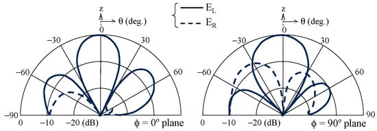
Figure 4.
Simulated radiation patterns of a reference antenna at f0.
It is observed in Figure 4 that the cross-polarized radiation ER is appreciable in the ϕ = 90° plane. The maximum ER level is −7.0 dB at θ = −41°. This cross-polarized radiation is reduced using a decoupling array configuration in the next section.
3. Present Antenna
The antenna configuration is shown in Figure 2. The decoupling array described in [17] has a symmetrical configuration concerning the array center and is excited at the center with the same amplitudes and a phase difference of 180°. This is accomplished in the present antenna as follows.
- Points T and F of the combining lines γm–γm+1 are symmetrical with respect to the center C of the horizontal feedline T–F, and the center is excited with a balanced source (emphasized with + and – in Figure 2);
- Loops #3 and #4 are rotated by 90° around their vertical lines β3–γ3 and β4–γ4, respectively, for the two dual-loop elements to become symmetrical concerning the configuration center C′, at height H, above the horizontal line center C, as shown in Figure 2c. Note that the horizontal feedline has a length of Lf, as shown in Figure 2b.
Figure 5 shows the simulated radiation patterns for (P, hB) = (0.92λ0, 0.09λ0) with Lf = λ0/2. The cross-polarized radiation ER shown with a dotted line in the ϕ = 90° plane is found to be reduced, compared to that of the reference antenna (see Figure 4). A reference antenna’s ER level of −7.0 dB, in the direction of (ϕ, θ) = (90°, −41°), is reduced by 11.9 dB compared to the present antenna in the same direction. It is also found that the maximum cross-polarized radiation is −12.8 dB at θ = ±90° in the ϕ = 0° plane. The HPBWs are 38°and 36° in the ϕ = 0° and 90° planes, respectively. The gain is 12.2 dBi.
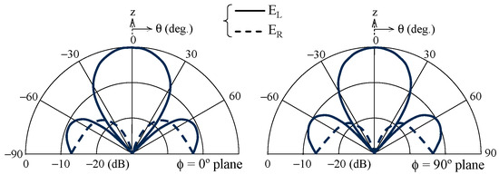
Figure 5.
Simulated radiation patterns of the present antenna at f0.
The simulated gain and axial ratio versus frequency are presented with solid lines in Figure 6. The gain has a peak value of 12.8 dBi, and drops from the peak by 3 dB at frequencies of 0.86f0 and 1.38f0, corresponding to a bandwidth of 46%. In this bandwidth, the axial ratio is less than 3 dB. For comparison, the results of the reference antenna are shown with dotted lines. The 3 dB gain drop bandwidth is 30%, where the axial ratio is less than 3 dB.
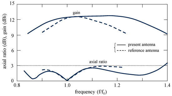
Figure 6.
Simulated frequency responses of axial ratio and gain of present and reference antennas.
4. Modified Antenna
Up to this point, we have discussed the reference and present antennas to reduce cross-polarized radiation. The present antenna is excited with a balanced source, which involves a complicated balun-circuit design for a coaxial line feed. In this section, we modify the present antenna so that the antenna can be excited with an unbalanced source.
Figure 3 shows the modified antenna. The excitation point C in the previous section is shifted along the horizontal line F–T by λ0/4 to the end F, at which the modified antenna is excited by a coaxial line via a vertical wire F–F′. This is the only difference between the antennas in the present and previous sections. We select the loop parameters (P, hB) for CP radiation, holding the other configuration parameters at the same values as those in the previous section.
The solid and dotted lines in Figure 7 show the simulated radiation patterns for (P, hB) = (0.91λ0, 0.08λ0). It is found that the antenna radiates a CP beam similar to that of the antenna in the previous section (see Figure 5). The maximum cross-polarized radiation is −12.0 dB at θ = −90° in the ϕ = 90° planes. The HPBWs are 38° and 36° in the ϕ = 0° and 90° planes, respectively. The gain is 12.5 dBi.
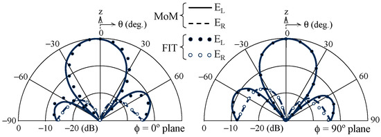
Figure 7.
Simulated radiation patterns of the modified antenna at f0.
The simulated gain and axial ratio versus frequency are shown with solid lines in the lower part of Figure 8. It is found that the 3 dB gain drop bandwidth is 39%, where the axial ratio is less than 3 dB. The reference antenna’s results are again presented with dotted lines. The modified antenna has a wider 3 dB gain drop bandwidth than the reference antenna (30%). Further calculations reveal that the modified antenna has a 3 dB axial ratio bandwidth of 57%, which is almost the same as that (54%) of the reference antenna.
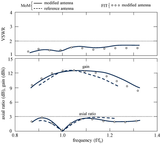
Figure 8.
Simulated frequency responses of the axial ratio, gain, and VSWR of the modified antenna.
The solid line in the upper part of Figure 8 shows the simulated frequency response of the VSWR of the modified antenna. The VSWR is evaluated for a 50 Ω coaxial line. It is observed that the antenna has a VSWR of less than 2 in the 3 dB gain drop bandwidth.
When comparing the 3 dB axial ratio bandwidths of the modified (57%) and reference (54%) antennas, a question arises. Why are the bandwidths of the modified and reference antennas almost the same? The answer is that the modified antenna is also regarded as a sequential rotation array composed of four loops, i.e.,
- Referring to the loops shown in Figure 3a, we see that loops #2, #1, #3, and #4, are sequentially rotated 90° clockwise around their vertical lines βn–γn. The clockwise rotation makes the phase of partial radiation from each loop progress by 90°, since the antenna radiates a left-hand (EL) CP beam, as shown in Figure 7;
- Referring to a feed network composed of the horizontal feedline F–T of length Lf and combining lines γm–γm+1 of length d, shown in Figure 3b, we recognize that the excitation phases of loops #2, #1, #3, and #4, in turn, are sequentially delayed by 90° (to compensate for a radiation phase progress of 90°), since the line lengths are Lf = d = λ0/2, leading to a sequential increase of λ0/4 in the path length to each loop from the excitation point F.
Thus far, the simulated results have been discussed using the MoM. To verify the results, we reproduce them using a finite integration technique (FIT), i.e., commercial software called CST Studio Suite [19]. The results are shown with small circles and dots in Figure 7 and Figure 8. The FIT results agree with the MoM results.
Finally, we compare our results with those of similar studies. The comparisons are summarized in Table 1. It is emphasized that the modified antenna has the widest CP wave bandwidth. Note that all the studies deal with an array antenna composed of four resonant elements, sequentially rotated by 90°.

Table 1.
Comparison with similar studies.
As additional data, photographs of an antenna fabricated at f0 = 3 GHz are shown in Figure 9. In addition, Figure 10b and Figure 11 show tentative experimental results using the fabricated antenna. It is apparent that the experimental results are similar to the MoM results, which are identical to those in Figure 7 and Figure 8.
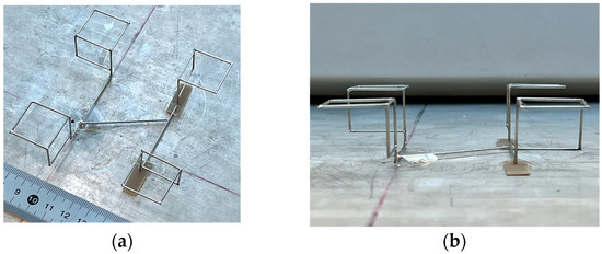
Figure 9.
Photographs of a prototype for a modified antenna. (a) Perspective view. (b) Side view.
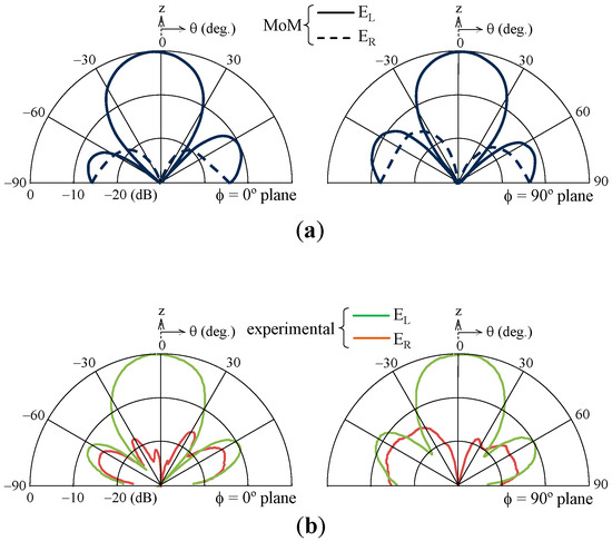
Figure 10.
Radiation patterns of a modified antenna at f0. (a) simulated results. (b) experimental results.
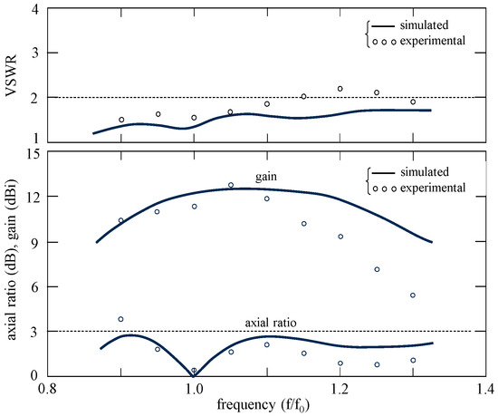
Figure 11.
Frequency responses of axial ratio, gain, and VSWR of a modified antenna.
The following questions may arise before the conclusion:
- (1)
- Which antenna is a proposed one that significantly improves previous research results?
- (2)
- The modified antenna has no improvement in antenna characteristics and provides worse measured results than the simulated ones.
- (3)
- What does the quasi-decoupling mean and in what way can it be quantified?
- (4)
- The decoupling used in the title and the abstract is not obvious.
- (5)
- Dimensions and implementation details are not provided. Therefore, we cannot verify the presented results.
- (6)
- What is the parasitic radiation of relatively long feedlines?
- (7)
- How is the radius of the wire selected to satisfy the impedance matching requirement?
The answers to the above questions are:
- (1)
- We proposed the modified (sequential rotation) antenna with the widest CP wave bandwidth in previous studies, as shown in Table 1. The present (decoupling) antenna plays a role in finding a new observation in decoupling and sequential rotation array configurations, as in the title. This study claims a new observation as well as a new antenna proposition.
- (2)
- We compare the modified antenna to the reference one since the present antenna has a balanced feed that requires a complicated balun-circuit design for a coaxial-line feed. In addition, the measured results are considered additional data in this study because we verify the MoM results using the FIT ones.
- (3)
- The quasi-decoupling means that it reduces cross-polarized radiation, like authentic decoupling, but without a balanced feed. A reduction in cross-polarized radiation is used to quantify the quasi-decoupling.
- (4)
- The decoupling is used for the following [17]: The cross-polarized radiation is coupled to co-polarized radiation. If the coupling is released (this is called decoupling), the cross-polarized radiation is reduced. The reduction is performed via a cancelation of the cross-polarized, partial radiation from each antenna configuration part, where the antenna comprises two configuration parts symmetrical to the antenna center.
- (5)
- The dimensions and implementation are summarized in Table 2. It is shown that we can design the three antennas by optimizing just two parameters (P, hB). This optimization makes it easy to verify the presented results.
Table 2. Antenna dimensions and implementation.
- (6)
- The parasitic radiation from the feedline is smaller than the loop one, since the feedline height above the ground plane needs to be as small as possible, hL = λ0/50, compared to the loop height of H = λ0/4, as shown in Table 2. This smaller parasitic radiation enables us to design the antennas using the loop parameters (P, hB).
- (7)
- For the impedance matching, we do not choose the wire radius ρ but the horizontal feedline height: hL = λ0/50, giving a characteristic impedance of Z0 = 125 Ω. This Z0 matches both the coaxial feed and loop elements.
5. Conclusions
We have designed two dual-loop antenna arrays, each having a feedline horizontal to the ground plane. One end of the feedline of the reference antenna was excited with an unbalanced source. In contrast, the feedline center of the present antenna was excited with a balanced source for low cross-polarization. It was revealed that the present antenna exhibited a lower cross-polarization level by 12 dB, compared to that of the reference antenna. Subsequently, we modified the present antenna by replacing the balanced source with an unbalanced one for a simple feed system. The modified antenna still exhibited a low cross-polarization, having a 3 dB gain drop bandwidth of 39%, where the axial ratio and VSWR were less than 3 dB and two, respectively. We pointed out that the modified antenna is a sequential rotation array composed of four single-loop elements; simultaneously, the antenna has a quasi-decoupling array configuration comprising two dual-loop elements.
Author Contributions
Conceptualization, K.H.; software, K.H.; validation, K.H.; investigation, K.N.; resources, K.H.; data curation, K.N.; writing—original draft preparation, K.H.; writing—review and editing, K.H.; visualization, K.H.; supervision, K.H. and H.N.; project administration, K.H. All authors have read and agreed to the published version of the manuscript.
Funding
This research received no external funding.
Institutional Review Board Statement
Not applicable.
Informed Consent Statement
Not applicable.
Data Availability Statement
Numerical and experimental data used to support the findings of this study are included in this article.
Acknowledgments
The authors would like to thank Blair Thomson for his invaluable assistance in preparing this paper.
Conflicts of Interest
The authors declare no conflicts of interest.
References
- Gao, S.; Luo, Q.; Zhu, F. Circularly Polarized Antennas; John Wiley & Sons, Ltd.: Chichester, UK, 2014. [Google Scholar]
- Ullah, U.; Ain, M.F.; Ahmad, Z.A. A review of wideband circularly polarized dielectric resonator antennas. China Commun. 2017, 14, 65–79. [Google Scholar] [CrossRef]
- Nadeem, I.; Alibakhshikenari, M.; Babaeian, F.; Althuwayb, A.A.; Virdee, B.S.; Azpilicueta, L.; Khan, S.; Huynen, I.; Falcone, F.; Denidni, T.A.; et al. A comprehensive survey on ‘circular polarized antennas’ for existing and emerging wireless communication technologies. J. Phys. D Appl. Phys. 2022, 55, 033002. [Google Scholar] [CrossRef]
- Zeng, W.; Wu, X.; Wu, F.; Zang, Y.; Jiang, Z.; Hong, W.; Luk, K. Broadband dual-CP multi-stage sequential rotation arrays with independent control of polarizations based on dual-CP magnetoelectric dipole elements. IEEE Trans. Antennas Propag. 2024, 4, 3017–3032. [Google Scholar] [CrossRef]
- Hester, D.; Han, S.; Adams, M. Design methodology for single-feed circularly polarized X-band antenna arrays for CubeSats using multilevel sequential rotation. IEEE J. Miniat. Air Space Syst. 2024, 5, 42–50. [Google Scholar] [CrossRef]
- PourMohammadi, P.; Fei, P.; Nasseri, H.; Zheng, Q.; Babarinde, O.; Volski, V.; Vandenbosh, A.; Denidni, T. A single-layer compact wideband circularly polarized patch array for 5G communications. IEEE Antennas Wirel. Propag. Lett. 2023, 22, 754–758. [Google Scholar] [CrossRef]
- Qi, Z.; Zhu, Y.; Li, X. Compact wideband circularly polarized patch antenna array using self-sequential rotation technology. IEEE Antennas Wirel. Propag. Lett. 2022, 21, 700–704. [Google Scholar] [CrossRef]
- Santosa, C.E.; Sumantyo, J.; Gao, S.; Ito, K. Broadband circularly polarized microstrip array antenna with curved-truncation and circle-slotted parasitic. IEEE Trans. Antennas Propag. 2021, 69, 5524–5533. [Google Scholar] [CrossRef]
- Sun, M.; Liu, N.; Zhu, L.; Fu, G. Wideband circularly polarized sequentially rotated microstrip antenna array with sequential-phase feeding network. J. Commun. Inf. Netw. 2020, 5, 350–357. [Google Scholar] [CrossRef]
- Zhang, Y.; Zhu, L. Printed dual spiral-loop wire antenna for broadband circular polarization. IEEE Trans. Antennas Propag. 2006, 54, 284–288. [Google Scholar] [CrossRef]
- Li, R.; DeJean, G.; Laskar, J.; Tenzeris, M.M. Investigation of circularly polarized loop antennas with a parasitic element for bandwidth enhancement. IEEE Trans. Antennas Propag. 2005, 53, 3930–3939. [Google Scholar]
- Sumi, M.; Hirasawa, K.; Shi, S. Two rectangular loops fed in series for broadband circular polarization and impedance matching. IEEE Trans. Antennas Propag. 2004, 52, 551–554. [Google Scholar] [CrossRef]
- Hirose, K.; Kikkawa, Y.; Nakano, H. Decoupling and sequential array antennas—Effects of coplanar feedline on radiation characteristics. IEEE Antennas Wirel. Propag. Lett. 2020, 19, 423–427. [Google Scholar] [CrossRef]
- Hirose, K.; Nishino, K.; Nakano, H. Dual-loop antennas with an expanded axial ratio bandwidth. Electron. Lett. 2023, 59, e12784. [Google Scholar] [CrossRef]
- Hirose, K.; Nakatsu, M.; Nakano, H. Dual-curl antennas for broadband circular polarisation. Electron. Lett. 2021, 57, 542–544. [Google Scholar] [CrossRef]
- Harrington, R.F. Fields Computation by Moment Methods; Macmillan: New York, NY, USA, 1968. [Google Scholar]
- Shelley, M.W.; Brain, D.J.; Roederer, A.; Markus, K. A novel high efficiency, dual polarised, flat plate array. In Proceedings of the Eighth International Conference on Antennas and Propagation, Edinburgh, UK, 30 March–2 April 1993. [Google Scholar]
- Nakano, H.; Matsumoto, S.; Ochiai, N. Improvement of the axial ratio for circularly polarized multi-arm antenna. In Proceedings of the Combined Conference of Four Institutions Related to Electrical Engineering, Japan, October 1975. [Google Scholar]
- CST Studio Suite. Available online: https://www.cst.com/applications/mwandrf (accessed on 25 December 2024).
Disclaimer/Publisher’s Note: The statements, opinions and data contained in all publications are solely those of the individual author(s) and contributor(s) and not of MDPI and/or the editor(s). MDPI and/or the editor(s) disclaim responsibility for any injury to people or property resulting from any ideas, methods, instructions or products referred to in the content. |
© 2025 by the authors. Licensee MDPI, Basel, Switzerland. This article is an open access article distributed under the terms and conditions of the Creative Commons Attribution (CC BY) license (https://creativecommons.org/licenses/by/4.0/).