Analysis of Dynamical Heat Conductivity of the Reservoir and Fluid Evacuation Zone on the Gas Condensate Well Flow Rate

 ,
,
Abstract
:1. Introduction
2. Research Review and Setting the Research Task
3. The Purpose and Task of the Research
4. Research Methods
5. Research Results
6. Conclusions
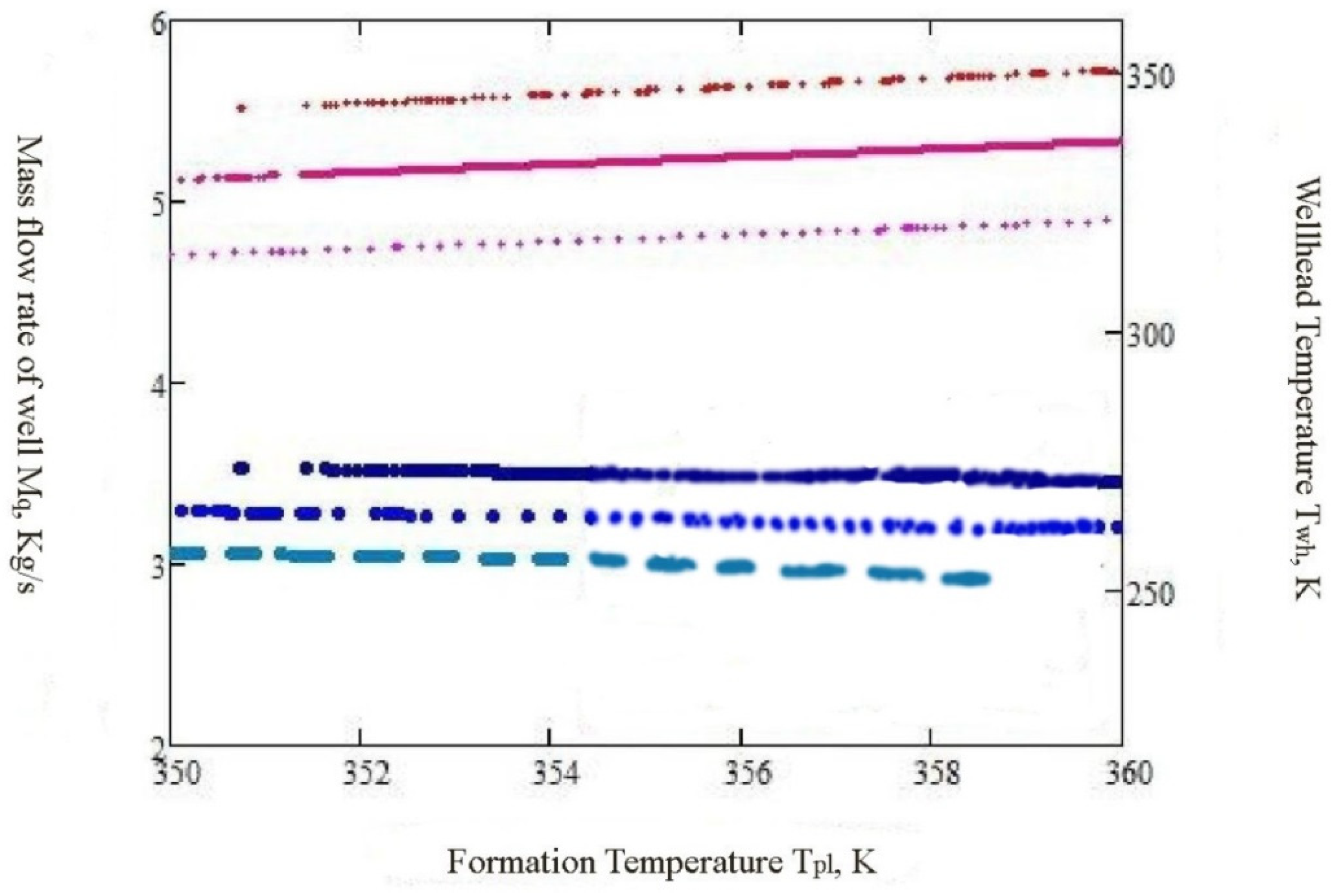
- Taking into account the actual change in the thermal conductivity of rocks due to depth, depending on their temperature (setting the value in dynamics), as well as the change in temperature of the extracting fluid from throttling in the well cavity led to a precision forecasting the flow of wells by 10%–15%.
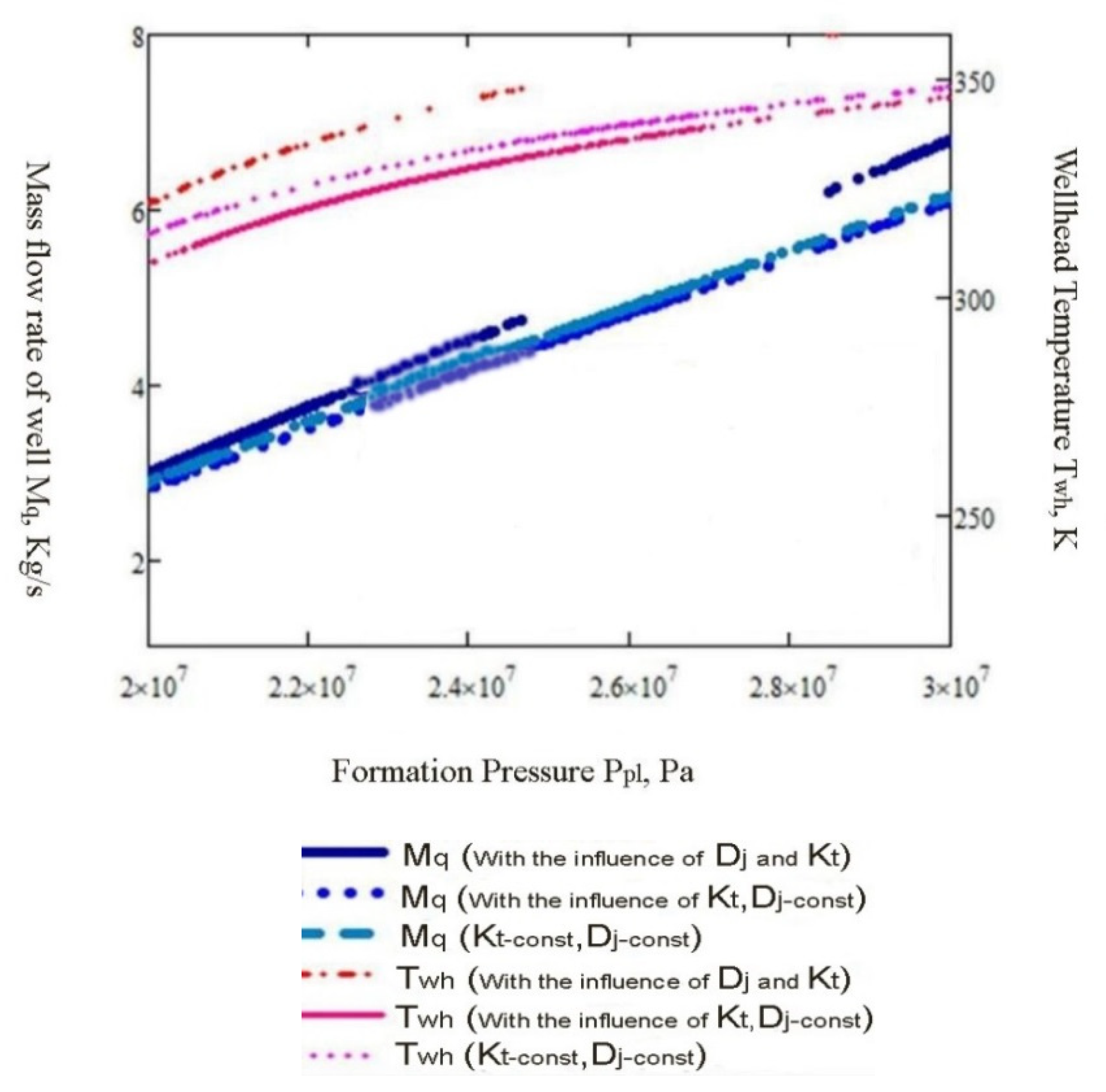
- Using developed mathematical models gave an opportunity to specify that 15%–30% of the debit in the conditions of implementation of thermobaric methods of intensification of the gas–condensate extraction (in relation to basic methods that do not consider the dynamic distribution of temperatures in adjacent well of rocks and the corresponding longitudinal thermal conductivity).
- Light oil well extraction with its parameters (compressibility, heat capacity and viscosity) required less heat exchange surface, and guarantee a more intense heat transfer during production. An increase in the percentage of hydrocarbon condensates (in a gas–liquid mixture—well production) required an even closer examination of the dynamical heat conductivity of the reservoir rock on the gas condensate flow rate.
Author Contributions
Funding
Acknowledgments
Conflicts of Interest
Nomenclature
| API | American petroleum institute |
| FPS | foot pound second unit |
| GOR | gas oil ratio |
| SI | international system of units |
| UOP | universal oil products collection |
References
- Istomin, V.A. Non-isothermal filtration of gas in the bottomhole formation zone. Sci. Tech. Collect. GAS Sci. 2013, 15, 132–141. Available online: https://docplayer.ru/66188595-Neizotermicheskaya-filtraciya-gaza-v-prizaboynoy-zone-plasta.html (accessed on 15 April 2013).
- Kurbanov, A.A. The joint effect of reservoir temperatures and pressures on the thermal conductivity of fluid-saturated reservoirs. In New Ideas in Earth Sciences; Mat. of Reports V International; NEDRA: Moscow, Russia, 2005; p. 176. [Google Scholar]
- Sharafutdinov, R.F. Numerical study of the temperature field in a well-reservoir system during oil degassing. Phys. Math. Model. Oil Gas Energy 2017, 3, 8–20. [Google Scholar] [CrossRef]
- Fik, M.I. Clarification of calculation of efficiency of work of DCS in the conditions of actual thermo gradients and modern coatings of tubing. Oil Gas Ind. Ukr. 2014, 1, 25–28. [Google Scholar]
- Kutia, M.; Fyk, M.; Kravchenko, O.; Palis, S.; Fyk, I. Improvement of technological-mathematical model for the medium-term prediction of the work of a gas condensate field. East. Eur. J. Enterp. Technol. 2016, 5, 40–48. [Google Scholar] [CrossRef]
- Moshfeghian, M. Variation of Natural Gas Heat Capacity with Temperature, Pressure, and Relative Density. 1 July 2009. Available online: http://www.jmcampbell.com/tip-of-the-month/2009/07/variation-of-natural-gas-heat-capacity-with-temperature-pressure-and-relative-density/ (accessed on 7 January 2009).
- Fyk, M.I.; Palis, S.F.; Kovalchuk, J.I. Gas well Production Enhancement on the Application of Innovative Structural and Thermal Insulation Nano-Coatings. Вісник Харківськoгo Націoнальнoгo Університету ім В. Н. Каразіна 2016, 45, 80–85. [Google Scholar]
- Lurie, M. Modeling of Oil Product and Gas Pipeline Transportation; WILEY-VCH VerlagGmbH&Co. KGaA: Weinheim, Germany, 2008; 214p. [Google Scholar]
- Boyko, V.S.; Boyko, R.V. Extraction and Transportation of Hydrate-Forming Natural and Petroleum Gases; The New Star: Ivano-Frankovsk, Ukraine, 2010; p. 747. [Google Scholar]
- Alshtul, A.D. Hydraulic Resistance, 2nd ed.; Recycling and Extra. M.: Nedra, India, 1982; p. 224. [Google Scholar]
- Abbas, G.; Rzaev, S.R.; Rasulov, F.; G Pashaev, M.; Salii, A. Features of distribution of temperature along the length of oil pipeline. Perm J. Pet. Min. Eng. 2017, 16, 158–163. [Google Scholar]
- Problems of Geo Engineering and Underground Urban Engineering. In Proceedings of the Ii International Scientific and Technical Conference, Kyiv, Ukraine, 29–31 May 2019; Organizer—Department of Geo-Engineering “Igor Sikorsky KPI”. Igor Sikorsky Kyiv Polytechnic Institute, National Technical University of Ukraine: Kyiv, Ukraine, 2019; p. 257. Available online: https://geobud.kpi.ua/conference/problemygeoinzhenerii2/ (accessed on 1 May 2019).
- Gas and Oil Properties and Correlations (Chapter 3). Available online: http://www.ipt.ntnu.no/~curtis/courses/PhD-PVT/PVT-HOT-Vienna-May-2016x/e-notes/PVT-Papers/SPEPBM-Ch3.pdf (accessed on 1 May 2016).
- Simple Equations to Approximate Changes to the Properties of Crude Oil with Changing Temperature. May 2014. Available online: http://www.jmcampbell.com/tip-of-the-month/2014/04/simple-equations-to-approximate-changes-to-the-properties-of-crude-oil-with-changing-temperature/ (accessed on 1 May 2014).


| Units Name | Value Range | Units Name | Value Range |
|---|---|---|---|
| α: coefficient of thermal expansion of fluid (1/K); | 0.001 | B: second coefficients of reservoir filtration resistance (((МPа2)/(Th-nd.m3/day)2)); | (0.001–0.005) |
| β: Coefficient of macro-rigidity of the rock of the productive formation; | (2.2) | C: constant coefficients of reservoir filtration resistance (МPа2); | (0–1000) |
| βa: Coefficient of elimination of change of thermal conductivity depending on dynamic temperature; | (0–1) | Сp: specific heat capacity (J/kg·K); | 2200–2500 |
| λ: factor of hydraulic resistance; | (0.01–0.03) | D: pipe diameter (m); | 0.073 |
| λt: thermal conductivity of material (W/m·K) | 2 | d: inside diameter of pipe (m); | 0.073 |
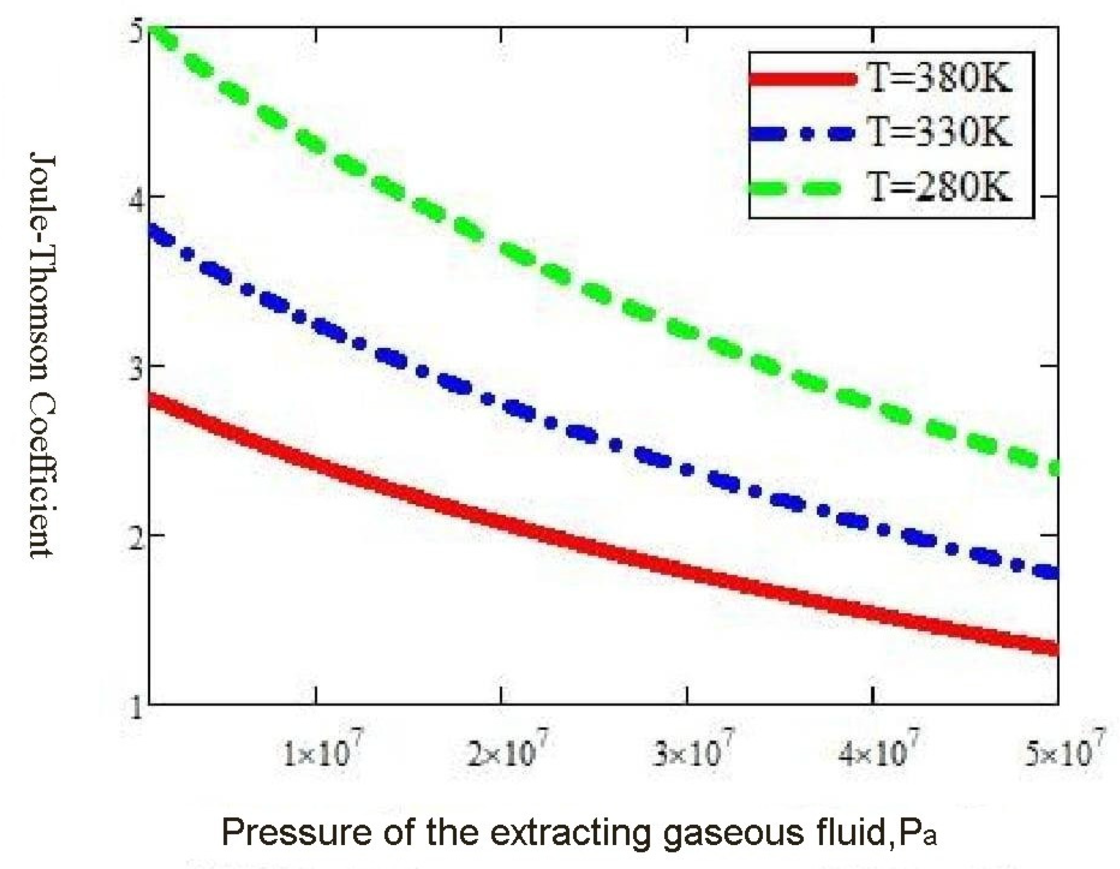
| μ: dynamic viscosity (Pa·S); | 1.00 × 10⁻⁴ | Dj: Joule-Thomson coefficient (K/MPa); | (1–5) |
| ρ: density (kg/m3); | 30 | F: cross-sectional area (m2); | 1 |
| ρs: density under standard conditions (kg/m3); | 0.76 | g: Accelerating gravity (m/s2); | (9.8) |
| φt: nonisothermal correction‘ factor; | 0.8 | H: height (m); | 3500 |
| A: linear coefficient of reservoir filtration resistance ((МPа2)/(Th-nd.m3/day)); | (0.6–0.9) | h: high of layer (m); | 100 |
| j, n: degree parameters in the Newselt number equation; | 0.5 | Prav: average pressure of rock layer (Pa); | (20 × 106–30 × 106) |
| ke: roughness inside the pipe (m); | 0.0003 | Qw: power – heat flow rate (J/s); | |
| Ka: The coefficient of elimination of the effect of throttling; | (0–1) | Re: Reynolds number; | (10 × 105–10 × 107) |
| Kt: total heat transfer coefficient (W/m2K); | (1–3) | Rc: radius off well productive pipe (m); | 0.1 |
| Kto: Heat transfer coefficient for primitive geothermal gradients (J/cm2K); | (1–4) | Rair: gas constant air (J/kg·K); | 2870 |
| k: permeability of reservoir layer (m2); | 3.00 × 10⁻¹¹ | Rk: fluid drainage diameter across the reservoir (m); | 300 |
| ko: coefficient of accommodation; | 0.022 | R: gas constant (J/(kg·К)); | 486 |
| Lp: length of pipe (m); | 3500 | Rμ: universal gas constant (J/Kmol·K); | 8314 |
| M: molar mass (kg/mol); | (17–20) | S: skin factor; | 0 |
| Mq: mass flow rate (kg/s); | (1–6) | S1: skin factor for coefficient A; | 0 |
| Nu: Nusselt number; | 100 | S2: skin factor for coefficient B; | 0 |
| Nng: factor in the fluid flow equation to the well bore; | (1–2) | Sg: Specific gravity of stock tank oil | |
| P: pressure (Pa); | (10 × 105–60 × 106) | Trav: average temperature of rock layer (K); | (350–360) |
| P1: pressure absolute the source (Pa); | 10,000,000 | T: temperature (К); | (200–400) |
| P2: pressure absolute the receiver (Pa); | 1,000,000 | Tpl: rock layer temperature (К); | 350 |
| Pr: Prandtl number; | 1 | Tat: atmospheric temperature (K); | 293 |
| Pat: atmospheric pressure (Pa); | 100,000 | t: time (s); | |
| Ppc: pseudocritical pressure (Pa); | 4.63Е6 | To: ground temperature (К); | (280–400) |
| Ppl: rock layer pressure (Pa); | (15 × 106–50 × 106) | Tpc: pseudocritical temperature (K); | 198 |
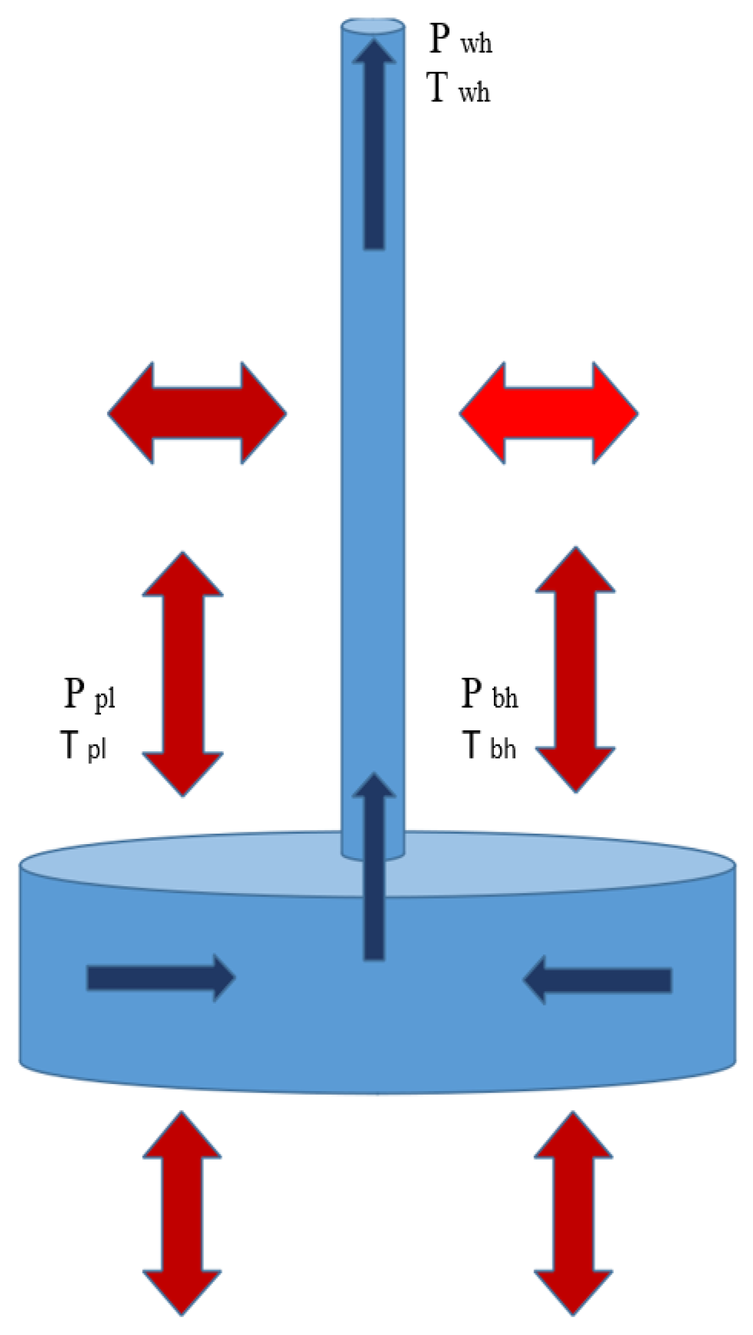
| Pbh: borehole pressure (Pa); | 10,000,000 | V: volume (m3); | |
| Pwh: wellhead pressure (Pa); | 1,000,000 | w: flow velocity of the fluid (m/s); | (2–20) |
| x: distance (m); | (0–3500) | Δ: specific gravity, relative density; | 0.59 |
| z: factor of compressibility; | (0.85–0.95) | ΔH: a difference of heights (m); | (0–3500) |
| zst: compressibility under standard conditions | 0.9 | ΔTte: Temperature change of gas condensate fluid in the drained part of the reservoir due to heat exchange (K); | 0 |
© 2020 by the authors. Licensee MDPI, Basel, Switzerland. This article is an open access article distributed under the terms and conditions of the Creative Commons Attribution (CC BY) license (http://creativecommons.org/licenses/by/4.0/).
Share and Cite
Anzian, K.F.; Fyk, M.I.; Bassam, A.-S.M.; Abbood, M.K.; Abdullatif, H.M.; Shapchenko, Y.A. Analysis of Dynamical Heat Conductivity of the Reservoir and Fluid Evacuation Zone on the Gas Condensate Well Flow Rate. J 2020, 3, 124-137. https://doi.org/10.3390/j3010011
Anzian KF, Fyk MI, Bassam A-SM, Abbood MK, Abdullatif HM, Shapchenko YA. Analysis of Dynamical Heat Conductivity of the Reservoir and Fluid Evacuation Zone on the Gas Condensate Well Flow Rate. J. 2020; 3(1):124-137. https://doi.org/10.3390/j3010011
Chicago/Turabian StyleAnzian, Kouadio Fabrice, Mykhailo Illich Fyk, Al-Sultan Mohammed Bassam, Mohammed Khaleel Abbood, Haval Mohammed Abdullatif, and Yevhen Alexender Shapchenko. 2020. "Analysis of Dynamical Heat Conductivity of the Reservoir and Fluid Evacuation Zone on the Gas Condensate Well Flow Rate" J 3, no. 1: 124-137. https://doi.org/10.3390/j3010011
APA StyleAnzian, K. F., Fyk, M. I., Bassam, A.-S. M., Abbood, M. K., Abdullatif, H. M., & Shapchenko, Y. A. (2020). Analysis of Dynamical Heat Conductivity of the Reservoir and Fluid Evacuation Zone on the Gas Condensate Well Flow Rate. J, 3(1), 124-137. https://doi.org/10.3390/j3010011