Article

Research on Dual Virtual Motor Control for PV–Hydrogen Production System

1
School of Electrical Engineering, Xinjiang University, Urumqi 830047, China
2
Research Center of Renewable Energy Power Generation and Grid Control Engineering, Ministry of Education, Xinjiang University, Urumqi 830047, China
*
Author to whom correspondence should be addressed.
Clean Technol. 2026, 8(4), 98; https://doi.org/10.3390/cleantechnol8040098
Submission received: 6 March 2026 / Revised: 22 April 2026 / Accepted: 21 May 2026 / Published: 1 July 2026

Highlights

What are the main findings?
  • Large-scale photovoltaic hydrogen production systems connected to weak grids face insufficient voltage–frequency support capability and significant DC bus voltage fluctuations, which limit their operational stability and practical application.
  • This study proposes a dual virtual motor coordinated control strategy that integrates a grid-forming virtual synchronous generator with a virtual DC motor to enhance grid support capability and provide inertia and damping for the hydrogen-production DC bus without additional physical energy storage.
What are the implications of the main findings?
  • The proposed control framework improves the robustness of PV hydrogen production systems under weak-grid conditions by strengthening frequency and voltage support and suppressing DC bus voltage fluctuations during power and load disturbances.
  • This strategy offers a practical and scalable solution for reliable renewable-energy integration and supports the development of stable green-hydrogen infrastructure.

Abstract

Large-scale photovoltaic (PV)–hydrogen production systems are increasingly regarded as a promising solution for mitigating renewable energy curtailment and supporting the transition toward low-carbon energy systems. However, when connected to weak grids, such systems often suffer from insufficient voltage–frequency support capability and pronounced Direct current (DC) bus voltage fluctuations, which limit their operational stability and practical deployment. To address these challenges, this paper proposes a dual virtual motor coordinated control strategy for PV-based hydrogen production systems, integrating a grid-forming virtual synchronous generator (VSG) with a virtual DC motor (VDCM). By exploiting the complementary dynamic characteristics of grid-side converters and hydrogen production loads, the proposed approach enhances grid support capability while simultaneously providing inertia and damping to the hydrogen production DC bus without relying on additional physical energy storage. Dynamic response analysis is conducted to investigate the influence of virtual inertia and damping parameters on system stability. Simulation results under weak-grid conditions demonstrate that the proposed strategy effectively improves frequency and voltage support performance and significantly suppresses DC bus voltage fluctuations during load and power disturbances. The proposed control framework offers a practical and scalable solution for improving the operational robustness of PV–hydrogen production systems, contributing to the reliable integration of renewable energy and the development of green hydrogen infrastructure.

1. Introduction

Amid the global energy transition, hydrogen has emerged as a pivotal component in future power systems due to its high energy density and clean, pollution-free advantages, holding strategic importance in international energy strategies. However, renewable hydrogen production systems connected to power grids through converters face limitations: lacking synchronous components like conventional generators, they cannot provide grid inertia support under traditional control strategies, resulting in weak active grid regulation capabilities. Their large-scale integration poses challenges to power system stability [1]. In contrast, electricity-based hydrogen production demonstrates significant potential as a controllable load for mitigating renewable energy fluctuations and enhancing grid coordination [2]. Optimizing control strategies to maximize the regulation capacity of renewable hydrogen systems is crucial for improving grid compatibility and advancing sustainable energy development. Currently, researchers worldwide have made substantial progress in developing innovative control approaches for renewable hydrogen systems. Document [3] integrated wind turbines, lead-acid batteries, and alkaline electrolyzers to develop a comprehensive control scheme for effective management of hydrogen production systems. Document [4] constructed hybrid systems coupling wind turbines, electrolyzers, fuel cells, and supercapacitors to DC busbars, analyzed operational characteristics and different modes of wind–hydro hybrid systems, and proposed corresponding energy management strategies to enhance wind power integration capabilities and grid-connected quality. Document [5] combined PV systems, fuel cells, and electrolyzers, proposing an energy management strategy for hydrogen–PV hybrid power supply systems based on dual Buck converters to improve solar power utilization efficiency. Document [6] developed an energy management strategy for hybrid systems integrating PV, hydrogen subsystems, and battery banks, extending battery lifespan while meeting load power demands. Document [7] coordinated power generation across PV, electrolyzer, fuel cell, and supercapacitor systems connected to DC busbars. Document [8] proposed a two-level control strategy for renewable energy systems combining PVs, wind turbines, electrolyzers, fuel cells, and energy storage. Document [9] designed a hybrid system architecture integrating wind turbines, PVs, electrolyzers, and supercapacitors, proposing control strategies for wind/PV/hydrogen/supercapacitor grid-connected systems under four operational modes to achieve smooth grid-connected power and DC voltage stability. Reference [10] proposed a coordinated control strategy for electro-hydrogen coupling systems based on model predictive control to optimize power balance regulation. Both the renewable energy generation system and the electrolytic hydrogen production system are connected through power electronic converters. While these converters exhibit rapid response characteristics, they lack the damping and inertia support mechanisms found in synchronous generators [11]. Transient voltage and current surges caused by wind power fluctuations and abrupt load changes directly impact system stability [12], reducing hydrogen production efficiency and potentially leading to electrolysis equipment shutdowns. To improve the grid-connected performance of renewable energy systems through converters, scholars worldwide have developed virtual synchronous generator (VSG) technology. This approach enhances grid compatibility by enabling converters to possess inertia, damping, and frequency/voltage regulation capabilities through control algorithms [13,14]. Traditional VSG control schemes typically rely on auxiliary energy storage devices and reserved generation capacity to provide power support for VSG inertia and primary frequency regulation. However, the auxiliary energy storage approach increases system investment and operational costs, while the reserved generation capacity solution sacrifices maximum renewable output power, reducing energy utilization efficiency. Moreover, insufficient VSG reserve capacity in these control schemes often leads to excessive responses and DC bus voltage instability during prolonged high-power disturbances, resulting in suboptimal control performance. Although the VSG and VDCM controllers are implemented on different converter interfaces and have different local control objectives, they are not independent in the system-level sense. Their coordination is realized through the shared DC-link power balance of the integrated PV–hydrogen production system [15]. Specifically, the VSG mainly regulates Alternating current (AC)-side power exchange and weak-grid support, whereas the VDCM mainly improves DC-side voltage stability and load-side dynamic buffering [16]. Therefore, the proposed method is locally decoupled in implementation but coordinated in the overall dynamic function.
To further clarify the position of this work relative to existing studies, Table 1 summarizes representative research from the perspectives of system architecture, control target, DC bus stabilization capability, and weak-grid support. As can be seen, existing studies have mainly focused on either renewable hydrogen energy management, AC-side VSG/Grid-forming (GFM) support, or DC-side stabilization of hydrogen-coupled systems. In contrast, the present work emphasizes an explicitly coordinated AC/DC dual virtual motor framework for weak-grid PV–hydrogen production systems.
Based on the above comparison, the novelty of this work does not lie in introducing VSG or VDCM as isolated concepts, but in establishing a coordinated AC/DC control framework for a weak-grid PV–hydrogen production system. In this framework, the grid-side converter adopts VSG control to enhance voltage-frequency support and grid adaptability, while the electrolyzer-side converter adopts VDCM control to provide virtual inertia and damping for the hydrogen production DC bus. Therefore, the main contribution of this paper can be summarized in terms of architecture, control law, and dynamic performance improvement under weak-grid and source-load disturbance conditions.
In view of the above challenges, this paper investigates a grid-connected PV–hydrogen production system under weak-grid conditions and proposes a dual virtual motor coordinated control strategy. On the AC grid side, a virtual synchronous generator (VSG) control is introduced into the grid-side converter to improve inertia emulation, damping, and voltage-frequency support capability. On the DC hydrogen production side, a virtual DC motor (VDCM) control is applied to the electrolyzer-side converter to provide virtual inertia and damping for the DC bus and suppress voltage oscillations caused by source-load power mismatch [16]. Through coordinated AC-side and DC-side control, the proposed strategy enhances both grid adaptability and hydrogen production stability without requiring additional physical energy storage.

2. Topology of Hydrogen Production System from Renewable Energy Sources

2.1. System Topology

As the core part of the renewable energy water electrolysis hydrogen production device, the characteristics of the hydrogen production power supply have a great impact on the purity of hydrogen production, hydrogen production efficiency, and Proton-exchange membrane (PEM) electrolyzer service life.
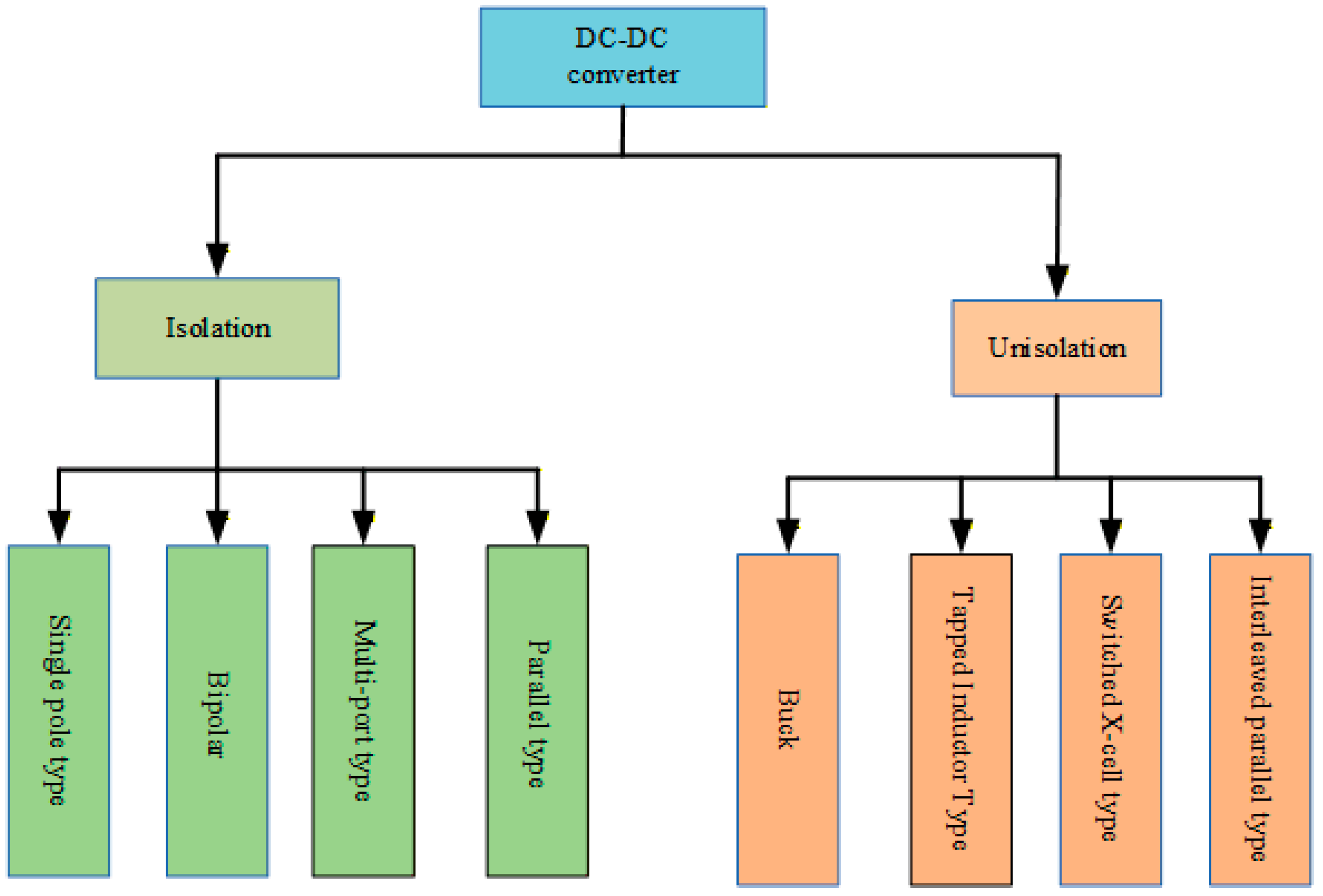
Hydrogen production power sources can be categorized into two types based on their electrical energy sources. For DC power from PV systems, DC-DC converters are required to supply power to electrolyzers. Conversely, AC power from grids or wind turbines necessitates AC-DC converters to convert alternating current into direct current for electrolyzer operation [17]. As shown in Figure 1, DC-DC converters can be further classified, according to their topology, into isolated and non-isolated types. Currently, non-isolated DC-DC converters predominantly adopt Buck circuits as their foundation. However, due to inherent structural limitations of Buck circuits, most non-isolated converters exhibit significant current ripple, making them suitable only for hydrogen production scenarios with minimal voltage ratio variations and no electrical isolation requirements [18]. In contrast, isolated DC-DC converters incorporate high-frequency transformers that not only reduce secondary-side voltage but also provide electrical isolation between primary and secondary circuits.
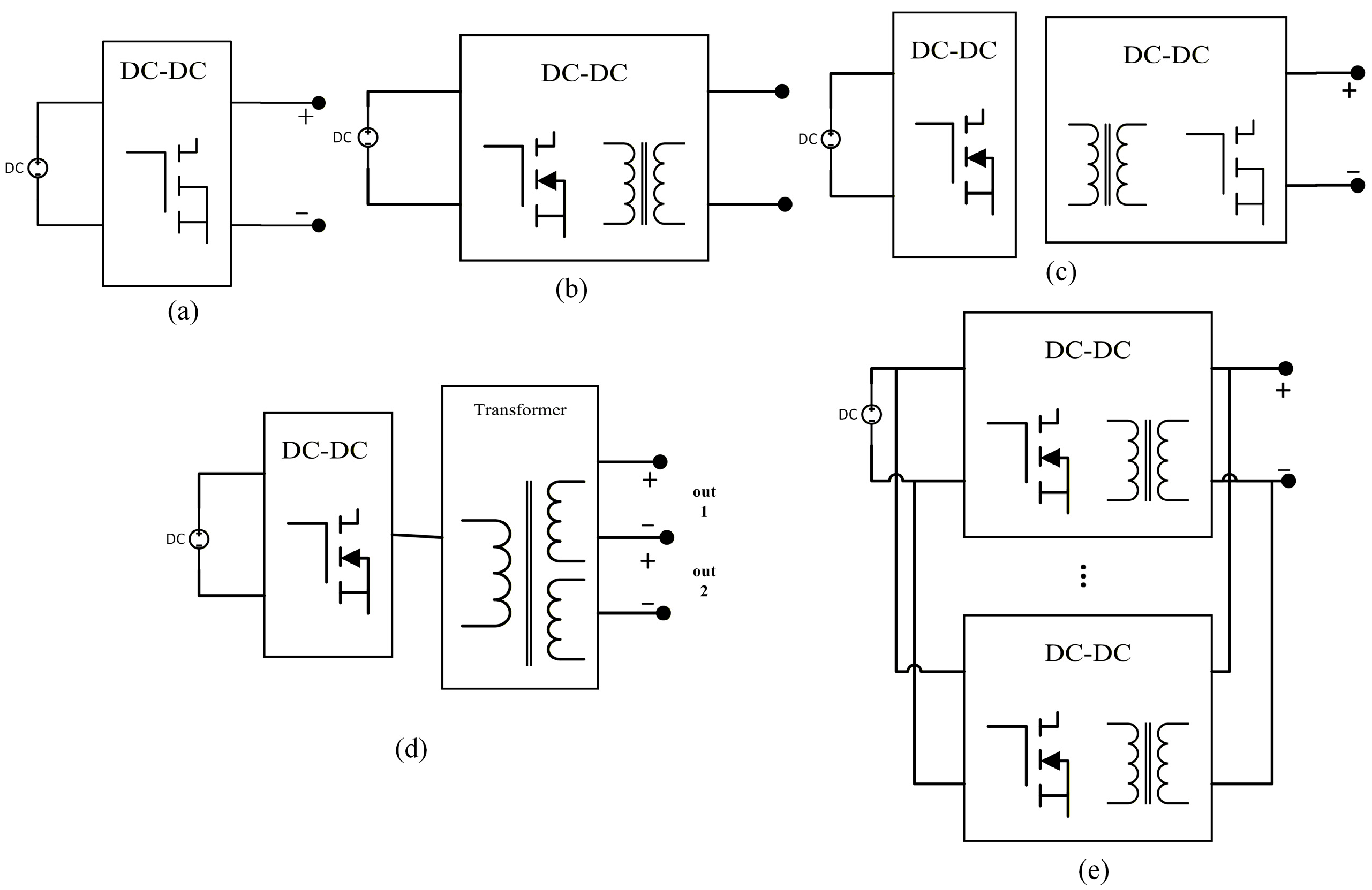
As shown in Figure 2, hydrogen production power sources with isolated converters can be categorized into single-stage, two-stage, parallel, and multi-port configurations [19], with their circuit topologies illustrated in Figure 2.

2.2. Topological Structure Analysis of New Energy Hydrogen Production System

The unique climatic conditions in northwest China, such as high sunshine hours and strong wind energy resources, provide distinctive advantages for the efficient utilization of renewable energy [20]. Based on these characteristics, we propose an innovative control strategy for renewable hydrogen production systems aimed at maximizing the conversion and utilization of these energy sources to enhance hydrogen production efficiency and system economics.
In the proposed system, the grid-side converter and the hydrogen production converter are dynamically coupled through the common DC-link energy balance. As a result, AC-side power regulation and DC-side bus stabilization should not be considered as completely isolated control tasks. This coupling provides the basis for introducing a coordinated dual virtual motor control strategy.
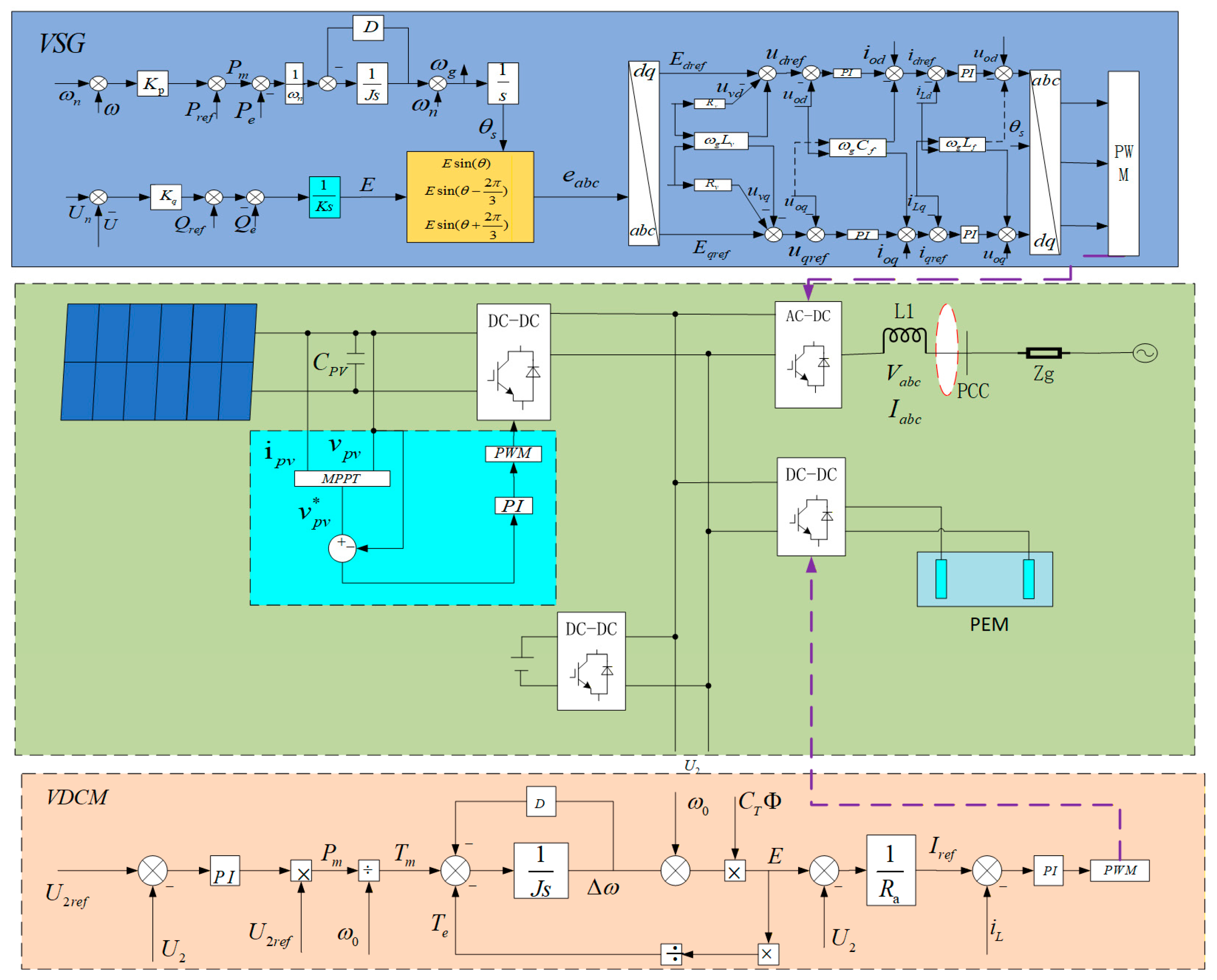
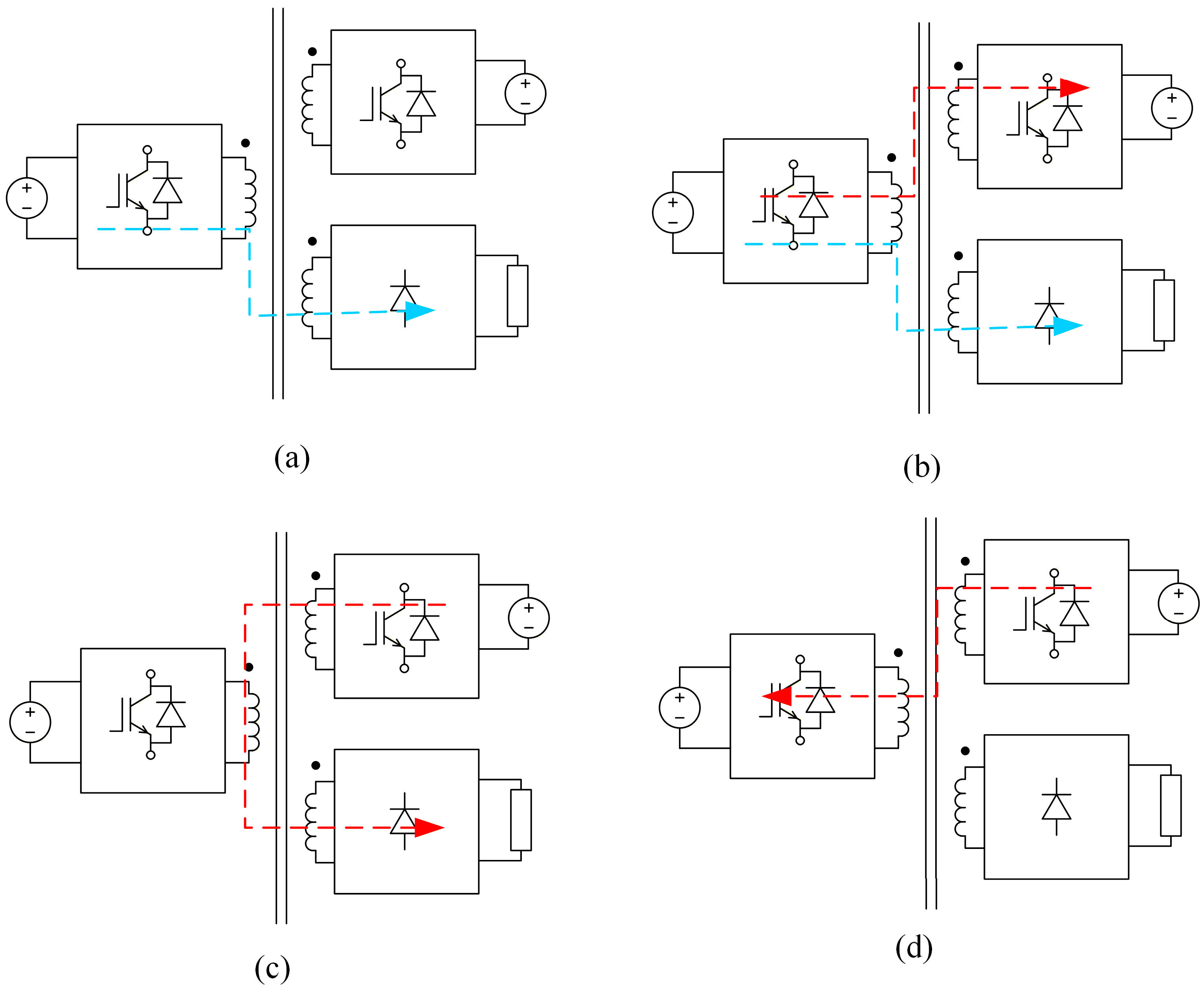
As shown in Figure 3, advanced PV power generation technology is employed alongside high-performance water electrolysis technologies (such as proton-exchange membrane electrolyzers) to achieve efficient energy conversion. On the grid interface side, the converter performs DC-AC conversion to connect the DC bus to the utility AC grid, whereas the electrolyzer-side converter regulates the DC voltage and current supplied to the hydrogen production unit. Considering solar irradiance fluctuations, as illustrated in Figure 4, the hydrogen production power source operates in four modes. In summary, the designed hydrogen production power source, based on the renewable energy features of northwest China, not only considers the efficient conversion and utilization of energy but also fully addresses system reliability and economic viability [21].
It is expected to play a pivotal role in advancing green energy transition and hydrogen economy development across northwest China and beyond.

3. Research on Control Strategy of Network-Type Converter

3.1. Principle and Limitations of Droop Control

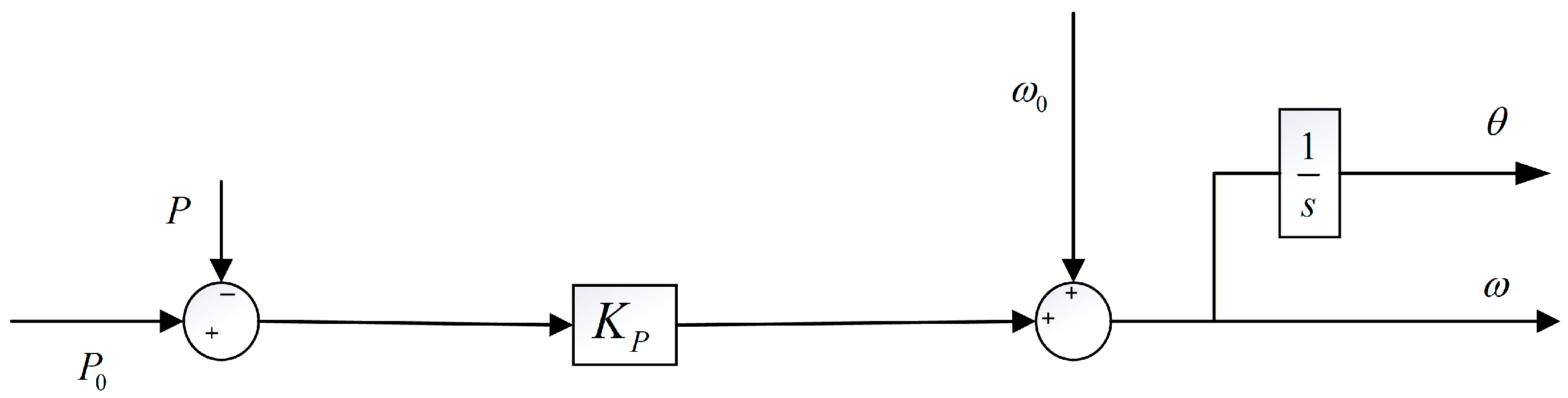
Droop control is the most common and simplest control strategy among all kinds of grid-forming (GFM) control strategies [22]. The droop control characteristic expression for frequency is given by Equation (1).
ω = ω 0 + K P ( P 0 P ) θ = ω d t
where ω and θ are output values of angular frequency and power angle, respectively; ω 0 is the reference value of angular frequency; P 0 is the reference value of output power; P is the detection value of output power; K P is the droop coefficient; t is the running time. The difference between the reference active power and the measured active power, multiplied by the droop coefficient, determines the frequency adjustment term.
The droop control block diagram is shown in Figure 5, where ω is the Laplacian operator. The advantages of droop control are simple structure and control and fast response speed, but the converter under this control mode does not have the inherent inertia and damping characteristics of synchronous generator operation [23].

3.2. Virtual Synchronous Machine Control

Virtual synchronous generator (VSG) technology plays a pivotal role in renewable hydrogen production systems, providing a stable and controllable power interface for electrolysis processes utilizing high-proportion renewable energy sources. In scenarios where fluctuating power sources like wind turbines and PV systems directly drive electrolyzers, VSG effectively mitigates power fluctuations through multi-dimensional control mechanisms, ensuring safe and efficient operation of hydrogen production systems. The core principle of VSG control lies in simulating the electromagnetic and mechanical transient characteristics of synchronous generators during their operational phases [24], enabling converters to exhibit inertial and damping properties comparable to those of actual synchronous generators.
At the electromagnetic transient level, VSG suppresses voltage spikes at grid connection points through virtual impedance–excitation coupling, preventing protection tripping in electrolyzers caused by transient overvoltages. Its current differential feedforward mechanism enhances traversal capability against grid short-circuit faults [25], significantly improving the continuous operational reliability of hydrogen production systems during grid disturbances. At the electromechanical transient scale, VSG provides virtual inertia and damping by simulating rotor swing equations. This enables rapid power release or absorption during frequency fluctuations, mitigating the impact of renewable energy power fluctuations on electrolysis processes, thereby maintaining power stability and efficiency of hydrogen production facilities.
The VSG achieves primary frequency regulation and automatic reactive power distribution through active-frequency/reactive-voltage droop control, coordinating power sharing among multiple hydrogen production converter units without requiring additional communication, adapting to various operating conditions, including off-grid and weak-grid scenarios. To mitigate the risk of subsynchronous oscillations caused by fluctuations in wind and solar resources, the VSG incorporates a narrowband chopper to suppress resonance in specific frequency bands, while maintaining system dynamic response consistency through an energy-preserving discretization algorithm [26]. During faults, the VSG switches to current-limiting mode to protect power components in the hydrogen converter from overcurrent damage.
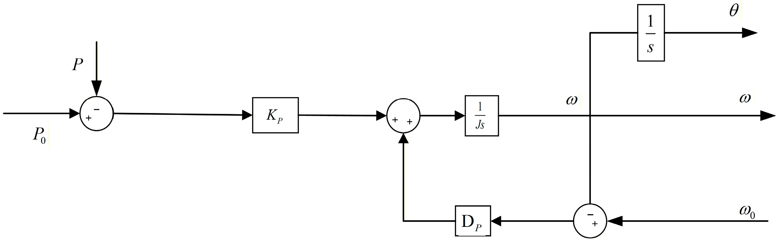
The P-f control branch of the VSG simulates primary frequency regulation and rotor motion, as shown in Figure 6, to characterize P-f droop characteristics. The mathematical expression is
ω = 1 J s ( D P ( ω 0 ω ) + K P ( P 0 P ) )
where is the moment of inertia; specifically, J is the moment of inertia and D is the damping coefficient. The simplified form of (3) can be obtained as
ω = K P J s + D P ( P 0 P ) + ω 0
Comparing Equation (1) with Equation (3), the VSG control strategy can be understood as adding a damping inertia component to the droop control strategy. This means VSG control not only simulates the regulation characteristics of primary frequency and voltage control but also incorporates the inertia and damping properties of synchronous generators through the introduction of rotational inertia and damping coefficients. VSG technology can comprehensively simulate the dynamic behavior of synchronous generators on millisecond-to-minute time scales, providing essential inertia and damping support for renewable hydrogen production systems while significantly enhancing their grid adaptability and operational resilience. This makes it a key enabling technology for achieving large-scale green hydrogen production and grid integration [27].

4. Consider the Optimization of Control Strategy for Hydrogen Production Load Characteristics

4.1. Hydrogen Production Load Characteristics

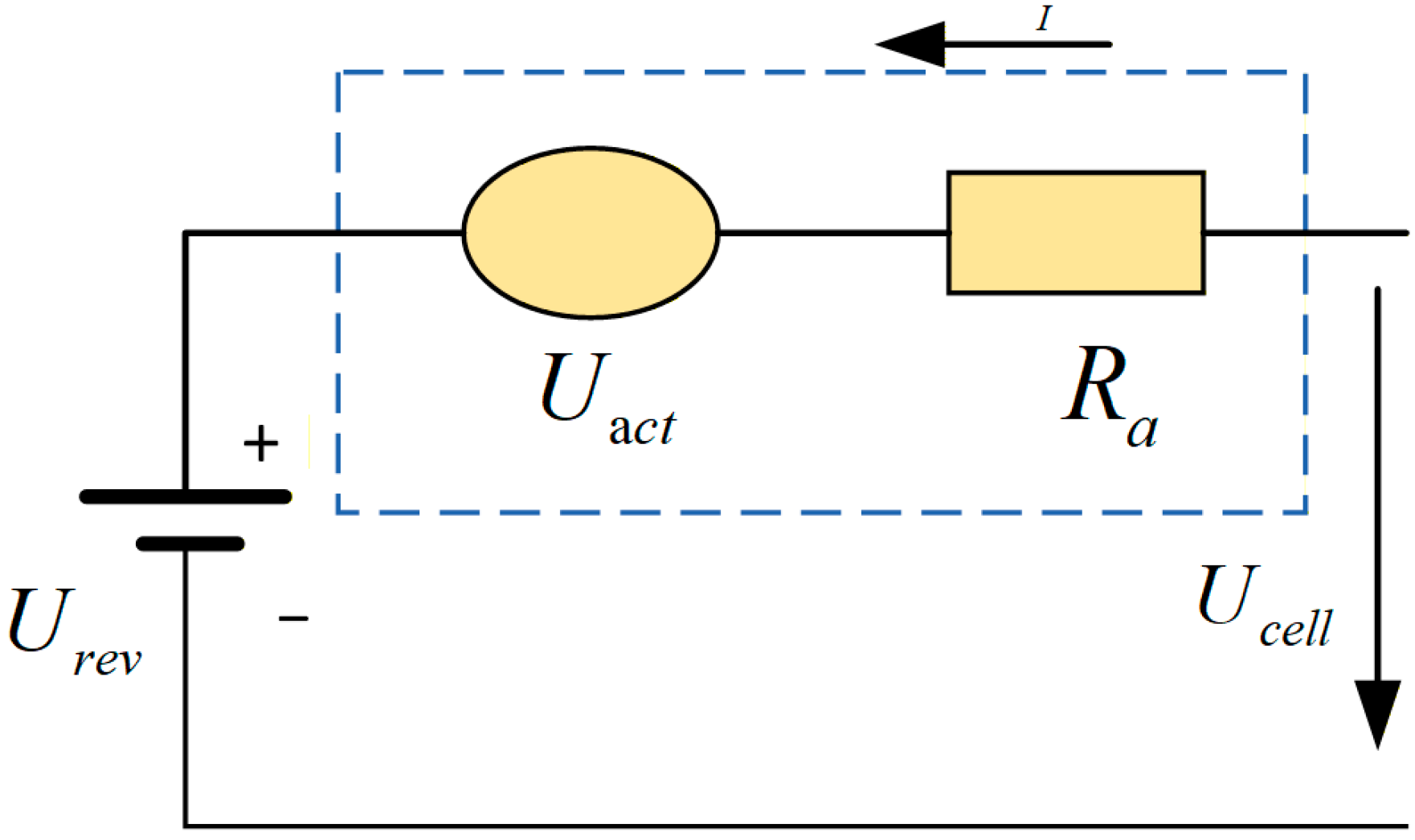
The electrolyzer is one of the key pieces of equipment in hydrogen production [28], and its simplified equivalent circuit is shown in Figure 7. In this paper, the electrolyzer is approximated as an equivalent resistive load around a nominal operating point for the purpose of control-oriented analysis. This approximation is reasonable when the electrolyzer operates near a stable working condition and when the thermal and pressure dynamics are much slower than the converter control dynamics. Under these conditions, the voltage–current relationship of the electrolyzer can be linearized, and a simplified equivalent resistance model can be used to describe its external electrical behavior. Nevertheless, this is a simplified model rather than a complete physical representation. Under large-signal transients, temperature variation, pressure change, and nonlinear electrochemical polarization effects, the electrolyzer exhibits more complex nonlinear behavior. Therefore, the resistive-load assumption adopted here is mainly intended for small-signal dynamic analysis and controller design.
Where U c e l l is the cell voltage, U r e v is the reversible voltage, R o h m is the equivalent resistance, and P and I are the current flowing through the equivalent resistance. Electrical external characteristics can be expressed as
U c e l l ( T , P ) = U r e v ( T , P ) + I R o h m ( T , P )
In the formula, T and P represent temperature and pressure, respectively. As shown in Equation (4), when temperature and pressure remain constant, the voltage across the electrolytic cell maintains a linear relationship with the current flowing through it, indicating that the cell behaves as a resistive load. Therefore, under these stable conditions, a definite correlation exists between the input power and current of the electrolytic cell [29].

4.2. Virtual DC Motor Control for Hydrogen Production Load

In order to improve the dynamic response capability of the DC bus of the hydrogen production system, the mechanical equation and electromotive force balance equation of VDCM are introduced into the DC/DC converter [30] of the energy storage system. See Figure 8 for the specific control block diagram.
The strategy includes voltage outer-loop control, VDCM control, and current inner-loop control. Bus voltage U 2 is equivalent to the DC generator terminal voltage U a , output current i o u t is equivalent to the DC generator armature current i a , so that the energy storage DC/DC converter has external characteristics similar to the DC generator [31].
The electric balance equation is
E a = U a + i a R a
where E a is armature voltage, E a = C T Φ ω , C T is the torque coefficient, Φ is magnetic flux, ω is the DC generator mechanical angular velocity, U a is the virtual generator terminal voltage, and R a is armature resistance.
The mechanical equation of the DC generator is
J d ω d t = T m T e D ( ω ω 0 )
VDCM mechanical power and electromagnetic power are expressed as
P m = T m ω T m ω 0 P e = T e ω E a i a
Compared with conventional DC bus control schemes, the main advantage of the VDCM strategy in this study is that it introduces a virtual electromechanical inertia-damping mechanism into the DC/DC converter control process. As a result, the converter exhibits a dynamic buffering effect similar to that of an electromechanical energy conversion unit, which helps suppress abrupt bus voltage variations during renewable power and load disturbances. In addition, this approach can improve transient damping without relying solely on a large physical DC capacitor. However, the present study does not claim that VDCM is universally superior to all advanced control methods. Rather, it is shown to be an effective and practically attractive solution for the considered PV–hydrogen production scenario.

4.3. Small-Signal Analysis

To improve the rigor and clarity of the modeling process, the small-signal model of the VDCM-controlled subsystem is derived step by step from the electrical equation and mechanical equation of the virtual DC motor. First, the nonlinear-state equations are established. Then, small perturbations are introduced around the steady-state operating point. By neglecting higher-order perturbation terms and applying Laplace transformation, the corresponding small-signal transfer relationship is obtained. All variables and parameters involved in the derivation are explicitly defined below.
Based on the electrical balance equation and mechanical equation of the VDCM, the nonlinear dynamic model of the controlled subsystem can first be expressed in state-space form. Let the steady-state operating point be denoted by ω 0 , and define the small perturbation variables as
ω = ω ω 0
H ω ˙ = T m C T 2 Φ 2 ω 0 R a C T 2 Φ 2 ω R a D ( ω ω 0 )
H = J ω 0 2 1 S n
The disturbance term is added to Equation (9)
H ( ω ˙ + ω ^ ˙ ) = ( T m + T m ^ ) C T 2 Φ 2 ω 0 R a C T 2   Φ 2   R a ( ω + ω ^ ) D ( ω + ω ^ )
After separation and perturbation, we can get
H ω ^ ˙ = T m ^ C T 2 Φ 2 R a ω D ω ^
Variable substitution has
H ω ^ ˙ = T m C T 2 Φ 2 R a ω D ω
The virtual DC motor small-signal model can be obtained by Laplace transform
G G ( s ) = 1 H s C T 2 Φ 2 R a + D
The virtual DC generator [32] can be approximated as a first-order inertial element containing an energy storage component, with its time constant corresponding to that of the first-order inertial element. This virtual DC generator functions as a variable-capacitance “virtual capacitor” connected in parallel to the output of the DC/DC converter. By adjusting the parameters of the virtual DC generator [33], its capacitance value can be modified, thereby enabling the DC bus voltage to exhibit a certain degree of “inertia”. This effectively suppresses and buffers disturbances to the DC bus voltage, maintaining its stability and improving power quality.
From Equation (14), we can get
U = C T Φ ω I R a
According to Equation (15), the relationship between voltage deviation and angular velocity deviation is
U ω = C T Φ
Therefore, the small-signal model of the virtual DC generator is shown in Figure 9.
From Figure 9, the transfer function between the DC converter port output voltage deviation U and DC bus voltage deviation U 2 in virtual DC generator control technology can be obtained as follows:
G G ( s ) = U r e f C T Φ R a ( k p s + k i ) H R a ω 0 s 2 + ( C T 2 Φ 2 ω 0 + D R a ω 0 ) s
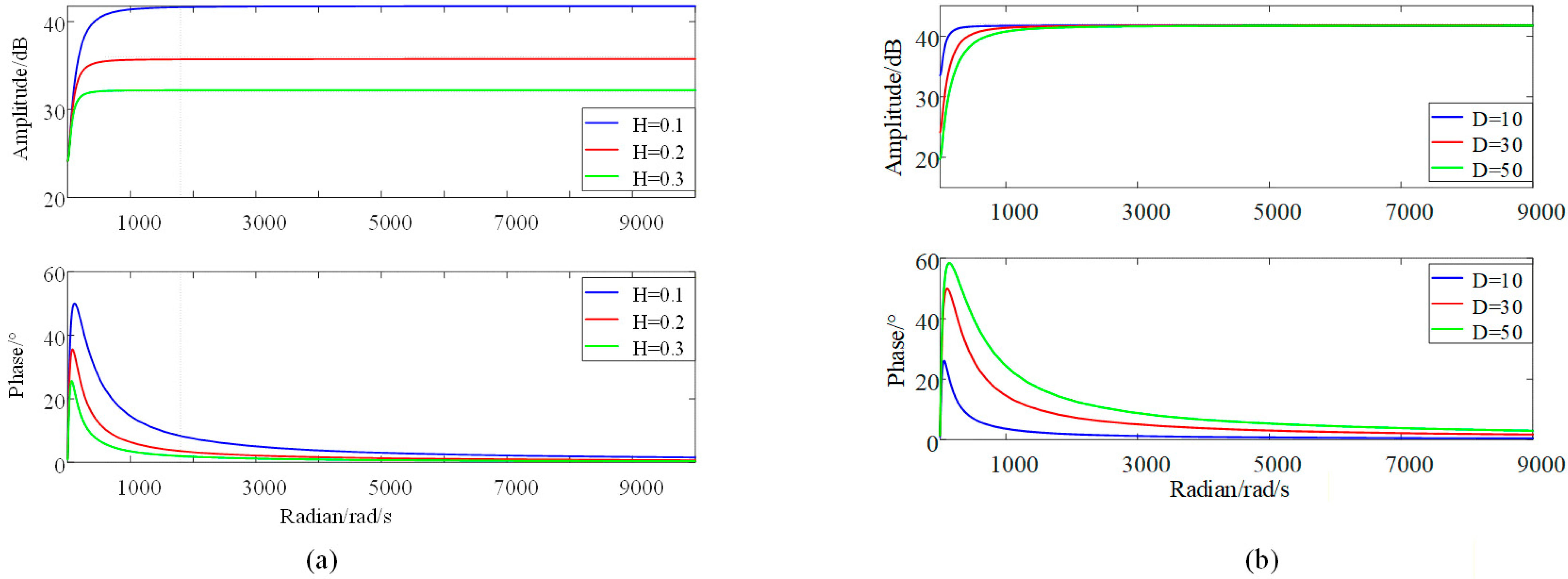
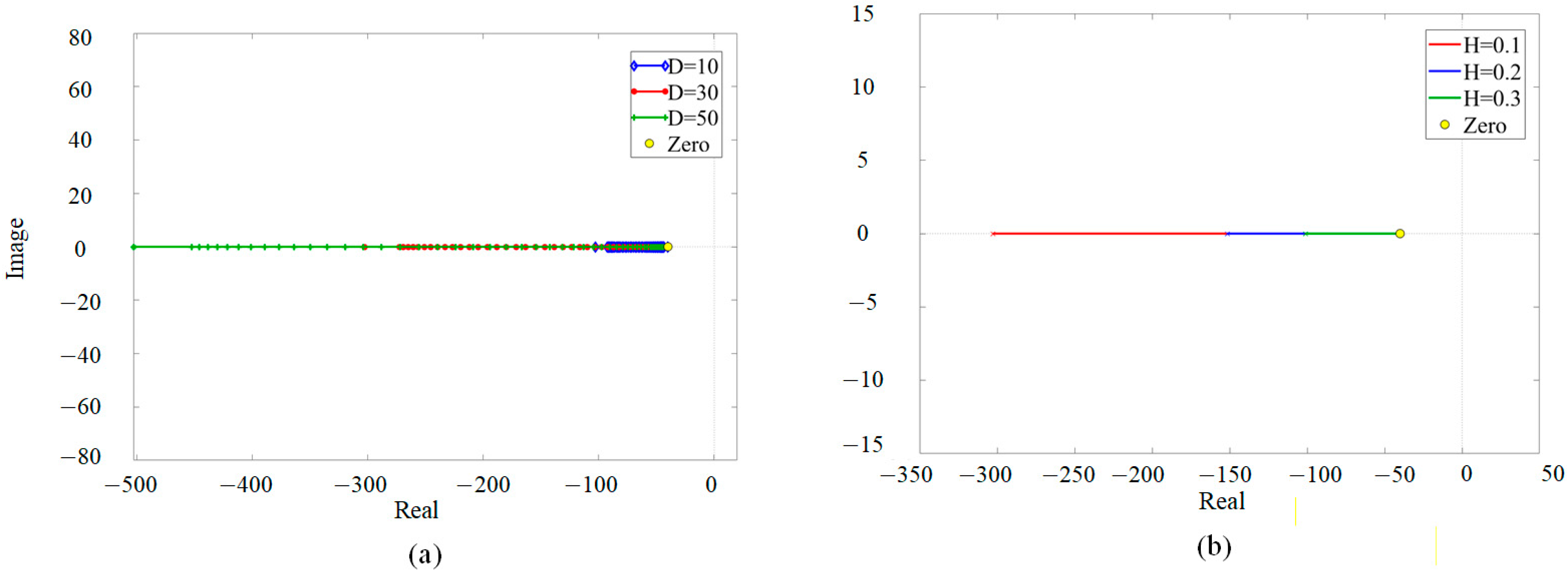
Select parameters are shown in Table 2. Substitute the parameters and plot the Bode diagram and root locus diagram of the system [34] when the inertia time constant H and damping coefficient D change, as shown in Figure 10 and Figure 11.
The closed-loop transfer function poles of VDCM are located on the left side of the real axis, and the poles gradually move away from the imaginary axis with the increase in moment of inertia J , so that the system stability margin increases, the overshoot decreases, and the recovery time decreases.
The quantitative pole locations and corresponding time constants are reported in Table 3. The nominal choice H V = 0.10 and D V = 30 provides a compromise between response speed and damping.
When the damping coefficient D gradually increases, the system poles gradually approach the imaginary axis, the overshoot increases, the oscillation increases, and the recovery time becomes longer. To sum up, inertia J and damping coefficient D have great influence on the dynamic response of the system. In order to ensure the stability and dynamic performance of the control strategy, it is necessary to select the values of inertia J and damping D reasonably [35]. The dynamic performance of the proposed control strategy is strongly influenced by the parameters of the virtual electromechanical model and the outer-loop controllers. In general, the virtual inertia J mainly affects the equivalent inertial response and transient speed, while the damping coefficient D mainly affects oscillation suppression and damping performance. In addition, the proportional and integral gains of the voltage/current loops determine the loop bandwidth and dynamic interaction. A practical tuning procedure is to first tune the inner current loop, then the outer voltage loop, and finally adjust J and D according to the desired trade-off between response speed and damping. Excessively large inertia may lead to slower recovery, whereas insufficient damping may increase oscillatory behavior.

5. Case Analysis

5.1. VSG Active Support Verification Under Frequency Variation

To evaluate the proposed strategy more rigorously, the case studies in this section consider both waveform-based observation and quantitative transient-performance indices. In addition to conventional control, representative baseline methods such as double closed-loop DC bus control and droop-based regulation are discussed for comparison where applicable. In the light–hydrogen–storage system, variations in illumination directly affect the system’s output power [36].
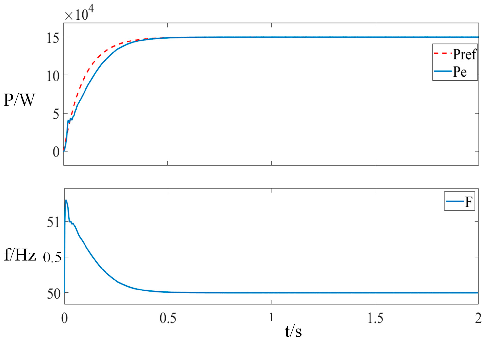
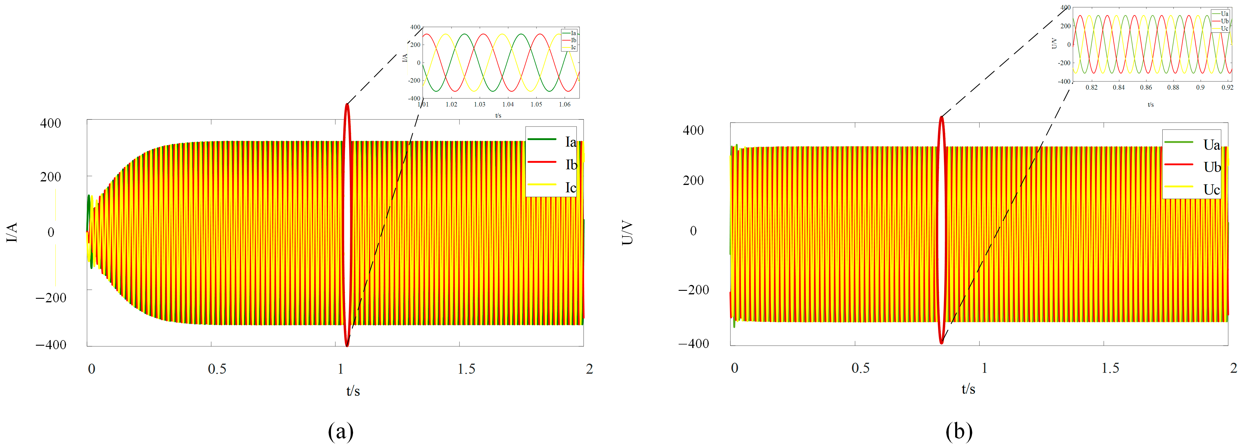
To verify the power support capability of the grid-connected VSG (virtual synchronous generator) under illumination changes for the electro-hydrogen production system, we introduced a disturbance at 0.6 s and gradually restored rated operation at 1.2 s. As shown in Figure 12 and Figure 13, the power, voltage, and current remained stable with frequency and active power maintained at constant levels. The system demonstrated significant inertia, effective grid integration, and minor fluctuations in the PCC current and voltage.

5.2. Comparative Analysis of Different Control Strategies of Electrolytic Cells

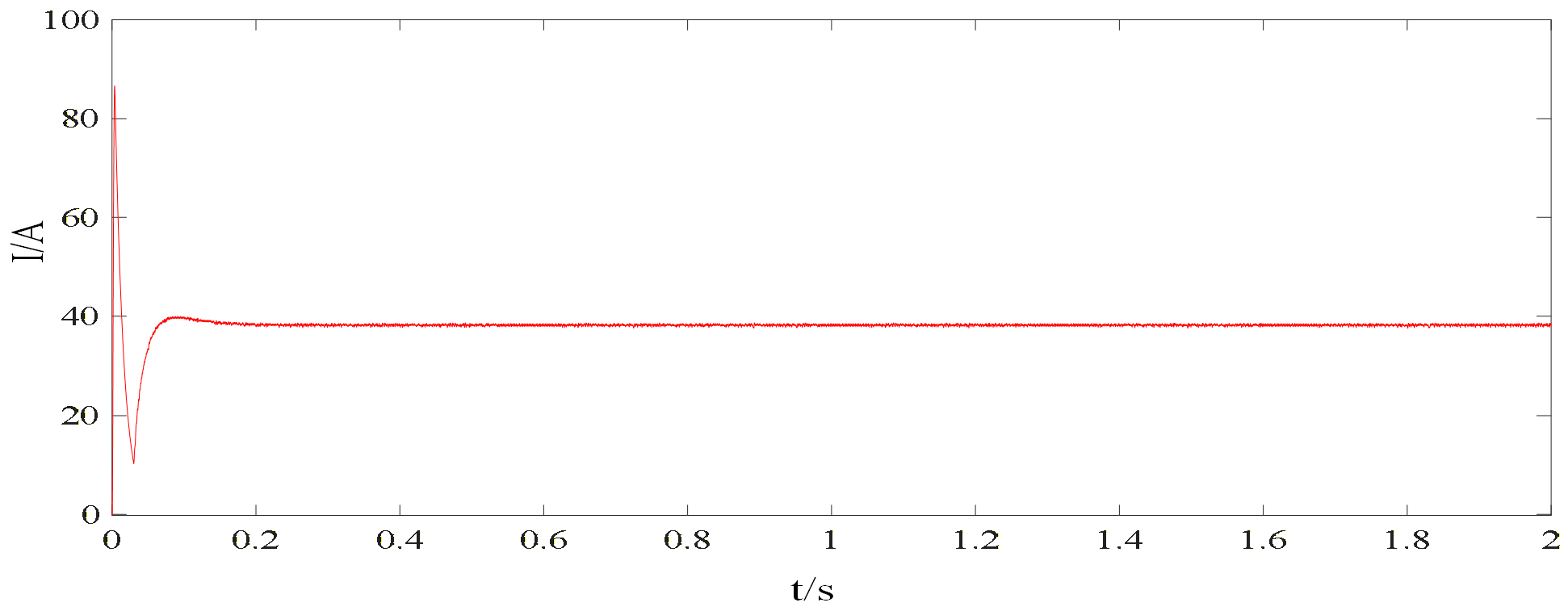
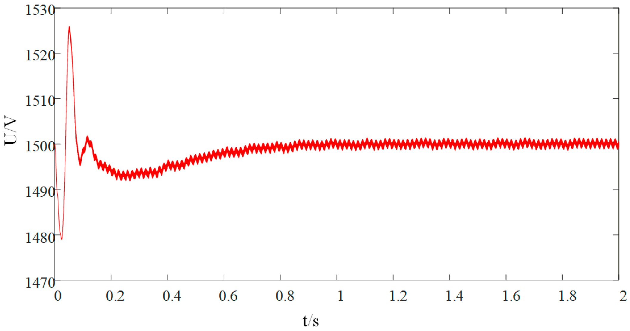
The stability of the DC bus is critical for hydrogen production systems. Traditional electrolyzers employ dual closed-loop constant power control for voltage and current, as shown in Figure 14 and Figure 15.
However, frequent start–stop cycles in renewable energy generation systems can cause significant DC bus current surges, leading to voltage fluctuations and even equipment damage.
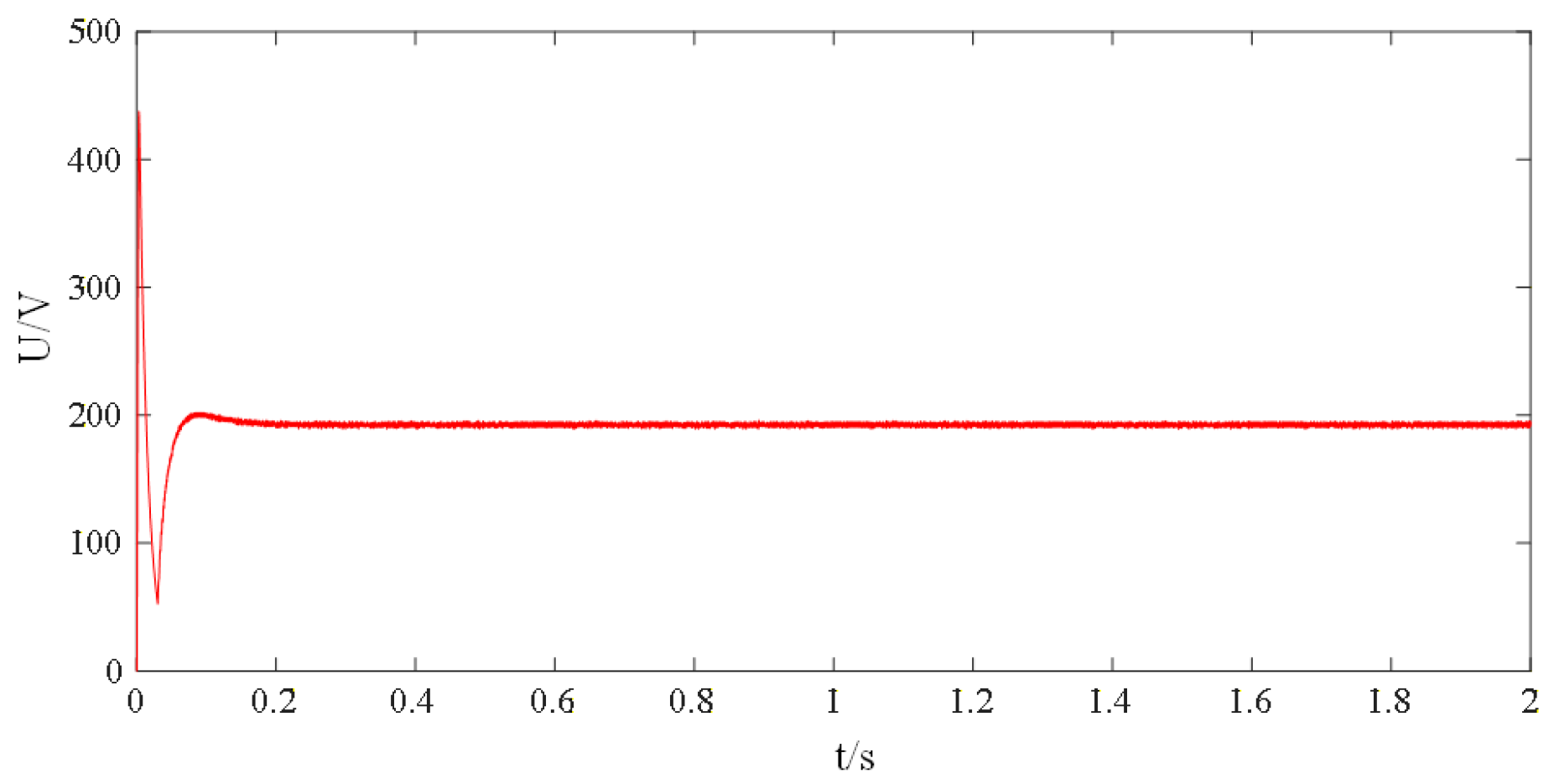
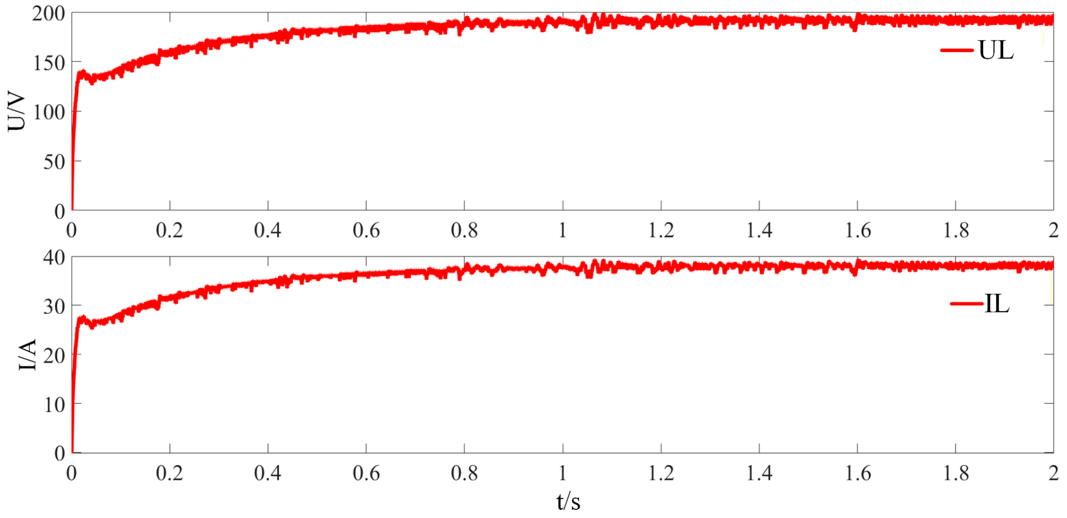
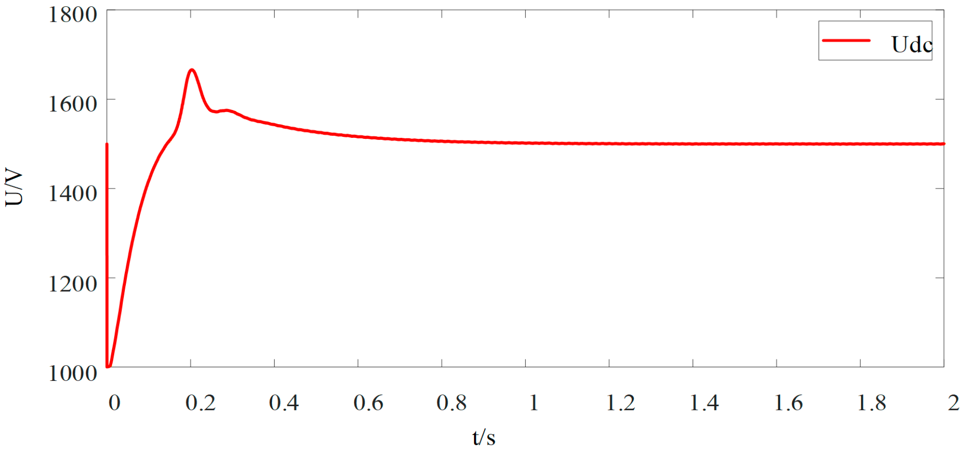
After adopting the virtual DC motor (VDCM) control strategy, as illustrated in Figure 16, Figure 17 and Figure 18, the voltage and current response speeds are relatively slowed down.
This is due to the DC/DC converter simulating the mechanical inertia and damping characteristics of the DC generator, resulting in a lagging electrical current dynamic.
To make the comparison less purely visual, Table 4 summarizes approximate transient metrics read from the waveform plots. Although these values are not produced by a dedicated automated post-processing routine, they are sufficient to reveal the dominant trade-off between aggressive tracking and disturbance buffering.
Based on the approximate readings in Table 4, the proposed VDCM strategy suppresses the DC bus overshoot from about 125% to nearly zero and reduces the peak current from about 90 A to 40 A, i.e., by roughly 55.6%. The cost is a slower but smoother response. Therefore, within the scope of the present study, the main demonstrated advantage of the VDCM is not the fastest tracking but reduced DC bus stress and improved disturbance buffering. A broader benchmark against droop-only control, more severe weak-grid cases, and parameter uncertainty is an important next step and is now acknowledged explicitly in the revised paper.
This characteristic effectively suppresses severe fluctuations in bus current and voltage, significantly enhancing the operational stability and robustness of the hydrogen production system’s DC side. It should be emphasized that the AC-side VSG and the DC-side VDCM are dynamically coupled through the shared DC-link power balance. Therefore, AC-side active power regulation and DC-side voltage stabilization are not completely independent. In principle, inappropriate parameter matching may introduce adverse interaction or coupled oscillation. In the proposed framework, this risk is mitigated by assigning different dominant control objectives to the two interfaces and by ensuring sufficiently fast inner-loop damping. Under the selected parameter settings and studied disturbances, no harmful coupled oscillation is observed in the simulation results.

6. Conclusions

To address challenges in weak-grid-connected PV–hydrogen–storage systems—including limited voltage/frequency regulation capabilities and system instability caused by hydrogen production system inertia/damping deficiencies—this study proposes a grid-connected virtual motor control strategy to enhance stability.
Key findings are as follows: (1) During active power fluctuations, the grid-connected VSG strategy rapidly compensates for power deficits while maintaining system frequency within normal ranges. For reactive power fluctuations, it optimally distributes active/reactive power and stabilizes PCC voltage, ensuring reliable frequency/voltage support. (2) Compared to traditional control methods, the VDCM strategy provides inertial damping support to hydrogen production DC busbars, effectively preventing voltage spikes during load switching and ensuring system stability. With large-scale renewable energy integration and rapid hydrogen production system development, PV–hydrogen–storage systems are poised to become a cornerstone of future energy grids, making coordinated stability control research particularly crucial. This study establishes theoretical foundations for large-scale renewable hydrogen production and efficient PV–hydrogen–storage system operation.

Author Contributions

Conceptualization, B.L.; methodology, B.L.; software, B.L.; validation, B.L.; formal analysis, A.A., F.W. and B.L.; investigation, B.L.; writing—original draft preparation, B.L.; writing—review and editing, B.L. and A.T.; supervision, A.T.; project administration, A.T.; funding acquisition, A.T. All authors have read and agreed to the published version of the manuscript.

Funding

This research was funded by the National Natural Science Foundation of China, grant number 72561027; The Xinjiang Uygur Autonomous Region Department of Education, Xinjiang Uygur Autonomous Region High-Efficiency Basic Scientific Research Fund Project, grant number XJEDU2023P027; Curriculum reform of new energy power electronic technology driven by the integration of production and education, grant number XJGXJGPTA-2025006.

Data Availability Statement

The original contributions presented in the study are included in the article. Further inquiries can be directed to the corresponding author.

Conflicts of Interest

The authors declare no conflicts of interest.

Abbreviations

The following abbreviations are used in this manuscript:
PVPhotovoltaic
VSGVirtual Synchronous Generator
VDCMVirtual DC Motor
PEMProton-Exchange Membrane Electrolyzer

References

  1. Tian, C.; Tan, Q.; Fang, G.; Wen, X. Hydrogen production to combat power surpluses in hybrid hydro–wind–PV power systems. Appl. Energy 2024, 371, 123627. [Google Scholar] [CrossRef] [Scilit]
  2. Wang, W.; Li, X.; Chu, L. Review of research on friendly grid integration and operation control technology for large-scale renewable energy power generation. J. Xinjiang Univ. (Nat. Sci. Ed.) 2024, 41, 129–144+156. [Google Scholar] [CrossRef]
  3. She, B.; Li, F.; Cui, H.; Zhang, J.; Bo, R. Fusion of Microgrid Control With Model-Free Reinforcement Learning: Review and Vision. IEEE Trans. Smart Grid 2023, 14, 3232–3245. [Google Scholar] [CrossRef] [Scilit]
  4. Valdés, R.; Lucio, J.H.; Rodríguez, L.R. Operational simulation of wind power plants for electrolytic hydrogen production connected to a distributed electricity generation grid. Renew. Energy 2013, 53, 249–257. [Google Scholar] [CrossRef] [Scilit]
  5. El Mezdi, K.; El Magri, A.; El Myasse, I.; Giri, F.; Kumar, P. Energy flow optimization for a hybrid DC-microgrid integrating hydrogen production via a PEM electrolyzer and fuel cell backup. Int. J. Electr. Power Energy Syst. 2026, 175, 111568. [Google Scholar] [CrossRef] [Scilit]
  6. Jin, J.; Wang, Z.; Chen, Y.; Xie, C.; Wu, F.; Wen, Y. Modeling and energy management strategy of hybrid energy storage in islanded DC micro-grid. Electr. Eng. 2024, 106, 6665–6679. [Google Scholar] [CrossRef] [Scilit]
  7. Tang, Y.; Qian, X.; Cai, Z.; Liserre, M.; Yang, H. Energy management of electric-hydrogen hybrid energy storage systems in photovoltaic microgrids. Int. J. Hydrogen Energy 2024, 80, 1–10. [Google Scholar] [CrossRef] [Scilit]
  8. Ulleberg, Ø.; Nakken, T.; Eté, A. The wind/hydrogen demonstration system at Utsira in Norway: Evaluation of system performance using operational data and updated hydrogen energy system modeling tools. Int. J. Hydrogen Energy 2010, 35, 1841–1852. [Google Scholar] [CrossRef] [Scilit]
  9. Cheng, J.; Meng, J.; Bao, G.; Hu, X. Control of DC Bus Voltage in a 10 kV Off-Grid Wind–Solar–Hydrogen Energy Storage System. Energies 2025, 18, 2328. [Google Scholar] [CrossRef] [Scilit]
  10. Trifkovic, M.; Sheikhzadeh, M.; Nigim, K.; Daoutidis, P. Modeling and control of a renewable hybrid energy system with hydrogen storage. IEEE Trans. Control Syst. Technol. 2014, 22, 169–179. [Google Scholar] [CrossRef] [Scilit]
  11. García, P.; Torreglosa, J.P.; Fernández, L.M.; Jurado, F.; Langella, R.; Testa, A. Energy management system based on techno-economic optimization for microgrids. Electr. Power Syst. Res. 2016, 131, 49–59. [Google Scholar] [CrossRef] [Scilit]
  12. Fang, X.; Zhong, X.; Dong, W.; Zhang, F.; Yang, Q. Fuzzy logic-based coordinated operation strategy for an off-grid PV hydrogen production system with battery/supercapacitor hybrid energy storage. Int. J. Hydrogen Energy 2024, 84, 593–605. [Google Scholar] [CrossRef] [Scilit]
  13. Zhao, D.; Pei, J.; Bai, J.; Xu, C.; Song, C.; Liu, C. Research on frequency regulation capability improvement technology of grid-forming converters in weak and extremely weak grid scenarios. Proc. CSEE 2024, 44, 215–226. [Google Scholar] [CrossRef]
  14. Li, C.; Yang, Y.; Mao, X.; Xiong, X.; Dragicevic, T. Modeling, control and stabilization of virtual synchronous generator in future power electronics-dominated power systems: A survey of challenges, advances, and future trends. Int. J. Electr. Power Energy Syst. 2025, 171, 111001. [Google Scholar] [CrossRef] [Scilit]
  15. Yuan, T.; Zhang, J.; Teng, Y. Coordinated Control Strategy of the Renewable Energy Hydrogen Production System Based on VSG. Proc. CSEE 2025, 45, 163–175. [Google Scholar] [CrossRef]
  16. He, B.; Ren, Y.; Xue, Y.; Yun, P.; Dong, X. Interleaved Parallel VDCM Improves Stability Control of Wind Power-Hydrogen Coupled Integrated System. Int. J. Electr. Power Energy Syst. 2025, 172, 111341. [Google Scholar] [CrossRef] [Scilit]
  17. Kong, L.; Gong, J.; Yang, S.; Ni, D.; Wang, S.; Liu, C. Development status and trend of DC/DC isolated hydrogen production power supply. Power Gener. Technol. 2023, 44, 443–451. [Google Scholar] [CrossRef]
  18. Tang, Z.; Yang, Y.; Blaabjerg, F. An interlinking converter for renewable energy integration into hybrid grids. IEEE Trans. Power Electron. 2021, 36, 2499–2504. [Google Scholar] [CrossRef] [Scilit]
  19. Hassan, A.; Abdel-Rahim, O.; Bajaj, M.; Zaitsev, I. Power electronics for green hydrogen generation with focus on methods, topologies, and comparative analysis. Sci. Rep. 2024, 14, 27667. [Google Scholar] [CrossRef] [Scilit] [PubMed]
  20. Zhou, J.; Ji, C.; Li, R.; Song, X.; Wu, K.; Cheng, Y. Recent development in the technology of water electrolysis hydrogen production and its application in new power systems. High Volt. Eng. 2025, 51, 2096–2113. [Google Scholar] [CrossRef]
  21. Ge, L.; Zhang, B.; Huang, W.; Li, Y.; Hou, L.; Xiao, J.; Mao, Z.; Li, X. A review of hydrogen generation, storage, and applications in power system. J. Energy Storage 2024, 75, 109307. [Google Scholar] [CrossRef] [Scilit]
  22. Pishbahar, H.; Blaabjerg, F.; Saboori, H. Emerging grid-forming power converters for renewable energy and storage resources integration—A review. Sustain. Energy Technol. Assess. 2023, 60, 103538. [Google Scholar] [CrossRef] [Scilit]
  23. Torreglosa, J.P.; García, P.; Fernández, L.M.; Jurado, F. Energy dispatching based on predictive controller of an off-grid wind turbine/PV/hydrogen/battery hybrid system. Renew. Energy 2015, 74, 326–336. [Google Scholar] [CrossRef] [Scilit]
  24. Waskito, F.; Wijaya, F.D.; Firmansyah, E. Review of Virtual Inertia Based on Synchronous Generator Characteristic Emulation in Renewable Energy-Dominated Power Systems. Electricity 2025, 6, 69. [Google Scholar] [CrossRef] [Scilit]
  25. Yin, J.; Chen, Z.; Qian, W.; Zhou, S. A Virtual Synchronous Generator Low-Voltage Ride-Through Control Strategy Considering Complex Grid Faults. Appl. Sci. 2025, 15, 1920. [Google Scholar] [CrossRef] [Scilit]
  26. Pan, L.; Chen, L.; Pang, Y.; Chen, J.; Shi, F.; Li, R.; Liang, Y. Optimal operation control strategy for off-grid photovoltaic hydrogen production system considering coupled battery and hydrogen energy storage. J. Renew. Sustain. Energy 2024, 16, 065502. [Google Scholar] [CrossRef] [Scilit]
  27. Qiu, Y.; Zhu, J.; Zeng, Y.; Zhou, Y.; Zhou, B.; Li, W. Technological requirement analysis and prospect of energy management for off-grid renewable power-to-hydrogen systems. Autom. Electr. Power Syst. 2025, 48, 43–59. [Google Scholar] [CrossRef]
  28. Ulleberg, Ø. Modeling of advanced alkaline electrolyzers: A system simulation approach. Int. J. Hydrogen Energy 2003, 28, 21–33. [Google Scholar] [CrossRef] [Scilit]
  29. Xu, S.; Xi, X.; Shi, H.; Cheng, J.; Ma, H. Parameter Tuning and Adaptive Strategy for Grid-Forming Energy Storage Systems under Islanded-to-Grid-Connected Switching. Energies 2025, 18, 6541. [Google Scholar] [CrossRef] [Scilit]
  30. Gitau, M.N.; Adam, G.P.; Masike, L.; Mbukani, M.W.K. Unified approach for synthesis and analysis of non-isolated DC-DC converters. IEEE Access 2021, 9, 120088–120109. [Google Scholar] [CrossRef] [Scilit]
  31. Feng, P.; Yu, H.; Nie, G.; Sun, L.; Zhou, S.; Zhang, Z. Active frequency regulation strategy for electrolytic hydrogen production load based on current-type virtual synchronous machine control. Mod. Electr. Power 2024, 41, 1017–1022. [Google Scholar] [CrossRef]
  32. Qaisar, M.W.; Fang, J. Grid-Forming Converters for Renewable Generation: A Comprehensive Review. Energies 2025, 18, 4565. [Google Scholar] [CrossRef] [Scilit]
  33. He, B.; Ren, Y.; Meng, Q.; Yun, P.; Liu, H.; Mi, Y. Wind power hydrogen production system based on dual virtual motor control of grid-forming energy storage. High Volt. Eng. 2025, 51, 1867–1876. [Google Scholar] [CrossRef]
  34. Kang, J.; Wang, Y.; Wang, J.; Liu, B. Seamless Switching Control Strategy for a Power Conversion System in a Microgrid Based on Extended State Observer and Super-Twisting Algorithm. Electronics 2024, 13, 1708. [Google Scholar] [CrossRef] [Scilit]
  35. Xia, Y.; Chen, Y.; Wang, Y.; Chen, R.; Li, K.; Shi, J.; Yang, Y. A Virtual Synchronous Generator Control Strategy Based on Transient Damping Compensation and Virtual Inertia Adaptation. Appl. Sci. 2025, 15, 728. [Google Scholar] [CrossRef] [Scilit]
  36. Villalva, M.G.; Gazoli, J.R.; Filho, E.R. Comprehensive approach to modeling and simulation of photovoltaic arrays. IEEE Trans. Power Electron. 2009, 24, 1198–1208. [Google Scholar] [CrossRef] [Scilit]
Figure 1. Types of DC-DC converters.
Cleantechnol 08 00098 g001
Figure 2. Topological classification of DC-DC converters. (a) non-isolated type; (b) single-pole type; (c) bipolar type; (d) multi-port type; (e) parallel type.
Cleantechnol 08 00098 g002
Figure 3. Hydrogen production system and control strategy of renewable energy.
Cleantechnol 08 00098 g003
Figure 4. Grid-forming hydrogen production model. (a) renewable energy hydrogen production mode; (b) renewable energy + charging mode; (c) battery hydrogen production mode; (d) battery grid connection mode.
Cleantechnol 08 00098 g004
Figure 5. Droop control.
Cleantechnol 08 00098 g005
Figure 6. VSG control P-f loop.
Cleantechnol 08 00098 g006
Figure 7. Electrolytic cell.
Cleantechnol 08 00098 g007
Figure 8. VDCM control block diagram.
Cleantechnol 08 00098 g008
Figure 9. Small-signal model of the virtual DC generator.
Cleantechnol 08 00098 g009
Figure 10. Bode diagram of the VDCM-controlled loop. (a) effects of different inertial time constants; (b) effects of different damping coefficients.
Cleantechnol 08 00098 g010
Figure 11. Pole migration of the VDCM-controlled loop. (a) effects of different inertial time constants; (b) effects of different damping coefficients.
Cleantechnol 08 00098 g011
Figure 12. VSG frequency variation.
Cleantechnol 08 00098 g012
Figure 13. PCC voltage current. (a) PCC voltage; (b) PCC current.
Cleantechnol 08 00098 g013
Figure 14. Double closed-loop control voltage.
Cleantechnol 08 00098 g014
Figure 15. Double closed-loop control current.
Cleantechnol 08 00098 g015
Figure 16. Double closed-loop control bus voltage.
Cleantechnol 08 00098 g016
Figure 17. VDCM control voltage current.
Cleantechnol 08 00098 g017
Figure 18. VDCM control bus voltage.
Cleantechnol 08 00098 g018
Table 1. Comparison of representative studies and the present work.
StudyMain FocusAC-Side VSG/GFM SupportDC Bus Dynamic ShapingWeak-Grid FocusSmall-Signal Parameter Analysis
Valdes et al. (2013); Tang et al. (2024); Fang et al. (2024)Renewable hydrogen system operation and energy managementLimitedPartialLimitedNo
Cheng et al. (2025)DC bus voltage control in wind–solar–hydrogen systemNot primary focusYesNot emphasizedLimited
Yuan et al. (2025)Coordinated control of renewable hydrogen system based on VSGYesLimitedPartialLimited
He et al. (2025)Dual virtual motor-related stabilization in wind–hydrogen systemRelatedYesNot focused on PV weak-grid Point of common coupling (PCC) supportPartial
This workCoordinated AC/DC dynamic support for weak-grid PV–hydrogen production systemYesYesYesYes
Table 2. Base electrical and controller parameters used for the revised analytical study.
CategorySymbolValueUnit
AC base U B 6.6kV
Power base S B 1MVA
Base current I B 87.48A
Filter resistance R f 0.05Ω
Filter inductance L f 4.0mH
Filter capacitance C f 10.0μF
Nominal frequency f n 50Hz
Angular frequency ω 0 314.16rad/s
Reactance magnitude X f 1.2566Ω
Filter impedance magnitude Z 1.2576Ω
Filter impedance angle α 87.72deg
Control delay T d 1s
Droop/synchronization parameter δ 0.02-
VSG inertia J v s g 3.0-
VSG damping D v s g 15.92-
VSG active-power gain k f 25.46-
Auxiliary voltage U 380V
Internal EMF amplitude E 594V
Derived coupling coefficient K 179,622.27-
DC input voltage U i n 600V
Nominal DC output voltage U o u t 300V
Virtual back-EMF constant K e 1.2-
Virtual resistance R a 5Ω
Nominal virtual speed ω v 0   80rad/s
Outer-loop PI gains k p u , k i u 2.0, 80-
Inner-loop PI gains k p i , k i i 0.2, 8-
VDCM inertia H V 0.10-
VDCM damping D V 30-
Table 3. Quantitative pole migration of Equation (16) for representative virtual inertia and damping values.
Case H V D V Finite Pole pf (s−1)Time Constant τf (ms)Interpretation
A0.0530−605.761.65Fastest response
B0.1030−302.883.30Nominal compromise
C0.2030−151.446.60Slower due to larger Hv
D0.1010−102.889.72Low-damping case
E0.1050−502.881.99High-damping case
Table 4. Approximate transient metrics read from the simulation traces in Figure 14, Figure 15, Figure 16, Figure 17 and Figure 18.
MetricConventional Double Closed-LoopProposed VDCMInterpretation
Voltage peak/steady value (approx.)450 V/200 V190 V/190 VReduced overshoot
Current peak/steady value (approx.)90 A/40 A40 A/40 AReduced current stress
Disclaimer/Publisher’s Note: The statements, opinions and data contained in all publications are solely those of the individual author(s) and contributor(s) and not of MDPI and/or the editor(s). MDPI and/or the editor(s) disclaim responsibility for any injury to people or property resulting from any ideas, methods, instructions or products referred to in the content.