Review

A Comparative Analysis of Different Hydrogen Production Methods and Their Environmental Impact

by
Somtochukwu Godfrey Nnabuife
1,†,
Caleb Kwasi Darko
2,†,
Precious Chineze Obiako
3,†,
Boyu Kuang
4,*,
Xiaoxiao Sun
5 and
Karl Jenkins
4
1
School of Water, Energy and Environment, Cranfield University, Cranfield MK43 0AL, UK
2
Geosciences and Geological and Petroleum Engineering Department, Missouri University of Science and Technology, Rolla, MO 65409, USA
3
Department of Environmental Science, Baylor University, Waco, TX 76706, USA
4
Centre for Computational Engineering Sciences (CES), School of Aerospace, Transport, and Manufacturing (SATM), Cranfield University, Cranfield MK43 0AL, UK
5
Centre for Propulsion and Thermal Power Engineering, School of Aerospace, Transport and Manufacturing (SATM), Cranfield University, Cranfield MK43 0AL, UK
*
Author to whom correspondence should be addressed.
These authors contributed equally to this work.
Clean Technol. 2023, 5(4), 1344-1380; https://doi.org/10.3390/cleantechnol5040067
Submission received: 25 October 2023 / Revised: 15 November 2023 / Accepted: 27 November 2023 / Published: 29 November 2023

Abstract

:
This study emphasises the growing relevance of hydrogen as a green energy source in meeting the growing need for sustainable energy solutions. It foregrounds the importance of assessing the environmental consequences of hydrogen-generating processes for their long-term viability. The article compares several hydrogen production processes in terms of scalability, cost-effectiveness, and technical improvements. It also investigates the environmental effects of each approach, considering crucial elements such as greenhouse gas emissions, water use, land needs, and waste creation. Different industrial techniques have distinct environmental consequences. While steam methane reforming is cost-effective and has a high production capacity, it is coupled with large carbon emissions. Electrolysis, a technology that uses renewable resources, is appealing but requires a lot of energy. Thermochemical and biomass gasification processes show promise for long-term hydrogen generation, but further technological advancement is required. The research investigates techniques for improving the environmental friendliness of hydrogen generation through the use of renewable energy sources. Its ultimate purpose is to offer readers a thorough awareness of the environmental effects of various hydrogen generation strategies, allowing them to make educated judgements about ecologically friendly ways. It can ease the transition to a cleaner hydrogen-powered economy by considering both technological feasibility and environmental issues, enabling a more ecologically conscious and climate-friendly energy landscape.

1. Introduction

Numerous environmental problems, which include global warming, acid rain, and stratospheric ozone depletion, have been brought on by the transformation, production, and consumption of energy. The quest for a substitute and more efficient sources of energy has been prompted by the potential scarcity of fossil fuels and concerns about the environment. The energy carrier hydrogen ( H 2 ) seems to have a lot of potential for significantly contributing to increased sustainability and environmental performance. Despite the fact that tackling future energy problems calls for a variety of strategies, many believe H 2 will play a significant role, in part because it does not produce greenhouse gases when it is oxidised.
Hydrogen is present in a wide variety of natural materials, including H 2 O , biomass, H 2 sulphide, fossil hydrocarbons, and many others. Nearly 50% of the world’s H 2 demand lately has been met by the steam reforming of natural gas, 30% through the reforming of naphtha or oil from manufacturing off-gases at refineries and chemical plants, 18% through coal gasification, 3.9% through H2O electrolysis, and 0.1% through other sources. Oxygen and H 2 are produced by decomposing H 2 O using a number of thermally powered reactions in thermochemical water decomposition (TWD) [1]. The Cu–Cl TWD cycle is a favourable method for producing H 2 because it only needs a small amount of heat (530 °C maximum).
In the study by [2], a thorough comparison of four distinct hydrogen production scenarios was examined from the perspectives of thermal efficiency estimation, financial analysis, and life cycle evaluation. Aspen Plus software is used to design and optimise the IS open-loop and closed-loop cycle methods under reasonable presumptions. In [3], the life cycle assessment (LCA) method was employed to look into the environmental effects of a large-scale solar Cu–Cl fuel production system. Investigations were conducted into the effects of changing key input variables, such as irradiation level, plant lifespan, and solar-to-hydrogen efficiency, on a variety of environmental effects. The plant lifespan, with an average of 0.63 to 1.88 kg of CO2 eq. per kg of hydrogen, has the greatest impact on the plant’s overall global warming potential (GWP), based on the sensitivity assessment. In [4], potential life cycle assessment was employed to evaluate various hydrogen production options for 500 Mt per year, such as scenarios that take changes in the supply chain into account. The Planetary Boundaries system, which refers to human health burdens, the effects of the global economy, and the externality-priced cost of production that represents the impact on the environment, was used to further contextualise the health and environmental effects of such production scales. The findings show that only green hydrogen from wind energy stays beneath the planetary boundary, with climate change effects expected to increase production rates by 3.3 to 5.4 times.
In Ref. [5], the authors investigated and compared three distinct chlorine-family thermochemical cycles for H 2 production: copper–chlorine, iron–chlorine, and magnesium–chlorine cycles. Each cycle is first modelled and simulated in Aspen Plus before being analysed exergoeconomically and thermodynamically. The research additionally highlights several important variables that have a significant impact on the price of H 2 and discusses in depth the effect and significance of every variable on the price of H 2 . In Ref. [6], the authors assessed and contrasted the environmental effects of different H 2 production methods employing life cycle assessment and multiple sources of energy. The findings show that H 2 generated through thermochemical water decomposition cycles is considerably more beneficial to the environment than traditional natural gas steam reforming. The nuclear-based four-step Cu–Cl cycle has the least potential for global warming (0.559 kg of carbon dioxide equivalent per kg of H 2 production), owing to the fact that it needs the least amount of energy of every step examined. The findings from the study of the acidification potential demonstrate that biomass gasification has the greatest adverse effects on the environment, whereas wind-based electrolysis has the least.
In Ref. [7], the authors reviewed and ranked multiple aspects of social, economic, environmental, and energy assessment sustainability for various methods of producing H 2 after providing an in-depth description of these techniques with regard to the necessary raw material. The state of producing H 2 was explored. Finally, two methods for producing H 2 on a large scale—the thermochemical method on a large scale—and producing H 2 on a small scale—solar electrolysis—are presented as the best options based on the techniques that were introduced, their benefits, and their drawbacks. In Ref. [8], the authors assessed different thermochemical and hybrid H 2 production techniques, which include two-step (zinc oxide), three-step (sulphur–iodine), four-step (iron–chlorine, copper–chlorine, magnesium–chlorine), and hybrid types (hybrid sulphur). According to the analysis, the vanadium–chlorine cycle has the greatest energy efficiency of 77%, whereas the hybrid sulphur cycle and sulphur–iodine cycle have the lowest global warming potential (0.48–0.50 kg of CO2 eq/kg of hydrogen, respectively). When it comes to integrating nuclear heat, renewable energy, industrial process heat, or waste heat, the hybrid Cu–Cl cycle has a lot of potential.
The most recent research on the comparative study of various hydrogen production methods and their environmental impact is summarised in Table 1.
While previous studies have focused on specific H 2 production techniques [4,12,13,14,15,16] the present research takes a novel approach by carrying out a comprehensive comparative evaluation. By comparing various methods of production, we may acquire significant insight into their relative strengths and weaknesses, allowing us to make well-informed choices regarding sustainable H 2 production.
Additionally, the present research goes beyond scalability and efficiency factors by concentrating on each method’s environmental impact. The sustainability of the environment is an essential component of transitioning to a H 2 -based economy and understanding the environmental impacts of different production methods is essential for making reliable decisions.
In addition to investigating established techniques like electrolysis and steam methane reforming, the present research will also look into cutting-edge innovations like biomass gasification and photoelectrochemical H 2 O splitting. We draw attention to prospective advances and determine the most effective and efficient techniques for producing H 2 on a large scale by incorporating these novel methods.
The comparative analysis will take into account a number of variables, such as greenhouse gas emissions, H 2 O usage, the need for additional land, and overall energy efficiency. In order to help policymakers, industry participants, and scientists make sound choices when creating future H 2 facilities, the present research will carry out a thorough assessment of the environmental effects related to various hydrogen production techniques.
As a result, this comparative study of various H 2 production processes and their effects on the environment makes a special contribution to the field of sustainable energy. The results of this research will offer significant findings that can help with the transition to a more environmentally friendly and sustainable H 2 -based economy by assessing effectiveness, adaptability, and environmental sustainability.
The paper is organised as follows: A brief description of the various methods for producing hydrogen is given in Section 2, followed by in-depth discussions of their environmental effects in Section 3, a comparative analysis of those impacts in Section 4, and the findings of the research in Section 5.

2. Hydrogen Production Methods

Hydrogen gas is produced from both renewable and non-renewable sources; there have been more innovative methods to ensure increased production volumes. The eclectic production methods come with pros and cons and, as such, a rise in research and investments on ways to ensure their feasibility and sustainability. Figure 1 represents the different ways by which hydrogen gas can be produced [17].
To meet the objectives of this paper, five main hydrogen production methods will be described, as depicted by Figure 2: steam methane reforming, electrolysis, biomass gasification, photoelectrochemical water splitting, and thermochemical water splitting.

2.1. Steam Methane Reforming
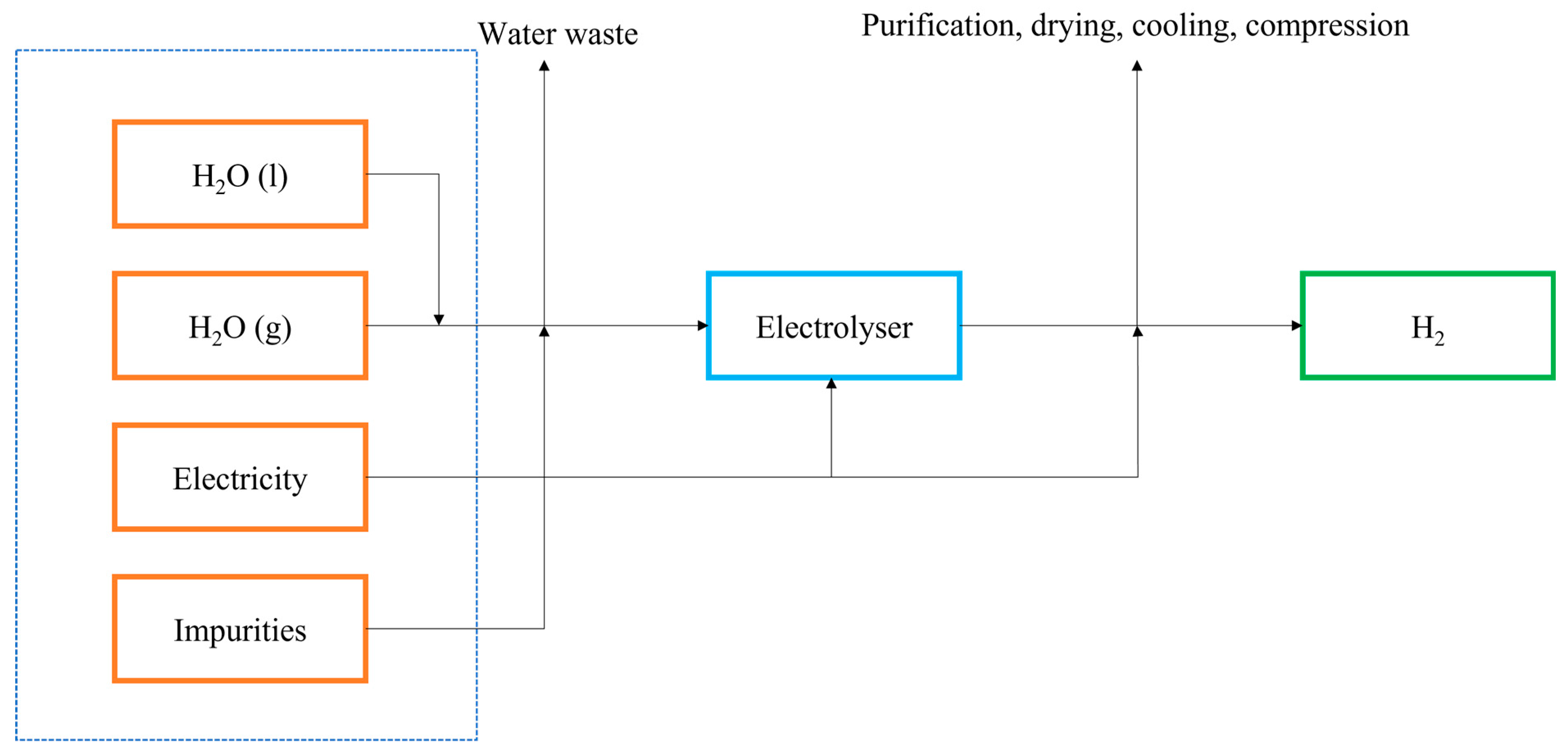
Methane is a colourless, odourless, and highly inflammable compound which is obtained from both renewable (organic matter and animals) and non-renewable sources (coal production and fossil fuels). Steam methane reforming, one of the three hydrocarbon reforming technologies, is the least expensive and most widely used method for producing hydrogen from natural gas [18,19]. Partial oxidation and autothermal reforming are the other two methods used in this technology [20]. Methane makes up a significant portion of natural gas and is one of the major contributors to global warming. Thus, generating hydrogen gas from methane provides a solution for slowing down its accumulation in the atmosphere. The process involves sulphur removal, steam reforming, shift reaction, and pressure swing absorption as captured in Figure 3 [21]. The stages that characterise this process are the mixing of methane with steam under high temperature and pressure in the presence of a catalyst (Equation (1)) and a shift reaction in which carbon dioxide produced in the process undergoes additional reaction with steam to produce more hydrogen gas (Equation (2)). In Ref. [22], the authors mention a temperature range of 700–900 °C and a pressure range of 1.5–3 MPa as favourable for the successful execution of the reaction in Equation (1).
CH 4 +   H 2 O   CO + 3 H 2
CO +   H 2 O   CO 2 + H 2
This is a well-established technology with developed infrastructure and large-scale production capabilities. It is also cost-effective and makes use of natural gas infrastructure. However, this method is heavily dependent on fossil fuels leading to the emission of carbon dioxide into the atmosphere, thus increasing carbon dioxide levels.

2.2. Electrolysis

The ubiquity of water makes it a convenient resource for hydrogen production. Electrolysis is widely used in splitting the molecules of water into hydrogen and oxygen atoms; the dissociation process is given below [24].
Anode :   H 2 O 1 2 O 2 + 2 H + + 2 e
Cathode :   2 H + + 2 e H 2
Overall :   H 2 O H 2 + 1 2 O 2
So far, three major electrolyte systems have been reported in the literature for water electrolysis operating under different conditions using different materials: proton exchange membranes (PEMs) [25,26], alkaline water electrolysis (AWE), and solid oxide electrolysis (SOE). In Ref. [27], the authors mention a hybrid approach incorporating properties of PEM and AWE. The conditions under which these electrolyte systems operate have been summarised in Table 2.
AWE is the most developed of the three systems as the alkaline electrolysers have efficiencies ranging from 50 to 60% at a current density of 100–300 mA·cm−2 [28]. Different electrolytes reported for use in this system are potassium hydroxide (KOH), sodium hydroxide (NaOH), and sodium chloride (NaCl). Two non-platinum group metals, nickel (Ni) and iron (Fe), are used as electrodes in conjunction with the electrolyte and a diaphragm membrane. The diaphragm membrane distinguishes the cathode from the anode and is usually made of asbestos materials (which are currently outdated), limiting the operation temperature. There has been development of new materials to replace asbestos, which include ion inorganic membranes. Moreover, organic polymers, such as polypropylene, can be used in the construction of the diaphragm [29]. Reactions at the anode and cathode are expressed as follows:
Anode :   4 OH O 2 + 2 H 2 O
Cathode :   2 H 2 O + 2 e H 2 + 2 OH
Overall :   H 2 O H 2 + 1 2 O 2
PEM electrolysers, another type of electrolysis device, are used for the production of hydrogen gas [30]. These electrolysers deploy a proton exchange membrane as the electrolyte, an example being NafionTM. Electrolysis using PEM is depicted in Figure 4, where water is split at the anode into proton and oxygen, after which the proton migrates to the cathode where it is reduced to hydrogen gas. The reactions are represented below:
Anode :   2 H 2 O O 2 + 4 H + + 4 e
Cathode :   4 H + + 4 e 2 H 2
Electrolysis through proton exchange membrane (PEM) technology offers distinct advantages, especially when integrated with renewable energy sources. One notable benefit is the rapid response of PEM electrolysers, which allows for quick adjustments to the fluctuating energy output of renewables like solar and wind. This responsiveness ensures efficient utilisation of the available energy, overcoming the intermittency challenge often associated with renewable sources. Moreover, the flexibility of PEM electrolysers enables them to be located in close proximity to renewable energy installations. By situating hydrogen generators near these sources, energy losses during transmission are minimised, enhancing overall efficiency. This proximity also facilitates the creation of localised, decentralised energy systems, promoting energy independence and reducing the need for extensive, centralised infrastructures. These factors underscore the significance of PEM electrolysis in harnessing renewable energy for sustainable hydrogen production, contributing to the advancement of clean and eco-friendly energy solutions [31].
SOE electrolysers have been under development for some time now. Juxtaposed with AWEs and PEMs, these electrolysers can operate at very high temperatures of up to 1000 °C as their efficiency increases with increasing temperatures. They have the lowest specific system energy consumption of 4.5–7.0 kWh/Nm2. The reactions, just like in the previous two at the anode and cathodes, are indicated below [32]:
Anode :   O 2 1 2 O 2 + 2 e
Cathode :   2 H 2 O + 2 e H 2 + O 2
As evident in all three equations, different reactions occur at the anodes and cathodes based on the type of electrolyser used. Using electrolysis, hydrogen can be produced without any direct emissions, and it can incorporate the utilisation of other renewable energy sources: solar, wind, and geothermal, just to name a few. In comparison to other production methods, it requires a significant amount of electricity which may be readily available from non-renewable sources, hence being a double-edged sword. The water and steam electrolysis energy demand is captured in Figure 5. The efficiency of the process is also influenced by energy losses.
Figure 5. Water and steam electrolysis energy demand (Based on information from Ref. [33], with significant modifications).
Cleantechnol 05 00067 g005
Table 2. Working conditions of PEM, AWE, and SOE (Based on information from Ref. [34], with significant modifications).
SpecificationSOEAWEPEM
Cell temperature, °C900–100060–8050–80
System lifetime, yr-20–3010–20
Hydrogen purity, %->99.899.999
Cold start-up time, min>6015<15
Specific system energy consumption, kWh/Nm22.5–3.54.5–7.04.5–7.5
Cell pressure, psi<30<30<30
Current density, A/cm20.3–1.00.2–0.40.6–2.0
Hydrogen production, Nm2/h-<760<30
Stack lifetime, h<40,000<90,000<20,000
Cell voltage, V0.95–1.31.8–2.41.8–2.2
Power density, W/cm2-Up to 1.0Up to 4.4
Voltage efficiency, %81–8662–8267–82
Partial load range, %-20–400–10
Cell area, m2-<4<300

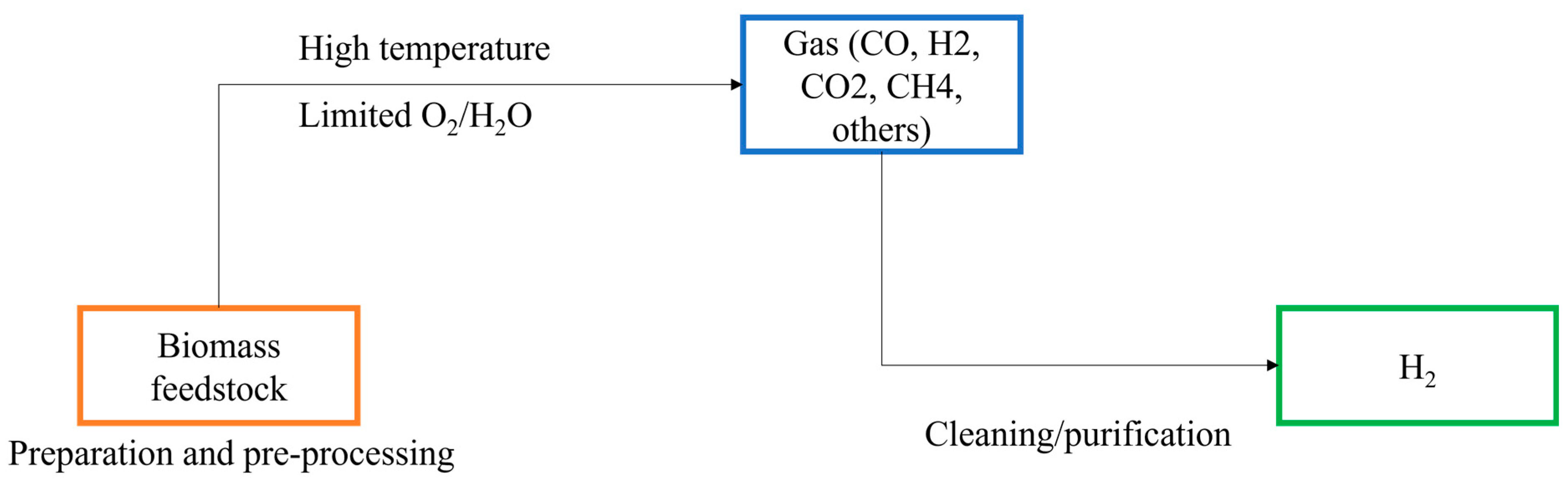
2.3. Biomass Gasification

Gasification can be explained as a thermochemical reaction between an organic substance and a gasifier (oxygen, steam, air, carbon dioxide). Organic matter can be obtained from both renewable and non-renewable sources, such as agricultural waste and coal respectively. Gasification of materials from renewable and non-renewable sources both have different implications for the environment with the latter considered a more sustainable option. This section focuses on the gasification of biomass. Biomass can take various forms: wood and forestry residues, agricultural residues, and algae, to name a few. Biomass gasification involves the conversion of these materials into synthetic gas (syngas). This is a reaction that takes place at high temperatures dictated by a partial oxidation process to release hydrogen, carbon monoxide, methane, and other trace gases [35]. Biomass gasification occurs at a high temperature range of 700–1200 °C [36]. Figure 6 gives a summary of the biomass gasification process.
This process can be integrated with existing biomass or waste processing systems; it can contribute to a more efficient waste management practice. It reduces reliance on non-renewable sources; however, biomass availability can be challenging, and the process can be challenging in terms of control and optimisation. Additionally, incomplete combustion of biomass feedstocks can lead to carbon emissions.

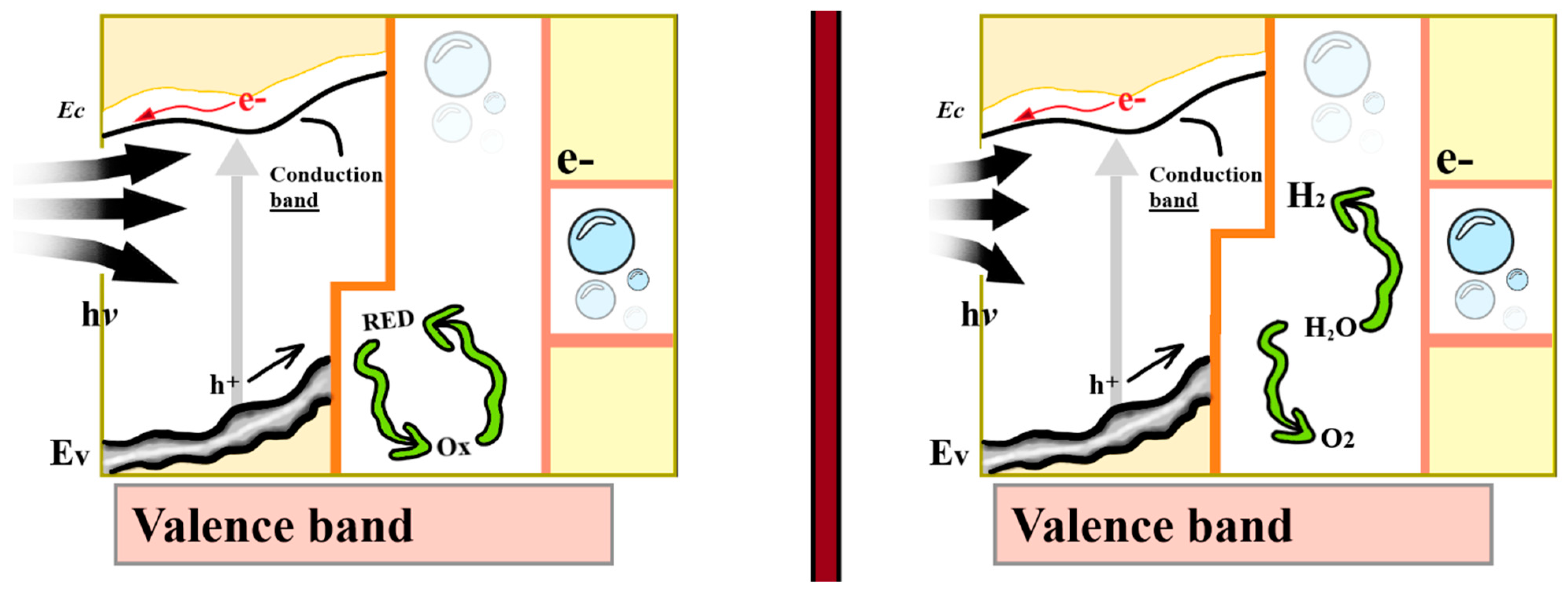
2.4. Photoelectrochemical Water Splitting

Photoelectrochemical water splitting is a way of leveraging sunlight to break water down into hydrogen and oxygen using a semiconductor. The overall reaction process is illustrated below as hv represents an incident photon:
H 2 O h v H 2 + 1 2 O 2
The half equations for the overall reaction are represented by:
H 2 O 2 H + + 1 2 O 2
H + + e 1 2 H 2
A specialised device, a photoelectrochemical cell, consisting of a photoelectrode, and electrolyte, and a counter electrode is used to achieve this purpose. Advantages of producing hydrogen gas using this approach include direct usage of sunlight, which is a renewable resource, and the scalability and suitability of the method. The downsides of this method, however, are evident in its low efficiency, sporadicity of solar energy, and stability challenges for efficient photoelectrodes. One example of this production process using an n-type semiconductor is highlighted in Figure 7 below [37].

2.5. Thermochemical Water Splitting

Thermochemical water splitting, also referred to as thermolysis, involves the decomposition of water into hydrogen and oxygen using heat. It is considered the most environmentally friendly method for producing hydrogen gas with respect to CO2 emissions and acidification potential. It usually involves a series of thermochemical cycles, where materials undergo chemical transformations at high temperatures. The sulphur–iodine chemical cycle is one of the most common cycles used in depicting this thermochemical reaction. It is worth noting that the sulphur–iodine cycle is just one example of a thermochemical water-splitting process. There are other thermochemical cycles with different sets of reactions and operating conditions. It begins with the decomposition of sulphuric acid at 300 °C to 500 °C to release water without a catalyst. SO3 is then separated at 800 °C to 900 °C to produce oxygen, after which sulphuric acid is produced from the next reaction, and finally hydrogen is produced from iodine decomposition [39]. Figure 8 is a pictorial representation of this process. Thermochemical water splitting can be implemented using different diverse heat sources, and it is compatible with the existing infrastructure and industrial processes. Notwithstanding, it has a high temperature requirement, high energy consumption, and comes with complex reaction kinetics.
With respect to ongoing research and developments in the field of the above-mentioned hydrogen methods, current work in SMR focuses on carbon capture and utilisation techniques to mitigate greenhouse gas emissions associated with this process [40,41]. Scientists are exploring advanced materials and catalysts that can enhance the efficiency of carbon capture and storage, making SMR a more environmentally friendly option. Additionally, efforts are directed towards optimising the process parameters and integrating SMR with carbon capture and storage technologies, aiming to reduce the overall environmental impact of hydrogen production from natural gas.
Current research in electrolysis is geared towards improving the efficiency and durability of electrolysers [42,43]. Scientists are exploring novel electrolyte materials for both proton exchange membrane and solid oxide electrolysers, aiming to enhance conductivity and reduce degradation. Moreover, research efforts are focused on developing low-cost, highly efficient catalysts for the hydrogen evolution and oxygen evolution reactions, making electrolysis a more economically viable and sustainable method for hydrogen production, especially when coupled with renewable energy sources [44].
Recent developments in biomass gasification involve advancements in reactor design and gas cleaning technologies. Researchers are working on innovative gasifier designs that enhance the conversion efficiency of biomass into syngas [45,46]. Additionally, efforts are directed towards developing effective methods for removing impurities from the syngas, ensuring the production of high-purity hydrogen. Integrating biomass gasification with carbon capture and storage techniques also holds promise in creating a carbon-negative hydrogen production process, further reducing its environmental impact.
Research in photoelectrochemical water splitting centres around the development of efficient and stable photoelectrodes. Scientists are exploring new materials, such as metal oxides, perovskites, and quantum dots, for use in photoelectrodes to enhance light absorption and charge separation [47,48]. Additionally, efforts are aimed at improving the stability of these materials under harsh electrolytic conditions. Integration with advanced solar cell technologies, such as tandem solar cells, is also a focus, aiming to increase the overall efficiency of photoelectrochemical water splitting and make it a viable option for large-scale hydrogen production powered by solar energy.
Ongoing research in thermochemical water splitting is focused on the development of high-temperature thermochemical cycles that enable efficient water splitting at elevated temperatures. Scientists are investigating various redox materials and reaction pathways to identify thermochemical cycles with high efficiency and low energy input [49]. Furthermore, efforts are directed towards reactor design and heat management systems, aiming to optimise the overall process and reduce heat losses. The integration of renewable heat sources, such as concentrated solar power, into thermochemical water-splitting processes is also a promising area of research, enabling sustainable and efficient hydrogen production through thermochemical pathways [50,51].

3. Environmental Impact of Hydrogen Production Methods

Over the past few decades, there has been a significant increase in the anthropogenic combusting of fossil fuels, which has raised the attention of international researchers regarding the catastrophic repercussions for the environment and human well-being owing to the immediate impact on elevating the release of toxic atmospheric greenhouse pollutants, primarily CO 2 , SO 2 , and H 2 S. Unusual discharges of greenhouse gases into the air are currently raising the risk of a variety of unfavourable events, such as respiratory ailments, climate change, global warming, and crop yield reduction [52].
The annual average temperature of the Earth is expected to rise by 1.25, 2.2, 3.5, and 5.4 degrees Celsius by the end of the years 2025, 2050, 2075, and 2100, respectively, as a result of an increase in the atmospheric carbon dioxide concentration. The production of hydrogen holds immense potential for mitigating the projected temperature rise caused by increasing atmospheric carbon dioxide concentrations. Hydrogen is a clean and versatile energy carrier that when produced using renewable energy sources, such as wind, solar, or hydropower, generates zero greenhouse gas emissions. By shifting our energy systems towards green hydrogen production, we can significantly reduce our reliance on fossil fuels. This transition not only cuts down direct emissions but also curtails the environmental impact associated with extracting and burning traditional fuels, thereby slowing down the pace of global warming. Furthermore, hydrogen can be utilised as an energy storage medium, allowing excess energy generated from renewables during peak times to be stored in the form of hydrogen. When this stored hydrogen is later utilised for power generation or other applications, it reduces the need to rely on fossil fuel-based backup systems, further lowering carbon emissions.
Additionally, hydrogen can play a crucial role in sectors that are challenging to decarbonise, such as heavy industry and transportation. For instance, hydrogen fuel cells can power various modes of transport, including cars, buses, trains, and even ships, emitting only water vapour as a byproduct. In heavy industries, like steel and cement production, hydrogen can replace carbon-intensive processes, helping to significantly decrease emissions. By integrating hydrogen into these sectors, we can pave the way for a more sustainable future, meeting the world’s growing energy demands while simultaneously combating climate change and working towards limiting the temperature rise as projected in the coming years. As a result, identifying and creating new, clean, economical, and safe substitutes for fossil fuels is critical for the long-term sustainability of power supplements. In recent years, the most significant obstacle in the energy industry has been the sustainable fulfilment of the Global Energy Demand (GED) for domestic and commercial operations [53,54].
Global Energy Demand (GED) is the total energy demand of a growing worldwide population and developing economy in areas such as power generation, transportation, industry, and household consumption. Achieving GED is a complicated task that involves a diversity of energy sources, sustainability, and environmental considerations. Because of its adaptability and environmental friendliness, hydrogen energy has attracted attention as a possible option [55]. The main takeaways in GED are highlighted below:
  • Rising Energy Demand: According to the International Energy Agency (IEA), GED is expected to rise by more than 50% by 2040 due to global population growth and industrialisation.
  • Energy sources and sustainability: Fossil fuels dominate the contemporary energy environment, creating challenges such as greenhouse gas emissions, air pollution, and limited supplies. It is critical to transition to more sustainable, cleaner energy sources in order to prevent climate change and protect the environment.
  • Hydrogen energy’s role: Hydrogen is a versatile energy carrier that may be produced from natural gas, water, and biomass via processes such as steam methane reforming and electrolysis. It may be used in a variety of applications, such as car fuel cells, industrial operations, and power generation. Green hydrogen, derived from renewable sources, is a clean, long-term alternative.
  • Managing energy issues: Hydrogen can effectively store and transfer excess renewable energy, acting as an energy buffer to meet peak demand. It also provides a low-carbon alternative for sectors that are difficult to electrify directly, such as heavy industrial and long-distance transportation, by replacing hydrogen fuel cells with fossil fuels.
  • Hydrogen production and costs: The cost of producing hydrogen varies by technique, with steam methane reforming being the most cost-effective but generating carbon without carbon capture and storage. Green hydrogen, created using renewable energy-powered electrolysis, is more expensive but provides environmental advantages, with cost reductions projected as renewable energy becomes more inexpensive.
  • Infrastructure and limitations: Establishing a full hydrogen infrastructure, including production, storage, and delivery, presents considerable hurdles, needing significant expenditures and technological developments.
Many advanced as well as developing nations recognise that the utilisation of hydrogen energy is a suitable means to meet the GED and reduce reliance on renewable energy sources owing to the functional and operational restrictions placed upon the utilisation of fossil fuels across all human-induced activities. Due to its enormous possibilities for use as an environmentally friendly energy source in various commercial approaches, hydrogen has recently gained popularity and has drawn attention on a global scale as an attractive fuel route and energy vector. Because only water and heat vapour are generated during the process of producing it, using hydrogen for energy production greatly decreases the release of greenhouse gases. In those areas where decarbonisation is challenging, hydrogen is viewed as a significant energy source and another option. In recent years, hydrogen has emerged as a promising alternative to fossil fuels, offering potential solutions to mitigate climate change and reduce our reliance on traditional energy sources. One of the key advantages of hydrogen lies in its safety profile when properly handled throughout its production, storage, and utilisation processes. Rigorous advancements in technology and research have significantly enhanced the safety measures associated with hydrogen, addressing concerns related to leakage, combustion, and transportation. Innovations in hydrogen production methods, such as electrolysis powered by renewable energy sources, contribute to its eco-friendliness by minimising greenhouse gas emissions, making it a sustainable option for the future.
In terms of production, advancements in green hydrogen production methods utilising renewable energy sources, like wind and solar power, have substantially reduced the environmental impact of hydrogen generation. These methods eliminate the carbon emissions typically associated with fossil fuel-based production processes, aligning hydrogen production with eco-friendly initiatives. Additionally, stringent safety protocols have been implemented in hydrogen storage and transportation. Cutting-edge materials and engineering techniques are employed to create secure storage systems, minimising the risk of leaks and ensuring safe handling during transit. Furthermore, research has led to the development of robust safety mechanisms in hydrogen-powered applications, including fuel cells and hydrogen combustion engines, ensuring reliable and secure utilisation. These advancements collectively highlight the safety and eco-friendliness of hydrogen as a substitute for fossil fuels, paving the way for a cleaner and more sustainable energy future [56].

3.1. Greenhouse Gas Emissions

Currently, natural gas accounts for a majority of the world’s total production of hydrogen. When H 2 is produced from natural gas with no CCS via SMR, the direct emissions are approximately 9 kg of CO 2 eq per kg of hydrogen [19]. Additional emissions are produced during the natural gas extraction, processing, and transportation processes. These emissions may take the form of methane emissions from leaks or venting, carbon dioxide ( CO 2 ) released from methane flaring at gas fields, or emissions related to the energy employed for the production and delivery of natural gas (for example, emissions related to the electricity used to compress natural gas) [57].
Natural gas midstream and upstream emissions can differ significantly between gas basins and nations, illustrating various production techniques and emission reduction initiatives. The implementation of best practices to reduce emission levels from the production of natural gas, like the ones in Norway, restricts the combined CO 2 and methane emissions to 4.5 kg of CO 2 eq / GJNG , of which 0.8 kg of CO 2 eq / GJNG are methane emissions and 3.7 kg of CO 2 eq / GJNG are CO 2 emissions, primarily from the use of energy during the production of gas and transport. The direct CO 2 emissions produced by burning the natural gas without CCS, which total 56 kg of CO 2 eq / GJNG , are in addition to these midstream and upstream emissions [58].
In other gas-producing locations worldwide, midstream and upstream natural gas supply emissions can be significantly higher, reaching 27 kg of CO 2 eq / GJNG in the Caspian region, for instance (representing roughly fifty percent of the direct emissions of unrestricted natural gas use). Methane emissions from venting and leakages during the production and delivery of gas account for over seventy percent of these midstream and upstream emissions. Currently, gas production results in approximately 15 kg of CO 2 eq / GJNG of midstream and upstream emissions worldwide [23]. When the midstream and upstream emissions are calculated employing this median value, the SMR production path from natural gas with no CCS produces 11 kg of CO 2 eq per kg of hydrogen in total, which is an increase of 2.4 kg of CO 2 eq per kg of hydrogen. The SMR H 2 plant’s direct emissions can be reduced to 0.7 kg of CO 2 eq per kg of hydrogen (capture rate 93%), but the overall emissions rise to 1.5 to 6.2 kg of CO 2 eq per kg of hydrogen when both the lower and upper limits of current global midstream and upstream emissions for natural gas supply are taken into account [59,60,61].
Currently, coal is used to produce about 5% of the world’s H 2 , mostly in China. According to the midstream and upstream emissions for coal processing, mining, and transport, ranging between 6 and 23 kg of CO 2 eq per kg of GJ coal, with a median of 8 kg of CO 2 eq /GJ coal, the production of hydrogen from coal gasification with no CCS results in total emissions of 22 to 26 kg of CO 2 eq per kg of hydrogen. Just under twenty percent of the emissions intensity of coal-based hydrogen production is related to coal processing, mining, and transportation, while more than 80% comes from direct emissions at the production plant. Implementing CCS with an overall capture rate of 93% lowers the coal pathway’s emissions intensity to 2.6 to 6.3 kg of CO 2 eq per kg of hydrogen, a range comparable to natural gas SMR with an overall capture rate of 97% [62].
The upstream and downstream emissions from the production of electricity determine the emissions from water electrolysis. Employing the present average worldwide carbon dioxide intensity of 460 g of CO 2 eq per kW hour leads to an intensity of emissions for H 2 of 24 kg of CO2 eq per kg of hydrogen, which is comparable to the emissions for hydrogen from unaltered coal, though it can be as low as 0.5 kg of CO 2 eq per kg of hydrogen in a nation like Sweden, which currently has one of the least emission variables for electricity from the grid production in the globe (10 g of CO 2 eq per kW hour).
A different source of energy for producing H 2 is nuclear energy. Despite the fact that nuclear power plants have no direct emissions, the enrichment, mining, fabrication, and conversion of nuclear fuel result in emissions of 2.4–6.8 g of CO 2 eq per kW hour. After accounting for these emissions, the total emission intensity for producing H 2 from nuclear electricity ranges from 0.1 to 0.3 kg of CO 2 eq per kg of hydrogen. According to the IPHE procedure, water electrolysers that use renewable electricity have no downstream or direct emissions because these energy sources include hydropower, wind, geothermal, and solar PV. The direct emissions for the production of H 2 from bioenergy are also taken into account as being zero. However, upstream in the supply chains for bioenergy, emissions can happen [63].
These emissions, in the case of employing wood chips, may range from 4 to 18 kg of CO 2 eq per GJ, with overall emissions of 1.0 to 4.7 kg of CO 2 eq per kg for hydrogen from the gasification of biomass. By taking the collected biogenic carbon from the biomass and eliminating it from the natural carbon cycle, such a gasification plant via CCS and an extraction rate of 95%, it produces negative emissions of −16 to −21 kg of CO 2 eq per kg of hydrogen.
Natural gas is employed in SMR as a material for the H 2 molecules and as a fuel to generate steam for the reforming process. Per kg of H 2 generated by an SMR process, approximately 45 kWh of natural gas are needed (kWh per kg of H2). Since splitting the feedstock carbon dioxide from the H 2 is a step in the SMR process, collecting the carbon dioxide from the feedstock-related utilisation of natural gas is feasible at comparatively low capture costs. Using the median upstream and midstream emissions for natural gas supply, this partial capture of the total carbon dioxide emissions yields a total capture rate of sixty percent and emissions of just over six kg of CO 2 eq per kg of hydrogen [64].
For comparison, the emission coefficient for natural gas without upstream emissions is 56 kg of CO 2 per GJ, which is equivalent to seven kg of CO 2 eq per kg of hydrogen. Alternatively, burning hydrogen produced from natural gas using SMR with partial carbon dioxide capture would result in relatively fewer emissions than burning a comparable quantity of natural gas directly in a turbine or boiler, considering a comparable conversion efficiency for both fuels. Hence, in the short term, techniques that enable a slight decrease in the emissions impact of current unrestricted fossil hydrogen production with below seven kg of CO 2 eq per kg of hydrogen can offer emissions advantages, assisting in a decrease in carbon dioxide emissions [19].
Another technology is known as autothermal reforming (ATR), whereby the reformer itself generates the necessary heat. This indicates that the entire production of carbon dioxide occurs inside the reactor. ATR employs oxygen rather than steam and needs electricity as fuel in place of steam. ATR may attain capture rates of 93 to 94% when combined with carbon dioxide capture and needs 47 kWh per kg of hydrogen from natural gas and 3.7 kWh per kg of hydrogen from electricity [19].
The announcement of numerous water electrolyser schemes could result in a worldwide operational capacity of approximately 240 GW by 2030 if the projects are completed. The implementation level is quite similar to what is needed for achieving countries’ APS climate goals. A number of these initiatives employ electricity from dedicated renewable electricity plants directly, while others employ electricity from the grid or a combination of the grid and specially constructed renewable electricity plants [65]. The emissions associated with utilising electricity from directly linked renewable energy sources are presumed to be zero, whereas the emissions associated with electricity from the grid are dependent on the method of generation and fuel mix used within the network as well as how it is run. To achieve low emissions intensities for H 2 when using only grid electricity, the electricity grid must also have a low emissions intensity.
The average global H 2 production emissions intensity currently is 12 to 13 kg of CO2 eq per kg of hydrogen, with the range displaying distinct allocation techniques for byproduct H 2 generated in refineries. The STEPS reduce the average worldwide emissions intensity of the production of H 2 to eleven to thirteen kg of CO 2 eq per kg of hydrogen by 2030 and ten to eleven kg of CO 2 eq per kg of hydrogen by 2050, as shown in Figure 9, owing to decreases in midstream and upstream natural gas supply emissions and the implementation of low-emission technologies for H 2 .
There are emissions sources at each stage or process unit in the hydrogen production process, as shown in Table 3.
Greenhouse gas emissions from electrolysis vary according to the characteristics of the electricity supply for electrolysis since electricity might be acquired from the grid, produced locally through the burning of liquid, solid, and/or gaseous fuels, or provided from an off-grid local system. For SMR with CCS, the main source of GHG emissions is the conversion of natural gas to CO 2 . Other significant emissions sources include the emissions of grid electricity, CO2 compression, and CO2 removal for CCS. The primary driver of greenhouse gas emissions for biomass-based H2 paths with carbon capture and storage is carbon dioxide produced by the gasification methods. Nevertheless, unlike coal gasification or natural gas SMR, CO 2 emissions from biomass gasification are biogenic and do not result in an overall increase in carbon dioxide in the atmosphere. The emissions from grid electricity, energy utilised in the CO 2 elimination process, and energy utilised in CCS are some additional major sources of emissions [67].
The primary source of emissions of greenhouse gases for autothermal reforming with carbon capture and storage is the burning of NG. Leaks of greenhouse gases, the separation of CO 2 and capture, carbon dioxide compression, and CO2 transport for CCS are a few additional major sources of emissions.

3.2. Water Usage

Despite the recognition of hydrogen as a clean and sustainable fuel option, there are valid concerns regarding its impact on water resources during the production process. Water usage is a critical sustainability measure for assessing the production of alternative fuels [68]. Water consumption in hydrogen production varies significantly depending on the specific techniques being employed. Herein, we consider water usage for five (5) H 2 production techniques: steam methane reforming, electrolysis, biomass gasification, photoelectrochemical water splitting, and thermochemical water splitting.
In Ref. [69], the authors indicate that the water requirement associated with hydrogen production exhibits a broad range of 5.7 to 151.4 L per kilogram of hydrogen produced. This measure encompasses the embedded water resulting from electricity usage and encompasses the diverse array of hydrogen production techniques, water treatment methodologies, and cooling choices.
Electrolysis is a fundamental industrial method used in the production of hydrogen. It is also considered a renewable method for producing hydrogen. In this process, water is primarily used as a feedstock, which is split into oxygen and hydrogen using direct current. The estimated future demand for hydrogen is projected to reach 2.3 Gt annually [70]. From a stoichiometric perspective, 9 L of water are needed to produce a kilogram of hydrogen by electrolysis. However, most commercial electrolysis units indicate a water consumption range of 10 to 11 L of deionised water per kilogram of hydrogen produced. It should be noted that additional water may also be necessary for system cooling purposes [71]. Cooling water serves the purpose of indirectly cooling interconnected fluids or equipment, playing a pivotal role in enhancing the efficiency and dependability of plant operations. Water is also used to produce other feedstocks necessary for a hydrogen plant, such as embedded water.
The steam methane reforming process also utilises water as a feedstock. Theoretically, this process requires approximately 4.5 L of water per kilogram of hydrogen produced. However, another source suggests that the water requirement may be around 5.85 L per kilogram. Furthermore, an additional 38 L of water is needed for system cooling per kilogram of hydrogen produced [18].
Table 4 shows the water consumption factors for various hydrogen production techniques as reported by [72]. Typically, the water employed in these processes should possess low levels of dissolved solids, which often necessitates pre-treatment, thereby leading to additional water consumption. To ensure optimal levels of dissolved constituents, cooling water is utilised, resulting in the need for make-up water addition and the discharge of blowdown water.

3.3. Energy and Exergetic Efficiency

3.3.1. Energy Efficiency

According to the US Department of Energy, energy efficiency is simply the use of less energy to perform the same task or produce the same result. Efficient energy utilisation is a key factor in tackling escalating energy demands. Consequently, evaluating the energy efficiency of various hydrogen production technologies becomes essential in order to determine their effectiveness during the production phase [74]. The energy efficiency of a hydrogen production technique can be determined using the following formula:
Ƞ = L H W H 2 Ė i n
where represents the mass flow rate of produced hydrogen, LHV denotes the lower heating value of hydrogen (which is approximately 121 MJ/kg), and Ė i n represents the rate of energy input to the production process.
In terms of energy efficiency, electrolysis demonstrates an efficiency rating of 52%. The electrolysis process requires approximately 200 MJ (55 kWh) of direct current (dc) electricity to produce 1 kg of hydrogen H 2 from 9 kg of water. On the other hand, steam reforming boasts a higher range of 74–85% efficiency [75]. In order to achieve greater efficiency in thermochemical and electrochemical hydrogen production, elevated operating temperatures are required. While water electrolysis is a well-established technology, relying solely on light water-cooled reactors may not render it an energy-efficient, centralised method for future hydrogen production. Conversely, high-temperature steam electrolysis exhibits favourable energy efficiency characteristics.
The energy efficiency ranking for different hydrogen production methods are displayed in Table 5. The ranking scale ranges from 0 to 10, with 0 indicating poor performance and 10 representing the ideal scenario of 100% efficiency.

3.3.2. Exergetic Efficiency

According to the first rule of thermodynamics, energy is conserved. Nevertheless, throughout the transformation procedure, energy cannot entirely be transformed into usable energy. Finding usable energy is an aspect of energy analysis. Exergy is a term for useful energy [76]. Exergy analysis may also determine exergy efficiency, which helps determine the energy system’s ideal rate of energy utilisation. The second principle of thermodynamics may be used to derive the exergy balance relationship without neglecting the work and heat exchange between the system and its surroundings [7,77,78].
Exergy efficiency may be a somewhat more relevant metric than energy efficiency since it provides an in-depth view of performance. Exergy efficiency emphasises the need to assess losses and inherent irreversibility in order to enhance performance. Higher exergy efficiency implies a higher overall energy quality of the system, making it more sustainable, whereas lower exergy efficiencies indicate losses of energy and internal irreversible processes, resulting in less energy quality and a lesser sustainable score [78]. Additionally, exergy analysis identifies energy deterioration in an energy system and offers a precise measurement of the usable work that may be extracted from the system. As a result, the exergy efficiency indicator is a valuable tool for maximising benefit and utilising resources efficiently.
Similarly to energy efficiency, the exergy efficiency score is determined as the ratio of exergy recovered ( Ex out ) to exergy provided ( Ex in ) :
Ƞ = L H W H 2 Ė i n
E x i n = E x f u e l + E x Q      
E x o u t = E x p r o d = n p r o d E x c h , p r o d
E x f u e l = E x r e a c = n r e a c E x c h , r e a c          
E x Q = Q H e a t   ( 1 T 0 T )
where E x f u e l denotes fuel exergy, E x c h   denotes standard mole chemical exergy of pure substances, n i denotes molar flow, and E x Q denotes heat transfer exergy. The chemical exergy of pure compounds is shown in Table 6 [78,79].
The other essential exergy characteristics include unused and destroyed exergy, which are determined using the equations below:
E x D e s t r u c t i o n = E x i n E x o u t    
E x E x h a u s t = E x s u b p r o d = n s u b p r o d E x c h , s u b p r o d                        
E x u n u s e d = E x D e s t r u c t i o n + E x E x h a u s t                          
Exergy destruction is a metric for resource depletion. Even though exergy efficiency analyses the quality of exergy harnessed by the system, the exergy destruction ratio assesses degraded materials and identifies the system aspects where destruction occurs [80,81].
The authors of Ref. [78] conducted exergy studies on various hydrogen production technologies. The efficiency of this exergy analysis is calculated using the following procedure: Exergy analysis can be employed to improve process design by adjusting operating parameters and resources. Any additional heat in the process can be recovered as chemical or thermal energy, thereby increasing the thermal efficiency of the process. Table 7 shows the results of the exergy efficiency calculated using the DWSIM programme. These efficiencies, like thermal efficiencies, are determined by the products in the reactor rather than by the entire process.
The results demonstrate that steam reforming, autothermal reformation, and water electrolysis are the most effective methods for achieving high efficiency in exergy. In contrast, methods like dry reforming or coal gasification of methane have these values approximately 1.6 times smaller. This discrepancy may be attributed to the presence of solid carbon in these processes, which contains a large amount of heat that is wasted without proper optimisation. Additionally, autothermal reforming is a process that relies on the energy content of the reactants, which implies that they will completely utilise the potential energy of the system. Water electrolysis has a significant energy source that is derived from electricity with a low degree of energy destruction. Natural gas pyrolysis exhibits a lower degree of exergy than other more popular processes, like the steam reforming of methane. However, methane’s pyrolysis has the highest percentage of wasted energy as a result of the byproduct (solid carbon). As previously stated, the exergy connected to this parameter ( E x E x h a u s t ) is the sole one that may potentially be recovered, raising the exergy efficiency of the operation by doubling its value (80%). In reality, solid carbon is a product that may be effectively utilised within the framework of a sustainable economy [78].

3.4. Air Pollution

To reduce emissions in the transportation industry, hydrogen has been used on an increasing basis in the United States as a clean fuel alternative for vehicles like fuel cell electric vehicles (FCEVs) (see Table 8). Currently, transportation is a significant source of air pollutants, contributing to over 50% of the nation’s emissions of nitrogen oxides (NOx), over 30% of volatile organic compounds (VOCs), and more than 20% of particulate matter (PM). The atmospheric chemistry implications of a hydrogen-based energy system remain uncertain. While the utilisation of hydrogen in clean fuel cells effectively eliminates the emission of air pollutants like sulphur dioxide (SO2) and nitrogen oxides (NOx) during the end-use phase, there is still the possibility of air pollutant emissions during the production of hydrogen [82]. Hydrogen is considered to have great potential for being a viable energy resource for green aviation in the mid to long term [83].
A study conducted by [28] looked at pollution emissions from thirty-three (33) SMR hydrogen production facilities. They discovered that emissions from these hydrogen production facilities had very high CO and NOx levels, while other emissions sources were comparatively insignificant [28]. Due to the inability to eliminate emissions from SMR hydrogen production (known as grey hydrogen) facilities, the adoption of hydrogen production utilising carbon capture and storage (referred to as blue hydrogen) has emerged as a viable approach to reduce overall emissions from the production process. Another study compared emissions of air pollutants across three hydrogen production methods: steam methane reforming, biomass gasification, and coal gasification. Their analysis showed that SMR led to lower emissions of air pollutants excluding CO and NOx when compared to biomass and coal gasification [82].
Additionally, another research study established a connection between gasification and the generation of acid rain by attributing it to the production of sulphur oxides, which are formed as a result of coal’s sulphur content. Regarding coal gasification, a diverse range of values was reported for NOx and CO emissions, with NOx levels comparable to those of SMR, while CO emissions potentially reached much higher levels [82]. Limited information is available on air pollutant emissions in various hydrogen production chains. Most studies primarily examine the impact of hydrogen-based systems on greenhouse gas emissions, overlooking the effects on atmospheric pollutants.

3.5. Land Use

According to [37], land use refers to the extent of land area needed for the production or storage of hydrogen, measured as m2 land requirement/kg of hydrogen [37]. One study conducted an analysis of performance indicators associated with some important hydrogen production systems. One of the performance indicators was environmental performance criteria, composed of elements like greenhouse gas emissions (GHG), water discharge quality, land use, and solid waste, which were considered to enhance comprehension of their actual environmental impact. Comparing environmental criteria, GHG emissions hold the highest priority, while land use was the least significant. Land use has the lowest priority compared to air and water quality impacts [84].
SMR uses natural gas as its main raw material, so it does not need much land. Nevertheless, the production and delivery of natural gas may have effects on the land, such as destroying habitats, causing deforestation, and possibly contaminating groundwater [28].
The type of electricity used for electrolysis has a significant impact on how land is used. The land use needed for electrolysis is very low when using renewable energy sources, like wind or solar power. But if electricity is produced using fossil fuels, such as natural gas or coal, the effects on land use (such as mining operations and power plants) should be taken into account [24].
Since biomass gasification depends on growing biomass crops, it may necessitate extensive land use. Large tracts of land may be required for the use of agricultural residues or the cultivation of specific energy crops, according to the scale of production. Inadequate management of biomass production can result in forest clearing, habitat loss, and contention with food production, all of which have an adverse impact on the environment [85].
PEC water splitting that utilises solar energy as its power source usually requires minimal land use specifications. On the other hand, the facilities needed for large-scale deployment, like solar panels or other equipment, could take up land. To lessen any possible effects, good siting and land management techniques should be taken into account.
The utilisation of wind power and photovoltaic (PV) cells for hydrogen production exerts a substantial influence on land utilisation. These facilities are often situated at considerable distances from densely populated regions, primarily owing to the extensive land requirements inherent to both technologies. However, it is worth noting that the expenses associated with transmitting the energy generated can escalate significantly [86]. Biological methods for producing H 2 , including the process of fermentation or the photosynthesis process employing algae or microorganisms, may need different amounts of land based on the technique and scale. In order to grow and contain algae or microorganisms for the production of H 2 , H 2 O or land surface areas may be needed. The cultivation methods used and possible rivalry with other land uses play a significant role in the environmental effects of biological H 2 production on the land [85].
It is significant to remember that the environmental effects of land use extend beyond the actual area used. Land-use choices made during the H 2 production process can also have an effect on variables like biodiversity loss, soil degradation, deforestation, and water resource effects.
Every phase of the life cycle of H 2 production, from the production of feedstock to its production and distribution, must be taken into account in order to guarantee its sustainability. Utilising marginal or degraded land, employing sustainable agricultural methods, and giving renewable energy sources priority are some actions that can be taken to lessen the effects of land use on the environment.

4. Comparative Analysis of Hydrogen Production Methods

4.1. Comparison of Environmental Impact

The main indicators employed in life cycle evaluations of environmental impacts include acidification potential (AP) [87], global warming potential (GWP) [52], abiotic depletion potential (ADP) [52], human toxicity potential (HTP) [87], and eutrophication potential (EP) [61]. In this study, we concentrate mainly on GWP because it represents greenhouse gas emissions during the hydrogen production process, which is a major environmental concern. In addition, we consider ADP (fossil) and AP to account for the consumption of fossil fuel and acid substance emissions resources, respectively.
It is important to note that different sources of literature present different values for these indicators, particularly for H 2 production using clean energy sources. This variation could be attributed to difficulties in acquiring standardised parameters for techniques that have yet to be widely adopted on large scales. As a result, the inventory data utilised in evaluation may differ, or further self-defined parameters may be necessary. To address this, instead of a single value, we will provide the minimum, average, and maximum results to encompass the range of possible outcomes. The data pertaining to various H 2 production methods is presented in Table 9. However, it should be noted that certain technologies, like microbial H 2 production, are currently restricted to laboratory research and lack comprehensive life cycle assessment data. Consequently, this table does not encompass the entire spectrum of available H 2 production methods.
The global warming potential (GWP) [52] and acidification potential (AP) of various H 2 [87] production methods have been assessed, considering average, maximum, and minimum values. These indicators provide insights into the environmental impacts associated with different H2 production processes, encompassing the range of potential outcomes. By evaluating GWP and AP, we can better understand the greenhouse gas emissions and acidifying substance releases associated with each method, aiding in decision-making for sustainable H 2 production.
Due to their extremely high AP and GWP amounts, fossil fuel-based techniques, such as CG and the reforming of specific fuels, are thought to have the most detrimental effects on the planet. Particularly, electrolysis derived from grid electrolysis has the lowest GWP of all the methods for producing H 2 , with CG having the second highest at 22.99 kg of CO 2 eq. As the outcome demonstrates, applying carbon capture and storage (CCS) methods to the process of producing H 2 from fossil fuels can significantly reduce GHG emissions. According to estimates, CCS incorporation can cut the GWP of CG by 71.8% to 71.7%. The average rate of GWP has decreased by 69.1% for SMR. The precise impact is determined by how well CO 2 is captured. The promotion of CCS technology, however, has not focused on real-world uses.
The ADP of H 2 production from fossil fuels is another crucial metric as these fuels not only serve as an alternative energy source but also as a source of H 2 atoms, indicating higher consumption. SMR is a more energy-efficient option because the main energy use estimates in the scientific literature place it between 183.2 and 198.4 MJ [95] and 213.8 and 333.2 MJ for CG respectively. ADP values for alternative methods are lower due to the fact that they do not use fossil fuels as raw materials. As a result, when evaluating new energy technologies, AP and GWP are frequently prioritised over ADP. We are unable to conduct more comprehensive comparisons because of the consequent absence of information depth in ADP.
A mixture of AP and GWP is produced by biomass gasification. This has a bigger environmental impact compared to thermochemical and electrolysis cycles based on new energy sources but fewer consequences than methods based on fossil fuels. In light of the state of the art, biomass gasification presents a different option while switching from fossil fuels to water as a H 2 source [36].
The primary factor affecting the GWP of the hydrolysis process is the electrical energy source, which may significantly impact the outcomes [6]. In the event that grid electricity is employed in accordance with the current electricity system, an extremely significant environmental impact occurs, exceeding even CG (59.7 g of SO 2 eq, 22.99 kg of CO 2 eq) and SMR (15.2 g of SO 2 eq, 11.98 kg of CO 2 eq) with an AP of 69.0 g of SO 2 eq and a GWP of 29.21 kg of CO 2 eq, respectively. AP and GWP decrease substantially if the electricity is produced using renewable energy sources, like solar, wind, or nuclear power. As a result, it is crucial to couple electrolysis systems with clean electricity.

4.2. Comparison of Energy Efficiency

The vast majority of commercial H 2 produced globally today is produced using the SMR technique, which is currently among the most popular techniques. Hydrogen and CO2 are byproducts of the SMR process, which involves the reaction of natural gas (methane) with steam. SMR is a well-established and economical process, but because methane has a high carbon content, it does not use a lot of energy. When taking into account all aspects of the production procedure, such as transportation, extraction, and conversion of methane, SMR usually has a total energy efficiency of 65–75% [95].
The molecules of water are split into O 2 and H 2 through a process called electrolysis. The main benefit of electrolysis is that its sole byproducts are O 2 and H 2 , making it an environmentally friendly method. But the type of electricity that is used for the electrolysis process determines how energy-efficient it is. Electrolysis is capable of achieving high energy efficiencies of between 70 and 80% when using renewable energy sources, like wind power or solar. On the contrary, the total energy efficiency can be substantially lower, usually between 50 and 60 percent, if the electricity is generated by grids that rely on fossil fuels [95].
In the process of biomass gasification, organic materials, like wood or agricultural waste, are transformed into a blend of H 2 , CO, and CO 2 . The syngas gas mixture can then undergo additional processing to yield pure H 2 . A renewable and carbon-free way to produce H 2 is through biomass gasification. The particular gasification technology, feedstock, and subsequent purification procedures all affect the total energy efficiency. The energy efficiency of biomass gasification for the creation of H 2 varies between 40 and 60 percent on average, with some cutting-edge systems achieving efficiencies that are close to 70 percent [95].
It is important to note that the energy efficiency information given above is an approximation and may change based on a number of variables, including the particular methods used, process optimisation, and the incorporation of the total energy system. Furthermore, attempts to enhance the energy efficiency of H 2 production processes are being made as a result of continuing study and advances in technology.
Overall, SMR is presently the most popular technique for producing H 2 , but because it depends on methane, it is not very energy-efficient. Greater energy efficiencies can be attained through electrolysis, particularly if it operates on sources of renewable energy. In comparison to electrolysis and SMR, biomass gasification provides a renewable and carbon-free method but usually has fewer energy efficiencies. Enhancing energy efficiency is still a top priority as methods for producing H 2 are developed in order to assure long-term, economical H 2 production.

4.3. Comparison of Economic Viability

The cost of producing, utilising, and transporting H 2 , as well as storing it, can all be used to evaluate the economics of H 2 energy systems. The cost of primary energy sources determines how important H 2 production is right now within these factors. The cost of newly developed H 2 production methods based on renewable energy is currently higher than those based on fossil fuels when taking economic factors into account. Electricity prices have an impact on how much it costs to produce H 2 from non-fossil sources of energy [35]. Electrolysis is the most popular technique for generating hydrogen from non-fossil fuel sources, but the price of the electrolyser and how it is used affects the cost of electrolysis. Due to the lack of CO 2 , electrolysis produces H 2 at a price that is competitive with alternative techniques, resulting in the production of green electricity. In line with this, the price of fossil fuels determines how much H 2 can be produced. For instance, from a comparative standpoint, pressure swing absorption, H 2 purification techniques, and catalyst costs are among the most significant barriers to thermochemical techniques. These factors all raise the price of H 2 production while lowering biomass costs and improving efficiency.
Economically speaking, the water electrolysis process is a viable option for small-sized H 2 production; however, because of the high electricity usage in the production of large quantities, the price of the electrolyser rises to about 5% [23]. The cost of producing H 2 using photochemical and dark fermentative techniques was predicted to be between USD 2.8 and 2.5 per kg [17]. According to [96]’s estimates from 2017, the costs of producing H 2 using the photo and dark fermentative processes were about USD 18.70 and 3.70, respectively. Recently, it was reported that the price of H 2 in Australia ranges from AUD 1.88 to 2.30/kg of H 2 for the production of steam methane reforming and from AUD 2.02 to 2.47/kg of H 2 for the production of coal gasification, respectively. Alkaline electrolysis costs AUD 4.78 to 5.84 per kg of H 2 , while proton exchange membranes cost AUD 6.08 to 7.43 per kg of H 2 , according to electrolysis techniques.
The cost to produce partial methane oxidation using synthesis gas is EUR 1.33/kg of H 2 [73]. In Ref. [97], the authors reported in further research that the production of H 2 from natural gas and coal costs USD 0.37 to 1.82 per kg and USD 2.48 to 3.15 per kg, respectively. Even though the cost of wind and solar energy was found to be high from 2011 to 2016, with an annual growth rate of up to 5.6%, it was determined that the H 2 market would increase by 6.21% from USD 87.3 to 118 billion from 2011 to 2016. According to [98], biomass gasification and pyrolysis will produce H 2 at prices between USD 8.91 and 5.51 per GJ and USD 10 to 14 per GJ, respectively, making the SMR process a cost-effective and advantageous method for producing the gas.
Table 10 shows the costs of various H 2 production technology. Steam methane reforming is significantly less expensive (USD 0.75 per kg) compared to the other techniques for producing H 2 [99]. Solar electrolysis currently has the costliest method of producing H 2 (USD 5.0/kg); nevertheless, with technological advancements, the cost can be reduced, and it may be the most advantageous method sooner or later from a sustainability perspective. As a result, commercialisation of these methods is expected to occur over time, and due to their insignificant impact on the environment, the cost of producing H 2 is expected to be less than or equivalent to that of traditional techniques employing fossil fuels.

4.4. Comparison of Technological Maturity

Table 11 underlines the comparison of various hydrogen-producing technologies’ development levels, the feedstocks, manufacturing techniques, efficiency, and temperature.
The amount of low-emission H 2 currently produced and the amount that is required to have the world be on top with the NZE and the APS scenarios are remarkably far apart. The development of significant capacities for the production of low-emission H 2 , however, has been the goal of a significant number of projects that have been declared. By 2030, 24 Mt of low-emission H 2 might be produced annually, assuming that all projects that have been declared are completed (Figure 10). Even though these projects are distributed across the world, approximately fifty percent of the production that might be attained from all of them would come from G7 members.
A quarter of the low-emission H 2 needed for the NZEs by the 2050 scenario would be met by the projects that have already been declared, but only 80 percent of the APS needs. Unpredictability exists regarding the number of projects that have been announced that will be functional by 2030. Most of these projects will not be achieved under the present regulatory landscape because of deployment challenges that project developers are currently facing, such as a shortage of demand, unpredictability about regulation and accreditation, and a lack of facilities for delivering H 2 to final consumers. Additionally, developing nations (which make up about a quarter of what could be produced from APs) face significant, additional obstacles, such as the requirement to train qualified workers and challenges in gaining financial assistance. Deployment will be restricted to 6 Mt, as predicted in the STEPS, without adequate policy measures being taken to remove these obstacles.
The degree of maturity of the projects currently being developed can give an accurate picture of whether it will be possible to realise their full potential for production by 2030. About four percent of the projects are presently in advanced phases of development, meaning they are being built or have made a final investment decision (FID), measured by the amount of output they produce in 2030. Approximately one-third of the possible generation of low-emission H 2 falls into projects at the concept stage, which means they are in the earliest phases of their development, while the remainder comprises projects going through feasibility analysis and engineering assessments.
Approximately two percent of the CCUS projects are nearing completion, corresponding to 0.2 Mt of low-emission H 2 being produced by 2030. About five percent of electrolysis projects are in advanced development (which corresponds to about 0.7 Mt of low-emission H 2 generation), with the majority of the possible output resulting from projects going through feasibility analysis and engineering assessments (fifty-eight percent of possible production) or in the planning stage (thirty-seven percent of prospective production). This implies that a large number of projects are still a long way from completion. The building process and installation of H 2 projects can take anytime from a couple of years (in the states of electrolysis projects less than 100 MW) to a decade (for larger CCUS projects).
Over eighty percent of the H 2 produced in 2021 by G7 members came from functional CCUS projects utilising fossil fuels, and forty percent came from functional electrolysis projects. Approximately 0.5 Mt of prospective low-emission H 2 production is additionally found in G7 participants, where almost fifty percent of the announced projects that are currently being built or have received an FID and may be functional by 2030 are located. Furthermore, feasibility analyses and engineering assessments are being conducted on projects in G7 nations that could produce 8.5 Mt of low-emission H 2 by 2030. As 55% of all projects worldwide are in this phase of development, the G7 has a major role to play in rapidly developing the production of low-emission H 2 [21].

5. The Influence of Hydrogen Safety on the Economy of Hydrogen Energy

Even though the H2 economy has a promising future, there are certain H2 safety concerns that must not be overlooked. Though H2 is harmless and free of contaminants [102], it is very combustible and has a substantially greater flame propagation rate than other fuels [103]. When compared to other fuels of the same volume, H2 burns away in 10 to 20% of the time [99]. The H2 economy consists of the H2 generation, storage, distribution, and utilisation processes. Reliable safety precautions are required in all phases of hydrogen generation, storage, transit, and utilisation, which raises the overall price of the H2 economy.

5.1. The H2 Economy

John Bockris initially introduced the H2 economy as an idea in 1972 [104]. A H2 economy is a system in which H2 gas is employed as the primary energy carrier for power production, transportation, and industrial activities. It aspires to substitute fossil fuels with H2 that can be generated and utilised in a sustainable and environmentally friendly manner. With the depletion of fossil fuels and the major environmental pollution concerns created by the large-scale usage of fossil fuels, the search for a novel clean energy carrier has become increasingly crucial. In comparison to the present direct consumption of power generated by tidal, wind, and nuclear energy, given its inexhaustible availability and non-toxic properties, H2 is expected to become an essential or perhaps major energy carrier in years to come [99]. Although the costs of H2 production, delivery, and storage are now considerable, its vast possibilities and benefits continue to draw international interest. Governments around the globe have also emphasised the relevance of the hydrogen economy [105]. However, one significant benefit of the H2 economy is the fact that it may attain zero carbon dioxide emissions along the full H2 energy industrial chain, and numerous nations have begun charging carbon dioxide emissions [106]. The United States Department of Energy established a five-year objective for H2 storage and H2 fuel cell research in 2003 [107]. Simultaneously, the European Commission’s High-Level Group on Fuel Cell and H2 Technology suggested that the EU establish a H2 economy by 2050, with 35% of newly built automobiles powered by hydrogen by 2040 [108]. In the meantime, in 2002, the Brazilian Ministry of Science, Technology, and Innovation established the Brazilian Fuel Cell and H2 System Programme. In 2005, this programme changed its name to the H2 Economy Science, Technology, and Innovation Programme to encourage the advancement of H2-based technologies and fuel-cell technology in Brazil [109].

5.2. Hydrogen Storage

Lately, the absence of cost-effective, reliable H2 energy storage systems has been identified as a major impediment that must be solved as soon as possible. Despite its incredibly low density and considerable flammability, H2 is chemically stable and may be kept in stable circumstances for a long period of time. Based on their phase condition, H2 storage systems are classified as solid, gaseous, or liquid [104].
As H2 has a known extremely low density (0.089 kg/m3), its volumetric energy density is low. Therefore, in order to store H2 efficiently, high pressure or very low temperatures are needed. Right now, storing gaseous H2 in high-pressure containers, such as those rated at 35 MPa or 70 MPa, is the most used and developed technique of storing it [110]. Leakage of H2 from steel or aluminium cylinders under high-pressure storage settings is a possibility. In the event of an accident or discharge, there might be a risk to public safety if electrical sparks are produced. A plastic composite tank reinforced with carbon fibre offers greater durability and impact resistance than a metal H2 storage tank, which can help lower safety hazards. However, the final cost of using H2 will rise as a result of its expensive price [104]. Natural salt caverns are a better high-pressure gaseous H2 storage option than constructed hydrogen storage tanks when it comes to economics. Natural basement geological formations may store H2 at higher pressures and volumes with minimal effects on the environment or public safety. Though one H2 molecule consists of only two H2 atoms, the energy density per volume of H2 is only one-third that of natural gas, making its storage costlier as well as less effective [111]. The operational conditions of high-pressure gaseous H2 storage are comparable to those of natural gas storage. Furthermore, compared to natural gas, there is a higher chance of H2 leakage. Given the tiny size and high diffusivity of H2 molecules, it is imperative to ensure the appropriate selection and construction of the salt cavern. Construction and design should also take soil and steel sealing into account [111].
Hydrogen embrittlement is another important aspect of gaseous H2 storage. After prolonged exposure to H2, metal materials undergo embrittlement. When temperature and concentration gradients induce hydrogen atoms to diffuse via metal, they recombine to create H2 molecules in the metal gaps, which raises the pressure inside the metal cavity and causes the phenomenon. As H2 molecules build up, the pressure progressively rises until the metal substance splits and becomes brittle. Including alloying elements like nickel and molybdenum to boost H2 permeation resistance, adjusting process parameters like annealing temperature or electroplating conditions, and using corrosion inhibitors to lower the corrosion rate are some ways to avoid H2 embrittlement [112]. Without a doubt, this will result in higher process costs, material expenses, or unanticipated, new safety concerns.
Another method of physically storing H2 is liquid H2 storage. Liquid H2 has a density of 71 g/L at its boiling point of 20 K, but compressed H2 has a maximum density of 30 g/L at ambient temperature. The liquid H2 storage tank has a far higher density and a much lower internal pressure as compared to high-pressure gaseous H2 storage. Since H2 must be maintained at a low temperature of 20 K in a tank with good thermal insulation and the liquefaction process uses significant quantities of energy, roughly 30% of the H2’s energy content [112], liquid H2 storage has higher efficiency for both transportation and storage, but it also comes at a higher cost in terms of equipment and energy consumption. In general, the price of liquid H2 storage is approximately four to five times that of gaseous H2 storage [14].
The advancement of the H2 economy necessitates the construction of a robust H2 storage facility with satisfactory levels of safety, economy, effectiveness, and ease. Because it is safer and more stable than gaseous or liquid H2 storage, H2 storage in either liquid or solid materials is gaining popularity [104]. By absorbing solid materials and releasing them under optimum pressure and heat conditions, H2 molecules may be kept securely and persistently. There are two types of solid H2 storage: physical and chemical adsorption. Physical adsorption employs van der Waals force to adsorb H2 molecules in materials such as carbon fibre tubes and other porous structures, which are subsequently released at a suitable temperature [16,113,114]. Although this technology is reversible and has a low storage cost, its H2 storage capacity is often limited. The H2 storage potential of alkali metal-modified carbon nanomaterials, for instance, ranges from 8 to 9 weight percent [115], making them inadequate for large-scale H2 storage and, hence, severely limiting their practical applicability. Chemical adsorption employs metal hydride and H2-containing organic matter (carbohydrate, formic acid) to store H2 via hydrolysis and emit it via catalytic pyrolysis. Chemical production of hydride has a greater energy density and a milder operating condition than physical adsorption. The storage of H2 by sodium borohydride, lithium aluminium hydride, and borane ammonia is safer and has a greater storage density, which can be over 10 percent. However, the emission of H2 from metal hydrides is typically irreversible and comes with byproducts. Because the interaction of hydrides with water causes a strong hydrolysis process, the ambient humidity for their storage is severely limited [116]. Furthermore, the expensive nature of metal hydride compounds raises the price of H2 storage. Though metal hydrides are regarded as among the most practical hydrogen storage solutions [117], more work has to be carried out in regard to reaction kinetics, material prices, storage period, and conditions of reaction.

5.3. Hydrogen Transportation

There are three basic means of transporting H2: liquid H2 via ship, truck, and rail; gaseous H2 by pipeline; and absorbed H2 via various materials. As previously stated, the biggest safety risks with the latter two procedures are linked to their storage. The gas pipeline transportation facility is linked to the safety concern.
Transporting H2 by pipeline is a safe method, particularly when the pipeline has a small diameter and low pressure. It is perfect for transporting huge amounts of H2 across long distances. However, building the pipeline network requires a significant financial outlay, and a unique coating treatment is further necessary to stop H2 from penetrating and causing embrittlement issues for the pipeline. Because of its very low density and quick diffusion rate, H2 poses a danger of leakage along the pipeline. Although H2 has no taste or smell, it is not appropriate to add an odourant to it in order to detect leaks, as this will contaminate the H2 gas and impact its final application [14].

5.4. Safety Concerns with the Transportation and Storage of Hydrogen

Material degradation during H2 storage and transit will result in pipe and tank damage. The H2 molecule will infiltrate the metal under high pressure, damaging the inner structure of the metal and causing mishaps during storage and transit. There are basically three forms of material degradation caused by H2: H2-induced cracking, H2 embrittlement, and high-temperature H2 corrosion, with H2 embrittlement being the most prevalent [118].
Pressure vessels made of carbon fibre composite for the outside packing and a polymer sealing lining are commonly used as H2 tanks. When the depressurisation rate is greater than the rate at which the absorbed gas escapes by diffusion, H2 will be absorbed by the plastic liner at high pressure, causing blistering of the liner [56]. In the event of a failure, the composite material bearing the principal pressure load may split as a consequence of the blistering of the liner in the H2 storage tank. This might cause serious mishaps.
The materials employed in liquid H2 structures are subjected to low temperatures; thus, when choosing materials for these types of structures, particular attention should be paid to the change in material characteristics. In low-temperature H2 usage, low-temperature thermal shrinkage and low-temperature embrittlement are the most significant thermal characteristics. A reduced ability to absorb impact energy in a material at lower temperatures is known as low-temperature embrittlement. A material’s ability to absorb impact energy is greatly diminished, and it transitions from a ductile to a brittle state when its temperature falls below the critical transition temperature for toughness and brittleness. Because thermoplastic materials naturally expand at low temperatures, the process known as “low-temperature thermal contraction” describes how the volume of these materials contracts [119].
When the system’s temperature approaches 200 °C, the metal will come into contact with H2 at high pressure and temperature. Hydrogen molecules or hydrogen atoms can readily infiltrate the metal in such an atmosphere. When penetrating H2 molecules or H2 atoms interact with the metal’s impurity elements, gaseous products are frequently generated, and high-temperature H2 corrosion occurs. Because of the tiny size of H2 atoms, H2 dissolved in metals has great fluidity. Hydrogen atoms dissolved in the metal can recombine to generate H2 molecules, which can then mix with carbon to form methane within the metal’s microstructural defect holes. The production of methane gas can result in high internal pressure, resulting in the creation of bulges and fissures inside the metal. As a result, high-temperature H2 corrosion may be exacerbated [120].
During the storage and transportation of hydrogen, it is possible for it to leak and disperse. Hydrogen has a low ignition point and can explode into flames quickly. Even without a fire, H2 leaking is a dangerous circumstance, especially in tight places where it can induce asphyxiation. When low-temperature liquid hydrogen (LH2) is released into the atmosphere, it evaporates violently, forming a high-concentration H2 cloud that spreads over a vast area and causes combustion or even explosion if a spark occurs. To simulate LH2 leakage, [121] developed a pseudo-source model and utilised the commercial CFD application FLACS. This study examined the effects of liquid hydrogen refuelling station (LHRS) layout, leakage factors, and local climatic variables on the repercussions of LH2 leakage. It has been discovered that the caravan parking site in the present LHRS layout would exacerbate the explosive implications of the LH2 leak. More importantly, when the leaking equivalent width is 25.4 mm, an explosion might occur, inflicting terrible harm on nearby people. According to the data, the chance of an explosion diminishes as wind speed increases [121].

6. Conclusions and Recommendations

A thorough evaluation of the different hydrogen production techniques and their effects on the environment has been given in the present paper. When evaluating the efficacy of various hydrogen production techniques, the findings highlight the significance of taking the effects on the environment into account in addition to technical viability. It is obvious that no particular strategy can be regarded as the best one because each approach has pros and cons in terms of performance, scalability, affordability, and adverse environmental effects.
Steam methane reforming generates a substantial quantity of carbon emissions regardless of its cost-effectiveness and high rate of production, underscoring the requirement for technologies to capture and store carbon in order to lessen its negative environmental effects. Although electrolysis appears to be a viable renewable hydrogen production technique, more research is needed to lower the amount of energy needed and increase its economic viability. SMR is now the most used process for creating methane; however, because it relies on methane, it is inefficient in terms of energy. Electrolysis can achieve higher energy efficiency, especially when using renewable energy sources. In comparison to electrolysis and SMR, biomass gasification is a green and carbon-free process; however, it often has lower energy efficiency. Improving energy efficiency is a primary focus as new manufacturing methods are developed to ensure long-term, cost-effective output.
The environmental sustainability of hydrogen production can be substantially enhanced by including renewable energy sources, like solar and wind power, in the processes. The carbon impact of hydrogen can be significantly decreased by using renewable electricity for electrolysis or simply powering biomass gasification.
The following suggestions can be made to promote the creation and application of environmentally friendly hydrogen technology in light of the review’s findings:
  • Research and development: To increase the effectiveness and environmental sustainability of hydrogen production techniques, more research and development are required. To circumvent their present restrictions and improve their economic viability, emphasis should be placed on thermochemical, biomass gasification, and electrolysis methods.
  • Integration of renewable energy sources: Regulations and financial incentives ought to be put in place to promote the incorporation of renewable energy sources, such as solar and wind power, into the methodologies used to produce hydrogen. As a result, carbon dioxide emissions linked to the production of hydrogen will be decreased, and the overall sustainability of the energy system will be improved.
  • Technological innovation: For the advancement of hydrogen production techniques, investments in new technologies and pilot initiatives are crucial. Partnerships between governments, businesses, and academia can hasten the creation of new, environmentally friendly methods for producing hydrogen.
  • Life cycle evaluation: Performing thorough life cycle analyses of various hydrogen production techniques can give us in-depth knowledge of the effects they have on the environment. To discover and tackle prospective environmental hotspots, this assessment should take into account every step, from the extraction of raw materials to the final product.
  • Policy encouragement: To encourage the implementation of environmentally friendly hydrogen production methods, policymakers and governments ought to develop enabling policies, rules, and rewards. To encourage the switch to more environmentally friendly hydrogen production techniques, this involves pricing carbon processes, funding for research, and tax incentives.
These suggestions can be put into practice in order to pave the way for a hydrogen economy that is more environmentally friendly, aiding efforts to reduce global warming and create an energy system that is more sustainable.

Author Contributions

Conceptualisation: S.G.N., C.K.D. and P.C.O.; investigation: S.G.N., C.K.D., P.C.O., X.S. and B.K.; methodology: S.G.N., C.K.D., P.C.O., B.K., X.S. and K.J.; supervision: B.K., X.S. and K.J.; writing—original draft: S.G.N., C.K.D. and P.C.O.; writing—review and editing: S.G.N., C.K.D., P.C.O., B.K., X.S. and K.J. All authors have read and agreed to the published version of the manuscript.

Funding

The authors would like to thank Cranfield University and Sion Group Ltd. for their financial support.

Institutional Review Board Statement

Not applicable.

Informed Consent Statement

Not applicable.

Data Availability Statement

Data are contained within the article.

Conflicts of Interest

The authors declare no conflict of interest.

Abbreviations

ATRAutothermal Reforming
APAcidification Potential
ADPAbiotic Depletion Potential
CCUCarbon Capture and Utilisation
CCSCarbon Capture and Storage
CO2Carbon dioxide
Cu–ClCopper–chlorine
GHGGreenhouse Gas
GWPGlobal Warming Potential
EPEutrophication Potential
FIDFinal Investment Decision
H2 Hydrogen
HHVHigh Heating Value
GEDGlobal Energy Demand
CGCoal Gasification
HTPHuman Toxicity Potential
IPCCIntergovernmental Panel on Climate Change
FeIron
FCEVsFuel Cell Electric Vehicles
IPHEInternational Partnership for Hydrogen and fuels cells in the Economy
LCALife Cycle Assessment
LHVLower Heating Value
SMRSteam Methane Reformer
TWDThermochemical Water Decomposition
AWEAlkaline Water Electrolysis
SOESolid Oxide Electrolysis
NOxNitrogen Oxides
NiNickel
NZENet Zero Emission
PEMProton Exchange Membrane
PECPhotoelectrochemical
SO2Sulfur Dioxide
KOHPotassium hydroxide
PMParticulate Matter
NaClSodium Chloride
VOCsVolatile Organic Compounds
H2OWater

References

  1. Althabaiti, S.A.; Khan, Z.; Bawaked, S.M.; Al-Sheheri, S.Z.; Mokhtar, M.; Malik, M.A.; Narasimharao, K. PtOx Deposited Fe3O4-ZnO/TiO2 Nanocomposites for Photocatalytic H2 Production under Visible Light. J. Environ. Chem. Eng. 2023, 11, 110615. [Google Scholar] [CrossRef]
  2. Ling, B.; Wang, Z.; Zhang, J.; He, Y.; Zhu, Y.; Cen, K. Comprehensive Comparative Analysis of Open-Loop and Closed-Loop Iodine-Sulfur Thermochemical Cycle for Hydrogen Production. Int. J. Hydrogen Energy 2023, 48, 14941–14953. [Google Scholar] [CrossRef]
  3. Sadeghi, S.; Ghandehariun, S. Environmental Impacts of a Standalone Solar Water Splitting System for Sustainable Hydrogen Production: A Life Cycle Assessment. Int. J. Hydrogen Energy 2023, 48, 19326–19339. [Google Scholar] [CrossRef]
  4. Weidner, T.; Tulus, V.; Guillén-Gosálbez, G. Environmental Sustainability Assessment of Large-Scale Hydrogen Production Using Prospective Life Cycle Analysis. Int. J. Hydrogen Energy 2023, 48, 8310–8327. [Google Scholar] [CrossRef]
  5. Razi, F.; Hewage, K.; Sadiq, R. A Comparative Exergoenvironmental Evaluation of Chlorine-Based Thermochemical Processes for Hydrogen Production. Int. J. Hydrogen Energy 2023, 48, 37108–37123. [Google Scholar] [CrossRef]
  6. Ozbilen, A.; Dincer, I.; Rosen, M.A. Life Cycle Assessment of Hydrogen Production via Thermochemical Water Splitting Using Multi-Step Cu-Cl Cycles. J. Clean. Prod. 2012, 33, 202–216. [Google Scholar] [CrossRef]
  7. Norouzi, N. Hydrogen Production in the Light of Sustainability: A Comparative Study on the Hydrogen Production Technologies Using the Sustainability Index Assessment Method. Nucl. Eng. Technol. 2022, 54, 1288–1294. [Google Scholar] [CrossRef]
  8. Safari, F.; Dincer, I. A Review and Comparative Evaluation of Thermochemical Water Splitting Cycles for Hydrogen Production. Energy Convers. Manag. 2020, 205, 112182. [Google Scholar] [CrossRef]
  9. Suleman, F.; Dincer, I.; Agelin-Chaab, M. Environmental Impact Assessment and Comparison of Some Hydrogen Production Options. Int. J. Hydrogen Energy 2015, 40, 6976–6987. [Google Scholar] [CrossRef]
  10. Karaca, A.E.; Dincer, I. Development of a New Photoelectrochemical System for Clean Hydrogen Production and a Comparative Environmental Impact Assessment with Other Production Methods. Chemosphere 2023, 337, 139367. [Google Scholar] [CrossRef]
  11. Wu, H.; Alkhatami, A.G.; Farhan, Z.A.; AbdalSalam, A.G.; Hamadan, R.; Aldarrji, M.Q.; Izzat, S.E.; Yosif, A.A.; Hadrawi, S.K.; Riyahi, Y.; et al. Recent Developments in the Production of Hydrogen: Efficiency Comparison of Different Techniques, Economic Dimensions, Challenges and Environmental Impacts. Fuel Process. Technol. 2023, 248, 107819. [Google Scholar] [CrossRef]
  12. Mannaa, M.A.; Qasim, K.F.; Alshorifi, F.T.; El-Bahy, S.M.; Salama, R.S. Role of NiO Nanoparticles in Enhancing Structure Properties of TiO2and Its Applications in Photodegradation and Hydrogen Evolution. ACS Omega 2021, 6, 30386–30400. [Google Scholar] [CrossRef]
  13. Althabaiti, S.A.; Khan, Z.; Narasimharao, K.; Bawaked, S.M.; Al-Sheheri, S.Z.; Mokhtar, M.; Malik, M.A. Selective Thermal and Photocatalytic Decomposition of Aqueous Hydrazine to Produce H2 over Ag-Modified TiO2 Nanomaterial. Nanomaterials 2023, 13, 2076. [Google Scholar] [CrossRef]
  14. Hren, R.; Vujanović, A.; Van Fan, Y.; Klemeš, J.J.; Krajnc, D.; Čuček, L. Hydrogen Production, Storage and Transport for Renewable Energy and Chemicals: An Environmental Footprint Assessment. Renew. Sustain. Energy Rev. 2023, 173, 113113. [Google Scholar] [CrossRef]
  15. Aydin, M.I.; Dincer, I. A Life Cycle Impact Analysis of Various Hydrogen Production Methods for Public Transportation Sector. Int. J. Hydrogen Energy 2022, 47, 39666–39677. [Google Scholar] [CrossRef]
  16. Tan, K.C.; Chua, Y.S.; He, T.; Chen, P. Strategies of Thermodynamic Alternation on Organic Hydrogen Carriers for Hydrogen Storage Application: A Review. Green Energy Resour. 2023, 1, 100020. [Google Scholar] [CrossRef]
  17. Nikolaidis, P.; Poullikkas, A. A Comparative Overview of Hydrogen Production Processes. Renew. Sustain. Energy Rev. 2017, 67, 597–611. [Google Scholar] [CrossRef]
  18. Xia, X.; Zhou, H.; Zhang, Y.; Jiang, H. Innovative Steam Methane Reforming for Coproducing CO-Free Hydrogen and Syngas in Proton Conducting Membrane Reactor. AIChE J. 2019, 65, e16740. [Google Scholar] [CrossRef]
  19. Oni, A.O.; Anaya, K.; Giwa, T.; Di Lullo, G.; Kumar, A. Comparative Assessment of Blue Hydrogen from Steam Methane Reforming, Autothermal Reforming, and Natural Gas Decomposition Technologies for Natural Gas-Producing Regions. Energy Convers. Manag. 2022, 254, 115245. [Google Scholar] [CrossRef]
  20. El-Shafie, M.; Kambara, S.; Hayakawa, Y. Hydrogen Production Technologies Overview. J. Power Energy Eng. 2019, 07, 107–154. [Google Scholar] [CrossRef]
  21. Nnabuife, S.G.; Ugbeh-Johnson, J.; Okeke, N.E.; Ogbonnaya, C. Present and Projected Developments in Hydrogen Production: A Technological Review∗. Carbon Capture Sci. Technol. 2022, 3, 100042. [Google Scholar] [CrossRef]
  22. Susmozas, A.; Iribarren, D.; Dufour, J. Life-Cycle Performance of Indirect Biomass Gasification as a Green Alternative to Steam Methane Reforming for Hydrogen Production. Int. J. Hydrogen Energy 2013, 38, 9961–9972. [Google Scholar] [CrossRef]
  23. Nnabuife, S.G.; Oko, E.; Kuang, B.; Bello, A.; Onwualu, A.P.; Oyagha, S.; Whidborne, J. The Prospects of Hydrogen in Achieving Net Zero Emissions by 2050: A Critical Review. Sustain. Chem. Clim. Action 2023, 2, 100024. [Google Scholar] [CrossRef]
  24. Chi, J.; Yu, H. Water Electrolysis Based on Renewable Energy for Hydrogen Production. Cuihua Xuebao/Chin. J. Catal. 2018, 39, 390–394. [Google Scholar] [CrossRef]
  25. Folgado, F.J.; González, I.; Calderón, A.J. Simulation Platform for the Assessment of PEM Electrolyzer Models Oriented to Implement Digital Replicas. Energy Convers. Manag. 2022, 267, 115917. [Google Scholar] [CrossRef]
  26. Ma, Z.; Witteman, L.; Wrubel, J.A.; Bender, G. A Comprehensive Modeling Method for Proton Exchange Membrane Electrolyzer Development. Int. J. Hydrogen Energy 2021, 46, 17627–17643. [Google Scholar] [CrossRef]
  27. Zhou, Z.; Zholobko, O.; Wu, X.F.; Aulich, T.; Thakare, J.; Hurley, J. Polybenzimidazole-Based Polymer Electrolyte Membranes for High-Temperature Fuel Cells: Current Status and Prospects. Energies 2021, 14, 135. [Google Scholar] [CrossRef]
  28. Cho, H.H.; Strezov, V.; Evans, T.J. Environmental Impact Assessment of Hydrogen Production via Steam Methane Reforming Based on Emissions Data. Energy Rep. 2022, 8, 13585–13595. [Google Scholar] [CrossRef]
  29. Ursúa, A.; Gandía, L.M.; Sanchis, P. Hydrogen Production from Water Electrolysis: Current Status and Future Trends. Proc. IEEE 2012, 100, 410–426. [Google Scholar] [CrossRef]
  30. Galyamin, D.; Torrero, J.; Elliott, J.D.; Rodríguez-García, I.; Sánchez, D.G.; Salam, M.A.; Gago, A.S.; Mokhtar, M.; Gómez de la Fuente, J.L.; Bueno, S.V.; et al. Insights into the High Activity of Ruthenium Phosphide for the Production of Hydrogen in Proton Exchange Membrane Water Electrolyzers. Adv. Energy Sustain. Res. 2023, 4, 2300059. [Google Scholar] [CrossRef]
  31. Kumar, S.S.; Lim, H. Recent Advances in Hydrogen Production through Proton Exchange Membrane Water Electrolysis—A Review. Sustain. Energy Fuels 2023, 7, 3560–3583. [Google Scholar] [CrossRef]
  32. El-Emam, R.S.; Zamfirescu, C.; Gabriel, K.S. Analysis of Copper Chlorine Electrolysis for Large-Scale Hydrogen Production. Int. J. Hydrogen Energy 2022, 48, 22720–22733. [Google Scholar] [CrossRef]
  33. Agyekum, E.B.; Nutakor, C.; Agwa, A.M.; Kamel, S. A Critical Review of Renewable Hydrogen Production Methods: Factors Affecting Their Scale-Up and Its Role in Future Energy Generation. Membranes 2022, 12, 173. [Google Scholar] [CrossRef] [PubMed]
  34. Terlouw, T.; Bauer, C.; McKenna, R.; Mazzotti, M. Large-Scale Hydrogen Production via Water Electrolysis: A Techno-Economic and Environmental Assessment. Energy Environ. Sci. 2022, 15, 3583–3602. [Google Scholar] [CrossRef]
  35. Tashie-Lewis, B.C.; Nnabuife, S.G. Hydrogen Production, Distribution, Storage and Power Conversion in a Hydrogen Economy—A Technology Review. Chem. Eng. J. Adv. 2021, 8, 100172. [Google Scholar] [CrossRef]
  36. Tahir, F.; Saeed, M.A.; Ali, U. Biomass Energy Perspective in Pakistan Based on Chemical Looping Gasification for Hydrogen Production and Power Generation. Int. J. Hydrogen Energy 2023, 48, 18211–18232. [Google Scholar] [CrossRef]
  37. Acar, C.; Dincer, I. Review and Evaluation of Hydrogen Production Options for Better Environment. J. Clean. Prod. 2019, 218, 835–849. [Google Scholar] [CrossRef]
  38. Grätzel, M. Photoelectrochemical Cells. Nature 2001, 414, 338–344. [Google Scholar] [CrossRef]
  39. Razi, F.; Hewage, K.; Sadiq, R. A Comparative Assessment of Thermodynamic and Exergoeconomic Performances of Three Thermochemical Water-Splitting Cycles of Chlorine Family for Hydrogen Production. Energy Convers. Manag. 2022, 271, 116313. [Google Scholar] [CrossRef]
  40. Su, B.; Wang, Y.; Xu, Z.; Han, W.; Jin, H.; Wang, H. Novel Ways for Hydrogen Production Based on Methane Steam and Dry Reforming Integrated with Carbon Capture. Energy Convers. Manag. 2022, 270, 116199. [Google Scholar] [CrossRef]
  41. Andrews, J.W. Hydrogen Production and Carbon Sequestration by Steam Methane Reforming and Fracking with Carbon Dioxide. Int. J. Hydrogen Energy 2020, 45, 9279–9284. [Google Scholar] [CrossRef]
  42. Xia, Y.; Cheng, H.; He, H.; Wei, W. Efficiency and Consistency Enhancement for Alkaline Electrolyzers Driven by Renewable Energy Sources. Commun. Eng. 2023, 2, 22. [Google Scholar] [CrossRef]
  43. Li, D.; Motz, A.R.; Bae, C.; Fujimoto, C.; Yang, G.; Zhang, F.Y.; Ayers, K.E.; Kim, Y.S. Durability of Anion Exchange Membrane Water Electrolyzers. Energy Environ. Sci. 2021, 14, 3393–3419. [Google Scholar] [CrossRef]
  44. Nechache, A.; Hody, S. Alternative and Innovative Solid Oxide Electrolysis Cell Materials: A Short Review. Renew. Sustain. Energy Rev. 2021, 149, 111322. [Google Scholar] [CrossRef]
  45. Nunes, L.J.R. Biomass Gasification as an Industrial Process with Effective Proof-of-Concept: A Comprehensive Review on Technologies, Processes and Future Developments. Results Eng. 2022, 14, 100408. [Google Scholar] [CrossRef]
  46. Erdiwansyah; Gani, A.; Zaki, M.; Mamat, R.; Nizar, M.; Rosdi, S.M.; Yana, S.; Sarjono, R.E. Analysis of Technological Developments and Potential of Biomass Gasification as a Viable Industrial Process: A Review. Case Stud. Chem. Environ. Eng. 2023, 8, 100439. [Google Scholar] [CrossRef]
  47. Yu, J.M.; Lee, J.; Kim, Y.S.; Song, J.; Oh, J.; Lee, S.M.; Jeong, M.; Kim, Y.; Kwak, J.H.; Cho, S.; et al. High-Performance and Stable Photoelectrochemical Water Splitting Cell with Organic-Photoactive-Layer-Based Photoanode. Nat. Commun. 2020, 11, 5509. [Google Scholar] [CrossRef]
  48. Kumar, M.; Meena, B.; Subramanyam, P.; Suryakala, D.; Subrahmanyam, C. Recent Trends in Photoelectrochemical Water Splitting: The Role of Cocatalysts. NPG Asia Mater. 2022, 14, 88. [Google Scholar] [CrossRef]
  49. Oudejans, D.; Offidani, M.; Constantinou, A.; Albonetti, S.; Dimitratos, N.; Bansode, A. Comprehensive Review on Two-Step Thermochemical Water Splitting for Hydrogen Production in a Redox Cycle. Energies 2022, 15, 3044. [Google Scholar] [CrossRef]
  50. Wexler, R.B.; Stechel, E.B.; Carter, E.A. Materials Design Directions for Solar Thermochemical Water Splitting. In Solar Fuels; Wiley: Hoboken, NJ, USA, 2023; pp. 1–63. [Google Scholar]
  51. Lee, J.E.; Shafiq, I.; Hussain, M.; Lam, S.S.; Rhee, G.H.; Park, Y.K. A Review on Integrated Thermochemical Hydrogen Production from Water. Int. J. Hydrogen Energy 2022, 47, 4346–4356. [Google Scholar] [CrossRef]
  52. Derwent, R.G. Global Warming Potential (GWP) for Hydrogen: Sensitivities, Uncertainties and Meta-Analysis. Int. J. Hydrogen Energy 2023, 48, 8328–8341. [Google Scholar] [CrossRef]
  53. Althabaiti, S.A.; Khan, Z.; Malik, M.A.; Bawaked, S.M.; Al-Sheheri, S.Z.; Mokhtar, M.; Siddiqui, S.I.; Narasimharao, K. Biomass-Derived Carbon Deposited TiO2 Nanotube Photocatalysts for Enhanced Hydrogen Production. Nanoscale Adv. 2023, 5, 3671–3683. [Google Scholar] [CrossRef] [PubMed]
  54. Li, G.; Zhang, K.; Yang, B.; Liu, F.; Weng, Y.; Liu, Z.; Fang, Y. Life Cycle Analysis of a Coal to Hydrogen Process Based on Ash Agglomerating Fluidized Bed Gasification. Energy 2019, 174, 638–646. [Google Scholar] [CrossRef]
  55. Verhoef, L.A.; Budde, B.W.; Chockalingam, C.; García Nodar, B.; van Wijk, A.J.M. The Effect of Additive Manufacturing on Global Energy Demand: An Assessment Using a Bottom-up Approach. Energy Policy 2018, 112, 349–360. [Google Scholar] [CrossRef]
  56. Abohamzeh, E.; Salehi, F.; Sheikholeslami, M.; Abbassi, R.; Khan, F. Review of Hydrogen Safety during Storage, Transmission, and Applications Processes. J. Loss Prev. Process Ind. 2021, 72, 104569. [Google Scholar] [CrossRef]
  57. Davis, M.; Okunlola, A.; Di Lullo, G.; Giwa, T.; Kumar, A. Greenhouse Gas Reduction Potential and Cost-Effectiveness of Economy-Wide Hydrogen-Natural Gas Blending for Energy End Uses. Renew. Sustain. Energy Rev. 2023, 171, 112962. [Google Scholar] [CrossRef]
  58. Anika, O.C.; Nnabuife, S.G.; Bello, A.; Okoroafor, E.R.; Kuang, B.; Villa, R. Prospects of Low and Zero-Carbon Renewable Fuels in 1.5-Degree Net Zero Emission Actualisation by 2050: A Critical Review. Carbon Capture Sci. Technol. 2022, 5, 100072. [Google Scholar] [CrossRef]
  59. Nie, Y.; Zhang, S.; Liu, R.E.; Roda-Stuart, D.J.; Ravikumar, A.P.; Bradley, A.; Masnadi, M.S.; Brandt, A.R.; Bergerson, J.; Bi, X.T. Greenhouse-Gas Emissions of Canadian Liquefied Natural Gas for Use in China: Comparison and Synthesis of Three Independent Life Cycle Assessments. J. Clean. Prod. 2020, 258, 120701. [Google Scholar] [CrossRef]
  60. Bradbury, J.; Clement, Z.; Down, A. Greenhouse Gas Emissions and Fuel Use within the Natural Gas Supply Chain—Sankey Diagram Methodology; Special Report; US Department of Energy: Washington, DC, USA, 2015; pp. 1–22.
  61. Sun, P.; Young, B.; Elgowainy, A.; Lu, Z.; Wang, M.; Morelli, B.; Hawkins, T. Criteria Air Pollutants and Greenhouse Gas Emissions from Hydrogen Production in U.S. Steam Methane Reforming Facilities. Environ. Sci. Technol. 2019, 53, 7103–7113. [Google Scholar] [CrossRef]
  62. Li, G.; Cui, P.; Wang, Y.; Liu, Z.; Zhu, Z.; Yang, S. Life Cycle Energy Consumption and GHG Emissions of Biomass-to-Hydrogen Process in Comparison with Coal-to-Hydrogen Process. Energy 2020, 191, 116588. [Google Scholar] [CrossRef]
  63. Bhattacharyya, R.; Singh, K.K.; Bhanja, K.; Grover, R.B. Assessing Techno-Economic Uncertainties in Nuclear Power-to-X Processes: The Case of Nuclear Hydrogen Production via Water Electrolysis. Int. J. Hydrogen Energy 2023, 48, 14149–14169. [Google Scholar] [CrossRef]
  64. Cho, H.H.; Strezov, V.; Evans, T.J. A Review on Global Warming Potential, Challenges and Opportunities of Renewable Hydrogen Production Technologies. Sustain. Mater. Technol. 2023, 35, e00567. [Google Scholar] [CrossRef]
  65. Nasser, M.; Megahed, T.F.; Ookawara, S.; Hassan, H. A Review of Water Electrolysis–Based Systems for Hydrogen Production Using Hybrid/Solar/Wind Energy Systems. Environ. Sci. Pollut. Res. 2022, 29, 86994–87018. [Google Scholar] [CrossRef] [PubMed]
  66. Suleman, F.; Dincer, I.; Agelin-Chaab, M. Comparative Impact Assessment Study of Various Hydrogen Production Methods in Terms of Emissions. Int. J. Hydrogen Energy 2016, 41, 8364–8375. [Google Scholar] [CrossRef]
  67. Maduta, C.; Melica, G.; D’Agostino, D.; Bertoldi, P. Towards a Decarbonised Building Stock by 2050: The Meaning and the Role of Zero Emission Buildings (ZEBs) in Europe. Energy Strategy Rev. 2022, 44, 101009. [Google Scholar] [CrossRef]
  68. Jin, Y.; Behrens, P.; Tukker, A.; Scherer, L. Water Use of Electricity Technologies: A Global Meta-Analysis. Renew. Sustain. Energy Rev. 2019, 115, 109391. [Google Scholar] [CrossRef]
  69. Kegler, S.R.; Simon, T.R.; Zwald, M.L.; Chen, M.S.; Mercy, J.A.; Jones, C.M.; Mercado-Crespo, M.C.; Blair, J.M.; Stone, D.M.; Ottley, P.G.; et al. Vital Signs: Changes in Firearm Homicide and Suicide Rates—United States, 2019–2020. MMWR. Morb. Mortal. Wkly. Rep. 2022, 71, 656–663. [Google Scholar] [CrossRef]
  70. Oliveira, A.M.; Beswick, R.R.; Yan, Y. A Green Hydrogen Economy for a Renewable Energy Society. Curr. Opin. Chem. Eng. 2021, 33, 100701. [Google Scholar] [CrossRef]
  71. Winter, L.R.; Cooper, N.J.; Lee, B.; Patel, S.K.; Wang, L.; Elimelech, M. Mining Nontraditional Water Sources for a Distributed Hydrogen Economy. Environ. Sci. Technol. 2022, 56, 10577–10585. [Google Scholar] [CrossRef]
  72. Yue, M.; Lambert, H.; Pahon, E.; Roche, R.; Jemei, S.; Hissel, D. Hydrogen Energy Systems: A Critical Review of Technologies, Applications, Trends and Challenges. Renew. Sustain. Energy Rev. 2021, 146, 111180. [Google Scholar] [CrossRef]
  73. Osman, A.I.; Mehta, N.; Elgarahy, A.M.; Hefny, M.; Al-Hinai, A.; Al-Muhtaseb, A.H.; Rooney, D.W. Hydrogen Production, Storage, Utilisation and Environmental Impacts: A Review. Environ. Chem. Lett. 2022, 20, 153–188. [Google Scholar] [CrossRef]
  74. Yildiz, B.; Kazimi, M.S. Efficiency of Hydrogen Production Systems Using Alternative Nuclear Energy Technologies. Int. J. Hydrogen Energy 2006, 31, 77–92. [Google Scholar] [CrossRef]
  75. Dincer, I.; Acar, C. Review and Evaluation of Hydrogen Production Methods for Better Sustainability. Int. J. Hydrogen Energy 2014, 40, 11094–11111. [Google Scholar] [CrossRef]
  76. Ghorbani, B.; Zendehboudi, S.; Afrouzi, Z.A. Multi-Objective Optimization of an Innovative Integrated System for Production and Storage of Hydrogen with Net-Zero Carbon Emissions. Energy Convers. Manag. 2023, 276, 116506. [Google Scholar] [CrossRef]
  77. Qi, X.; Kochan, O.; Ma, Z.; Siarry, P.; Królczyk, G.; Li, Z. Energy, Exergy, Exergoeconomic and Exergoenvironmental Analyses of a Hybrid Renewable Energy System with Hydrogen Fuel Cells. Int. J. Hydrogen Energy 2023. [Google Scholar] [CrossRef]
  78. Martínez-Rodríguez, A.; Abánades, A. Comparative Analysis of Energy and Exergy Performance of Hydrogen Production Methods. Entropy 2020, 22, 1286. [Google Scholar] [CrossRef]
  79. Naeiji, E.; Noorpoor, A.; Ghanavati, H. Energy, Exergy, and Economic Analysis of Cryogenic Distillation and Chemical Scrubbing for Biogas Upgrading and Hydrogen Production. Sustainability 2022, 14, 3686. [Google Scholar] [CrossRef]
  80. Omidvar, M.R.; Khanmohammadi, S.; Shababi, Z.; Kumar, R. Performance Assessment and Exergy Analysis of Hydrogen Production from Natural Gas in a Petrochemical Unit (A Real Case Study). Int. J. Hydrogen Energy 2023. [Google Scholar] [CrossRef]
  81. Dincer, I.; Abu-Rayash, A. Chapter 6—Sustainability Modeling. In Energy Sustainability; Elsevier: Amsterdam, The Netherlands, 2020; pp. 119–164. ISBN 978-0-12-819556-7. [Google Scholar]
  82. Van Ruijven, B.; Lamarque, J.F.; Van Vuuren, D.P.; Kram, T.; Eerens, H. Emission Scenarios for a Global Hydrogen Economy and the Consequences for Global Air Pollution. Glob. Environ. Chang. 2011, 21, 983–994. [Google Scholar] [CrossRef]
  83. Yang, B.; Mane, M.; Crossley, W.A. An Approach to Evaluate Fleet Level CO2 Impact of Introducing Liquid Hydrogen Aircraft to a World-Wide Network. In Proceedings of the 2022 AIAA Aviation and Aeronautics Forum and Exposition (AIAA AVIATION Forum), Chicago, IL, USA, 27 June–1 July 2022. Virtual. [Google Scholar]
  84. Acar, C.; Beskese, A.; Temur, G.T. Sustainability Analysis of Different Hydrogen Production Options Using Hesitant Fuzzy AHP. Int. J. Hydrogen Energy 2018, 43, 18059–18076. [Google Scholar] [CrossRef]
  85. Valente, A.; Iribarren, D.; Dufour, J. Life Cycle Sustainability Assessment of Hydrogen from Biomass Gasification: A Comparison with Conventional Hydrogen. Int. J. Hydrogen Energy 2019, 44, 21193–21203. [Google Scholar] [CrossRef]
  86. Honnery, D.; Moriarty, P. Estimating Global Hydrogen Production from Wind. Int. J. Hydrogen Energy 2009, 34, 727–736. [Google Scholar] [CrossRef]
  87. Karaca, A.E.; Dincer, I.; Gu, J. Life Cycle Assessment Study on Nuclear Based Sustainable Hydrogen Production Options. Int. J. Hydrogen Energy 2020, 45, 22148–22159. [Google Scholar] [CrossRef]
  88. Mehmeti, A.; Angelis-Dimakis, A.; Arampatzis, G.; McPhail, S.J.; Ulgiati, S. Life Cycle Assessment and Water Footprint of Hydrogen Production Methods: From Conventional to Emerging Technologies. Environments 2018, 5, 24. [Google Scholar] [CrossRef]
  89. Li, J.; Cheng, W. Comparative Life Cycle Energy Consumption, Carbon Emissions and Economic Costs of Hydrogen Production from Coke Oven Gas and Coal Gasification. Int. J. Hydrogen Energy 2020, 45, 27979–27993. [Google Scholar] [CrossRef]
  90. Onwuemezie, L.; Gohari Darabkhani, H.; Moghimi Ardekani, M. Integrated Solar-Driven Hydrogen Generation by Pyrolysis and Electrolysis Coupled with Carbon Capture and Rankine Cycle. Energy Convers. Manag. 2023, 277, 116641. [Google Scholar] [CrossRef]
  91. Li, Y.; Xu, L.; Wang, L.; Zhang, P.; Chen, S. Preparation and Characterization of Hollow Carbon Sphere Supported Catalysts (M@HCS [M=Pt, Ir, Ni]) for HI Decomposition in the Iodine–Sulfur Cycle for Hydrogen Production. Int. J. Hydrogen Energy 2021, 46, 14270–14276. [Google Scholar] [CrossRef]
  92. Mohammadi, A.; Jianu, O.A. Novel Thermoelectric Generator Heat Exchanger for Indirect Heat Recovery from Molten CuCl in the Thermochemical Cu–Cl Cycle of Hydrogen Production. Int. J. Hydrogen Energy 2023, 48, 5001–5017. [Google Scholar] [CrossRef]
  93. Mei, D.; Qiu, X.; Liu, H.; Wu, Q.; Yu, S.; Xu, L.; Zuo, T.; Wang, Y. Progress on Methanol Reforming Technologies for Highly Efficient Hydrogen Production and Applications. Int. J. Hydrogen Energy 2022, 47, 35757–35777. [Google Scholar] [CrossRef]
  94. Chen, W.H.; Biswas, P.P.; Ubando, A.T.; Park, Y.K.; Ashokkumar, V.; Chang, J.S. Design of Experiment for Hydrogen Production from Ethanol Reforming: A State-of-the-Art Review. Fuel 2023, 342, 127871. [Google Scholar] [CrossRef]
  95. Khojasteh Salkuyeh, Y.; Saville, B.A.; MacLean, H.L. Techno-Economic Analysis and Life Cycle Assessment of Hydrogen Production from Natural Gas Using Current and Emerging Technologies. Int. J. Hydrogen Energy 2017, 42, 18894–18909. [Google Scholar] [CrossRef]
  96. Sharma, M.; Kaushik, A. Biohydrogen Economy: Challenges and Prospects for Commercialization. In Biohydrogen Production: Sustainability of Current Technology and Future Perspective; Springer: Berlin/Heidelberg, Germany, 2016; pp. 253–267. ISBN 9788132235774. [Google Scholar]
  97. Hay, J.X.W.; Wu, T.Y.; Juan, J.C.; Md. Jahim, J. Biohydrogen Production through Photo Fermentation or Dark Fermentation Using Waste as a Substrate: Overview, Economics, and Future Prospects of Hydrogen Usage. Biofuels Bioprod. Biorefining 2013, 7, 334–352. [Google Scholar] [CrossRef]
  98. Kalamaras, C.M.; Efstathiou, A.M. Hydrogen Production Technologies: Current State and Future Developments. Conf. Pap. Sci. 2013, 2013, 690627. [Google Scholar] [CrossRef]
  99. Rosen, M.A.; Koohi-Fayegh, S. The Prospects for Hydrogen as an Energy Carrier: An Overview of Hydrogen Energy and Hydrogen Energy Systems. Energy Ecol. Environ. 2016, 1, 10–29. [Google Scholar] [CrossRef]
  100. Qi, Y.; Zhang, F. Photocatalytic Water Splitting for Hydrogen Production. Acta Chim. Sin. 2022, 80, 827–838. [Google Scholar] [CrossRef]
  101. Bhattacharyya, R.; Singh, K.K.; Grover, R.B.; Bhanja, K. Nuclear Hydrogen Production for Industrial Decarbonization: Creating the Business Case for the near Term. Int. J. Energy Res. 2022, 46, 6929–6943. [Google Scholar] [CrossRef]
  102. Balat, M. Potential Importance of Hydrogen as a Future Solution to Environmental and Transportation Problems. Int. J. Hydrogen Energy 2008, 33, 4013–4029. [Google Scholar] [CrossRef]
  103. Lata, D.B.; Misra, A. Theoretical and Experimental Investigations on the Performance of Dual Fuel Diesel Engine with Hydrogen and LPG as Secondary Fuels. Int. J. Hydrogen Energy 2010, 35, 11918–11931. [Google Scholar] [CrossRef]
  104. Abe, J.O.; Popoola, A.P.I.; Ajenifuja, E.; Popoola, O.M. Hydrogen Energy, Economy and Storage: Review and Recommendation. Int. J. Hydrogen Energy 2019, 44, 15072–15086. [Google Scholar] [CrossRef]
  105. Beasy, K.; Lodewyckx, S.; Mattila, P. Industry Perceptions and Community Perspectives on Advancing a Hydrogen Economy in Australia. Int. J. Hydrogen Energy 2023, 48, 8386–8397. [Google Scholar] [CrossRef]
  106. He, P.; Chen, L.; Zou, X.; Li, S.; Shen, H.; Jian, J. Energy Taxes, Carbon Dioxide Emissions, Energy Consumption and Economic Consequences: A Comparative Study of Nordic and G7 Countries. Sustainability 2019, 11, 6100. [Google Scholar] [CrossRef]
  107. Durbin, D.J.; Malardier-Jugroot, C. Review of Hydrogen Storage Techniques for on Board Vehicle Applications. Int. J. Hydrogen Energy 2013, 38, 14595–14617. [Google Scholar] [CrossRef]
  108. Chanchetti, L.F.; Leiva, D.R.; Lopes de Faria, L.I.; Ishikawa, T.T. A Scientometric Review of Research in Hydrogen Storage Materials. Int. J. Hydrogen Energy 2020, 45, 5356–5366. [Google Scholar] [CrossRef]
  109. Chantre, C.; Andrade Eliziário, S.; Pradelle, F.; Católico, A.C.; Branquinho Das Dores, A.M.; Torres Serra, E.; Campello Tucunduva, R.; Botelho Pimenta Cantarino, V.; Leal Braga, S. Hydrogen Economy Development in Brazil: An Analysis of Stakeholders’ Perception. Sustain. Prod. Consum. 2022, 34, 26–41. [Google Scholar] [CrossRef]
  110. Sharma, S.; Agarwal, S.; Jain, A. Significance of Hydrogen as Economic and Environmentally Friendly Fuel. Energies 2021, 14, 7389. [Google Scholar] [CrossRef]
  111. Ozarslan, A. Large-Scale Hydrogen Energy Storage in Salt Caverns. Int. J. Hydrogen Energy 2012, 37, 14265–14277. [Google Scholar] [CrossRef]
  112. Laadel, N.E.; El Mansori, M.; Kang, N.; Marlin, S.; Boussant-Roux, Y. Permeation Barriers for Hydrogen Embrittlement Prevention in Metals—A Review on Mechanisms, Materials Suitability and Efficiency. Int. J. Hydrogen Energy 2022, 47, 32707–32731. [Google Scholar] [CrossRef]
  113. Gahleitner, G. Hydrogen from Renewable Electricity: An International Review of Power-to-Gas Pilot Plants for Stationary Applications. Int. J. Hydrogen Energy 2013, 38, 2039–2061. [Google Scholar] [CrossRef]
  114. Parra, D.; Valverde, L.; Pino, F.J.; Patel, M.K. A Review on the Role, Cost and Value of Hydrogen Energy Systems for Deep Decarbonisation. Renew. Sustain. Energy Rev. 2019, 101, 279–294. [Google Scholar] [CrossRef]
  115. Chandrakumar, K.R.S.; Ghosh, S.K. Alkali-Metal-Induced Enhancement of Hydrogen Adsorption in C60 Fullerene: An Ab Initio Study. Nano Lett. 2008, 8, 13–19. [Google Scholar] [CrossRef] [PubMed]
  116. Feaver, A.; Sepehri, S.; Shamberger, P.; Stowe, A.; Autrey, T.; Cao, G. Coherent Carbon Cryogel-Ammonia Borane Nanocomposites for H2 Storage. J. Phys. Chem. B 2007, 111, 7469–7472. [Google Scholar] [CrossRef]
  117. Rusman, N.A.A.; Dahari, M. A Review on the Current Progress of Metal Hydrides Material for Solid-State Hydrogen Storage Applications. Int. J. Hydrogen Energy 2016, 41, 12108–12126. [Google Scholar] [CrossRef]
  118. Ohaeri, E.; Eduok, U.; Szpunar, J. Hydrogen Related Degradation in Pipeline Steel: A Review. Int. J. Hydrogen Energy 2018, 43, 14584–14617. [Google Scholar] [CrossRef]
  119. Guo, L.; Su, J.; Wang, Z.; Shi, J.; Guan, X.; Cao, W.; Ou, Z. Hydrogen Safety: An Obstacle That Must Be Overcome on the Road towards Future Hydrogen Economy. Int. J. Hydrogen Energy 2023. [Google Scholar] [CrossRef]
  120. Li, H.; Cao, X.; Liu, Y.; Shao, Y.; Nan, Z.; Teng, L.; Peng, W.; Bian, J. Safety of Hydrogen Storage and Transportation: An Overview on Mechanisms, Techniques, and Challenges. Energy Rep. 2022, 8, 6258–6269. [Google Scholar] [CrossRef]
  121. Yuan, W.; Li, J.; Zhang, R.; Li, X.; Xie, J.; Chen, J. Numerical Investigation of the Leakage and Explosion Scenarios in China’s First Liquid Hydrogen Refueling Station. Int. J. Hydrogen Energy 2022, 47, 18786–18798. [Google Scholar] [CrossRef]
Figure 1. Hydrogen production methods (Based on information from Ref. [17], with significant modifications).
Cleantechnol 05 00067 g001
Figure 2. Production methods discussed in this paper.
Cleantechnol 05 00067 g002
Figure 3. Simplified steam methane reforming process (Based on information from Ref. [23], with significant modifications).
Cleantechnol 05 00067 g003
Figure 4. Flow chart of hydrogen production using electrolysis.
Cleantechnol 05 00067 g004
Figure 6. Biomass gasification process.
Cleantechnol 05 00067 g006
Figure 7. Principle of hydrogen production from photoelectrochemical cells using n-type semiconductors: a. regenerative type producing current from sunlight; b. generating chemical fuel and hydrogen through photocleavage of water (Based on information from Ref. [38], with significant modifications).
Cleantechnol 05 00067 g007
Figure 8. Thermochemical water splitting using iodine-sulphur cycle.
Cleantechnol 05 00067 g008
Figure 9. Intensity of emissions from the production of H2 by scenario, from the year 2021 to 2050 (Based on information from Ref. [23], with significant modifications).
Cleantechnol 05 00067 g009
Figure 10. According to APs and scenarios, H2 production in 2021 and 2030 (Based on information from Ref. [101], with significant modifications).
Cleantechnol 05 00067 g010
Table 1. Some comparative studies of hydrogen production methods and their environmental impacts.
SourceStudiesResults
[9]The environmental impacts associated with different hydrogen-generating processes are analysed and compared. The techniques under consideration are classified according to their energy sources, which include renewables and fossil fuels. Steam methane reforming (SMR) of natural gas was investigated for the synthesis of hydrogen from fossil fuels. Electrolysis utilising the sodium chloride cycle is one method of producing hydrogen from renewable sources. Electrolytic hydrogen generation is also compared using several types of cells, including diaphragm, membrane, and mercury cells.According to the results of the environmental implications of the hydrogen generation methods, SMR of natural gas exhibits the greatest adverse effects in terms of global warming potential, abiotic depletion, and other impact categories. The abiotic depletion for SMR is 0.131 kg Sb eq, which is the highest among all technologies, including renewable hydrogen generation. The electrolysis utilising the mercury cell produces the second highest abiotic depletion value, 0.00786 kg Sb eq.
[10]The study evaluates the life cycle of a newly created photoelectrochemical reactor’s hydrogen-producing process. The proposed hydrogen photoelectrochemical generation system was the subject of extensive research for a cradle-to-gate life cycle evaluation.The suggested photoelectrochemical cell’s ability to create hydrogen is estimated to have a global warming potential of 1.052 kg of CO2 equivalent per kilogramme of produced hydrogen. According to the results of the normalised comparative life cycle evaluation, the PEC-based hydrogen generation method is the most sustainable choice among the paths taken into consideration.
[5]This study was primarily concerned with analysing the exergoenvironmental effects of the magnesium–chlorine, copper–chlorine, and iron–chlorine thermochemical hydrogen production processes. An exergoenvironmental comparison of the three processes was carried out in this work. Based on exergy destruction environmental impact rates, cumulative environmental impact rates, component-related environmental impact rates, and exergoenvironmental variables, the effectiveness of the different methods was evaluated.The findings imply that, in comparison to the environmental effect rates associated with the components of all activities, the rates of energy destruction are generally significantly greater. For all thermochemical cycles taken into consideration, the hydrolysis phase also produces the greatest component-associated environmental impact rate. Additionally, of the three cycles, the iron–chlorine cycle has the largest component-related environmental effect rate, whereas the magnesium–chlorine cycle results in the highest rate of energy destruction. Additionally, for a number of electrical sources, the magnesium—chlorine cycle has a considerably larger global warming potential than the copper–chlorine cycle.
[3]The integrated solar Cu–Cl fuel production plant for large-scale hydrogen generation is investigated here using the life cycle assessment (LCA) approach. The effects of altering key input factors, such as plant lifespan, radiation level, and solar-to-hydrogen efficiency, on a variety of environmental effects are then examined.Results compared with earlier thermochemical-based research reveal that the new integrated system’s GWP is 7% lower than that of a solar sulphur–iodine thermochemical cycle.
[11]The pros and cons of various H2 generation systems are thoroughly reviewed in the study. Additionally, the research aimed to analyse the economic aspects of each approach as well as the function of nanotechnology in the manufacturing of H2.According to the review study, steam reforming of natural gas has been identified as the most effective method of producing hydrogen due to its excellent performance in producing hydrogen (70–85%), low capital (USD 3.4 M), and production costs (USD 2.42 M/kg).
Table 3. Greenhouse gas (GHG) emissions breakdown for a few specific hydrogen production techniques [66].
TechnologiesProcess Phase/UnitMain Sources of Emissions Alternative Sources of
Emissions
Electrolysis H 2 productionElectricity for the electrolyser unitSteam, solid, liquid, and gaseous fuel combustion for the production of steam
H 2 cooling, compression, drying, and purificationUnits’ electricitySteam production, liquid, solid, and units’ combustions of gaseous fuel
Autothermal reforming (ATR) with CCSNatural gas (NG) recovery Escaped   CO 2 /methane from transport and extraction of NGVenting and flaring
CO 2 compression and transportation Escaped   CO 2 emissions
Separation of air Fuel   and   electricity   burning   to   distinct   O 2 air to feed reformer
Biomass/CCSGasificationBurning of dry biomass inside the biogenic (gasifier)
Transportation of biomass materialsLeakage of biomethane. Electricity or combustion of liquid fuel for feedstocks movement
Feedstock (organic) processingFuel or electricity usage for the movement, extraction, and treatment of the feedstocks
CO 2 storageThe electricity for transformation or injectionEscaped carbon dioxide from a storage permanent area
H 2 storage and compressionStorage and compression electricity Escaped   emissions   of   H 2
SMR/CCS H 2 enrichment Heat   or   electricity   to   supply   H 2 O   for   gas   shift   reactions   occurring   as   share   of   H 2 enrichmentVenting and flaring
H 2 storage and compressionElectricity for
storage and compression maintenance
Escaped   emissions   of   H2
Gasification of Coal/CCSCoal processing and miningElectricity/combustion of liquid fuel for materials movement and extractionExplosives used in the mining of coal
Coal processingElectricity for unloading and loading of coalChemical deployment for coal handling
GasificationBurning of coal inside the gasifier
H 2 storage and compressionElectricity for
storage and compression maintenance
Escaped   emissions   of   H 2
Table 4. Water consumption factors for hydrogen production processes (Based on information from Ref. [73], with significant modifications).
Production ProcessWater Consumption Factor (gal/mmBtu of H2)
Central SMR27.2–31.6
Forecourt SMR50.9
Central electrolysis70.2
Forecourt electrolysis59.6
Biomass gasification38.1
Table 5. Energy efficiency of various hydrogen production technologies (Based on information from Ref. [75], with significant modifications).
Production TechniqueEnergy Efficiency
Electrolysis5.30
Biomass gasification6.50
Photoelectrochemical method0.70
Thermochemical water splitting4.20
Table 6. The chemical exergy of pure compounds.
CompoundsStandard Mole Chemical Exergy (kJ/mol)
O23.87
H2O9.50
CO219.87
H2236.10
CO275.10
C (s)410.00
CH4831.65
Table 7. Simulated exergy efficiencies for H2 production reactors (Based on information from Ref. [78], with significant modifications).
E x D e s t r u c t i o n   ( % ) E x u n u s e d   ( % ) E x E x h a u s t   ( % ) Ƞ E x e r g y   ( % )
Autothermal reforming of methane10.9211.660.7589.08
Electrolysis12.0812.810.7387.92
Steam reforming of methane21.1321.390.2678.87
Partial oxidation of methane41.6547.165.5158.35
Coal gasification49.0855.556.4550.92
Dry reforming of methane52.0353.501.4647.97
Natural gas pyrolysis53.1293.8240.7046.88
Table 8. The emissions of criteria air pollutants from 33 hydrogen production facilities utilising steam methane reforming in the United States.
PollutantsAverage Emissions Kg/KgH2 (Std)
CO0.27 (±1.51)
NOX1.68 × 10−3 (±3.29 × 10⁻³)
SO21.00 × 10−4 (±5.46 × 10⁻⁴)
PM2.54.44 × 10−4 (±1.53 × 10⁻³)
PM105.35 × 10−4 (±1.55 × 10⁻³)
VOC9.01 × 10−4 (±4.05 × 10⁻³)
Lead5.07 × 10−8 (±2.21 × 10⁻⁷)
Table 9. AP and GWP of various hydrogen production techniques, consisting of average, minimum, and maximum values.
H 2 Production Process AP   ( g   SO 2 eq) GWP   ( kg   CO 2 eq)
AverageMin.Max.AverageMin.Max.
SMR involving CCS [22] 3.703.903.70
SMR [88]15.28.428.911.9810.5613.80
Coal Gasification (CG) involving CCS [62] 4.874.147.14
CG [89]59.711.0139.022.9919.4225.28
BG (biomass gasification) [53]22.514.537.13.542.674.40
Electrolysis (via wind) [53]4.30.211.81.080.032.21
Electrolysis (via biomass) [53]29.0 2.702.403.00
Electrolysis (via solar) [90]6.12.18.11.820.372.50
Electrolysis (high temp. via nuclear) [63]4.43.44.81.240.422.00
Sulphur–iodine (S–I) cycle (via nuclear) [91]3.42.44.30.640.410.86
Copper–chlorine (Cu–Cl) via grid [92]91.776.699.514.6712.3015.90
Copper–chlorine (Cu–Cl) via nuclear [32]6.22.89.60.920.561.35
Methanol reforming [93]17.0 17.90
Ethanol reforming [94]32.0 12.20
Table 10. Technology costs for producing H 2 .
MethodsCost of Production (USD per kg)SourceReferences
Photo-catalytic H 2 O splitting5.0Solar[100]
Steam reforming0.75Methane[64]
Centralised biomass gasification1.2 to 2.4Biomass[85]
Gasification without CO 2 sequestration0.92Coal[36]
Electrolysis2.6 to 3.0Nuclear[34]
H 2 O splitting 1.4 to 2.3Nuclear[101]
Table 11. The comparison of different hydrogen technologies.
TechnologyMethod of ProductionTechnology
Maturity
FeedstockEfficiency (%)Temperature (°C)
Fossil fuel-based NH 3 reformingNear team NH 3 28.3800–900
Aqueous reformingMedium termCarbohydrate35–55220–270
Plasma reformingLong termHydrocarbon9–85900–1300
PyrolysisNear term-511000–1400
POXCommercial-60–75800–1000
ATRNear term- 700–1000
SMRCommercial-74–85
RenewablePhotolysisLong-term H 2 O and sunlight0.5Ambient
Photo-fermentation-Sunlight and biomass1.9-
Dark fermentation-Biomass60–80-
MEC-Electricity and biomass78-
Biomass gasificationCommercialBiomass35–50800–1000
SOECMedium term Heat   and   H 2 O and electricity<110 a700–1000
Alkaline electrolysisCommercial Electricity   and   H 2 O 62–82 a40–90
PEM electrolysis20–100
Photo electrolysis/PECLong term Sunlight   and   H 2 O 12.4Ambient
Thermochemical   H 2 O splitting- Heat   and   H 2 O 20–45500–1000+
Note: a Efficiency (%) based on HHV of H 2 (might be >100%). Near term: <5 years; medium term: 5 to 10 years; long term: >10 years of commercial maturity.
Disclaimer/Publisher’s Note: The statements, opinions and data contained in all publications are solely those of the individual author(s) and contributor(s) and not of MDPI and/or the editor(s). MDPI and/or the editor(s) disclaim responsibility for any injury to people or property resulting from any ideas, methods, instructions or products referred to in the content.

