Article

Improvement of Onsite Wastewater Systems Performance: Experimental and Numerical Investigation

Department of Civil and Environmental Engineering, South Dakota School of Mines and Technology, 501 E St. Joseph St., Rapid City, SD 57701, USA
*
Author to whom correspondence should be addressed.
Clean Technol. 2022, 4(3), 824-840; https://doi.org/10.3390/cleantechnol4030051
Submission received: 29 May 2022 / Revised: 7 August 2022 / Accepted: 9 August 2022 / Published: 24 August 2022
(This article belongs to the Special Issue Biochar Technology for Waste Reclamation)

Abstract

:
Population growth and the associated increase in the use of Onsite Wastewater Treatment Systems (OWTS) in the Black Hills have been a reason for interest in nitrate contamination within the public water supply over the past few years. The main concern for the Black Hills is the presence of karst formation that all OWTS for wastewater travel faster, limiting the natural attenuation of wastewater contaminants. The treatment performance of common soils in the Black Hills and wood-based media was evaluated using soil column experiments and a numerical model, HYDRUS 2D. Nitrate treatment performances were evaluated using alluvial and cedar soils collected from the Black Hills, sand, woodchips (loose and dense), and biochar. This research investigated hydraulic and reaction parameters through a combination of experimental and inverse modeling approaches. A good agreement was obtained between the measured and model-predicted soil moisture content, with R2 values ranging from 0.57 to 0.99. The model was calibrated using flow data and nitrate concentration data measured from leachate collected at the bottom of the experimental columns. Nitrate removal rates varied from 32.3% to 70%, with the highest removal rate in loose woodchips, followed by dense woodchip and biochar, and the lowest removal rate in alluvial materials. The biochar and loose woodchips removed an additional 20% compared to common soils, attributable to the enhanced denitrification rate due to higher water content and organic content. The use of woodchips and biochar should be implemented in OWTS, where there are known karst formations.

1. Introduction

Wastewater management throughout the U.S. incorporates a variety of centralized and decentralized approaches for the protection of public health and the environment [1]. Nearly 21% of the US population is served by decentralized wastewater systems, with a substantial portion of all new development being supported by these systems [2]. Onsite wastewater treatment systems (OWTS) have become a popular form of dealing with household wastewater in rural and suburban homes. The average home produces about 180 gallons of wastewater per week. The wastewater containing several pollutants is collected in a septic tank, dispersed onto a leach field, and eventually ends up in the surface or groundwater. These contaminants will naturally be treated while flowing through the soil [3]. While OWTS vary widely in their design and implementation, conventional OWTS rely on septic tanks for retention and digestion of solids in raw wastewater, followed by discharge of wastewater effluent to the soil treatment unit for eventual recharge to underlying groundwater [4,5,6].
In conventional systems, where local conditions permit, septic tank effluent (or higher-quality effluent if additional treatment is employed) may still contain high concentrations of pollutants that are further treated by discharging the effluent to the soil treatment units [7]. A soil treatment unit may be comprised of a series of subsurface trenches or beds for infiltration and percolation through an underlying unsaturated zone (vadose zone) with ultimate recharge to groundwater [8]. An unsaturated flow regime may result in longer travel times and more extensive contact between the percolating effluent and the soil [9,10]. In an unsaturated system, water is retained first in the finer pore spaces adjacent to soil grains and not in large pores. An understanding of flow, transport, and chemical reactions in unsaturated soil is very important for the optimal design of OWTS and for predicting the performance of a soil treatment unit [11].
Traditionally, OWTS design and regulation have been based primarily on ensuring that wastewater can be successfully infiltrated into the soil, preventing the backup of the effluent to the soil surface or into the associated dwelling or business [12]. However, this approach does not consider potential nutrient or pollutant treatment and mass loading to a receiving environment (soil, groundwater, surface water, including stormwater) in specific areas (single lot, subdivision, watershed) [13]. Problems are typically highlighted only after a gross failure is observed (e.g., surfacing effluent, detection of bacteria, nutrients, or other pollutants in nearby drinking water wells or surface waters) [14,15]. In both low- and high-density development scenarios, OWTS should be required to achieve a specified treatment performance, with the assurance that the performance objectives can be reliably met.
The risk of nitrate contamination in humans includes vomiting, diarrhea, abdominal pain, cancer, thyroid disease, birth defects, and blue baby syndrome [16]. The purpose of implementing OWTS is to remove common contaminants from wastewater before entering ecosystems [17]. The most common contaminant is nitrogen in the form of ammonia/nitrate/nitrous gas. The main processes for removing nitrogen are mineralization, nitrification, and denitrification [18]. A previous study found that once wastewater reaches the soil, the main form of nitrogen is nitrate [19]. Nitrate is an anion repelled by negatively charged soil particles [20]. The carbon-based media was an electron donor with which the negatively charged nitrate particles could react. The need for future studies was to study the specific effects of different carbon-based media on nitrogen treatment.
The use of OWTS in South Dakota (SD) has been on the rise over the last few years. Currently, 27% of SD homeowners rely on OWTS; this number is estimated to be on the rise, as it is estimated that 30–35% of new homes will be using OWTS [21,22]. OWTS can be an excellent option for dealing with wastewater when living in a country or suburban area where there are no conventional sewer systems. OWTS can be implemented on a site if the native soil in the area can leach out the waste and remove the contaminants that come with it. Nitrate is the most common groundwater contaminant across the country [23]. It originally came just from the natural processes of decomposition of organic matter and agriculture, contaminating both surface water and groundwater. The contribution from anthropogenic sources increases with time. The risk of groundwater contamination will increase as more and more OWTS are installed. The Black Hills hydrogeology is composed of alluvial deposits as well as karst limestones (including the Madison aquifer) [24]. These formations allow water to move freely through previous soils or underground flow paths. Previous investigations of monitoring well observations have indicated concerns about groundwater contamination in karst limestone and shallow alluvial aquifers in the Black Hills [25]. In the Black Hills, there have been several documented cases of OWTS polluting groundwater and nearby wells. Contamination was found to be the result of cracks within geology, allowing contaminants to travel faster and farther than they could travel in natural soils [26]. This has caused concerns about how OWTS are to be installed and what treatments are to be used in the leach field to prevent future problems.
This research aimed to determine the treatment performance of new treatment media, such as wood chips and biochar, relative to the native soils in the Black Hills. This study conducted numerical modeling for the parameterization of hydraulic and solute reaction processes based on small-scale laboratory tests. Important hydraulic and water quality coefficients/parameters such as residual water content ( θ r ), saturated water content ( θ s ), bubbling pressure ( α ), pore size distribution index ( n ), and first-order reaction rate were estimated using inverse modeling in the absence of measured data. The effects of various scenarios of loading rate and effluent quality on effluent concentration were evaluated. This research includes both experimental and numerical investigations using HYDRUS 2D, a numerical model for unsaturated flow and contaminant transport with an inverse modeling feature to allow for the determination of hydraulic and reaction parameters. It was hypothesized that the presence of organic carbon and high-water holding capacity in geomedia, such as biochar and woodchips, relative to local soils would improve nitrate removal efficiency through enhanced denitrification.

2. Materials and Methods

2.1. Experimental Setup

Six different treatment media combinations were used in the experiment, as shown in Figure 1. The treatment media included sand, native alluvium, native cedar canyon, dense woodchips, loose woodchips, and biochar. The media were compacted to the bulk densities presented in Table S1 in the Supplementary File. The sand column was used as a control. Two of the columns represent native soils of the Black Hills, including an alluvial soil collected just upstream of Canyon Lake along rapid creek. The second soil was a cedar soil collected from a cedar canyon and is classified as a silty sand (80% sand 20% silt) by a web soil survey. Duplicate columns were used for each media type. Other geomedia, namely loose woodchips, compacted woodchips, and biochar, were placed as a layer between the cedar canyon soil layers. The sand was sieved using 40–50 mesh. The biochar was obtained from Biochar Now, LLC. The native soils were collected from sites on the west side of Rapid City above Canyon Lake. A clear acrylic pipe was used to build the 12 soil columns. The bottom of the columns was capped with 6 in quick caps (FERNCO Quick Cap) with ½ holes drilled in the center and sealed with porous filter material to prevent sands from escaping the column during the experiment. A PVC pipe was used at the bottom of the cap to collect the outflow. The columns were 60 cm long and 15 cm in diameter, with a single outlet located at the bottom of the column where the nitrate samples were collected.
Wastewater effluent collected from a primary clarifier at the Rapid City Wastewater Treatment plant was applied to the columns at a constant rate of 2 cm/day using a 12-channel peristaltic pump (Golander, BT100S-1, Pump head DG10-12). The flow was drained into beakers to collect samples for nitrate concentration measurement. Soil moisture sensors were placed at the mid-point of the column as well as the mid-point point of the bottom third layer. Water content data were collected hourly, while the nitrate concentration was measured daily using an HACH meter (DR 2400) by the NitraVer® 5 cadmium reduction method. The columns were allowed to run for 15 months (10/2019–1/2021). Hydraulic loading is described in Section S1 in the Supplementary File. All lab experiments were conducted in the Civil and Environmental Engineering Lab at South Dakota Mines.

2.2. Numerical Modeling

HYDRUS 2D [27] was used to simulate the long-term (steady-state) vertical flow and soil moisture distribution in the experimental columns described above. HYDRUS 2D is a software package for simulating water, solute, and heat movement in two- or three-dimensional variably saturated porous media. HYDRUS 2D has been used by several researchers to model water movement and pollutant transport in unsaturated zones [28,29,30]. The program produces a finite element model utilizing Richards’ equation for unsaturated/saturated flow, with the Fickian-based convection dispersion equation for solute transport. Both are solved using the Galerkin finite element method. For hydraulic transport, Richards’ equation is coupled with the Van Genuchten equation to simulate water movement. The solute transport equations consider convection–dispersion transport in the liquid phase and diffusion in the gaseous phase. Within the transport equations, there is an option for zero-order, first-order, and second-order reactions. The software program can be used to analyze the movement of water and solutes through variably saturated porous media.

2.2.1. Subsubsection

The governing equation for variably saturated flow in HYDRUS 2D is Richards’ equation. The Richards equation is derived based on Darcy’s law and the conservation of mass. The two-dimensional form of Richards’ equation (Equation (1)) is shown below.
δ θ δ t = δ δ x i K K i j A δ h δ x j + K i j A S
where, θ is the volumetric water content (L3/L3); h is the pressure head (L); S is a sink term (T−1); xi is the spatial coordinates (L); t is time (T); K i j A are components of a dimensionless anisotropy tensor KA; K (h) is a function of water content, θ . K (h) is the unsaturated hydraulic conductivity function (LT−1), which is given by the Equation (2):
K h , x , y = K s x , y K r h , x , y
where, Kr is the relative hydraulic conductivity dependent on soil moisture (LT−1) given by Equation (3):
K r h = K s S e l 1 1 S e 1 / m m 2
where, Ks is the saturated hydraulic conductivity (LT−1); n is the pore size distribution index; m is a dimensionless parameter expressed as m = 1 1 n ; l is the pore connectivity parameter; Se is the effective saturation given as S e = θ h θ r θ s θ r ; θr is the residual water content (L3/L3); θs is the saturated water content (L3/L3).
Richard’s equation has too many unknowns: Kij, θ, and ψ. Additional equations are needed to solve the equation. Thus, other hydraulic relationships must be used to help solve Richards’ equation. The Van Genuchten relation Equations (4)–(6) are used to relate the suction head and water content, while the flux equation relates the hydraulic conductivity and suction head.
θ h = θ r + θ s θ r 1 + α h n m   w h e n   h < 0
θ h = θ s   w h e n   h > 0
m = 1 1 n
where, θr is the residual water content (L3/L3); θs is the saturated water content (L3/L3); α is the inverse of the air-entry value (bubbling pressure) (cm−1); n is a pore size distribution index.
q z = K δ h δ x i + 1
where q is the flux (L2/t); K is the hydraulic conductivity (L/t); h is the suction head (L); xi is the spatial coordinates (L).
For water movement in the unsaturated zone, HYDRUS 2D numerically solves Richards’ equation using the Galerkin finite element method. The parameters α and n are often considered to be simply empirical coefficients that affect the shape of hydraulic functions.

2.2.2. Governing Equations for Solute Transport

The first-order reaction approach was used as the governing equation for transport. A first-order reaction was used to represent the loss of nitrate through the denitrification process into nitrogen gas. The denitrification reaction was assumed to be conducted entirely through the liquid state.
δ θ c 1 δ t = δ δ x i θ D i j , 1 w δ c 1 δ x j δ q i c 1 δ x i S c r , 1 μ w , 1 θ c 1
where c is the liquid concentration (ML−3); θ is the volumetric water content (cm3/cm3); qi is the i-th component of the volumetric flux density (LT−1); μw is the first-order rate constant providing connections to individual chain species; S is the sink term; cr is the concentration of the sink term; Dijw is the dispersion coefficient tensor (L2T−1).
The second governing equation deals with solute transport; the key aspects working here are diffusion and dispersion due to the tortuosity of the soil.
θ D i j w = D r q δ i j + D L D T q j q i q + θ D w τ w δ w
where, Dw is the molecular diffusion coefficient in free water (L2T−1); τw is the tortuosity factor in the liquid phase; |q| is the absolute value of the Darcian flux density (LT−1); δij is the Kronecker delta function (δij = 1 if I = j, and δij = 0 if ij); DL is the longitudinal dispersive (L); DT is the transverse dispersive (L); θ is the volumetric water content (cm3/cm3).
It is well recognized that soil water content expressed as water-filled pore space (WFPS) is a major controlling factor, and nitrification is a source of N2O until WFPS values reach about 70% [31], after which denitrification dominates the water content dependence of degradation coefficients is implemented using the modified equation of Walker [32]:
μ θ = μ r θ r m i n 1 , θ θ r β
where, μr is the first-order reaction rate constant at the reference water content (θr); μ is the first-order reaction rate constant at the actual water content (θ); β is a solute-dependent parameter (0.7 for nitrate).
The implementation of Walker’s equation suggests increased removal with increasing water content.

2.2.3. Model Setup

The HYDRUS 2D model was set up to match the experimental columns as closely as possible. Observation nodes in HYDRUS 2D were placed at locations corresponding to the experimental water content measurement points in the column. The finite element mesh for the HYDRUS 2D setup is shown in Figure S1 in the Supplementary File. The mesh size and distribution of nodes were chosen to result in a numerical solution that converged and maintained a small error in water balance. The initial pressure head distribution was set such that the soil profile was hydrostatic with a pressure head of −100 cm at the bottom boundary. Because our analyses were based on steady-state flow conditions, the short-term transient initial conditions were not expected to influence the results.
For the boundary condition, wastewater was applied at 2 cm/day. A seepage face boundary condition was used for the bottom boundary. This type of boundary condition is often applied to laboratory soil columns when the base of the soil column is exposed to the atmosphere (gravity drainage of a finite soil column). The condition assumes that the boundary flux will remain zero as long as the pressure head is negative. However, when the lower end of the soil profile becomes saturated, a zero-pressure head is imposed at the lower boundary, and the outflow is calculated accordingly [33]. This saturated boundary condition is consistent with observations from actual experiments [9].

2.2.4. Parameter Sensitivity Analysis

A manual sensitivity analysis was performed to assess how each of the water flow parameters and reaction rates influenced the effluent nitrate concentration. The calibrated values served as a starting point to increase and decrease each of the parameter values by 25% and to determine the change in nitrate concentration. Three homogeneous columns were used, including the sand column, a full loose woodchip column, and a full biochar column, for the analysis.

2.3. Scenario Analysis

The calibrated models for both hydraulics and nitrate transport were used to conduct a scenario analysis to answer several “what if” questions, including higher flow rates, higher influent concentrations, and a combination of increased flow and concentrations. Lastly, the effect of increasing the treatment depth was assessed. Increasing the treatment depth allowed us to evaluate the effect of depth on groundwater or compare shallow aquifers versus deep aquifers. The analysis was conducted for the media with the best nitrate treatment performance (loosely compacted woodchips) and sand as a control.

3. Results and Discussion

Both experimental and modeling approaches were used to determine hydraulic and solute transport parameters. When possible, the parameters were determined using an experimental approach. The parameters that could not be determined through experimental approaches were determined using an inverse modeling approach. Table 1 shows the methods used to determine the hydraulic parameters for each soil medium.

3.1. Parameterization of Hydraulic Parameters

HYDRUS 2D has several hydraulic parameters, including the residual water content ( θ r ), saturated water content ( θ s ), bubbling pressure ( α ), pore size distribution index ( n ), saturated hydraulic conductivity ( K s ), and the pore connectivity parameter ( l ) that influence water movement and solute transport in the unsaturated zone. For each column, some of these parameter values were determined using inverse modeling, while others were determined using laboratory experiments.
Hydraulic parameters were determined using soil characteristic curves and saturated water content by laboratory experiments (described in Sections S2 and S3 in the Supplementary File), which eventually served as inputs for parameterization/calibration of the unsaturated zone model. The goal is to specify parameter values to improve the model prediction of soil moisture and solute transport.
The calibrated hydraulic parameters for each of the soils are shown in Table 2, along with the corresponding R2. This is followed by time series figures for each experimentally observed water content vs. the modeled water content.
Based on the parameter values presented in Table 2 above, a good agreement was obtained between the observed and modeled values, with R2 ranging from 0.567 to 0.996. The time series of the observed and modeled outputs are shown in Figure 2a–f. The R2 values were either very high or roughly 0.6. This was due to the variation from the experimental data and the fact that the calibrated models were only able to model the steady-state conditions. Many of the columns reached a steady state and did not deviate from the mean by more than ±5%. While the Alluvial and Cedar Canyon soils observed water contents did not reach steady-state and slowly increased in water content over time.
The HYDRUS 2D graphical display for changes in water content with depth for each of the calibrated columns is shown in Figure 3.

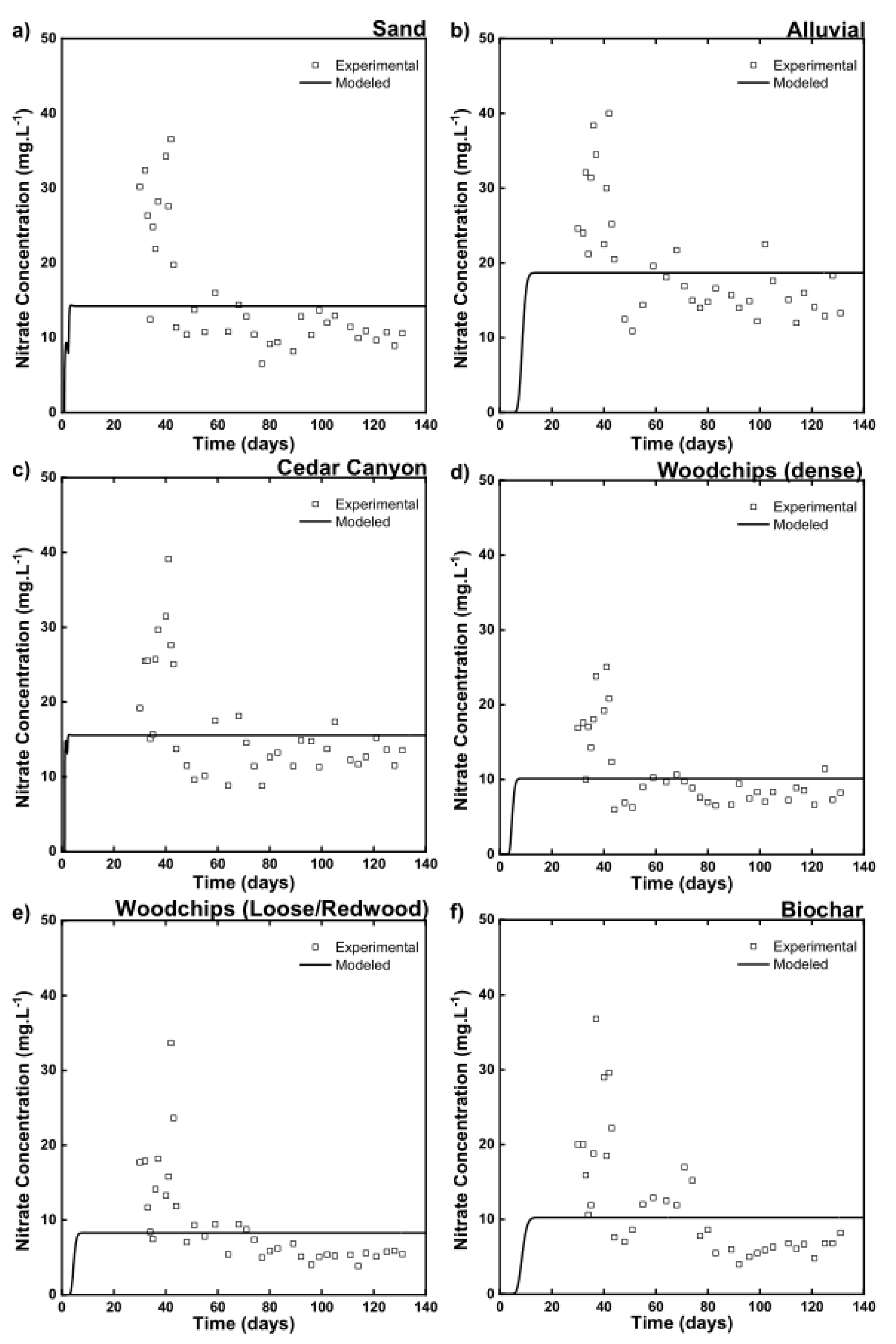
3.2. Nitrate Parameter Calibration Using Observed Nitrate Concentration

A constant flux of wastewater was applied to the soil columns. The wastewater was collected from the Rapid City Wastewater Treatment Plant. The wastewater had a known concentration of 28.0 mg/L of nitrate. The denitrification reaction from nitrate to nitrogen gas is considered a first-order anaerobic reaction with no sorption [20]. Leachate samples were collected and compared to the modeled output concentration. Measured nitrate concentration data were limited compared to the data used to determine soil hydraulic parameters. Thus, manual calibration was used. Calibration was performed based on the average nitrate effluent concentrations. This was compared to the effluent nitrate concentration at a steady state in the model. The first-order reaction rates were adjusted until the modeled effluent concentration matched the average experimental concentration.
The layered columns include carbon-based media with cedar canyon soil both on the top and bottom of the column. Each layer is of equal thickness of 16.6 cm. The calibrated solute parameters from the homogenous cedar canyon column were used for the cedar canyon layers. The carbon-based layers were then calibrated by changing the middle layer’s first-order reaction rate constant for the middle layer only. For the biochar column, the top and bottom cedar canyon layers were assumed to have the same reaction rate as the homogenous cedar canyon column.
The first-order denitrification rate was determined by changing the 1st order reaction rate constant until the modeled effluent concentration matched the average observed experimental concentration. Table 3 shows the average effluent nitrate concentration from the experimental models, as well as the calibrated denitrification reaction rate constant.
The experimental results show that nitrate removal is observed to dramatically increase with the use of carbon-based media. The first-order reaction rate constant did not change much from the soil media to the carbon-based media. This is because the model has a water content function (Walker’s equation, Equation (10)) that increases the reaction rate as the water content increases. Thus, with identical reaction rates, the carbon-based material has a higher removal attributable to higher content. In Section 3.1, it was observed that the woodchip and biochar layers had a major effect on increasing the water content in the woodchip and biochar layers. Equations (8)–(10) give the reasoning as to why the water content increased nitrate removal. It is seen in each equation that the water content affected removal (Equation (8)), dispersion of nitrate (Equation (9)), and the filled pore space in Walker’s Equation (10). One of the limitations of the model in distinguishing between the various factors that influence nitrate removal (e.g., water content versus carbon content). The results of the nitrate treatment calibration are shown in Figure 4a–f. This is followed by Figure 5a,b, which shows the vertical nitrate concentration distribution produced by HYDRUS 2D.
Higher nitrate removal efficiencies were observed in woodchips and biochar. Therefore, the removal efficiencies compared with previous studies are shown in Table 4. The comparison showed that initial nitrate concentrations play an important role in removal efficiency. The removal performances of the media decreased with increasing initial concentrations. This is because of the faster saturation of the available removal sites in the case of a higher initial concentration. The removal performance of the media also depends on the input wastewater components. However, the media we used performed relatively well in nitrate removal compared to other studies.
The HYDRUS 2D graphical output for nitrate concentration compared to the depth for each of the calibrated columns is shown in Figure 6a–f.
The difference from the homogenous soil columns was minimal, and there was only an observed difference in the nitrate treatment once an increased water content was observed. For both the dense and loose woodchip layers, a sharp increase in nitrate treatment was observed, while in the biochar layer, no changes were seen in the nitrate treatment performance until the mixed layer where the observed water content was much higher compared to the homogenous cedar canyon column.

3.3. Sensitivity Analysis

The parameter inputs and results for the sensitivity analysis are shown in Section S5 and Tables S6–S11 in the Supplementary File. The values displayed are the percent difference from the original effluent nitrate concentration. The average experimental effluent nitrate concentration for the sand, loose woodchips, and biochar columns was found to be 14.22, 9.49, and 16.6 mg/L in the corresponding order.
Through sensitivity analysis, it was found that three major parameters affected nitrate treatment performance. The major factors were the saturated water content, Van Genuchten parameter α, and the first-order reaction constant. The saturated water content and α were parameters that had a major impact on the overall water content of the column. Meanwhile, k, the first-order reaction constant, had a direct impact on the solute concentration. Figure S6a–c in the Supplementary File shows a summary of the effect on the effluent nitrate concentration by changing the respective parameters.
It was unexpected that the water content of the soil would have such a large impact on nitrate transport and reaction through the column. Looking at Equations (6)–(8), in Section 2.2.2, it is seen that the water content is a direct modifier to the first-order reaction rate and the dispersion/diffusion within the column. This is the reason that the biochar column was able to remove more nitrate than the cedar canyon column, even if the Biochar first-order reaction rate constant was 0.032 compared to Cedar Canyons reaction rate of 0.278. The biochar column was much more efficient in retaining water in the column, increasing the denitrification reaction rate. The effect of water content would also explain the 6% difference between the compacted and uncompacted woodchip columns. This is explained by the fact that denitrification is an anaerobic reaction and will occur faster with a lack of oxygen. This means that soils that are capable of retaining water longer while still allowing for adequate flow will be the most effective in nitrate removal.

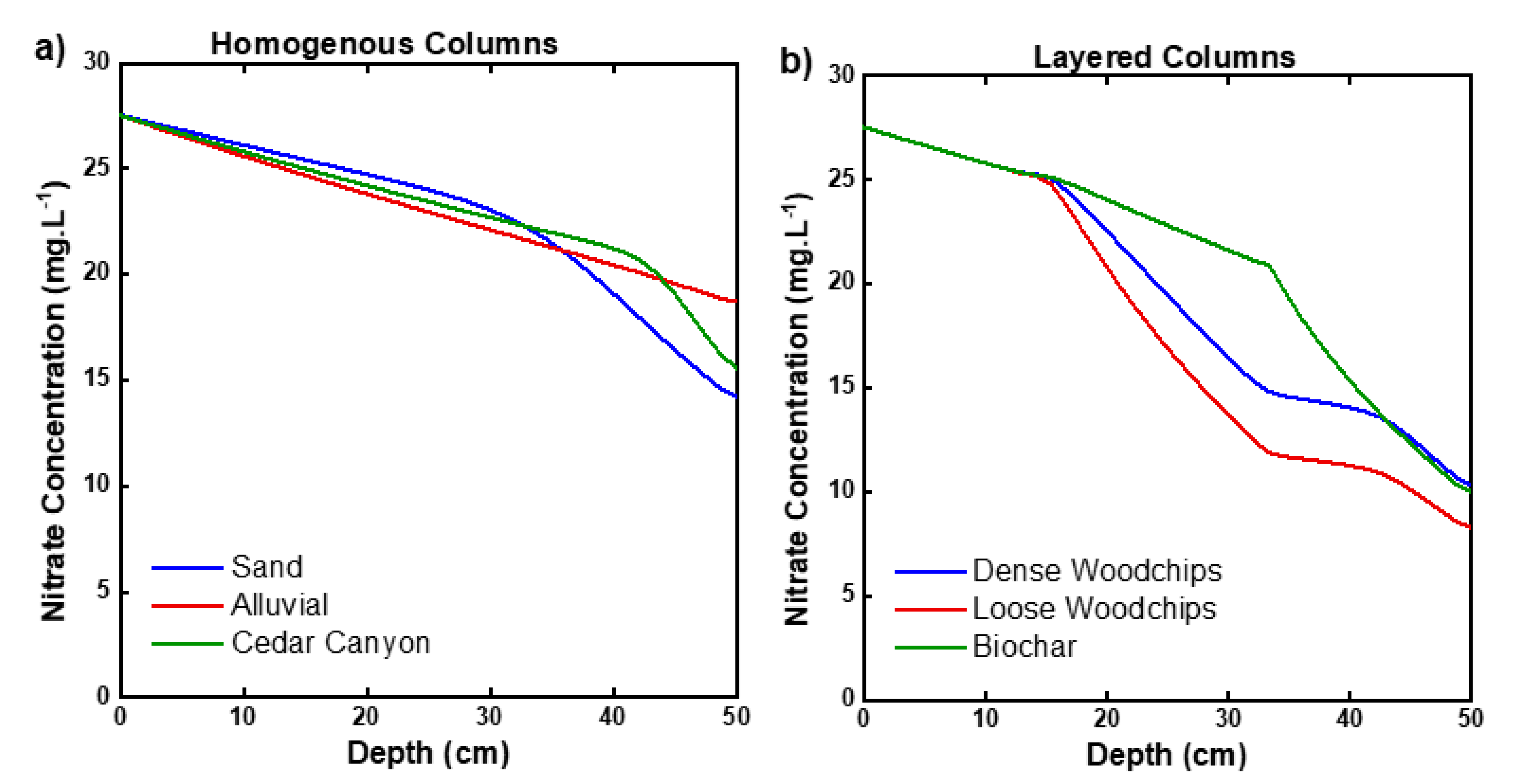
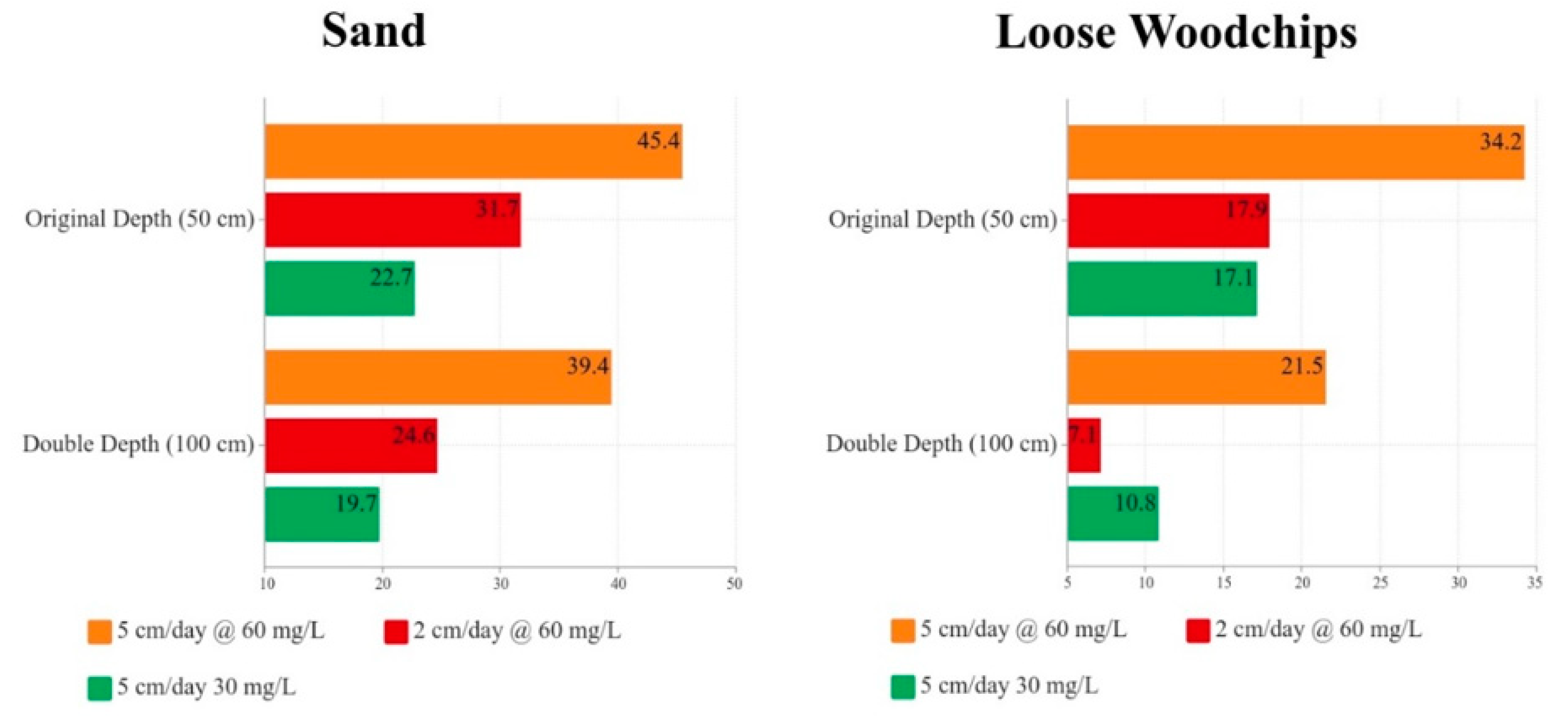
3.4. Scenario Analysis Modeling

Six different scenarios based on flux rate, influx concentration, and flow depth are shown in Table 5, which provides a summary of each of the analyzed scenarios.
Figure 7 shows the scenario analysis results of the sand column. It was observed that by increasing the hydraulic loading rate by 250%, the nitrate effluent only increased by 50%. The results of doubling the column depth had minimal impact, as the average nitrate effluent concentration was reduced by less than 20% for each of the loading rates and water quality scenarios.
Figure 7 shows the results of the loose woodchip column scenario analysis. As the depth of the soil column doubled, the effluent nitrate concentration was reduced by roughly 40% for both hydraulic loading rates of 5 cm/day. For the hydraulic loading rate of 2 cm/day there was a reduction of 60%. When the hydraulic loading rate was increased by 250% with the same water quality, the nitrate effluent increased by 200% for the original column depth. At the doubled depth, there was an increase in nitrate effluent of over 300%. The loose woodchips operate under a low hydraulic loading rate, the best with thick soil columns.
Some important factors should be considered when implementing the study findings in the field design. As seen in this study, the effect of a higher water content had a major effect on the denitrification reaction rate. For all OWTS, the leeching field should be designed to create highly saturated soil below. This will help increase the denitrification reaction rate, reducing the amount of nitrate leaching into groundwater. Lastly, the implementation of loosely compacted woodchips below the leeching field should be used in areas where karst formations are known to occur. The use of woodchips will increase the level of saturation, and the presence of carbon will increase the denitrification rate.

4. Conclusions

The increased usage of onsite wastewater systems in the Black Hills poses a threat to the water supply. With the increased number of OWTS in use, nitrate concentrations have been on the rise in the Black Hills. The nitrate treatment performance of soils will become increasingly important as septic tank density increases. The work in this study focused on analyzing the treatment performance of common soils from Black Hills and other carbon-based soil media. The soil media included two soils from the Black Hills (alluvium and silty sand), sand, compacted woodchips, loose woodchips, and biochar. Experimental soil columns were made with each of the soil media, with the carbon-based media included as a layered component. The numerical model was instrumental in understanding water movement and nitrate treatment performance through various media. The hydraulic calibration reached good agreement between the measured and model-predicted soil moisture content, with R2 values ranging from 0.57 to 0.99. The lower R2 values were due to the steady increase in the observed water content over time. A high R2 was achieved because the soil columns reached a constant steady state. All carbon-based soil media showed increased nitrate treatment performance from wastewater filtration. The most effective nitrate treatment media were found to be loosely compacted woodchips. This is thought to be the result of the increased water content that enhanced the anaerobic denitrification reaction. The total effect of replacing the middle third layer soil with carbon-based media increased the nitrate treatment performance from 34% to 65%. The sensitivity analysis showed that the major factors for improving nitrate removal efficiency included the saturated water content and the denitrification rate. This is to be expected, as the denitrification rate has a direct effect on removal efficiency. The saturated water content is due to denitrification being an anaerobic reaction requiring a lack of oxygen. This was achieved using Walker’s equation, which implemented the effect of increased saturations having a higher denitrification reaction rate.

Supplementary Materials

The following supporting information can be downloaded at: https://www.mdpi.com/article/10.3390/cleantechnol4030051/s1, File: Supplementary File-S1.

Author Contributions

Conceptualization, M.S.H. and M.G.; methodology, M.S.H. and M.G.; software, J.T., M.S.H. and M.G.; validation, J.T., M.S.H. and M.G.; formal analysis, J.T. and M.S.H.; investigation, J.T., M.S.H. and M.G.; resources, M.G.; data curation, J.T. and M.S.H.; writing—original draft preparation, J.T., M.S.H. and M.G.; writing—review and editing, J.T., M.S.H. and M.G.; visualization, M.S.H. and M.G.; supervision, M.S.H. and M.G.; project administration, M.G.; funding acquisition, M.G. All authors have read and agreed to the published version of the manuscript.

Funding

This research was funded by the USGS 104b Grant Program (3TQ861) and the Civil and Environmental Engineering Department, South Dakota School of Mines and Technology.

Institutional Review Board Statement

Not Applicable.

Informed Consent Statement

Not Applicable.

Data Availability Statement

Not Applicable.

Acknowledgments

The authors would like to acknowledge Forest Cooper for his support in setting up the column frame and acquiring materials.

Conflicts of Interest

The authors declare no conflict of interest.

References

  1. Bdour, A. Perspectives on sustainable wastewater treatment technologies and reuse options in the urban areas of the Mediterranean region. In Proceedings of the World Environmental and Water Resources Congress 2007: Restoring Our Natural Habitat, Tampa, FL, USA, 15–19 May 2007; pp. 1–15. [Google Scholar]
  2. Geza, M.; McCray, J.E. Modeling the effect of population growth on stream nutrient concentration in turkey creek watershed using the WARMF model. In Proceedings of the Eleventh Individual and Small Community Sewage Systems Conference, Warwick, RI, USA, 20–24 October 2007; p. 9. [Google Scholar]
  3. Hojjati-Najafabadi, A.; Mansoorianfar, M.; Liang, T.; Shahin, K.; Karimi-Maleh, H. A review on magnetic sensors for monitoring of hazardous pollutants in water resources. Sci. Total Environ. 2022, 824, 153844. [Google Scholar] [CrossRef] [PubMed]
  4. Siegrist, R.L. Advancing the science and engineering of onsite wastewater systems. In Proceedings of the On-Site Wastewater Treatment, Armidale, Australia, 25–27 September 2001; p. 1. [Google Scholar]
  5. Van Cuyk, S.; Siegrist, R.; Logan, A.; Masson, S.; Fischer, E.; Figueroa, L. Hydraulic and purification behaviors and their interactions during wastewater treatment in soil infiltration systems. Water Res. 2001, 35, 953–964. [Google Scholar] [CrossRef]
  6. Tchobanoglous, G.; Burton, F.L.; Stensel, H. Solution Manual for Use With Wastewater Engineering: Treatment and Reuse; McGraw-Hill: New York, NY, USA, 2003. [Google Scholar]
  7. Robbins, D.M.; Ligon, G.C. How to Design Wastewater Systems for Local Conditions in Developing Countries; IWA Publishing: London, UK, 2014. [Google Scholar]
  8. Akter, A. Groundwater Recharge. In Rainwater Harvesting—Building a Water Smart City; Springer: Berlin/Heidelberg, Germany, 2022; pp. 191–214. [Google Scholar]
  9. Beach, D.N.; McCray, J.E.; Lowe, K.S.; Siegrist, R.L. Temporal changes in hydraulic conductivity of sand porous media biofilters during wastewater infiltration due to biomat formation. J. Hydrol. 2005, 311, 230–243. [Google Scholar] [CrossRef]
  10. Geza, M.; Lowe, K.S.; Huntzinger, D.N.; McCray, J.E. New conceptual model for soil treatment units: Formation of multiple hydraulic zones during unsaturated wastewater infiltration. J. Environ. Qual. 2013, 42, 1196–1204. [Google Scholar] [CrossRef] [PubMed]
  11. Bradshaw, J.K.; Radcliffe, D.E.; Šimůnek, J.; Wunsch, A.; McCray, J.E. Nitrogen fate and transport in a conventional onsite wastewater treatment system installed in a clay soil: A nitrogen chain model. Vadose Zone J. 2013, 12, 1–20. [Google Scholar] [CrossRef] [Green Version]
  12. Radcliffe, D.; Amador, J.; Atoyan, J.; Boving, T.; Kalen, D.; Loomis, G. State of the Science: Review of Quantitative Tools to Determine Wastewater Soil Treatment Unit Performance; The Water Research Foundation: Denver, CO, USA, 2009. [Google Scholar]
  13. Hasan, M.S.; Vasquez, R.; Geza, M. Application of Biochar in Stormwater Treatment: Experimental and Modeling Investigation. Processes 2021, 9, 860. [Google Scholar] [CrossRef]
  14. Hasan, M.S.; Geza, M.; Vasquez, R.; Chilkoor, G.; Gadhamshetty, V. Enhanced Heavy Metal Removal from Synthetic Stormwater Using Nanoscale Zerovalent Iron–Modified Biochar. Water Air Soil Pollut. 2020, 231, 220. [Google Scholar] [CrossRef]
  15. Kabir, T.; Hasan, M.S.; Das, P. Applicability of Activated Carbon Filtration in Surface Water Treatment. Asian J. Innov. Res. Sci. Eng. Technol. 2018, 1. Available online: http://engineeringjournal.info/index.php/AJIRSET/article/view/28 (accessed on 9 May 2022).
  16. Akber, M.; Islam, M.; Dutta, M.; Billah, S.M. Nitrate contamination of water in dug wells and associated health risks of rural communities in southwest Bangladesh. Environ. Monit. Assess. 2020, 192, 163. [Google Scholar] [CrossRef]
  17. Ramalingam, G.; Nagapandiselvi, P.; Priya, A.; Rajendran, S. A review of graphene-based semiconductors for photocatalytic degradation of pollutants in wastewater. Chemosphere 2022, 300, 134391. [Google Scholar] [CrossRef]
  18. Geza, M.; Lowe, K.S.; McCray, J.E. STUMOD—A tool for predicting fate and transport of nitrogen in soil treatment units. Environ. Model. Assess. 2014, 19, 243–256. [Google Scholar] [CrossRef]
  19. Kabuba, J.; Lephallo, J.; Rutto, H. Comparison of various technologies used to eliminate nitrogen from wastewater: A review. J. Water Process Eng. 2022, 48, 102885. [Google Scholar] [CrossRef]
  20. McCray, J.E.; Christopherson, S.H. On-site wastewater systems and interactions with the environment. J. Hydrol. Eng. 2008, 13, 653–654. [Google Scholar] [CrossRef]
  21. Heinrich, C.J. Modeling Watershed-Scale Impacts of On-Site Wastewater Systems on Nitrogen Loadings in the Black Hills. Master’s Thesis, South Dakota School of Mines and Technology, Rapid City, SD, USA, 2021. [Google Scholar]
  22. Trapp, J. Experimental and Numerical Investigation and Improvement of Performance of Onsite Wastewater Systems. Master’s Thesis, South Dakota School of Mines and Technology, Rapid City, SD, USA, 2021. [Google Scholar]
  23. Waller, R.M. Ground Water and the Rural Homeowner; US Department of the Interior, US Geological Survey, U.S. Government Printing Office: Washington, DC, USA, 1994.
  24. Rahn, P.H. Sickness Caused by Septic Disposal Systems in the Black Hills. In Proceedings of the South Dakota Academy of Science, Rapid City, SD, USA, 24 July 2011. [Google Scholar]
  25. Long, A.J.; Sawyer, J.F.; Putnam, L.D. Environmental tracers as indicators of karst conduits in groundwater in South Dakota, USA. Hydrogeol. J. 2008, 16, 263–280. [Google Scholar] [CrossRef]
  26. Boulding, J.R.; Ginn, J.S. Practical Handbook of Soil, Vadose Zone, and Ground-Water Contamination: Assessment, Prevention, and Remediation; CRC Press: Boca Raton, FL, USA, 2016. [Google Scholar]
  27. Šimůnek, J.; van Genuchten, M.; Sejna, M. HYDRUS Technical Manual: The HYDRUS Software Package for Simulating the Two- and Three-Dimensional Movement of Water, Heat and Multiple Solutes in Variably-Saturated Porous Media; Technical Manual Version; PC Progress: Prague, Czech Republic, 2012; p. 2. [Google Scholar]
  28. Hasan, M.S.; Geza, M.; Petersen, J.B.; Gadhamshetty, V. Graphene oxide transport and retention in biochar media. Chemosphere 2021, 264, 128397. [Google Scholar] [CrossRef] [PubMed]
  29. Geza, M.; Deb, S.K.; Leinauer, B.; Stanek, S.; Sevostianova, E.; Serena, M. Modeling NO3–N leaching during establishment of turfgrasses irrigated with tailored reclaimed water. Vadose Zone J. 2021, 20, e20112. [Google Scholar] [CrossRef]
  30. Hasan, M.S.; Dong, J.; Gadhamshetty, V.; Geza, M. Modeling graphene oxide transport and retention in biochar. J. Contam. Hydrol. 2022, 248, 104014. [Google Scholar] [CrossRef]
  31. Rudaz, A.O.; Davidson, E.A.; Firestone, M.K. Sources of nitrous oxide production following wetting of dry soil. FEMS Microbiol. Lett. 1991, 85, 117–124. [Google Scholar] [CrossRef] [Green Version]
  32. Peters, R.W.; Walker, T.J.; Ku, Y.; Berdanier, B.; Chang, T.-K.; Freund, D. Physical and chemical methods. J. Water Pollut. Control Fed. 1983, 55, 599–612. [Google Scholar]
  33. Simunek, J.; Van Genuchten, M.T. Using the HYDRUS-1D and HYDRUS-2D codes for estimating unsaturated soil hydraulic and solute transport parameters. In Characterization and Measurement of the Hydraulic Properties of Unsaturated Porous Media; U.S. Salinity Laboratory, Agricultural Research Service, U.S. Department of Agriculture: Riverside, CA, USA, 1999; Volume 1, pp. 1523–1538. [Google Scholar]
  34. Ghane, E.; Feyereisen, G.W.; Rosen, C.J. Non-linear hydraulic properties of woodchips necessary to design denitrification beds. J. Hydrol. 2016, 542, 463–473. [Google Scholar] [CrossRef]
  35. Heath, R.C. Basic Ground-Water Hydrology; US Department of the Interior, US Geological Survey: Reston, VA, USA, 1998; Volume 2220.
  36. Kouanda, A.; Hua, G. Determination of nitrate removal kinetics model parameters in woodchip bioreactors. Water Res. 2021, 195, 116974. [Google Scholar] [CrossRef] [PubMed]
  37. Hoover, N.L.; Bhandari, A.; Soupir, M.L.; Moorman, T.B. Woodchip denitrification bioreactors: Impact of temperature and hydraulic retention time on nitrate removal. J. Environ. Qual. 2016, 45, 803–812. [Google Scholar] [CrossRef] [PubMed] [Green Version]
  38. Maxwell, B.M.; Birgand, F.; Schipper, L.A.; Christianson, L.E.; Tian, S.; Helmers, M.J.; Williams, D.J.; Chescheir, G.M.; Youssef, M.A. Drying–rewetting cycles affect nitrate removal rates in woodchip bioreactors. J. Environ. Qual. 2019, 48, 93–101. [Google Scholar] [CrossRef] [PubMed]
  39. Zhang, M.; Gao, B.; Yao, Y.; Xue, Y.; Inyang, M. Synthesis of porous MgO-biochar nanocomposites for removal of phosphate and nitrate from aqueous solutions. Chem. Eng. J. 2012, 210, 26–32. [Google Scholar] [CrossRef]
  40. Alagha, O.; Manzar, M.S.; Zubair, M.; Anil, I.; Mu’azu, N.D.; Qureshi, A. Comparative adsorptive removal of phosphate and nitrate from wastewater using biochar-MgAl LDH nanocomposites: Coexisting anions effect and mechanistic studies. Nanomaterials 2020, 10, 336. [Google Scholar] [CrossRef] [Green Version]
  41. Sui, M.; Li, Y.; Jiang, Y.; Wang, L.; Zhang, W.; Sathishkumar, K.; Zakaria, H. Sediment-based biochar facilitates highly efficient nitrate removal: Physicochemical properties, biological responses and potential mechanism. Chem. Eng. J. 2021, 405, 126645. [Google Scholar] [CrossRef]
  42. Li, R.; Wang, B.; Niu, A.; Cheng, N.; Chen, M.; Zhang, X.; Yu, Z.; Wang, S. Application of biochar immobilized microorganisms for pollutants removal from wastewater: A review. Sci. Total Environ. 2022, 837, 155563. [Google Scholar] [CrossRef]
Figure 1. Experimental Column Setup.
Cleantechnol 04 00051 g001
Figure 2. Calibrated Water Content for (a) Sand, (b) Alluvial, (c) Cedar Canyon, (d) Woodchips (dense), (e) Woodchips (Loose), and (f) Biochar.
Cleantechnol 04 00051 g002
Figure 3. Calibrated Water Content HYDRUS Graphical Outputs (a) Sand, (b) Cedar Canyon, (c) Alluvial, (d) Dense Woodchips, (e) Loose Woodchips, and (f) Biochar.
Cleantechnol 04 00051 g003
Figure 4. Calibrated Nitrate Concentration for (a) Sand, (b) Alluvial, (c) Cedar Canyon, (d) Woodchips (dense), (e) Woodchips (Loose), and (f) Biochar.
Cleantechnol 04 00051 g004
Figure 5. Vertical Nitrate Distribution in (a) homogeneous columns (Sand, Alluvial, and Cedar Canyon) and (b) layered columns (Woodchips (dense), Woodchips (Loose), and Biochar).
Cleantechnol 04 00051 g005
Figure 6. Calibrated Nitrate Concentrations HYDRUS Graphical Outputs: (a) Sand, (b) Cedar Canyon, (c) Alluvial, (d) Dense Woodchips, (e) Loose Woodchips, and (f) Biochar.
Cleantechnol 04 00051 g006
Figure 7. Scenario analysis results.
Cleantechnol 04 00051 g007
Table 1. Methods used to determine parameter values.
ParameterSandAlluvialCedar
Canyon
Dense
Woodchips
Loose
Woodchips
BiocharMixed
θ r
(cm3/cm3)
Study by Hasan et al. [13] Inverse modelingInverse ModelingStudy by Ghane et al. [34] Study by Ghane et al. [34]Study by Hasan et al. [30]Homogenous Cedar Canyon
θ s
(cm3/cm3)
Inverse ModelingStudy by R.C. Heath [35] Saturated Water Content TestSaturated Water Content TestHomogenous Cedar Canyon
α
(1/cm)
Soil Moisture Characteristic CurveInverse ModelingInverse ModelingInverse ModelingInverse Modeling
n Soil Moisture Characteristic CurveInverse ModelingInverse ModelingInverse ModelingInverse Modeling
K s
(cm/day)
Inverse ModelingStudy by R.C. Heath [35]Inverse ModelingInverse ModelingInverse Modeling
Table 2. Calibrated Hydraulic Parameters.
ParametersC1C2C3C4C5C6
SandAlluvialCedar CanyonDense WoodchipsLoose WoodchipsBiocharMix
θ r
(cm3/cm3)
0.0020.020.0010.210.210.0010.001
θ s
(cm3/cm3)
0.240.470.340.440.660.640.34
α
(cm−1)
0.0700.170.160.0460.1210.000010.11
n 4.451.345.974.334.473.071.35
K s
(cm/day)
72075068974611455425
R20.980.570.570.970.980.99
Table 3. Observed/Modeled Nitrate Solute Transport.
ParametersC1C2C3C4C5C6
SandAlluvialCedar
Canyon
Dense WoodchipsLoose WoodchipsBiocharMix
Observed/Modeled Concentration (mg/L)14.22/
14.25
18.71/
18.69
15.54/
15.55
10.14/
10.14
8.28/
8.26
10.25/
10.26
First Order Reaction Constant (1/day) 0.260.0450.280.170.240.0320.28
Table 4. Nitrate removal efficiencies of Woodchips and Biochar.
MediaInitial ConcentrationNitrate Removal EfficiencyReference
(mg/L)(%)
Woodchips1098.7[36]
3039 ± 9[37]
1079 ± 14[37]
5029 ± 12[37]
41.235 to 43[38]
2870.46Our Study
Biochar2015 to 20[39]
1020 to 40[40]
1057.1 ± 2.1[41]
10020.63[42]
2863.39Our Study
Table 5. Scenario analysis summary.
Scenario Flux Rate (cm/Day) Influx Concentration (mg/L) Flow Depth (cm)
Scenario 1 26050
Scenario 2 56050
Scenario 3 53050
Scenario 4 260100
Scenario 5 560100
Scenario 6 530100
Publisher’s Note: MDPI stays neutral with regard to jurisdictional claims in published maps and institutional affiliations.

