Abstract
In this work, Rhodiasolv® PolarClean was employed as a more sustainable solvent for the preparation of poly(vinylidene fluoride-hexafluoropropylene) (PVDF-HFP) flat sheet membranes via phase inversion technique by coupling vapour induced phase separation (VIPS) and non-solvent induced phase separation (NIPS) processes. Preliminary calculations based on Hansen solubility parameters well predicted the solubilization of the polymer in the selected solvent. The effect of exposure time on humidity and the influence of polyethylene glycol (PEG), polyvinyl pyrrolidone (PVP) and sulfonated polyether sulfone (S-PES) on membrane properties and performance, were evaluated. Three different coagulation bath compositions were also explored. The obtained membranes, prepared using a more sustainable approach, were compared with those produced with the traditional toxic solvent N-methyl-2-pyrrolidone (NMP) and characterised in terms of morphology, porosity, wettability, pore size, surface roughness and mechanical resistance. The potential influence of the new solvent on the crystallinity of PVDF-HFP-based membranes was also evaluated by infrared spectroscopy. The adjustment of the parameters investigated allowed tuning of the membrane pore size in the microfiltration (MF) and ultrafiltration (UF) range resulting in membranes with various morphologies. From the water permeability and rejection tests, performed with methylene blue dye, the prepared membranes showed their potentiality to be used in MF and UF applications.
1. Introduction
Polymeric membranes are used in a plethora of applications involving separation processes, spanning from gas separation and water treatment to haemodialysis. Their lower material and fabrication cost, ease of processability and flexibility, together with the possibility of producing a wide variety of pore sizes, make them the preferred choice in many fields of interest [1]. Among the various techniques employed for the preparation of polymeric membranes, phase inversion is the most widely used both in industry and academia [2]. It consists of dissolving a polymer in a suitable solvent and inducing the phase inversion applying external forces (non-solvent induced precipitation, vapour induced precipitation, thermally induced precipitation) or internal forces (evaporation induced phase separation) [3]. Solvents are the major constituents of a polymer dope solution accounting for up to 80–90% of the whole solution. N,N-dimethylformamide (DMF), N,N-dimethylacetamide (DMA) and N-methyl-2-pyrrolidone (NMP) are dipolar aprotic solvents, which are very effective in dissolving most of the polymers employed for the fabrication of polymeric membranes [4]. However, in view of the tighter environmental regulations adopted at national and international levels, the use of these solvents is becoming more and more restricted [5]. These solvents, in fact, can pose severe threats for human health and for the environment. NMP, for instance, is reprotoxic and irritating for the skin and eyes; DMF is hepatotoxic and reprotoxic [6], while DMA has also been categorized as a substance of very high concern due to its reproductive toxicity [4]. The use of these solvents, most of the times, is not merely confined to the preparation of the dope solution since their initial amount is completely found in wastewater after the coagulation and rinsing of the membrane [7]. It is, therefore, imperative to find new benign and more sustainable candidates that are able to replace the traditional harmful and toxic solvents. During the last few years, significant advances have been made in this direction where a new class of green and more sustainable solvents have been explored in the preparation of polymeric membranes. Ethyl lactate [8], triethyl phosphate [9], dimethyl sulfoxide [10] and ionic liquids [11] have been demonstrated to be valid candidates for the replacement of classic solvents in membranes prepared by phase inversion. Table 1 compares the physical properties, the environmental impact and the hazard level of a series of traditional toxic solvents, greener solvents and bio-based solvents.

Table 1.
Physical properties, environmental impact and hazard level for conventional toxic, greener and bio-based aprotic solvents employed in membrane preparation.
Dimethyl isosorbide (DMI), for instance, was recently proposed as a new green bio-based solvent for the preparation of polyether sulfone (PES) and poly(vinylidene fluoride) (PVDF) membranes [12]. DMI can be obtained from the anhydro sugar isosorbide and, thanks to its favourable toxicological profile, it is employed as a pharmaceutical additive and in the formulation of personal-care products [13]. By acting on the exposure time to humidity, the authors demonstrated the possibility of tuning membrane pore size, with both polymers in the microfiltration (MF) and ultrafiltration (UF) range and without requiring the use of any other pore forming additive.
Dihydrolevoglucosenone (CyreneTM), is another non-toxic biosolvent derived from cellulose, which was employed for the fabrication of porous PES and PVDF membranes for potential applications in water treatment processes [14]. In particular, the different evaporation times employed were found to be crucial for the determination of the final membrane morphology and features.
Methyl-5-(dimethylamino)-2-methyl-5-oxopentanoate (Rhodiasolv® PolarClean, from now on identified as PolarClean) is a recent eco-friendly green solvent with an excellent eco-toxicological profile [15]. PolarClean is, in fact, biodegradable, not irritating for the skin, not mutagenic and it does not present particular concerns for human health or for the environment [15]. Moreover, it is fully miscible with water, allowing the possibility of its use for the preparation of membranes by the non-solvent induced phase separation (NIPS) technique, and it presents a high boiling point (280 °C), which makes it ideal to be used for the preparation of membranes by the thermally induced phase separation (TIPS) technique.
PolarClean has already been proposed as a solvent for the preparation of PES based membranes in flat sheet and hollow fiber configuration [15,16] by NIPS, and for the preparation of PVDF flat sheet membranes [17] and hollow fibers [18] by TIPS at high temperatures (140–160 °C). However, from an industrial point of view, NIPS, due to its versatility, is the best technique to be employed for the preparation of polymeric membranes.
In this work, for the first time, PolarClean was employed as a green solvent for the preparation of polyvinylidene fluoride-co-hexafluoropropylene (PVDF-HFP) flat sheet membranes by coupling vapour induced phase separation (VIPS) and NIPS techniques. The approach herein proposed represents an advancement in the redesign of PVDF-based membrane preparation using green solvents in the light of the more and more stringent international regulations pertaining to the use of hazardous and toxic chemicals. PVDF-HFP is the copolymer of PVDF and, with respect to the homopolymer, presents with higher solubility, lower crystallinity, larger free volume, lower glass transition temperature and higher hydrophobicity as a consequence of the incorporation of fluoropropylene (HFP) in the vinylidene fluoride (VDF) blocks [19]. PVDF-HFP-based membranes have been employed until now in a plethora of applications including membrane distillation [20], pervaporation [21], Li-ion batteries [22], gas absorption [23] and water treatment [24].
In this work, the use of PVDF-HFP allowed the preparation of membranes at a lower temperature (80 °C) with respect to PVDF membranes prepared so far with PolarClean. Hansen solubility parameters (HSPs) provided a good preliminary indication of polymer solubility in the chosen solvent.
Different exposure times to humidity, the presence of different additives in the dope solution and the coagulation bath composition have been investigated in order to produce membranes with different properties and performance. The membranes produced with the more sustainable approach were compared with the membranes prepared, under the same conditions, with the traditional toxic solvent NMP.
The obtained membranes were, then, fully characterized in terms of morphology, polymer polymorphism, surface roughness, wettability, pore size, porosity and mechanical resistance. Their possible application in water treatment processes was also studied in terms of hydraulic permeability and rejection to methylene blue (MB) dye.
2. Materials and Methods
2.1. Materials
PVDF-HFP-Solef® 21,510 polymer (MW: 290–310 KDa; melting point: 135 °C; density: 1.77 g·cm−3) and PolarClean solvent (boiling point: 278−282 °C; water solubility >490 gdm−3 at 24 °C; density: 1.043 g·cm−3) were kindly supplied by Solvay Specialty Polymers (Bollate (MI), Italy) and by Solvay Novecare (Lyon, France), respectively. Sulfonated polyether sulfone (S-PES) (Mw ~130 Kg/mol, water contents ≤3%, sulfonation degree 30%), was supplied by Konishi Chemical Industry Co., Ltd., Wakayama, Japan. Polyethylene glycol (PEG) 200 (Mw = 0.2 kg/mol; melting point −65 °C; viscosity 0.04 St) was purchased from Sigma Aldrich (Milan, Italy) and polyvinyl pyrrolidone (PVP-K17) (Mw ~9 kg/mol, solid content 95–100%, residual NVP content ≤100 ppm, melting point: 130 °C) was purchased from BASF (Ludwigshafen, Germany). Ethanol and isopropanol were bought from Sigma Aldrich (Milan, Italy) and were used for coagulation baths. Distillate water was also used at 15 °C for coagulation bath and at 60 °C for membrane washing treatments.
2.2. Hansen Solubility Parameters (HSPs), Cloud Point Measurements and Ternary Phase Diagram
The HSPs of polymer and solvents were obtained from the literature. The mutual affinity between PVDF-HFP, solvents (PolarClean, NMP, DMF and DMA) and non-solvents (water, ethanol and isopropanol) was determined by calculating the solubility parameter ΔA−B (1)
where δd is the dispersion cohesion parameter, δh is the hydrogen bonding cohesion parameter and δp is the polar cohesion parameter, A is the polymer (PVDF-HFP) and B is the solvent or the non-solvent.
Cloud points were determined by the titration method (25 °C) by adding water dropwise to the polymer solution maintained under continuous stirring. The addition of water was carried out until the polymer solution became turbid (cloudy). At this point, the amount of water necessary to reach the cloud point was registered. The ternary phase diagram was realized by plotting the results stemming from different polymer/solvent concentrations, which allowed the determination of the binodal curve. For the cloud points measurements, the polymer concentrations investigated were 8, 10, 12, 14 and 16 wt% dissolved in NMP and PolarClean.
2.3. Membrane Preparation
The solutions were prepared by adding the PVDF-HFP polymer powder (10 wt%), previously dried in oven at 40 °C overnight, into PolarClean solvent and mixed at 80 °C for 2 h until complete dissolution. For the membranes prepared with additives, PVP (3 wt%) and PEG (15 wt%) were added, after the polymer, to the dope solution that was mixed at 80 °C until it became homogenous (about 2 h). When S-PES was used, it was added to the polymer solution with a concentration of 5 wt% (with respect to the overall polymer) in combination with PVP and PEG, keeping constant the overall polymer concentration (10 wt%).
Each solution, with and without additives, was then cast by using a manual casting knife with a gap of 250 µm (Elcometer 3700/1 Doctor Blade, Germany) on a glass plate in a climatic chamber under controlled temperature and humidity (25 °C and 55%, respectively). The membranes were formed by NIPS technique (by immediately immersing the cast film into the coagulation bath) or by VIPS/NIPS technique. In the latter case, the exposure time to humidity (VIPS) of the cast film was set at 2.5 and 5 min before immersion in the coagulation bath (NIPS). The coagulation bath was composed of water or a mixture (50:50) of water/ethanol and water/isopropanol.
Once formed, the membranes were washed three consecutive times in hot water (60 °C) and then dried in an oven overnight at 50 °C. In Table 2, the details of each dope solution composition and preparation conditions employed are reported along with the membrane codes.

Table 2.
Dope solutions’ compositions and investigated conditions to produce PVDF-HFP membranes.
2.4. Characterization Tests
Surface and cross-section images of prepared membranes were acquired by scanning electron microscopy (SEM, Zeiss EVO, MA100, Assing, Monterotondo, Italy). The samples were sputter coated with a thin layer of gold (sputter machine Quorum Q 150R S) before SEM observation.
The mean pore size was determined using a PMI Capillary Flow Porometer (CFP1500 AEXL, Porous Materials Inc., Ithaca, NY, USA) by previously soaking the membrane samples in Fluorinert FC-40 used as a wetting liquid.
For the determination of the porosity, membrane samples were weighed before and after immersion in isopropanol for 24 h.
The membrane porosity was calculated by means of the following Equation (2)
where Ww is the weight of the wet membrane, Wd is the weight of the dry membrane, ρk is the density of isopropanol (0.78 g cm−3) and ρp is the polymer density (1.77 g cm−3).
The measurements were carried out on three different samples of the membrane.
Membrane thickness was measured analysing cross-section images with ImageJ software.
The water contact angle of membrane top surfaces was measured by using a CAM 200 instrument (CAM 200, KSV instruments, Helsinki, Finland).
The membranes’ mechanical properties were measured using a ZWICK/ROELL Z 2.5 test unit (Ulm, Germany). Each sample (1 × 5 cm) was stretched unidirectionally at the constant speed of 5 mm/min.
The surface roughness of selected membranes was analysed by atomic force microscopy (AFM) using a Bruker Multimode 8 with NanoScope V controller. Data were acquired in tapping mode, using silicon cantilevers (model TAP150, Bruker, Billerica, MA, USA). The images were collected in a scan size of 5 μm × 5 μm.
Fourier transform infrared (FT-IR) spectroscopy measurements were carried out using a PerkinElmer Spectrum One spectrometer for investigating the different PVDF-HFP crystalline phases.
2.5. Water Permeability and MB Rejection Tests
Water permeability of selected membranes was measured using a cross-flow unit (DeltaE S.r.l., Rende, Italy). The water was fed to the membrane cell (active area of 8 cm2) by means of a gear pump (Tuthill Pump Co., Pulaski Rd, Alsip, IL, USA) and the transmembrane pressure was controlled using two manometers placed before and after the membrane. Water permeability was calculated at the steady state condition (stabilization time of 10 min) at 0.6 bar, using the following Equation (3)
where Q is the permeate volume (L), A is the membrane area (m2), t is the time (h) and p is the transmembrane pressure (bar).
MB filtration experiments were carried out using the same filtration set-up described above for water permeability. An aqueous MB solution (10 mg/L) was fed to the membrane cell and filtered through the membrane at 0.6 bar for 2 h. Permeate samples were collected at the end of the filtration and analysed by spectrophotometer (Shimadzu UV-160A, Kyoto, Japan) at a wavelength of 664 nm. The MB rejection (R) was calculated using Equation (4)
where Cp is the concentration of MB in the feed and Cp is the concentration of MB in the permeate.
3. Results and Discussion
3.1. Effect of the Solvent
The solvent plays a crucial role in the formation of a polymeric membrane. Its function is not only limited to the solubilization of the polymer but it greatly influences, during the formation of the membrane, its morphology and properties. Therefore, replacing a traditional solvent (such as NMP) with a new one (such as PolarClean) can be quite challenging.
HSPs were preliminary employed in order to predict the solubility of PVDF-HFP in the new solvent. As can be seen from Table 3, PolarClean presents HSPs similar to those of traditional solvents (NMP, DMF and DMA) and close to PVDF-HFP, thus predicting a good solubility of the polymer in the new green solvent.

Table 3.
HSPs, polymer-solvent and polymer/non-solvent solubility parameter (ΔA−B).
A ternary phase diagram allows the study of the interactions between the polymer, solvent and non-solvent giving crucial information on the thermodynamic parameters entering into play during the formation of the membrane and at the basis of the different morphologies that can be obtained.
The ternary phase diagram of the PVDF-HFP/solvent/non-solvent system using PolarClean and NMP as solvents is reported in Figure 1. The ternary phase diagram is represented by a single-phase region, characterized by a homogenous stable solution, and a two-phase region, characterized by a solution instability where the liquid–liquid demixing occurs, allowing the formation of a polymer rich and a polymer poor region. The binodal curve, experimentally determined by the cloud point measurements, delimits the two regions inside the triangle area.
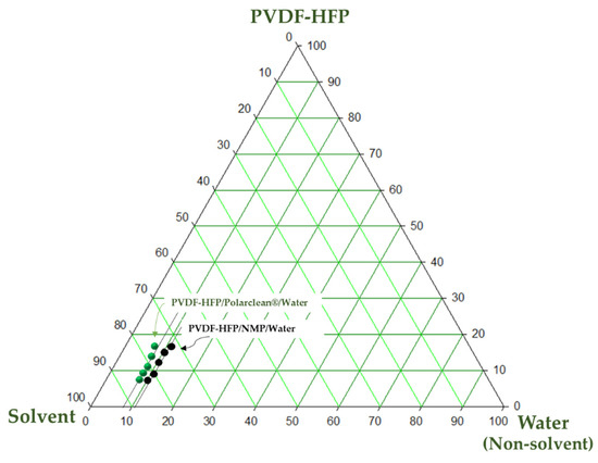
Figure 1.
Ternary phase diagrams for PVDF-HFP/PolarClean/water and PVDF-HFP/NMP/water systems.
As shown in Figure 1, the binodal curve of the PVDF-HFP/PolarClean/water system is closer to the axis of the polymer and solvent, showing lower thermodynamic stability. This results in a lower amount of water (non-solvent) necessary to promote the demixing of the system. On the contrary, when NMP is employed as a solvent, the single-phase region is wider due to a bigger water tolerance with a slower demixing rate.
The results agree with HSPs reported in Table 3, which well predicted the higher instability of the PVDF-HFP/PolarClean system with respect to the PVDF-HFP/NMP system, as can be deduced by the higher solubility parameter ΔA−B of the mixture polymer—PolarClean (2.48 MPa1/2) with respect to the mixture polymer—NMP (1.29 MPa1/2).
The demixing rate is fundamental in determining membrane morphology: generally, a fast demixing induces the formation of membranes characterized by a macrovoid or finger-like structure, while a delayed demixing leads to the formation of sponge-like structures [14,34].
Figure 2 shows the membranes prepared by dissolving PVDF-HFP in NMP at three different exposure times to humidity (0, 2.5 and 5 min). All of the membranes exhibit an asymmetric structure with a porous surface and a porous sub-layer. Particularly for the membranes prepared by VIPS-NIPS, macrovoids developed across the cross-section.
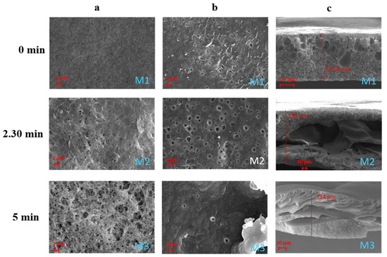
Figure 2.
SEM images illustrating the effect of the exposure time to humidity on PVDF-HFP/NMP membranes M1–M3: (a) top surfaces; (b) bottom surfaces; (c) cross-sections.
Macrovoids are generally related to a fast phase inversion process during membrane formation [35]. In this case, the low polymer concentration employed (only 10 wt%) led to an accelerated demixing rate, which promoted the generation of a macrovoid structure.
The effect of humidity on the membrane surface morphology is quite evident. The membrane prepared via NIPS (membrane M1), in fact, shows a surface characterised by small pores uniformly distributed. However, the surface pore size results were much more enhanced when the membranes were exposed, for a certain time, to humidity before coagulation (membranes M2–M3). The higher absorption of water molecules from the humid environment promoted the formation of membranes with a larger pore size [36]. All of the membranes showed a hydrophobic character with contact angle values between 96 and 121° (see Table 4) in agreement with the hydrophobic nature of the polymer. The differences in surface contact angle values for the M1–M3 membranes can be related to their different surface roughness. According to the model developed by Cassie–Baxter [37], in fact, porous surfaces show higher apparent contact angles as a consequence of the lower surface area in contact with the water droplet due to the air pockets formed within the pores of the surface.

Table 4.
Mean pore size, thickness, porosity and contact angle of the M1–M6 membranes.
The membranes prepared in PolarClean also showed an asymmetric structure characterised by porous top and bottom surfaces and by the presence of macrovoids along the cross-section (Figure 3). The effect of humidity on the membranes’ surfaces was, in this case, less pronounced. This can be related to the different viscosity of the dope solutions prepared with the two solvents. The viscosity of PolarClean, in fact, is 9 mPa*s which is much higher than that of NMP (1.67 mPa*s) [16,38]. For this reason, the dope solution prepared with PolarClean, at the same polymer concentration and temperature, presented a higher viscosity than that prepared with NMP. This could have led to a slower absorption of water molecules during the VIPS process. Generally, the NIPS technique generates membranes characterised by a dense skin layer and a porous support [17]. The dense top layer is created as a consequence of the polymer solidification induced by a fast solvent outflow, while the porous sub-layer is the result of the liquid–liquid demixing of the solution, which separates into a polymer rich phase and a polymer lean phase [39]. In this case, the low polymer concentration employed (10 wt%) hindered the formation of a completely dense top layer in favour of a more porous surface structure. For the same reason, for all of the membranes evaluated, the sub-layer was characterised by the presence of macrovoids due to the high solvent–non-solvent mutual diffusion rate [40].
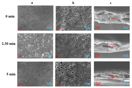
Figure 3.
SEM images illustrating the effect of the exposure time to humidity on PVDF-HFP/PolarClean membranes M4–M6: (a) top surfaces; (b) bottom surfaces; (c) cross-sections.
As shown in Table 4, all of the membranes prepared with NMP presented a pore size in the UF range. In particular, the M3 membrane showed the lowest pore size (0.03 µm), while the M2 membrane showed the highest value of pore size (0.05 µm).
The reason can be ascribed to the fact that, even if the surface of the M3 membrane appears, from SEM analyses, much more porous, the bottom layer is characterised by a more compact and less porous morphology. The membrane thickness was slightly affected by the exposure time to humidity. Membranes prepared by VIPS/NIPS technique presented higher thickness than those prepared by just NIPS.
The replacement of PolarClean as a solvent did not change to a great extent the membrane pore size. Additionally in this case, in fact, the membranes displayed a dimension of the pores in the UF range with values very close to the membranes prepared with NMP. With both solvents, by increasing the exposure time to humidity, the mean pore size first increased and then slightly decreased. This behaviour has also been observed by Marino et al. [15] in the preparation of PES membranes, and it was related to a change in membrane morphology when the exposure time exceeded 2.5 min. The contact angle of the M4–M7 membranes followed the same trend observed for the membranes prepared with NMP. It increased as the exposure time to humidity increased to 2.5 min, and then decreased when it reached 5 min as a consequence of the different surface roughness of the membranes (as shown in Figure 4).
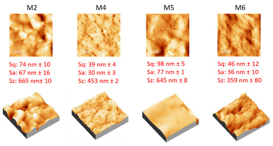
Figure 4.
AFM images, with corresponding 3D views, and roughness parameters of M2, M4, M5 and M6 membranes.
The porosity of the membranes (displayed in Table 4) was influenced by the type of solvent employed showing values close to 69% (for the membranes prepared with NMP) and 79% (for the membranes prepared with PolarClean). In the case of PolarClean, the porosity was enhanced when the VIPS technique was combined with NIPS reaching the maximum value of 79% (M5 and M6 membranes). The higher porosity observed for the membranes prepared in PolarClean can be related to the bigger cavities existing along the membrane structure as a consequence of a fast solvent/non-solvent demixing rate. While during the VIPS phase the higher viscosity of dope solutions prepared with PolarClean could have prevented the adsorption of water molecules from the air, during the NIPS process the exchange with water could have been promoted by the lower affinity of the polymer PVDF-HFP with PolarClean with respect to NMP. As can be seen from Table 3, in fact, the solubility parameter ΔA−B for the mixture polymer—PolarClean is higher (2.48 MPa1/2) with respect to the mixture polymer—NMP (1.29 MPa1/2). In general, the lower the ΔA−B value is, the higher the solubility of the polymer–solvent pair is. This means that the system polymer—PolarClean was much more prone to an instant demixing than the system polymer—NMP (as confirmed by cloud point measurements in the ternary phase diagram, Figure 1).
The topography of the membranes prepared with PolarClean (M4, M5 and M6) was studied by AFM analyses and expressed in terms of root mean square (Sq), average roughness (Sa) and peak to peak value (Sz), as reported in Figure 4. The results were also compared with a membrane prepared with NMP (M2). The M5 membrane showed the highest values of surface roughness, probably as a consequence of the presence of small polymer aggregates, which are visible on the SEM picture of its surface (Figure 3). M4, prepared by NIPS, showed the lowest values of roughness due to its lower porous surface with respect to the other membranes (in agreement with SEM pictures).
The mechanical properties (Young’s Modulus and elongation at break) of investigated membranes are reported in Figure 5. M1 presented the highest values of Young’s Modulus (36 MPa) and elongation at break (300%) as a consequence of its different morphology with respect to the other membranes. As shown in the SEM pictures, in fact, M1 showed a dominant sponge-like structure with a few macrovoids, which were prevailing in the other membranes. The presence of macrovoids and pores is generally responsible for the reduction in the membranes’ mechanical properties, acting as weak points in the membrane structure [41]. For both membranes, the increase in the exposure time to humidity led to a slight decrease in Young’s Modulus as a consequence of the pore size and porosity improvement. In general, in respect to the homopolymer, the introduction of HFP groups in PVDF results in an improvement of the mechanical properties as a consequence of a decrease in the membrane porosity and a reduction in the membrane crystallinity [42].
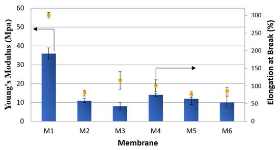
Figure 5.
Mechanical properties of M1–M6 membranes.
PVDF crystals have five different polymorphs (α, β, γ, δ and ɛ forms). Each polymorph can have an influence on membrane morphology and properties including mechanical properties, piezoelectricity and fouling behaviour [43]. The type of solvent employed to solubilize the polymer can affect the type of polymorph. In Figure 6, FT-IR measurements of M2 and M5 membranes, respectively prepared with NMP and PolarClean, are shown. In both cases, it was found that in these membranes, just the α and β crystalline forms coexist. In particular, the α-phase (the most kinetically stable form) appeared at 1402, 1383, 975, 976 and 761 cm−1; while the bands corresponding to the β-phase (the most thermodynamically stable form) appeared at 1064 and 840 cm−1 (just for M5 membrane) [44]. The predominance of the α-phase indicated that the crystallization process of the prepared membranes was mainly affected by kinetic factors.
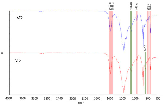
Figure 6.
FT-IR spectra of PVDF membranes prepared in NMP (M2) and PolarClean® (M5) as solvents.
3.2. Effect of the Additives and S-PES Polymer
A plethora of additives are commonly employed in order to impart peculiar properties to the final membrane. PVP and PEG are two of the most diffused additives, which are used for improving membrane pore size, porosity and hydrophilicity [45,46]. The influence of PVP and PEG on membrane morphology is shown in Figure 7. Both surfaces appeared to be characterised by a larger pore size, which was improved with the increase in the exposure time to humidity. The M7 membrane was characterised by a finger-like structure on the entire cross-section. A finger-like structure on a macrovoid’s sub-layer was observed for the M8 membrane, while M9 resulted in a sponge-like architecture. Finger-like and macrovoid structures are typical of systems where a rapid solvent/non-solvent exchange rate occurs [12]. This demonstrates that the exposure time plays a fundamental role during membrane formation in presence of hydrophilic agents and can be at the basis of the different structures observed for the M7–M9 membranes. As already observed by Susanto et al. [47], in fact, the exposure of the cast film to a humid environment delays the polymer precipitation resulting in membranes with a more closed structure with an evolution from finger-like to sponge-like structures (from M7 to M9).
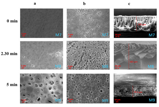
Figure 7.
SEM images illustrating the effect of the exposure time to humidity on PVDF-HFP/PolarClean membranes M7–M9 prepared with additives: (a) top surfaces; (b) bottom surface; (c) cross-sections.
By analysing the data reported in Table 5, it is also clear the effect the exposure time to humidity has on the membrane pore size. The M7 membrane prepared by the NIPS technique, showed the lowest value of pore size (0.05 μm). However, with respect to the membranes prepared by NIPS without additives (M1 and M4), the porogen effect of PVP and PEG is clear. The increase in the exposure time to humidity fostered the formation of larger pores reaching the highest value with the M9 membrane (0.96 μm). The porosity was almost constant and in the range between 76 and 80%. The increase in membrane pore size was not accompanied, in fact, with an increase in membrane porosity. The porosity values can be the result of a trade-off between membrane pore size and morphology. From one side, the largest pores of the membranes prepared by VIPS/NIPS (M8 and M9) positively affected the overall porosity, while, from the other side, the shift in membrane structure from a finger-like morphology (M7) to a sponge-like architecture (M9) negatively influenced the porosity.

Table 5.
Mean pore size, thickness, porosity and contact angle of the M7–M12 membranes.
Despite the clear effect of PVP and PEG on pore size, the hydrophilicity of the membranes was not greatly affected by their addition. This could be related to the fact that PVP and PEG are water soluble additives that are washed away from the membrane matrix during its formation via NIPS or during the subsequent washings of the membranes with hot water.
The mechanical properties (Figure 8) of M7–M9 membranes were very similar, in terms of Young’s Modulus, in comparison to the membranes prepared without additives (M4–M6). This can be related to the similar porosity values of both sets of membranes.
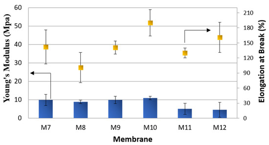
Figure 8.
Mechanical properties of M7–M12 membranes.
The elasticity of the membranes (elongation at break), on the contrary, was greatly improved by the addition of both fillers.
The use of S-PES polymer has been already investigated in blends for improving the performance of membranes in terms of pore size, porosity and water permeability [48]. In particular, the blend of S-PES with PVDF has been recognized as an efficient method for improving the hydrophilicity of neat PVDF membranes [49]. In this work, 5 wt% of S-PES (with respect to the polymer) was added in the PVDF dope solution keeping constant the overall polymer concentration (10 wt%).
The addition of S-PES led to a general improvement in the membranes’ pore size and porosity (membranes M10–M12 in Table 5). In this case, the pore size of all membranes fell in the MF range. The replacement of part of PVDF-HFP (molecular weight of 290–310 KDa) with S-PES (molecular weight of 130 KDa) led to a decrease in dope solution viscosity, favouring the passage of water molecules through the polymer chains and enhancing the formation of membranes with very open structures (as visible from Figure 9) [9]. The effect of the exposure time to humidity was, also in this case, preponderant in promoting the formation of larger pores on the membrane surfaces.
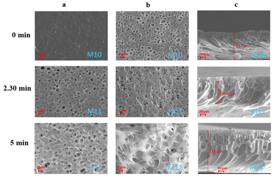
Figure 9.
SEM images illustrating the effect of the exposure time to humidity on PVDF-HFP/S-PES/PolarClean membranes M10–M12 prepared with additives: (a) top surfaces; (b) bottom surfaces; (c) cross-sections.
The hydrophilizing effect of S-PES on PVDF-HFP membranes was not noticeable, as evidenced by contact angle values, probably as a consequence of its low concentration in the dope solution (0.5 wt% of the total dope solution) and of the higher roughness of membranes prepared with this polymer (Figure 10). The addition of S-PES, in particular for the membranes prepared by the VIPS/NIPS technique (M11–M12), led to a decrease in the mechanical strength of the membranes (Figure 8) due to the very porous structure of these membranes.
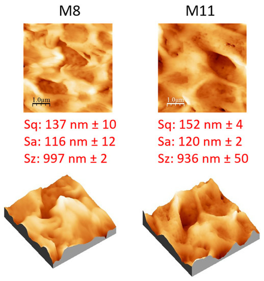
Figure 10.
AFM images, with corresponding 3D views, and roughness parameters of M8 and M11 membranes.
AFM analyses were carried out on M8 and M11 membranes prepared at the same exposure time to a humidity of 2.5 min (Figure 10). The effect of additives caused a general increase in membrane roughness, with respect to the pristine membranes prepared only with PVDF-HFP, as a consequence of the formation of a more porous surface structure. The M11 membrane (prepared with PVP, PEG and S-PES) presented a slightly higher roughness value than M8 (prepared with only PVP and PEG) due to its higher porosity and pore size.
3.3. Effect of Coagulation Bath
The effect of the coagulation bath composition (50 wt% ethanol, 50 wt% isopropanol) was evaluated for the membranes containing S-PES, PVP and PEG as additives and prepared by the VIPS/NIPS techniques, keeping constant at 2.5 min the exposure time to humidity (M13–M14). The results were compared with the same membrane type coagulated in water (M11). For the membranes prepared by NIPS technique, the coagulation bath plays a pivotal role in membrane formation. The miscibility of the solvent with the non-solvent, in fact, influences the exchange rate during the membrane formation, greatly affecting its structure and properties.
The use of ethanol in the coagulation bath (membrane M13), for instance, slowed down the precipitation rate of the polymer, leading to the formation of membranes with a closer structure (Figure 11) [50]. The same effect can be observed for the membrane prepared with isopropanol in the coagulation bath (membrane M14). This is because water is the strongest non-solvent for the polymer, followed by ethanol and isopropanol. The ΔA−B values for the different polymer/non-solvent pairs reported in Table 3, in fact, indicate a lower affinity of the polymer for water (ΔA−B: 34.31 MPa1/2), compared to ethanol (ΔA−B: 11.87 MPa1/2) and isopropanol (ΔA−B: 10.49 MPa1/2).
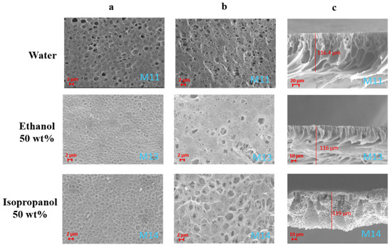
Figure 11.
SEM images illustrating the effect of the coagulation bath composition on PVDF-HFP/S-PES/PolarClean membranes M11, M13 and M14: (a) top surfaces; (b) bottom surfaces; (c) cross-sections.
The cross-section of the membranes turned from a finger-like/macrovoid structure (M11 and M13) to a more sponge-like architecture scattered with some macrovoids (M14), as shown in Figure 11. Pore size data, reported in Table 6, confirm the decrease in the pores’ dimension (but always in the MF range) as the alcohols were added in the coagulation bath with respect to the membranes coagulation in water. In particular, the pore size first decreased when ethanol was used in the coagulation bath and then increased again with the use of isopropanol. This trend agrees with the SEM surface images of the membranes shown in Figure 11. M11, in fact, presented a surface characterised by open-end pores, while the surfaces of M12 and M13 were mainly characterised by dead-end pores. Generally the use of alcohols in the coagulation bath promotes the formation of larger pores, as already observed for PVDF-HFP membranes [51].

Table 6.
Mean pore size, thickness, porosity and contact angle of the M11, M13 and M14 membranes.
However, in this case, the concomitant presence of other compounds (S-PES, PVP and PEG) could have influenced the precipitation rate of the system leading to a change in the membrane morphology and pore size.
The overall porosity of the membranes remained practically unchanged (87%).
As seen before, the hydrophobic properties of PVDF-HFP membranes were affected by the porous surfaces and roughness of the membranes, while the overall membrane thickness remained almost unchanged.
The surface roughness of the three membranes is reported in Figure 12. Additionally, in this case, the link between the surface pore size and the membrane roughness is evident. Membranes with larger pores possessed higher roughness [4]. M11, in fact, presented the highest pore size (0.65 µm) and also the highest values of surface roughness (Sq: 152 nm, Sa: 120 nm, Sz: 936 nm). The M13 membrane, on the contrary, exhibited the lowest values of roughness due to its lower pore size (0.11 µm).
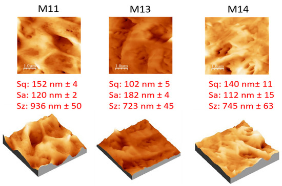
Figure 12.
AFM images, with corresponding 3D views, and roughness parameters of M11, M13 and M14 membranes.
The different structures exhibited by the membranes prepared with ethanol and isopropanol in the coagulation bath resulted in an improvement in their stiffness (Young’s Modulus) accompanied by a decrease in their elasticity (Figure 13).
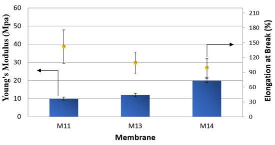
Figure 13.
Mechanical properties of M11, M13 and M14 membranes.
3.4. Water Permeability, Rejection Tests and Comparison of the Results with the Literature
The performance of all of the membranes prepared at the intermediate exposure time to humidity of 2.5 min and using water as a coagulation bath (M2, M5, M8 and M11) were studied in terms of hydraulic permeability and rejection to MB dye.
As can be seen from Figure 14, the water permeability of each membrane was in line with pore size data. M2 and M5 membranes, exhibiting a UF pore size of 0.05 µm, showed the same values of water permeability (about 3200 L/m2 h bar). As the pore size further increased in MF range, with M8 and M11 membranes, the water permeability also increased, reaching a value of almost 40,000 L/m2 h bar. MB rejection (Figure 14) reached the maximum with the M2 membrane (83%), while it decreased with the increase in pore size (72% for M11 membrane).
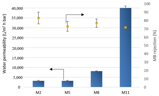
Figure 14.
Water permeability and MB rejection of selected membranes.
Table 7 summarizes and compares, in terms of dope composition, preparation procedure and performance, the results obtained in this work with the data of PVDF-based membranes reported in the literature. Until now, the use of the green solvent PolarClean was mainly limited to the preparation of PVDF membranes in hollow fiber configuration using the NIPS/TIPS technique [18,52,53]. In all cases, the temperature required to solubilize the polymer was above 130 °C. To the best of our knowledge there is just one article reporting the preparation of PVDF-based membranes in PolarClean in flat sheet configuration, but using the TIPS technique (140 °C) [17]. In our approach, the use of PVDF-HFP allowed us to operate at a milder temperature (80 °C) using the VIPS/NIPS preparation method. The additives employed are generally represented by PVP and PEG, even if some authors explored the use of Pluronic (PMMA) [18] and TiO2 [52]. Other green or more sustainable solvents, such as triethyl phosphate (TEP) [54], Tamisolve NxG [4], γ-Butyrolactone [55] and propylene carbonate [55] have been used for the preparation of PVDF membranes by NIPS and TIPS. Besides the greener alternatives, traditional harmful solvents, such as DMF and NMP, have been widely investigated for the fabrication of PVDF membranes [56,57]. The performance of the produced membranes is wide and variable and mainly related to their properties (e.g., pore size, porosity, morphology).

Table 7.
Dope composition, preparation procedure and performance of PVDF-based membranes prepared using PolarClean and other green and traditional solvents.
The performance of the membranes prepared with PolarClean in this work are comparable, or even better, with those of PVDF membranes prepared with other green or traditional solvents reported in the literature. Russo et al. [4], for instance, prepared PVDF membranes (10 wt% of polymer) using Tamisolve® NxG as a more sustainable solvent. The obtained UF membranes (pore size 0.06 μm) showed a water permeability of 88 L/m2 h bar and an MB rejection of 79%. Buonomenna et al. [56] evaluated the performance of PVDF membranes (15 wt% of polymer), prepared in DMF, reaching an MB rejection of about 40% with a water permeability of 5 L/m2 h bar. PVDF membrane performance was drastically improved (MB rejection of 100%) when the surface of the membrane was modified by plasma treatment introducing amino groups on the membrane. UF PVDF membranes (20 wt% of polymer), prepared in NMP, were also employed by Tran et al. [57] for the rejection study of various dyes. MB was rejected at almost 50% with a membrane permeance of about 131 L/m2 h MPa.
4. Conclusions
The transition towards more sustainable production in membrane preparation passes through the replacement of traditional harmful solvents with green alternatives. However, production processes with green solvents need to be improved and optimized.
In this work, the fluoropolymer PVDF-HFP was employed for the first time for the preparation of membranes by the VIPS/NIPS technique using PolarClean as a green solvent. The use of PVDF-HFP allowed us to operate at a milder dope solution temperatures (80 °C) with respect to PVDF/PolarClean solutions prepared by TIPS, making the process more affordable on a larger scale. PolarClean was demonstrated to be a valid candidate for the replacement of NMP in the preparation of porous membranes. When prepared under the same conditions, membranes obtained with both solvents showed comparable properties (e.g., pore size) and performance (e.g., water permeability). The exposure time to humidity resulted to play a crucial role in tuning membrane morphology and pore size, above all when pore forming additives (PVP and PEG) were employed. As expected, the addition of additives promoted the formation of membranes with a larger pore size and slightly lower mechanical properties. The addition of the polymer S-PES caused a general increase in membrane pore size and membrane permeability placing the prepared membranes in the MF range. The influence of the different additives on membrane wettability was negligible due to their removal during membrane rinsing with hot water (for PVP and PEG) and due to the low concentration in the dope solution (for S-PES). The wettability was, therefore, mainly governed by the polymer nature and surface roughness.
The addition of alcohols (ethanol and isopropanol) in the aqueous coagulation bath slowed down the precipitation process of the cast films leading to the formation of membranes with a lower pore size. The prepared membranes resulted in being very permeable to water (water permeability higher than 3200 L/m2 h bar) with a good rejection of MB (varying from 72 to 89%), which was dependent on their pore size.
The results stemming from this work highlight the potential application of the more sustainable PVDF-HFP-produced membranes in the water treatment sector. Moreover, the simple preparation approach method would allow a better exploitation of the green solvent PolarClean for the production of PVDF-HFP membranes on a larger scale.
Author Contributions
Conceptualization, I.K. and A.F.; validation, F.G. and A.F., investigation, F.R., C.U., B.S. and F.G.; resources, A.F.; data curation, F.R., C.U. and F.G.; writing—original draft preparation, F.G.; writing—review and editing, F.G. and A.F.; supervision, I.K. and A.F. All authors have read and agreed to the published version of the manuscript.
Funding
This research received no external funding.
Institutional Review Board Statement
Not applicable.
Informed Consent Statement
Not applicable.
Data Availability Statement
The corresponding authors can be contacted for further information and access to raw data.
Acknowledgments
This work has been developed within the project TARANTO (Tecnologie e processi per l’Abbattimento di inquinanti e la bonifica di siti contaminate con Recupero di mAterie prime e produzione di energia TOtally green) project code ARS01_00637, supported by MIUR within the framework PON 2014–2020–Ricerca e Innovazione.
Conflicts of Interest
The authors declare no conflict of interest.
References
- Shao, L.; Low, B.T.; Chung, T.-S.; Greenberg, A.R. Polymeric membranes for the hydrogen economy: Contemporary approaches and prospects for the future. J. Membr. Sci. 2009, 327, 18–31. [Google Scholar] [CrossRef]
- Ismail, N.; Venault, A.; Mikkola, J.-P.; Bouyer, D.; Drioli, E.; Tavajohi Hassan Kiadeh, N. Investigating the potential of membranes formed by the vapor induced phase separation process. J. Membr. Sci. 2020, 597, 117601. [Google Scholar] [CrossRef]
- Yadav, P.; Ismail, N.; Essalhi, M.; Tysklind, M.; Athanassiadis, D.; Tavajohi, N. Assessment of the environmental impact of polymeric membrane production. J. Membr. Sci. 2021, 622, 118987. [Google Scholar] [CrossRef]
- Russo, F.; Marino, T.; Galiano, F.; Gzara, L.; Gordano, A.; Organji, H.; Figoli, A. Tamisolve® NxG as an Alternative Non-Toxic Solvent for the Preparation of Porous Poly (Vinylidene Fluoride) Membranes. Polymers 2021, 13, 2579. [Google Scholar] [CrossRef] [PubMed]
- European Chemicals Agency. How to Comply with REACH Restriction 71, Guideline for Users of NMP (1-Methyl-2-Pyrrolidone); European Chemicals Agency: Helsinki, Finland, 2019.
- Figoli, A.; Marino, T.; Simone, S.; Di Nicolò, E.; Li, X.-M.; He, T.; Tornaghi, S.; Drioli, E. Towards non-toxic solvents for membrane preparation: A review. Green Chem. 2014, 16, 4034. [Google Scholar] [CrossRef]
- Prézélus, F.; Chabni, D.; Barna, L.; Guigui, C.; Remigy, J.C. A metrics-based approach to preparing sustainable membranes: Application to ultrafiltration. Green Chem. 2019, 21, 4457–4469. [Google Scholar] [CrossRef] [Green Version]
- Galiano, F.; Ghanim, A.H.; Rashid, K.T.; Marino, T.; Simone, S.; Alsalhy, Q.F.; Figoli, A. Preparation and characterization of green polylactic acid (PLA) membranes for organic/organic separation by pervaporation. Clean Technol. Environ. Policy 2019, 21, 109–120. [Google Scholar] [CrossRef]
- Marino, T.; Russo, F.; Figoli, A. The Formation of Polyvinylidene Fluoride Membranes with Tailored Properties via Vapour/Non-Solvent Induced Phase Separation. Membranes 2018, 8, 71. [Google Scholar] [CrossRef] [Green Version]
- Russo, F.; Ursino, C.; Avruscio, E.; Desiderio, G.; Perrone, A.; Santoro, S.; Galiano, F.; Figoli, A. Innovative Poly (Vinylidene Fluoride) (PVDF) Electrospun Nanofiber Membrane Preparation Using DMSO as a Low Toxicity Solvent. Membranes 2020, 10, 36. [Google Scholar] [CrossRef] [Green Version]
- Kim, D.; Vovusha, H.; Schwingenschlögl, U.; Nunes, S.P. Polyethersulfone flat sheet and hollow fiber membranes from solutions in ionic liquids. J. Membr. Sci. 2017, 539, 161–171. [Google Scholar] [CrossRef] [Green Version]
- Russo, F.; Galiano, F.; Pedace, F.; Aricò, F.; Figoli, A. Dimethyl Isosorbide As a Green Solvent for Sustainable Ultrafiltration and Microfiltration Membrane Preparation. ACS Sustain. Chem. Eng. 2020, 8, 659–668. [Google Scholar] [CrossRef]
- Aricò, F.; Tundo, P. Isosorbide and dimethyl carbonate: A green match. Beilstein J. Org. Chem. 2016, 12, 2256–2266. [Google Scholar] [CrossRef] [Green Version]
- Marino, T.; Galiano, F.; Molino, A.; Figoli, A. New frontiers in sustainable membrane preparation: CyreneTM as green bioderived solvent. J. Membr. Sci. 2019, 580, 224–234. [Google Scholar] [CrossRef]
- Marino, T.; Blasi, E.; Tornaghi, S.; Di Nicolò, E.; Figoli, A. Polyethersulfone membranes prepared with Rhodiasolv®Polarclean as water soluble green solvent. J. Membr. Sci. 2018, 549, 192–204. [Google Scholar] [CrossRef]
- Ursino, C.; Russo, F.; Ferrari, R.M.; De Santo, M.P.; Di Nicolò, E.; He, T.; Galiano, F.; Figoli, A. Polyethersulfone hollow fiber membranes prepared with Polarclean® as a more sustainable solvent. J. Membr. Sci. 2020, 608, 118216. [Google Scholar] [CrossRef]
- Jung, J.T.; Kim, J.F.; Wang, H.H.; di Nicolo, E.; Drioli, E.; Lee, Y.M. Understanding the non-solvent induced phase separation (NIPS) effect during the fabrication of microporous PVDF membranes via thermally induced phase separation (TIPS). J. Membr. Sci. 2016, 514, 250–263. [Google Scholar] [CrossRef]
- Hassankiadeh, N.T.; Cui, Z.; Kim, J.H.; Shin, D.W.; Lee, S.Y.; Sanguineti, A.; Arcella, V.; Lee, Y.M.; Drioli, E. Microporous poly(vinylidene fluoride) hollow fiber membranes fabricated with PolarClean as water-soluble green diluent and additives. J. Membr. Sci. 2015, 479, 204–212. [Google Scholar] [CrossRef]
- García-Payo, M.C.; Essalhi, M.; Khayet, M. Effects of PVDF-HFP concentration on membrane distillation performance and structural morphology of hollow fiber membranes. J. Membr. Sci. 2010, 347, 209–219. [Google Scholar] [CrossRef]
- Lalia, B.S.; Guillen, E.; Arafat, H.A.; Hashaikeh, R. Nanocrystalline cellulose reinforced PVDF-HFP membranes for membrane distillation application. Desalination 2014, 332, 134–141. [Google Scholar] [CrossRef]
- Tian, X.; Jiang, X. Poly(vinylidene fluoride-co-hexafluoropropene) (PVDF-HFP) membranes for ethyl acetate removal from water. J. Hazard. Mater. 2008, 153, 128–135. [Google Scholar] [CrossRef]
- Pu, W.; He, X.; Wang, L.; Jiang, C.; Wan, C. Preparation of PVDF–HFP microporous membrane for Li-ion batteries by phase inversion. J. Membr. Sci. 2006, 272, 11–14. [Google Scholar] [CrossRef]
- Wongchitphimon, S.; Wang, R.; Jiraratananon, R. Surface modification of polyvinylidene fluoride-co-hexafluoropropylene (PVDF–HFP) hollow fiber membrane for membrane gas absorption. J. Membr. Sci. 2011, 381, 183–191. [Google Scholar] [CrossRef]
- Ahmed, F.E.; Lalia, B.S.; Hilal, N.; Hashaikeh, R. Underwater superoleophobic cellulose/electrospun PVDF–HFP membranes for efficient oil/water separation. Desalination 2014, 344, 48–54. [Google Scholar] [CrossRef]
- Rhodiasolv® PolarClean—Green solvent|Solvay. Available online: https://www.solvay.com/en/brands/rhodiasolv-polarclean (accessed on 1 September 2021).
- Clark, J.H.; Hunt, A.; Topi, C.; Paggiola, G.; Sherwood, J. An Appendix of Solvent Data Sheets in Sustainable Solvents: Perspectives from Research, Business and International Policy, Ch. 6; Royal Society of Chemistry: Cambdridge, UK, 2017; pp. 235–347. [Google Scholar]
- Prat, D.; Wells, A.; Hayler, J.; Sneddon, H.; McElroy, C.R.; Abou-Shehada, S.; Dunn, P.J. CHEM21 selection guide of classical- and less classical-solvents. Green Chem. 2016, 18, 288–296. [Google Scholar] [CrossRef] [Green Version]
- Russo, F.; Bulzomì, M.; Di Nicolò, E.; Ursino, C.; Figoli, A. Enhanced anti-fouling behavior and performance of pes membrane by uv treatment. Processes 2021, 9, 246. [Google Scholar] [CrossRef]
- Alder, C.M.; Hayler, J.D.; Henderson, R.K.; Redman, A.M.; Shukla, L.; Shuster, L.E.; Sneddon, H.F. Updating and further expanding GSK’s solvent sustainability guide. Green Chem. 2016, 18, 3879–3890. [Google Scholar] [CrossRef]
- Adamska, K.; Voelkel, A. Hansen solubility parameters for polyethylene glycols by inverse gas chromatography. J. Chromatogr. A 2006, 1132, 260–267. [Google Scholar] [CrossRef]
- Hansen, C.M. Hansen Solubility Parameters: A User’s Handbook, 2nd ed.; CRC Press: London, UK, 2007. [Google Scholar]
- Huang, W.; Wang, H.; Li, C.; Wen, T.; Xu, J.; Ouyang, J.; Zhang, C. Measurement and correlation of solubility, Hansen solubility parameters and thermodynamic behavior of Clozapine in eleven mono-solvents. J. Mol. Liq. 2021, 333, 115894. [Google Scholar] [CrossRef]
- Wang, R.; Shi, L.; Tang, C.Y.; Chou, S.; Qiu, C.; Fane, A.G. Characterization of novel forward osmosis hollow fiber membranes. J. Membr. Sci. 2010, 355, 158–167. [Google Scholar] [CrossRef]
- Wijmans, J.G.; Kant, J.; Mulder, M.H.V.; Smolders, C.A. Phase separation phenomena in solutions of polysulfone in mixtures of a solvent and a nonsolvent: Relationship with membrane formation. Polymer 1985, 26, 1539–1545. [Google Scholar] [CrossRef] [Green Version]
- Shi, L.; Wang, R.; Cao, Y. Effect of the rheology of poly(vinylidene fluoride-co-hexafluropropylene) (PVDF–HFP) dope solutions on the formation of microporous hollow fibers used as membrane contactors. J. Membr. Sci. 2009, 344, 112–122. [Google Scholar] [CrossRef]
- Russo, F.; Castro-Muñoz, R.; Galiano, F.; Figoli, A. Unprecedented preparation of porous Matrimid® 5218 membranes. J. Membr. Sci. 2019, 585, 166–174. [Google Scholar] [CrossRef]
- Cassie, A.B.D.; Baxter, S. Wettability of porous surfaces. Trans. Faraday Soc. 1944, 40, 546. [Google Scholar] [CrossRef]
- Randová, A.; Bartovská, L.; Morávek, P.; Matějka, P.; Novotná, M.; Matějková, S.; Drioli, E.; Figoli, A.; Lanč, M.; Friess, K. A fundamental study of the physicochemical properties of Rhodiasolv®Polarclean: A promising alternative to common and hazardous solvents. J. Mol. Liq. 2016, 224, 1163–1171. [Google Scholar] [CrossRef]
- Mulder, M.H.V.; Hendrikman, J.O.; Wijmans, J.G.; Smolders, C.A. A rationale for the preparation of asymmetric pervaporation membranes. J. Appl. Polym. Sci. 1985, 30, 2805–2820. [Google Scholar] [CrossRef] [Green Version]
- Hou, T.P.; Dong, S.H.; Zheng, L.Y. The study of mechanism of organic additives action in the polysulfone membrane casting solution. Desalination 1991, 83, 343–360. [Google Scholar] [CrossRef]
- Gzara, L.; Rehan, Z.A.; Simone, S.; Galiano, F.; Hassankiadeh, N.T.; Al-Sharif, S.F.; Figoli, A.; Drioli, E. Tailoring PES membrane morphology and properties via selected preparation parameters. J. Polym. Eng. 2017, 37, 69–81. [Google Scholar] [CrossRef]
- Wang, X.; Xiao, C.; Liu, H.; Huang, Q.; Fu, H. Fabrication and properties of PVDF and PVDF-HFP microfiltration membranes. J. Appl. Polym. Sci. 2018, 135, 46711. [Google Scholar] [CrossRef]
- Cui, Z.; Hassankiadeh, N.T.; Zhuang, Y.; Drioli, E.; Lee, Y.M. Crystalline polymorphism in poly(vinylidenefluoride) membranes. Prog. Polym. Sci. 2015, 51, 94–126. [Google Scholar] [CrossRef]
- Meringolo, C.; Mastropietro, T.F.; Poerio, T.; Fontananova, E.; De Filpo, G.; Curcio, E.; Di Profio, G. Tailoring PVDF Membranes Surface Topography and Hydrophobicity by a Sustainable Two-Steps Phase Separation Process. ACS Sustain. Chem. Eng. 2018, 6, 10069–10077. [Google Scholar] [CrossRef]
- Smolders, C.A.; Reuvers, A.J.; Boom, R.M.; Wienk, I.M. Microstructures in phase-inversion membranes. Part 1. Formation of macrovoids. J. Membr. Sci. 1992, 73, 259–275. [Google Scholar] [CrossRef] [Green Version]
- Chou, W.-L.; Yu, D.-G.; Yang, M.-C.; Jou, C.-H. Effect of molecular weight and concentration of PEG additives on morphology and permeation performance of cellulose acetate hollow fibers. Sep. Purif. Technol. 2007, 57, 209–219. [Google Scholar] [CrossRef]
- Susanto, H.; Stahra, N.; Ulbricht, M. High performance polyethersulfone microfiltration membranes having high flux and stable hydrophilic property. J. Membr. Sci. 2009. [Google Scholar] [CrossRef]
- Rahimpour, A.; Madaeni, S.S.; Ghorbani, S.; Shockravi, A.; Mansourpanah, Y. The influence of sulfonated polyethersulfone (SPES) on surface nano-morphology and performance of polyethersulfone (PES) membrane. Appl. Surf. Sci. 2010, 256, 1825–1831. [Google Scholar] [CrossRef]
- Rahimpour, A.; Jahanshahi, M.; Rajaeian, B.; Rahimnejad, M. TiO2 entrapped nano-composite PVDF/SPES membranes: Preparation, characterization, antifouling and antibacterial properties. Desalination 2011, 278, 343–353. [Google Scholar] [CrossRef]
- Deshmukh, S.P.; Li, K. Effect of ethanol composition in water coagulation bath on morphology of PVDF hollow fibre membranes. J. Membr. Sci. 1998, 150, 75–85. [Google Scholar] [CrossRef]
- Fadhil, S.; Marino, T.; Makki, H.F.; Alsalhy, Q.F.; Blefari, S.; Macedonio, F.; Di Nicolò, E.; Giorno, L.; Drioli, E.; Figoli, A. Novel PVDF-HFP flat sheet membranes prepared by triethyl phosphate (TEP) solvent for direct contact membrane distillation. Chem. Eng. Process. Process. Intensif. 2016, 102, 16–26. [Google Scholar] [CrossRef]
- Zou, D.; Jeon, S.M.; Kim, H.W.; Bae, J.Y.; Lee, Y.M. In-situ grown inorganic layer coated PVDF/PSF composite hollow fiber membranes with enhanced separation performance. J. Membr. Sci. 2021, 637, 119632. [Google Scholar] [CrossRef]
- Jung, J.T.; Wang, H.H.; Kim, J.F.; Lee, J.; Kim, J.S.; Drioli, E.; Lee, Y.M. Tailoring nonsolvent-thermally induced phase separation (N-TIPS) effect using triple spinneret to fabricate high performance PVDF hollow fiber membranes. J. Membr. Sci. 2018, 559, 117–126. [Google Scholar] [CrossRef]
- Alyarnezhad, S.; Marino, T.; Parsa, J.B.; Galiano, F.; Ursino, C.; Garcìa, H.; Puche, M.; Figoli, A. Polyvinylidene Fluoride-Graphene Oxide Membranes for Dye Removal under Visible Light Irradiation. Polymers 2020, 12, 1509. [Google Scholar] [CrossRef] [PubMed]
- Su, Y.; Chen, C.; Li, Y.; Li, J. PVDF membrane formation via thermally induced phase separation. J. Macromol. Sci. A Pure Appl. Chem. 2007, 44, 99–104. [Google Scholar] [CrossRef]
- Buonomenna, M.G.; Lopez, L.C.; Favia, P.; D’Agostino, R.; Gordano, A.; Drioli, E. New PVDF membranes: The effect of plasma surface modification on retention in nanofiltration of aqueous solution containing organic compounds. Water Res. 2007, 41, 4309–4316. [Google Scholar] [CrossRef] [PubMed]
- Van Tran, T.T.; Kumar, S.R.; Lue, S.J. Separation mechanisms of binary dye mixtures using a PVDF ultrafiltration membrane: Donnan effect and intermolecular interaction. J. Membr. Sci. 2019, 575, 38–49. [Google Scholar] [CrossRef]
Publisher’s Note: MDPI stays neutral with regard to jurisdictional claims in published maps and institutional affiliations. |
© 2021 by the authors. Licensee MDPI, Basel, Switzerland. This article is an open access article distributed under the terms and conditions of the Creative Commons Attribution (CC BY) license (https://creativecommons.org/licenses/by/4.0/).