A Simple Strategy to Reduce the NDZ Caused by the Parallel Operation of DER-Inverters

 ,
,  ,
,  , ,
, ,
Abstract
1. Introduction
2. Description of System Under Study
3. Proposed Modification and Description of the Anti-Islanding Technique in reference [2]
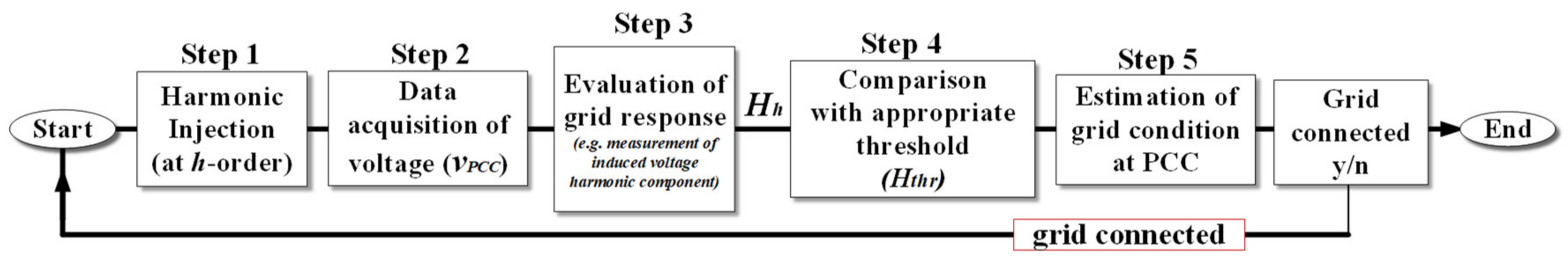
3.1. Description of the Anti-Islanding Technique That Has Been Proposed in reference [2]
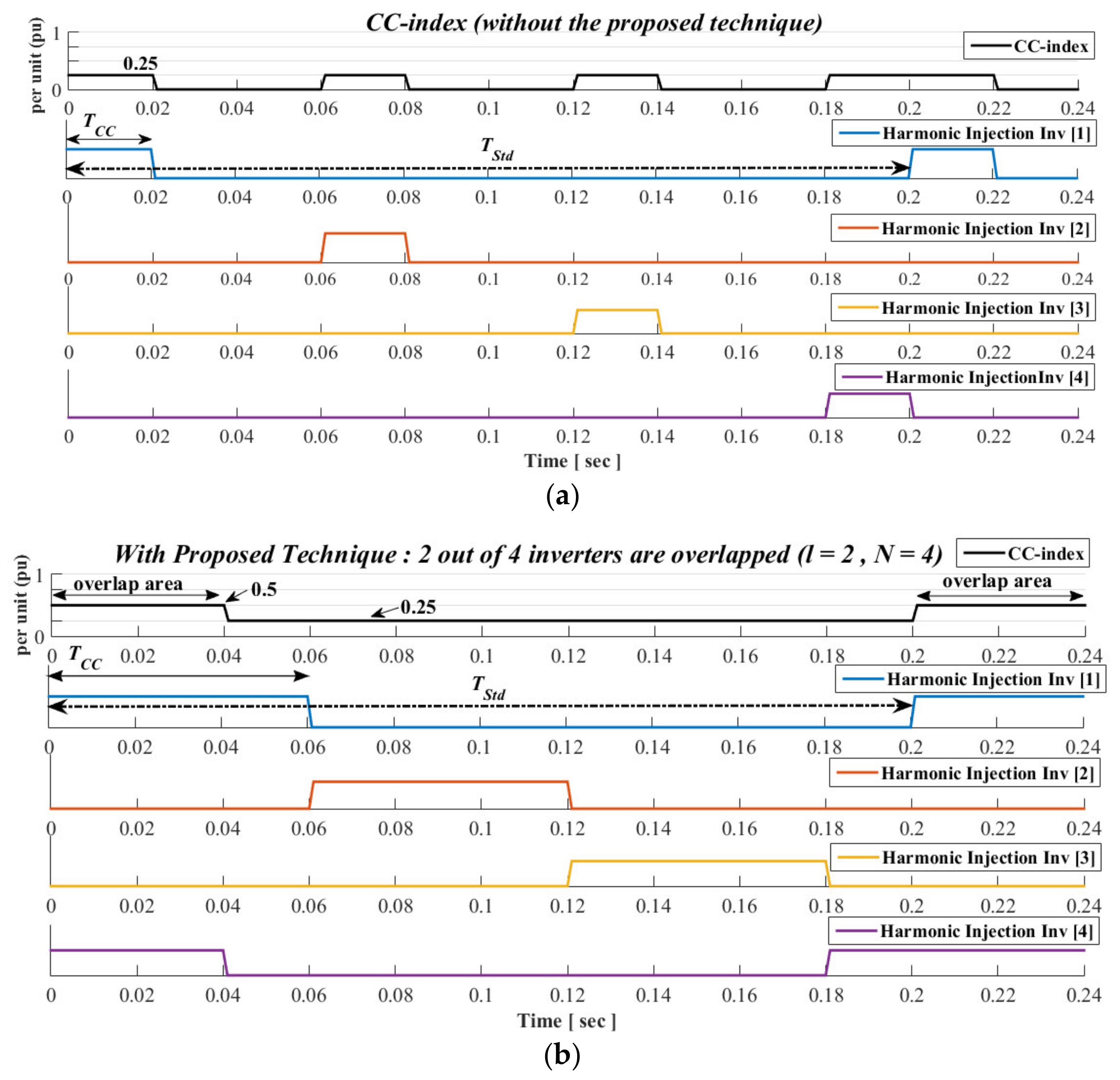
3.2. Description of the Issue That Arises by the Parallel Operation of Multiple Grid-Tied Inverters
3.3. Description of the Proposed Modified Anti-Islanding Scheme for N Grid-Tied Inverters
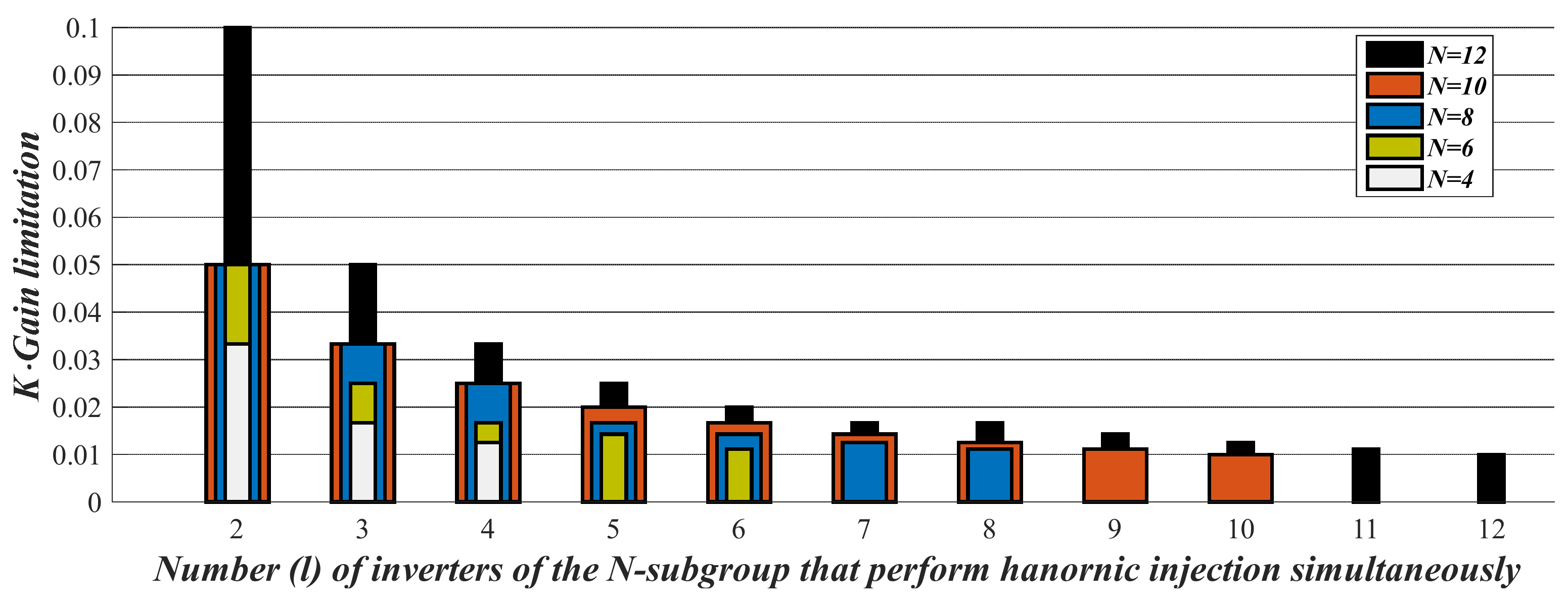
3.4. Discussion on the Limitations of the Proposed Modification
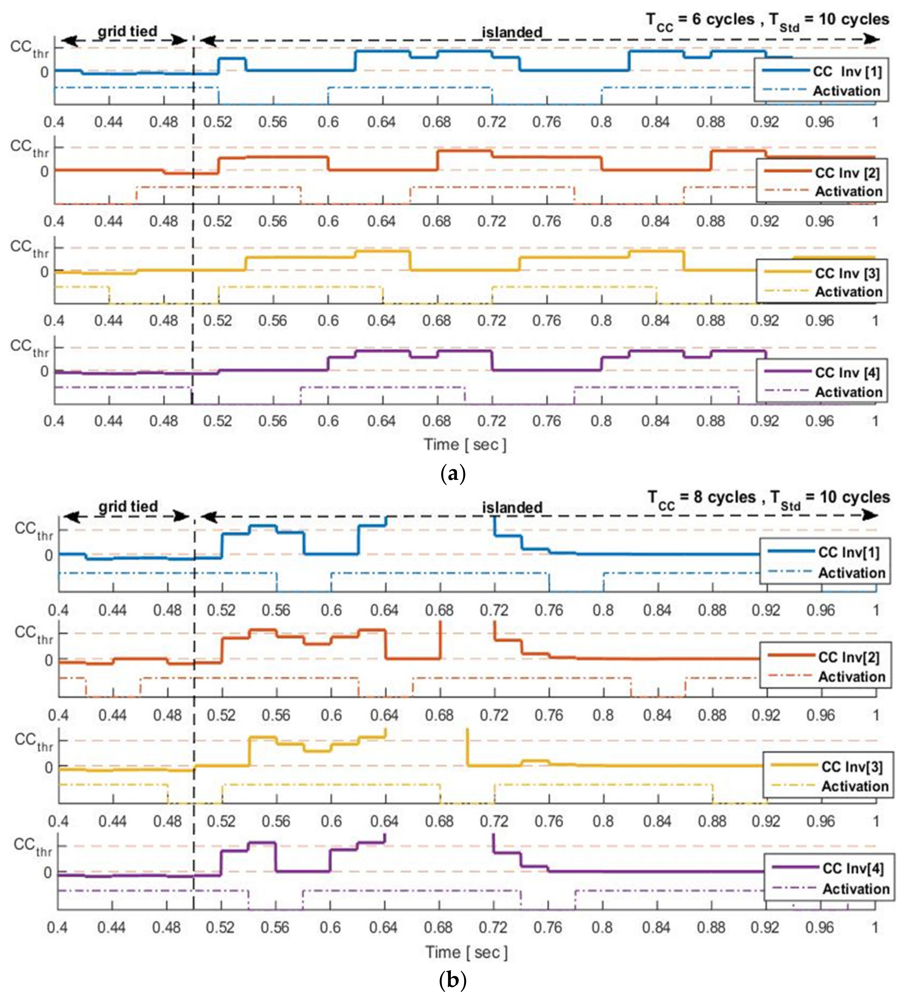
4. Simulation Results
4.1. Case I, Grid-Tied CSI Inverter Operates at Nominal Power While l Varies
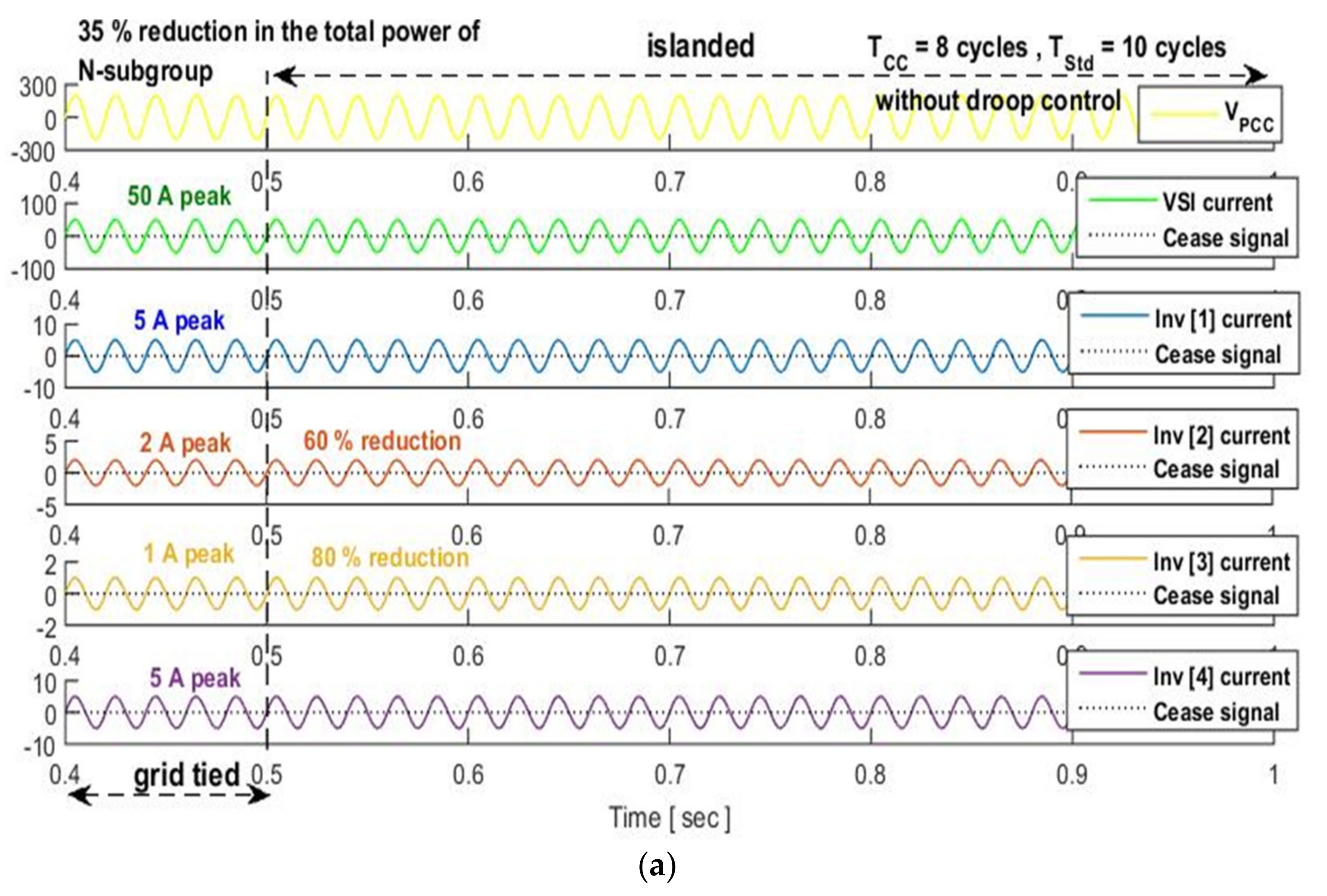
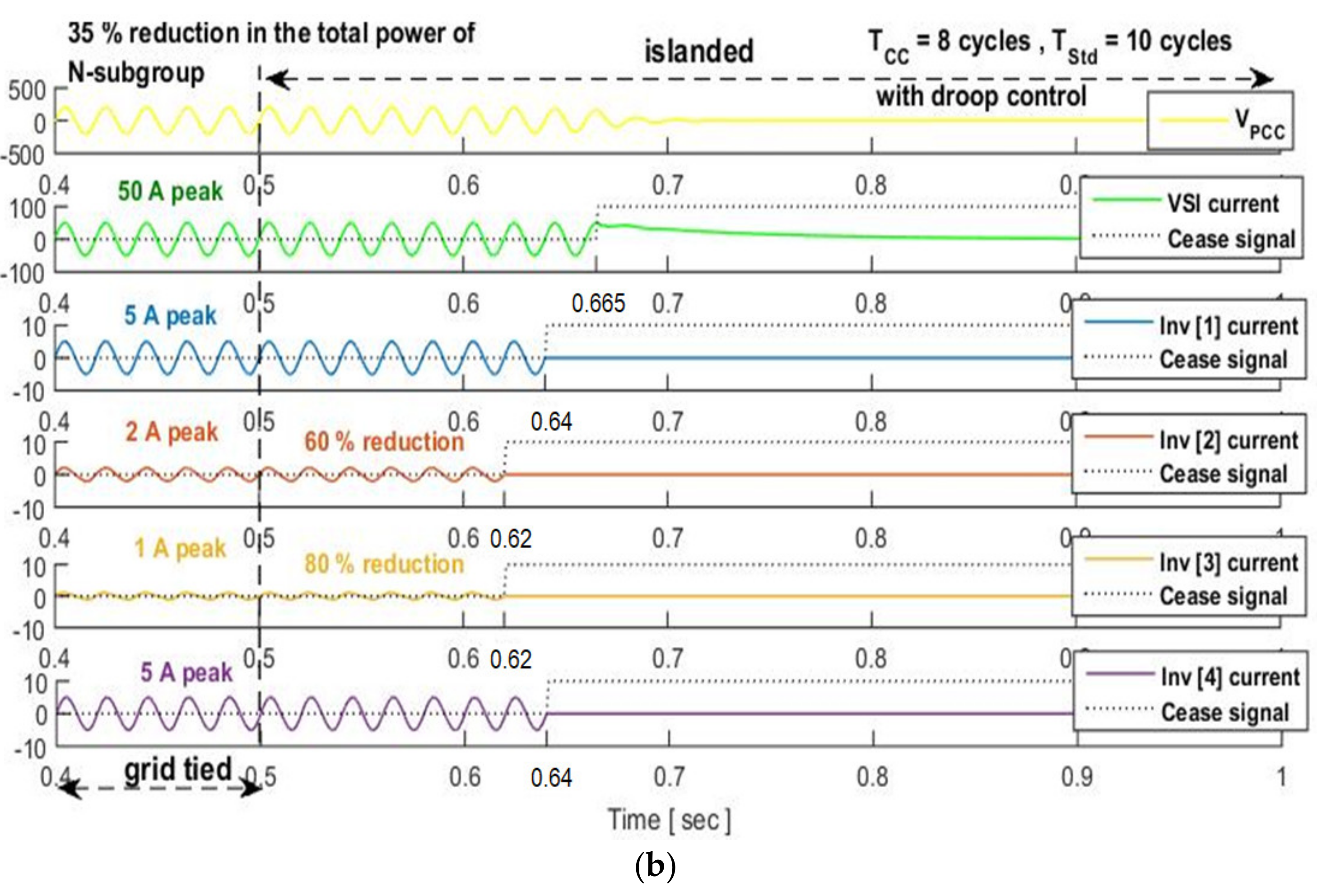
4.2. For Case II, l is Equal to 4, while the Power of CSI Is Reduced to 60%
5. Experimental Results
6. Conclusions
Author Contributions
Funding
Conflicts of Interest
Nomenclature
| PV | Photovoltaic generator |
| PCC | Point of Common Coupling |
| NDZ | Non- detection zone |
| FDZ | Fault-detection zone |
| THDi | Total harmonic distortion of the inverter output injected current |
| DPF | Displacement power factor |
| MPPT | Maximum power point tracking |
| PLL | Phase locked loop |
| CSI, VSI | Current and Voltage Source Inverter |
| DER-CSI | Distributed energy resource current source inverter |
| CC | Cross-correlation |
| N | Initial number of inverters that are using the proposed anti-islanding technique |
| M | Additional number of inverters that can be installed at PCC without compromising the effectiveness of the proposed anti-islanding technique |
| l | Minimum number of the inverters of the N-subgroup, which perform the harmonic injection, and are required to in order to achieve the desired overlap |
| m | Number of M-subgroup inverters that may (or may not) use the proposed anti-islanding technique |
| DCM | Discontinuous conduction mode |
| REP | Consecutive times that the anti-islanding threshold must be surpassed before the identification of islanded-operation |
| RL, CL, LL | Equivalent resistance, capacitance, and inductance of the islanded network |
| SSC | Short circuit power at PCC (VA) |
| ωb. fb, Tb | Utility base angular frequency, utility base frequency, and utility base period |
| Xg, Rg | Equivalent grid internal impedance (at base angular frequency ωb) and resistance at PCC |
| QL | Quality factor of islanded network |
| i | Islanded (i = isl) or grid-tied (i = grid) operation |
| Hi,h, ei,h | Index and evaluation function of the anti-islanding technique |
| VPCC, | Instantaneous and peak value of PCC voltage |
| Peak value of the h-order harmonic component of PCC voltage in islanded or grid-tied operation; it refers to the component that is induced by the islanding-scheme and not to the pre-existing harmonics of the grid-voltage | |
| Peak value of the fundamental component of PCC voltage | |
| Peak value of the harmonic current component which is injected by inverter (imposed by the anti-islanding technique), in grid-tied or islanded operation | |
| K | Rated ratio of the fundamental-harmonic current components of the inverter |
| K* | Actual value of K (activated during the droop control mode) |
| Gaini | Inverter gain in in grid-tied or islanded operation |
| TStd, TCC | Periodicity and duration of the harmonic injection |
| Zi,h | Impedance at the output stage of the inverter (at h-order), in grid-tied or islanded operation |
| ζi,h | = |Ζgrid/isl,h|/RL |
| Peak value of the reference that is used in the proposed scheme [2] | |
| S | Number of samples that is used to calculate the CCindex according to (3) |
| ΔφCC,i | Phase angle between and the reference signal |
| CCindex | Cross-correlation index |
| CCgrid, CCisl | Cross-correlation sequence index of the PCC voltage during the grid-tied operation or islanded operation |
| CCgridmax | Maximum value of CCgrid [2] |
| CCilsmin | Minimum value of CCisl, [2] |
| CCthr | Threshold-value that is used in the proposed method (CC>CCthr for islanded operation) |
| W% | Margin between the islanded and grid-operation (as a percentage) |
| PN[n] | Nominal power of each inverter of the N-subgroup |
| PN*[n] | Actual power of each N-subgroup inverter |
| PNtot | Total nominal power of N-subgroup |
| PM[m] | Nominal power of each inverter of the M-subgroup |
| PMtot | Total nominal power of M-subgroup |
| Ptot | Total nominal power of the installation (including both the N-subgroup and the M-subgroup inverters) |
| PL | = PNtot/SSC, penetration level of PV-units that are connected at the same node and utilize the proposed anti-islanding method |
| UF | = PMtot/PNtot, upgrade factor of the installation |
| U/O-V&F | Under/Over Voltage & Frequency, it is a widely used passive anti-islanding technique |
References
- Yang, Y.; Enjeti, P.; Wang, H.; Blaabjerg, F. Wide-scale adoption of photovoltaic energy: Grid code modifications are explored in the distribution grid. IEEE Ind. Appl. Mag. 2015, 21, 21–31. [Google Scholar] [CrossRef]
- Voglitsis, D.; Papanikolaou, N.; Kyritsis, A. Active cross-correlation anti-islanding scheme for PV module-integrated converters in the prospect of high penetration levels and weak grid conditions. IEEE Trans. Power Electron. 2018, 34, 2258–2274. [Google Scholar] [CrossRef]
- Voglitsis, D.; Papanikolaou, N.; Kyritsis, A. Incorporation of harmonic injection in an interleaved flyback inverter for the implementation of an active anti-islanding technique. IEEE Trans. Power Electron. 2016, 32, 8526–8543. [Google Scholar] [CrossRef]
- Asiminoaei, L.; Teodorescu, R.; Blaabjerg, F.; Borup, U. A digital controlled PV-inverter with grid impedance estimation for ENS detection’. IEEE Trans. Power Electron. 2005, 20, 1480–1490. [Google Scholar] [CrossRef]
- Byung-Gyu, Y.; Matsui, M.; Gwon-Jong, Y. A correlation-based islanding-detection method using current-magnitude disturbance for PV system. IEEE Trans. Ind. Electron. 2019, 58, 2935–2943. [Google Scholar]
- Bae, B.Y.; Jeong, J.K.; Lee, J.H.; Han, B.M. Islanding detection method for inverter-based distributed generation systems using a signal cross-correlation scheme. J. Power Electron. 2010, 10, 762–768. [Google Scholar] [CrossRef]
- Kim, J.H.; Kim, J.G.; Ji, Y.H.; Jung, Y.C.; Won, C.Y. An islanding detection method for a grid-tied system based on the Goertzel algorithm. IEEE Trans. Power Electron. 2010, 26, 1049–1055. [Google Scholar] [CrossRef]
- Voglitsis, D.; Valsamas, F.; Rigogiannis, N.; Papanikolaou, N.; Kyritsis, A. Comparative study of active anti-islanding schemes compatible to MICs in the prospect of high penetration levels and weak grid conditions. IET Gener. Transm. Distrib. 2018, 12, 4589–4596. [Google Scholar]
- Voglitsis, D.; Valsamas, F.; Rigogiannis, N.; Papanikolaou, N.P. On harmonic injection anti-islanding techniques under the operation of multiple DER-inverters. IEEE Trans. Energy Convers. 2018, 34, 455–467. [Google Scholar] [CrossRef]
- IEEE. IEEE Standard for Interconnection and Interoperability of Distributed Energy Resources with Associated Electric Power Systems Interfaces; IEEE Standard 1547; IEEE: Piscataway, NJ, USA, 2018. [Google Scholar]
- Tsimtsios, A.; Voglitsis, D.; Perpinias, I.; Korkas, C.; Papanikolaou, N. On the conflict between lvrt and line protection in LV distribution systems with PVs: A current-limitation-based solution. Energies 2019, 12, 2909. [Google Scholar] [CrossRef]
- Kyritsis, A.; Voglitsis, D.; Papanikolaou, N.P.; Tselepis, S.; Christodoulou, C.; Gonos, I.; Kalogirou, S.A. Evolution of PV systems in Greece and review of applicable solutions for higher penetration levels. Renew. Energy 2017, 109, 487–499. [Google Scholar] [CrossRef]
- Xue, Y.; Chang, L.; Kjær, S.B.; Bordonau, J.; Shimizu, T. Topologies of single-phase inverters for small distributed power generators: An overview. IEEE Trans. Power Electron. 2004, 19, 1305–1314. [Google Scholar] [CrossRef]
- Li, Q.; Wolfs, P. A review of the single phase photovoltaic module integrated converter topologies with three different DC link configurations. IEEE Trans. Power Electron. 2008, 23, 1320–1333. [Google Scholar]
- IEEE. IEEE Recommended Practice for Utility Interface of Photovoltaic (PV) Systems; IEEE Standard 929–2000; IEEE: Piscataway, NJ, USA, 2000. [Google Scholar]
- IEEE. IEEE Standard Conformance Test Procedures for Equipment Interconnecting Distributed Resources with Electric Power Systems; IEEE Standard 1547.1–2005; IEEE: Piscataway, NJ, USA, 2005. [Google Scholar]


| Electrical Quantity/Parameters | Value |
|---|---|
| VPCC, fb | 200 V (peak), 50 Hz |
| Xg/Rg | 1 |
| QLmax | 2.5 |
| SSC | 50 kVA |
| PL (it refers to the initial substation, PNtot) | 4% |
| PMtot; PN[n]; PNtot; N | 5 kW; 500 W; 2 kW; 4 |
| K; REP | 0.5%, 2 |
| TCC;TStd | 6 or 8; 10 cycles |
| W(%); UF; | 25; 2.5 |
| CCislmin*; CCgridmax*; CCthr* | 0.2577; 0; 0.064 |
| PCC-voltage (%) range for the U/O-V&F activation | 85%, 110% |
| Electrical Quantity/Parameters | Value |
| Inverters Rating | Vdc = 25 − 50 V; Vac_rms = 133 V |
| Primary inductance; Turns ratio | 30 μH; 1 |
| RL; LL; CL; QL | 235 Ω; 290 mH; 35 nF; 2.5 |
| Xg/Rg; PL | 1; 17% |
| Lg; Rg | 28.9 mH; 9.1 Ω |
| N | 2 |
| PNtot (PN[1] = PN[2]) | 75 W |
| CCisl-min; CCgrid-max; CCthr | 0.5; 0.14; 0.47 |
| TStd; TCC | 0.2 s (10 cycles); 0.02 s (1 cycle for the conventional method) or 0.12 s (6 cycles for the proposed method) |
© 2020 by the authors. Licensee MDPI, Basel, Switzerland. This article is an open access article distributed under the terms and conditions of the Creative Commons Attribution (CC BY) license (http://creativecommons.org/licenses/by/4.0/).
Share and Cite
Voglitsis, D.; Valsamas, F.; Papanikolaou, N.; Tsimtsios, A.; Perpinias, I.; Korkas, C. A Simple Strategy to Reduce the NDZ Caused by the Parallel Operation of DER-Inverters. Clean Technol. 2020, 2, 17-31. https://doi.org/10.3390/cleantechnol2010002
Voglitsis D, Valsamas F, Papanikolaou N, Tsimtsios A, Perpinias I, Korkas C. A Simple Strategy to Reduce the NDZ Caused by the Parallel Operation of DER-Inverters. Clean Technologies. 2020; 2(1):17-31. https://doi.org/10.3390/cleantechnol2010002
Chicago/Turabian StyleVoglitsis, Dionisis, Fotis Valsamas, Nick Papanikolaou, Aristotelis Tsimtsios, Ioannis Perpinias, and Christos Korkas. 2020. "A Simple Strategy to Reduce the NDZ Caused by the Parallel Operation of DER-Inverters" Clean Technologies 2, no. 1: 17-31. https://doi.org/10.3390/cleantechnol2010002
APA StyleVoglitsis, D., Valsamas, F., Papanikolaou, N., Tsimtsios, A., Perpinias, I., & Korkas, C. (2020). A Simple Strategy to Reduce the NDZ Caused by the Parallel Operation of DER-Inverters. Clean Technologies, 2(1), 17-31. https://doi.org/10.3390/cleantechnol2010002