All articles published by MDPI are made immediately available worldwide under an open access license. No special
permission is required to reuse all or part of the article published by MDPI, including figures and tables. For
articles published under an open access Creative Common CC BY license, any part of the article may be reused without
permission provided that the original article is clearly cited. For more information, please refer to
https://www.mdpi.com/openaccess.
Feature papers represent the most advanced research with significant potential for high impact in the field. A Feature
Paper should be a substantial original Article that involves several techniques or approaches, provides an outlook for
future research directions and describes possible research applications.
Feature papers are submitted upon individual invitation or recommendation by the scientific editors and must receive
positive feedback from the reviewers.
Editor’s Choice articles are based on recommendations by the scientific editors of MDPI journals from around the world.
Editors select a small number of articles recently published in the journal that they believe will be particularly
interesting to readers, or important in the respective research area. The aim is to provide a snapshot of some of the
most exciting work published in the various research areas of the journal.
PBP-CMU Electron Linac Laboratory, Plasma and Beam Physics Research Facility, Department of Physics and Materials Science, Faculty of Science, Chiang Mai University, Chiang Mai 50200, Thailand
2
Ph. D. Program in Physics (International Program), Department of Physics and Materials Science, Faculty of Science, Chiang Mai University, Chiang Mai 50200, Thailand
3
Research Unit for Development and Utilization of Electron Linear Accelerator and Ultrafast Infrared/Terahertz Laser, Chiang Mai University, Chiang Mai 50200, Thailand
4
Thailand Center of Excellence in Physics, Ministry of Higher Education, Science, Research and Innovation, Bangkok 10400, Thailand
*
Author to whom correspondence should be addressed.
FLASH radiotherapy (FLASH-RT) is a cancer treatment delivering high-dose radiation within microseconds, reducing side-effects on healthy tissues. Implementing this technology at the PBP-CMU Electron Linac Laboratory poses challenges in ensuring radiation safety within a partially underground hall with thin walls and ceiling structures. This study develops a localized shielding design for electron beams (6–25 MeV) using the GEANT4 release 11.2.2 Monte Carlo simulation toolkit. A multilayer system of lead, iron, polyethylene, and concrete effectively attenuates X-rays, gamma-rays, and neutrons, achieving dose levels below 1 mSv/year for public areas and within 20 mSv/year for controlled areas, meeting international standards. The B-factor analysis highlights efficient low-energy gamma attenuation and thicker shielding requirements for high-energy rays. The design minimizes radiation leakage, ensuring safe operation for FLASH-RT while safeguarding personnel and the environment. Future work includes constructing and validating the system, with methodologies applicable to other electron beam facilities.
FLASH radiotherapy (FLASH-RT) is a revolutionary approach to cancer treatment that delivers high-dose radiation at significantly faster rates than than those used in conventional radiotherapy. This technique has attracted considerable attention due to its demonstrated ability to reduce side-effects on healthy tissue while treating tumors and cancer cells. Unlike traditional radiotherapy, which delivers radiation over extended periods, FLASH-RT achieves therapeutic effects within microseconds. This temporal distinction appears to elicit unique biological responses, referred to as the “FLASH effect”, which reduces damage to normal tissues. The precise mechanisms driving the FLASH effect remain an active area of research, with key parameters such as dose rate, total dose, and radiation pulse structure playing crucial roles [1,2]. In addition, oxygen concentration is a key parameter in the study of the mechanism of the FLASH effect. As oxygen levels decrease, they induce a protective hypoxic environment in normal cells [3]. Presently, several challenges remain in FLASH-RT experiments. Unlocking the full potential of FLASH-RT thus requires further experimental investigations and advancements in radiobiological understanding.
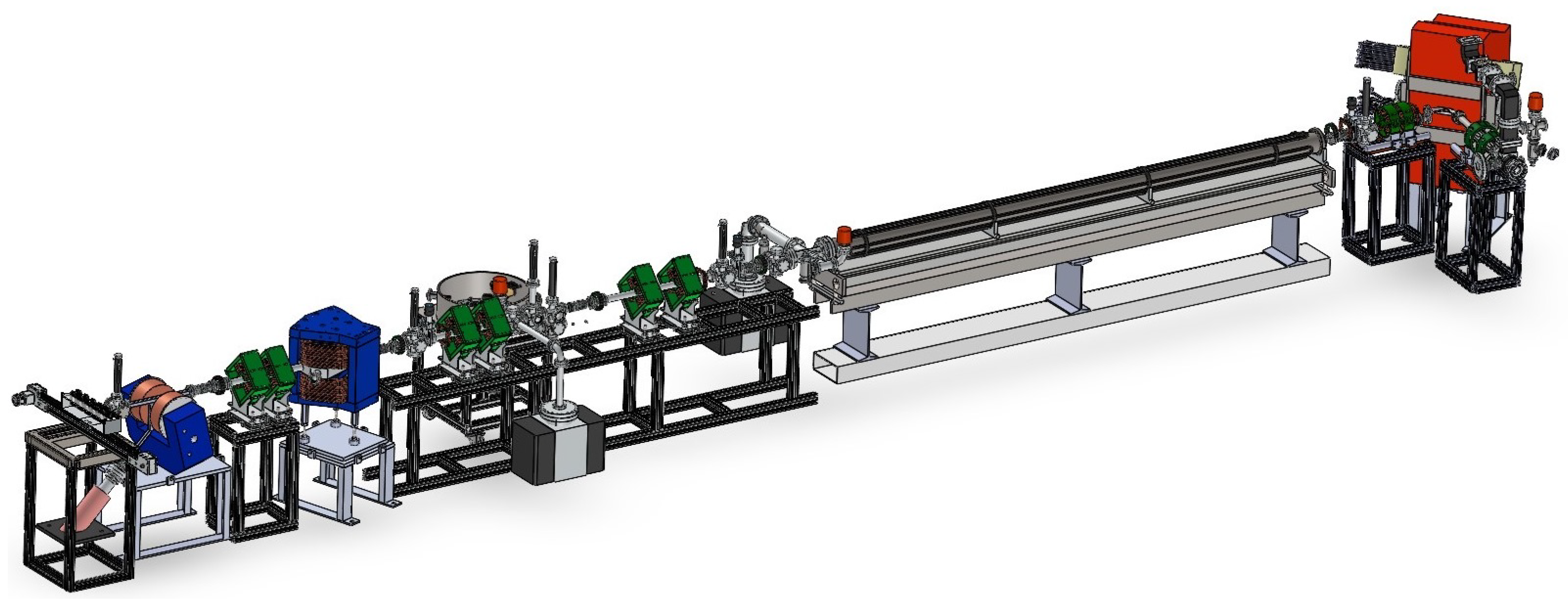
At the PBP-CMU Electron Linac Laboratory (PCELL), efforts are underway to contribute to this evolving field by producing electron beams specifically used for FLASH-RT experiments. These electron beams, with energies ranging from 6 to 25 MeV and pulse durations of the order of microseconds, provide an appropriate platform for probing the physical and biological underpinnings of the FLASH effect. The beams are generated and accelerated using an accelerator system that includes a thermionic radio-frequency (RF) gun [4], an alpha magnet [5], a linear accelerator (linac) structure, and a series of quadrupole and steering magnets for precise control of transverse beam properties. Downstream of this linac structure, a dedicated electron beam irradiation station is planned to facilitate experiments, as shown in Figure 1. However, the high-energy nature of these beams presents significant safety challenges, particularly in terms of secondary radiation production. High-energy electron beams interacting with matter produce intense X-rays and gamma-rays via bremsstrahlung processes. These secondary radiations can lead to ionization and excitation of surrounding materials, posing a potential risk to operators and the environment.
The primary challenge in implementing FLASH-RT at PCELL lies in ensuring robust radiation safety within the constraints of the existing facility. Unlike purpose-built underground installations, only half of the PCELL accelerator hall is located underground, as this hall was originally used to host a neutron generator, where skyshine X-ray or neutron radiation was not a concern. The hall features relatively thin walls (50–52 cm concrete) and a ceiling constructed from 1 cm of gypsum, making it vulnerable to radiation leakage. Initially, iron sheeting with a total thickness of 10 cm is installed at a height of 240 cm above the ground level of the accelerator hall. However, this alone is insufficient, necessitating the design of effective, localized radiation shielding for critical areas such as the beam dump and the irradiation station. Beyond safety, the shielding design must also accommodate the experimental setup, ensuring adequate space for researchers and equipment.
Radiation shielding has long been recognized as a critical aspect of safety in high-energy physics and medical applications. Foundational studies by Shultis and Faw [6] have provided significant insights into the interaction of neutron and gamma radiation with matter, emphasizing principles for optimizing material selection and structural design. Jaeger et al. [7] extended these principles to engineering contexts, offering guidance on the attenuation of photon radiation and the structural demands of shielding systems. Recent innovations, such as the multilayer shielding designs developed for FLASH-RT systems at the Stanford Linear Accelerator Center (SLAC) [8], demonstrated the effectiveness of advanced simulation techniques like Monte Carlo methods in reducing effective dose rates and ensuring compliance with radiation safety standards. They utilized multilayer shielding to enable compact self-shielding capable of managing both photon and neutron radiation. Monte Carlo simulations using FLUKA demonstrated that multilayered shielding achieved significantly lower doses compared to monolayer designs of the same thickness. These studies highlight the importance of optimizing shielding materials and designs to mitigate risks associated with the high-dose, high-energy radiation generated during FLASH-RT experiments.
This research employed the GEANT4 Monte Carlo simulation toolkit to address the safety challenges associated with FLASH-RT at PCELL. GEANT4 is a state-of-the-art platform for simulating the passage of particles through matter, making it particularly well suited for modeling the complex radiation environments generated by high-energy electron beams. In this work, GEANT4 was used to design and optimize shielding configurations comprising multilayered materials, including lead, iron, polyethylene, and concrete. These materials were selected for their complementary properties in attenuating X-rays, gamma-rays, and neutrons, ensuring that radiation exposure remains within the dose limits set by the International Atomic Energy Agency (IAEA) and the International Commission on Radiological Protection (ICRP), which prescribe maximum annual doses of 20 mSv for controlled areas and 1 mSv for public areas [9]. In our case, the accelerator hall is a forbidden area that does not allow any access during the beam operation. The radiation areas at PCELL are classified into three zones, as shown in Figure 2. The red area represents the controlled area, with a radiation dose limit of 20 mSv/y. Entry into this area is prohibited during accelerator operation. Access while the accelerator is off must be under the supervision of the radiation safety officer (RSO). The yellow area represents the supervised area, with a radiation dose limit of 6 mSv/y. This area is restricted to workers who have undergone radiation safety training. Each worker has an annual workload of 8 h per day, 5 days per week, and 50 weeks per year, totaling 2000 h annually. The green area represents the public area, with a radiation dose limit of 1 mSv/y. This area is accessible to all laboratory users, including those in the experimental and public areas around the laboratory.
The novelty of this research lies in its dual focus on advancing safety standards and addressing facility-specific constraints. By integrating GEANT4 simulations with the practical realities of the PCELL accelerator hall, this research develops an optimized shielding design that balances safety, efficiency, and cost. Additionally, this work explores the concept of the B-factor, a critical parameter in radiation shielding design that quantifies the buildup of scattered radiation within shielding materials. The findings provide actionable insights into the behavior of multilayered shielding systems under the intense radiation conditions of FLASH-RT, establishing a benchmark for future implementations. This study not only ensures the safe operation of the electron beam irradiation station at PCELL but also contributes to the broader field of radiation protection, offering an efficient approach to shielding design for various applications. By addressing the dual challenges of radiation safety and experimental accessibility, this research paves the way for further advancements in the development and application of FLASH-RT.
2. Methodology
2.1. Simulation Setup for Radiation Shielding Design
To design and optimize the radiation shielding for the FLASH-RT experimental station at PCELL, we employed the GEANT4 simulation toolkit. This software can be used to simulate the passage of particles through matter using the Monte Carlo method [10]. Specifically, GEANT4 is widely recognized for its ability to model complex interactions between particles and matter, making it an appropriate simulation tool for our application. The simulation was configured to ensure accurate representation of the experimental environment and beam characteristics. The results of GEANT4 simulations were applied to the design of local shielding at the electron beam irradiation station. There are three typical usages of the Monte Carlo method: sampling, estimation, and optimization. The Monte Carlo method uses simulations with random inputs to estimate numerical results [11]. The simulation begins with defining the simulation geometry, including materials, detectors, and particle sources. Physics processes are selected to model particle interactions, such as electromagnetic, hadronic, and decay processes.
The geometry construction is a critical step in the simulation setup. The structural components of the accelerator hall, including walls, ceiling, beamline elements, and the proposed irradiation station, were modeled in detail. Accurate geometrical representation is essential to simulate the interaction of radiation with the surrounding materials and to predict the shielding effectiveness of the design. The modeled geometry which reflected the actual dimensions and materials of the experimental setup, ensuring realistic interaction modeling, is presented in Figure 3. For the beam parameters, electron beams with energies of 6 MeV, 15 MeV, and 25 MeV were simulated to cover the operational range of the experimental station. Each beam was characterized by a realistic energy spectrum, spatial distribution, and temporal profile. These parameters were carefully chosen to mimic the conditions under which the experimental station would operate, enabling the simulation to account for the variations in beam behavior and resulting radiation interactions.
The physics processes incorporated into the simulation were selected to model the production and interaction of secondary radiation with high accuracy. The QBBC physics package [12] was used in this work. Electromagnetic processes such as bremsstrahlung, Compton scattering, and the photoelectric effect were included to capture the behavior of photons and electrons within the shielding materials. These processes are particularly relevant for designing effective shielding, as they govern the generation and attenuation of secondary radiation that contributes to the overall radiation dose. The comprehensive simulation setup provided the foundation for evaluating and optimizing shielding materials and designs, ensuring safety and compliance with radiation protection standards at the electron beam irradiation station.
2.2. Shielding Materials and Configuration
The design focused on selecting and configuring materials and shape to attenuate radiation effectively, while considering spatial constraints and material availability. The selection of shielding materials was guided by their radiation attenuation properties, availability, cost-effectiveness, and structural suitability for the electron beam irradiation station. A combination of materials was chosen to address the unique challenges of reducing X-ray, gamma-ray and neutron radiation, ensuring both safety and practicality in the design. This multilayered approach to material selection ensures comprehensive shielding against both photon and neutron radiation, while also addressing practical considerations such as construction feasibility and cost. The combination of lead, iron, polyethylene, and concrete provides a robust and efficient shielding solution to the specific requirements of the experimental station.
Lead (Pb) was selected as the primary shielding material for X-rays and gamma-rays due to its high density and excellent attenuation properties. Lead’s ability to significantly reduce the penetration of high-energy photons makes it an indispensable component of the shielding system, particularly in areas with intense photon flux. Its compactness also helps minimize the required shielding thickness, which is critical in an accelerator hall with limited space. Iron (Fe) was incorporated for its dual functionality. As a high-density material, iron effectively attenuates X-rays and gamma-rays and also provides structural support for the shielding assembly. Furthermore, iron’s capability to scatter and partially absorb neutrons complements the other materials, contributing to the overall effectiveness of the shielding design. Polyethylene (PE) was chosen for its hydrogen-rich composition, making it highly effective in moderating (slowing down) fast neutrons. Neutron moderation is a critical step in radiation shielding, as slowed neutrons are more likely to be absorbed by subsequent layers of shielding material. Polyethylene is lightweight and versatile, making it an ideal choice for integration into the shielding structure. Additionally, concrete was utilized as a cost-effective, widely available material that offers balanced attenuation for both photon and neutron radiation. Its versatility as a construction material allowed it to serve as the primary structural component for the walls of the local shielding. Concrete’s neutron attenuation capabilities were particularly useful in areas where additional moderation and absorption were necessary.
The configuration of the radiation shielding with multilayered approach was carefully designed and optimized through GEANT4 simulations. Various multilayered configurations were evaluated to determine the optimal arrangement and thicknesses of the shielding materials, with the goal of achieving maximum radiation attenuation while minimizing material usage and construction costs. Each configuration consisted of different combinations of lead, iron, polyethylene, and concrete, tailored to address the specific challenges posed by the high-energy photon and neutron radiation produced during accelerator operations. For instance, polyethylene was placed strategically in the configuration to slow down fast neutrons, which were then absorbed by layers of concrete or iron. Lead was positioned where X-ray and gamma-ray radiation was most intense, leveraging its high-density properties to attenuate photons effectively.
To identify the best configuration, simulations assessed the attenuation performance of each shielding arrangement in terms of dose reduction at key locations, such as the accelerator hall and nearby areas requiring protection. The optimization process included varying the thicknesses of each material layer to consider a balance between radiation attenuation and construction practicality. For example, while increasing lead thickness improved X-ray and gamma-ray attenuation, it also added significant weight and cost. Similarly, thicker polyethylene layers enhanced neutron moderation but required structural reinforcement due to their bulk. The trade-offs between performance, cost, and physical constraints were iteratively analyzed to achieve a configuration that complied with international radiation safety standards. The final configuration was validated to ensure it met dose limits in all considered areas, including for personnel working in surrounding areas. This well-considered approach to configuration and optimization ensures the shielding system is not only effective but also practical and sustainable for long-term use.
2.3. Calculation of Ambient Dose Equivalent
Ensuring that radiation levels remain within permissible limits is crucial for both radiation safety and public health. In this work, detailed simulations were conducted using the GEANT4 Monte Carlo toolkit to model radiation dose levels and optimize shielding designs for the electron beam irradiation station. The GEANT4 model developed for this study incorporates the precise dimensions and shapes of the actual accelerator hall, including critical structural components such as the roof, walls, and surrounding soil. It also accounts for equipment used in the production and acceleration of the electron beam, extending to the Faraday cup, as shown in Figure 3. Additionally, the model includes other significant areas, including the control room for accelerator operation, the experimental area for researchers and users, and the office building, as depicted in Figure 3a. The reference level of the accelerator system is positioned at 82.5 cm above the ground of the accelerator hall, ensuring accurate simulation of radiation interactions at beamline height. Furthermore, the iron ceiling inside the accelerator hall is modeled with a thickness of 10 cm to investigate its shielding properties accurately.
Radiation dose calculations were performed at specific measurement areas to evaluate radiation exposure levels comprehensively. First, the forbidden areas include the inside of the accelerator hall, where access is restricted during operations to ensure worker safety. Second, the controlled areas include the control room and some areas surrounding the accelerator hall that possibly have a high radiation dose that may exceed the amount allowed for the public but still within the limit for the radiation workers. Third, the public areas that are locations outside the facility, such as the office building and surrounding public spaces, where radiation exposure must remain within strict regulatory limits to protect public health.
Radiation dose calculations were conducted in specific measurement areas to evaluate radiation exposure levels. These areas were categorized into three types. The forbidden areas include the interior of the accelerator hall and its roof, where access is strictly restricted during operations to ensure worker safety. Controlled areas encompass the control room and certain zones surrounding the accelerator hall, which may experience radiation doses higher than the levels permitted for the general public but still within the allowable limits for radiation workers. Public areas refer to locations outside the accelerator hall, such as the office building, user area and surrounding public spaces, where radiation exposure must remain within strict regulatory limits for public health. Monitoring levels were customized for eight specific heights within our facility and surrounding buildings to capture the vertical radiation distribution. These levels correspond to the ground of the accelerator hall (120 cm), the control room (280 cm), the user area (450 cm), the first floor of the office building (590 cm), the PCELL office floor (620 cm), the second floor of the office building (860 cm), the roof of the accelerator hall (971 cm), and the third floor of the ion beam building (1400 cm). This detailed segmentation allows for precise evaluation of radiation exposure at various locations, ensuring safety standards for both personnel and the public.
The scoring system in the simulation is configured to cover an area of 1500 × 1800 cm2, with a bin size of 10 × 10 × 10 cm3 to provide efficient resolution data. A total of 100 million primary electrons were generated randomly within a radius of 0.6 cm to simulate beam distribution. The ambient dose equivalent, , was used as a key quantity representing the measured radiation exposure. It involves two parameters: the conversion factor F, which depends on the energy and type of radiation, and the radiation fluence , calculated as the number of particles per unit area (). The relationship is expressed mathematically in Equation (1):
To provide meaningful results in the context of operational conditions, the ambient dose equivalent was converted to the annual ambient dose equivalent (AADE). This conversion accounted for the number of electrons per pulse, the pulse repetition rate, and the annual workload at our facility. The electron beam pulse structure generated by the RF linac at PCELL is defined by microbunches and macropulses, which are governed by the characteristics of the RF wave. In this setup, the RF wave operates at 2856 MHz, with macropulse durations ranging from 1 to 6 µs and a repetition rate of 10 Hz.
The conversion coefficient F used in this work was obtained and validated through previous research [13]. In that study, the energy range of 0.01 to 30 MeV was divided corresponding to the possible maximum electron energy at PCELL. The conversion coefficients were collected using the “cell flux” scorer in the GEANT4 simulation, which calculates radiation fluence by summing the number of particles passing through a defined geometrical cell volume. These results were used to ensure that the simulated fluence-to-dose conversion accurately reflects practical scenarios, leading to the reliability of the shielding design and radiation safety analysis. The results from simulations played a significant role in ensuring that radiation levels within controlled and public areas complied with international safety standards. By combining precise geometry modeling, realistic beam parameters, and appropriated scoring techniques, the shielding designs were validated to effectively minimize radiation exposure. This assessment guarantees that both occupational and public health risks are mitigated, maintaining safety as the top priority at our facility.
The dose rate is a critical parameter in radiation shielding calculations. It represents the amount of radiation energy absorbed per unit time and plays a key role in determining the required shielding thickness and material selection. It is also used to establish radiation exposure limits for workers and the public to ensure compliance with radiation safety regulations. To determine the dose rate, the ambient dose equivalent was divided by the number of primary particles in the simulation (). The resulting value was then multiplied by the number of primary particles () per second, which depends on the number of electrons per bunch, the number of electron bunches per macropulse, and the repetition rate of the accelerator system. The annual ambient dose equivalent (AADE) value was calculated using the equation:
where represents the workload per year, defined as 50 weeks per year, 5 days per week, and 8 h per day. For this work, a of 2000 s was used.
2.4. Buildup Factor Analysis
In standard exposure rate calculations, it is assumed that scattered radiation does not contribute significantly, and only gamma-rays directly reaching the point of interest are considered. This simplification is valid for scenarios involving narrow beams and thin shielding materials. However, in real-world applications, where broad beams or thick shielding are used, scattered radiation within the shielding material—commonly referred to as buildup—plays an important role in determining the exposure rate [14]. To account for this phenomenon, a correction factor known as the “buildup factor” is introduced into the calculations. The buildup factor, denoted as B, is a parameter that quantifies the additional dose contribution arising from scattered radiation, particularly in the presence of shielding materials. When radiation interacts with shielding materials, some photons undergo scattering, which alters their direction without necessarily causing them to lose their energy. This scattered radiation contributes to the total dose received, effectively leading to a “buildup” of radiation beyond what would be predicted by primary attenuation alone. As a result, the buildup factor should be employed to adjust the calculated exposure radiation to reflect the combined effect of primary and scattered radiation.
The buildup factor, B, is defined as the ratio of the total dose (including both primary and scattered radiation) to the dose from primary radiation alone at a specific point within the shielding material. This factor becomes particularly significant in scenarios involving dense or thick shielding materials, where multiple scattering interactions can occur. By incorporating the buildup factor into exposure rate calculations, we can more accurately predict radiation doses in complex environments, thereby improving radiation safety assessments and shielding designs. Understanding the buildup factor (or B-factor) is essential for shielding design, as it influences the required thickness and material selection to ensure that scattered radiation does not lead to dose underestimation.The buildup factor formalism is primarily applicable for optimizing shielding structures rather than estimating ambient dose distribution. In this work, we used buildup factor calculations to determine the optimal material for local shielding. For ambient dose estimation covering the accelerator hall and surrounding buildings, we obtained values from Monte Carlo simulations using GEANT4. Deviations from the Monte Carlo results are expected, as discussed in Section 3.3.
To define the B-factor for our setup, a cellFlux scorer was created with dimensions of 30 × 40 cm2 and a bin size of 10 × 10 × 10 cm3, positioned at a height of 20 cm above the ground (z = 20 cm). This scorer collected data on the number of gamma-rays emitted when an electron beam interacts with the copper target inside the beam dump. The histogram depicting the gamma radiation distribution as a function of energy, based on the conversion coefficient F and the GEANT4 geometry, is presented in Figure 4. The simulation shows that most gamma radiation is emitted within the energy range of 0.15 to 1 MeV, with a prominent peak around 0.15 MeV, indicating this energy as the dominant value. This result highlights the primary energy range of gamma-rays that needs to be addressed in shielding calculations.
To compare the simulation results using the methodology described in Section 2.3, the process for determining the B-factor began by examining the relationship between the final radiation intensity I and the shielding parameters, as defined by Equation (3):
where I is the final radiation intensity, is the initial radiation intensity, is the linear attenuation coefficient (cm−1), and x is the thickness of the shielding material (cm). The collected data at z = 20 cm were compared to results obtained at z = 280 cm to analyze the effect of multilayer shielding on gamma attenuation and calculate the corresponding B-factor.
To simulate the B-factor, separate thick blocks of shielding materials—lead, iron, and concrete—were used. Hundreds of millions of gamma particles were generated and directed at these shielding materials, each simulation covering a range of initial gamma-ray energies. A scorer, with a thickness of 1 cm, was embedded within each material to record the number of gamma-rays penetrating the shielding. The recorded dose was analyzed as a function of shielding thickness. The relationship between the number of gamma-rays and the shielding thickness for lead, iron, and concrete is illustrated in Figure 5, where the y-axis is presented on a logarithmic scale. This visualization emphasizes the exponential decrease in gamma dose with increasing shielding thickness. Each graph corresponds to a specific initial gamma-ray energy, ranging from 0.15 MeV to 5 MeV, as indicated in the legend.
For lead shielding (Figure 5a), the simulation results show that for high-energy gamma-rays (e.g., 5 MeV), the dose decreases gradually with increasing lead thickness. This demonstrates the difficulty in attenuating high-energy radiation. Conversely, lower-energy gamma-rays (e.g., 0.15 MeV) are attenuated more effectively, with dose levels dropping sharply at smaller thicknesses. The logarithmic scale underscores the exceptional effectiveness of lead in shielding low-energy gamma-rays, owing to its high atomic number and density. In cases of iron and concrete shielding (Figure 5b,c), the behavior of gamma attenuation is similar to that observed in lead. However, due to the lower atomic numbers of these materials compared to lead, greater thickness is required to achieve equivalent attenuation for a given gamma-ray energy. The data reveal that while iron and concrete can provide effective shielding, they are less efficient than lead, especially for high-energy gamma-rays.
As shown in Figure 5, all results exhibit exponential decay and eventually stabilize, reflecting the attenuation limit imposed by the shielding material. This trend highlights the importance of material selection and thickness optimization in designing effective radiation shielding. The comparative analysis of lead, iron, and concrete illustrates that, while lead is the most efficient for gamma attenuation, iron and concrete remain viable alternatives where cost or structural considerations are taken into account.
3. Results and Discussion
3.1. Radiation Shielding for Beam Bump
The simulation of a 25 MeV electron beam interaction within the beam dump was modeled in GEANT4 to evaluate radiation emission and shielding efficiency. Figure 6a shows the simulation setup, where the electron beam (red lines) is directed at a copper Faraday cup at a 60° angle, producing gamma radiation (green lines). The beam dump has a complex structure, thus it was imported into GEANT4 using CAD files to accurately replicate its geometry and position downstream of the linac section. Radiation shielding for the beam dump was designed with high-Z materials (lead and steel) to mitigate gamma- and X-ray emissions. Gamma-rays with energies higher than 10 MeV can induce neutron production through photonuclear interactions with copper nuclei, necessitating further shielding. To attenuate fast neutrons, polyethylene was used.
The multilayer radiation shielding at the beam dump is illustrated in Figure 6. The colors grey, red, and blue represent lead, polyethylene, and iron, respectively. The shielding design incorporates lead as the first layer, shaped to conform to the beam dump’s contours. The second layer consists of polyethylene, which is also positioned at the base of the beam dump. The sides of the shielding are covered with lead, while the top is layered with iron, followed by a final lead layer over the iron.
The effectiveness of the shielding is illustrated in Figure 7, which presents ambient dose equivalent maps for gamma and neutron radiation. The top view (at a height of 120 cm) and side view demonstrate that the multilayer shielding significantly reduces the average ambient dose equivalent. However, minor residual radiation is observed above the roof of the accelerator hall, with an estimated dose level of 0.54 mSv/y at z = 280 cm. Therefore, the area above the roof is designated as a controlled area and is restricted from entry during accelerator operation.
3.2. Radiation Shielding for Electron Beam Irradiation Station
The irradiation station was designed for electron beams with energies ranging from 10 to 25 MeV and macropulse durations of 1 to 6 s. As depicted in Figure 8a, the electron beam straightly traverses a 50 m titanium window into ambient air, where the irradiation station will be positioned. The radiation shielding was designed to ensure radiation safety while providing an interior space of 50 × 145 × 150 cm3 for accessibility to install or adjust the experimental setup. Additional shielding, made of concrete, covers the beam dump shielding where the thicknesses of the front wall, side walls, and roof are 70, 50, and 60 cm, respectively. Furthermore, the entire shielding structure is enclosed in a 2-centimeter-thick iron layer for enhanced radiation protection (Figure 8b).
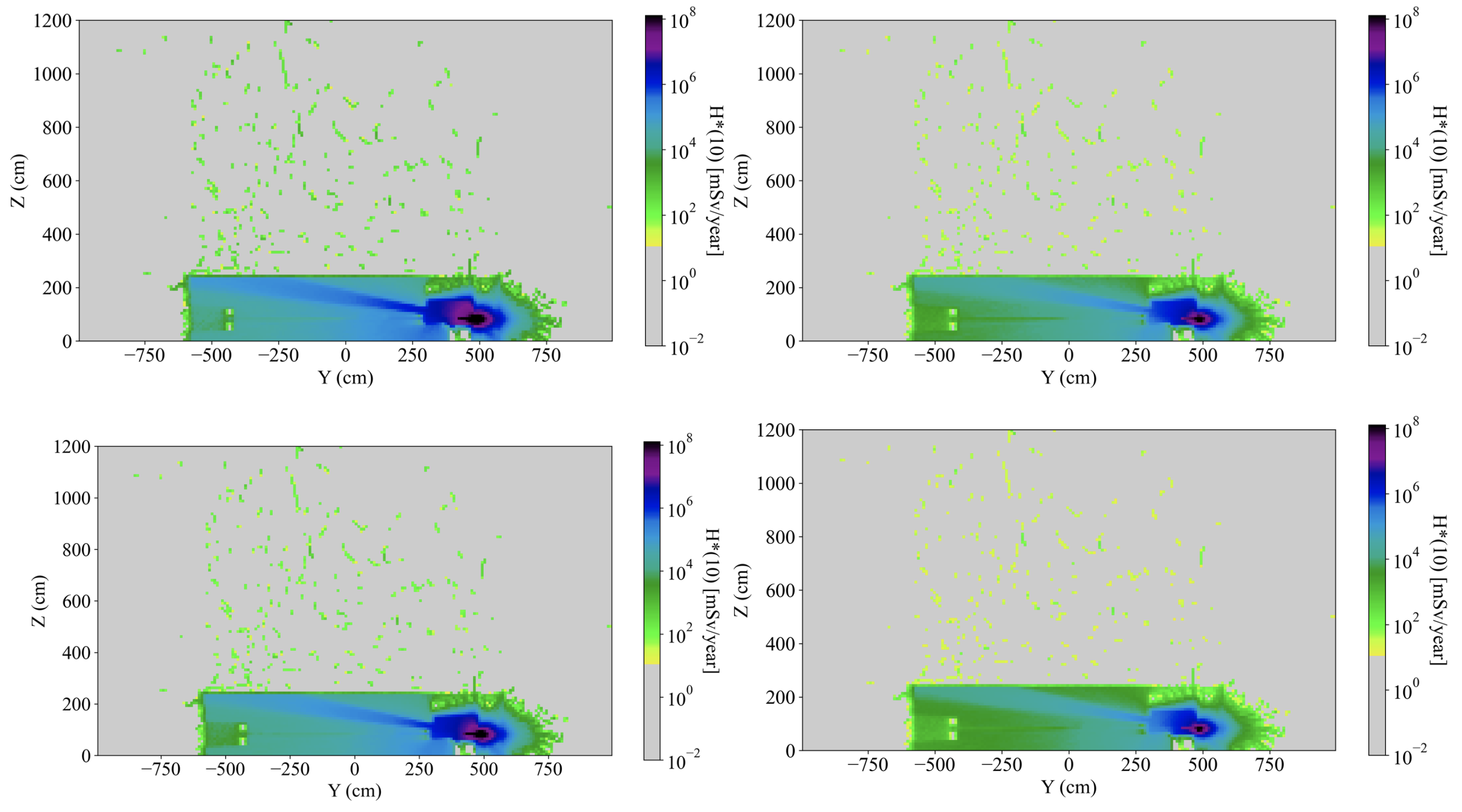
Ambient dose equivalent maps presented in Figure 9 illustrate the distribution of gamma and neutron radiation before the implementation of shielding. The dose map in the top-right of Figure 9 highlights significant skyshine effects from photon radiation (X-ray and gamma radiation), where radiation scatters upward and reaches the accelerator hall roof, posing a potential safety concern. In contrast, skyshine radiation from neutrons shows a significantly lower dose than that from photons, as depicted in the bottom-right dose map of this figure. The unshielded scenario underscores the importance of implementing effective radiation shielding to protect personnel and the surrounding environment, particularly in mitigating skyshine effects from photons. Post-shielding dose equivalent maps, shown in Figure 10, reveal a substantial reduction in radiation levels due to the multilayer shielding design. The shielding was specifically configured to mitigate both direct and scattered radiation. Despite the improvements, a minor amount of radiation leakage to the roof was observed, which underscores the need for continuous optimization of the shielding design to meet safety standards. The addition of a radiation absorber to the front wall downstream of the experimental setup is planned to reduce excessive radiation leakage. This optimization will be implemented during the design phase of the electron beam irradiation setup and will be presented in a separate publication. The electron parameters used in this simulation include a beam energy of 25 MeV, bunch charges of 60 and 10 pC, and a macropulse duration of 6 s.
To evaluate the shielding’s adaptability and efficiency under varying operating conditions, additional simulations were performed with different electron parameters, including beam energy, bunch charge, and pulse duration. For example, Figure 11 shows dose equivalent maps for a reduced beam energy of 10 MeV and a lower bunch charge of 30 pC, both of which resulted in significantly lower radiation levels. This indicates that reducing the electron beam’s energy and charge contributes to better radiation containment. Additionally, the impact of varying macropulse durations on shielding performance was investigated. Simulations were conducted for macropulse durations of 1 s and 6 s, and the results, also presented in Figure 11, demonstrate that shorter macropulse durations lead to more effective radiation shielding. This outcome is attributed to the reduced overall energy and particle flux associated with shorter pulses, which minimizes radiation leakage and scattering.
The findings of this investigation emphasize the critical importance of carefully designing the shielding structure and selecting appropriate materials for the case of electron beam irradiation. Additionally, optimizing electron beam parameters, particularly the beam energy, macropulse duration and bunch charge, before conducting electron beam irradiation experiments on samples at this station is crucial. Proper parameter selection not only enhances shielding effectiveness but also ensures compliance with safety regulations and minimizes potential risks to personnel and infrastructure. These insights are essential for guiding the design and operation of the irradiation station setup.
3.3. Analysis of B-Factor
The behavior of gamma-ray attenuation through materials and the determination of the B-factor were analyzed using a fitting function. This analysis starts by summing gamma-ray simulations across various material thicknesses. The mass attenuation coefficient values, obtained from the National Institute of Standards and Technology (NIST), were employed to calculate the attenuation coefficient (). The B-factor is then parameterized as a function of thickness (x) using a combination of a quadratic term and an exponential correction, as shown in Equation (4):
To simplify the fitting process, the natural logarithm of the radiation intensity equation was applied, resulting in the linearized form presented in Equation (5):
This nonlinear fitting approach was used to optimize the B-factor and refine the logarithmic attenuation model. The fitting parameters a, b, c, and d in Equation (4) were adjusted to align the model with observed intensity values, providing an accurate characterization of the B-factor and material attenuation behavior.
Figure 12a illustrates the relationship between the B-factor and the thickness of lead shielding for gamma-ray energies ranging from 0.3 to 5 MeV. The B-factor increases with shielding thickness, reflecting the buildup of scattered radiation. For low-energy gamma-rays (e.g., 0.3 MeV), the B-factor rises sharply at smaller shielding thicknesses of lead before plateauing, indicating effective attenuation. In contrast, high-energy gamma-rays (e.g., 5 MeV) exhibit a more gradual increase, necessitating thicker shielding to mitigate scattered radiation effectively. The B-factor trends for iron shielding are depicted in Figure 12b. Similar to lead, the B-factor increases with thickness due to radiation buildup within the material, but the rate of increase and the trends vary with the gamma-ray energy. Compared to lead with higher atomic number, iron exhibits a more pronounced buildup effect at equivalent thicknesses, leading to higher B-factors for high-energy gamma-rays. This implies that thicker iron shielding is required to achieve comparable attenuation and suppression of radiation buildup. Concrete, with a lower atomic number than lead and iron, demonstrates an even greater buildup effect for equivalent thicknesses, particularly for high-energy gamma-rays (Figure 12c). Consequently, significantly thicker concrete shielding is required to achieve similar attenuation and suppress scattered radiation effectively.
The results of this study were compared with those from other research. Kiyani et al. (2013) [15] employed the Monte Carlo code MCNP4C to simulate gamma-ray shielding with a variety of materials, including depleted uranium, uranium dioxide, natural uranium, tin, water, and concrete. Their findings align closely with the results of our work, particularly in showing that the B-factor increases with shielding thickness. A detailed comparison of B-factors for concrete at gamma-ray energies of 0.5 MeV, 1 MeV, 2 MeV, and 4 MeV revealed good overall agreement. Slight deviations were observed at higher gamma-ray energies and greater concrete thicknesses, which can be attributed to differences in modeling assumptions and methodologies. Specifically, the slightly higher B-factors obtained in our study likely reflect a conservative estimation of the contribution of scattered radiation.
From a radiation protection perspective, a higher B-factor implies a more cautious estimation of scattered radiation, which ensures adequate shielding under a wide range of radiation conditions. While this approach may lead to overestimation of dose levels, it offers an additional margin of safety, which is critical in scenarios with significant uncertainty or variability in radiation exposure. However, it is essential to balance safety with practical considerations. Excessively high B-factor values could result in overly stringent shielding requirements, leading to increased costs and unnecessary material usage. Optimizing the B-factor to accurately reflect scattered radiation contributions without being excessively conservative is, therefore, crucial for achieving cost-effective and efficient shielding solutions. This comparison underscores the importance of reconciling theoretical predictions with experimental and simulated data to refine B-factor estimations. Future studies could focus on comparison of simulation results with future measurement data to verify the accuracy and applicability of shielding models.
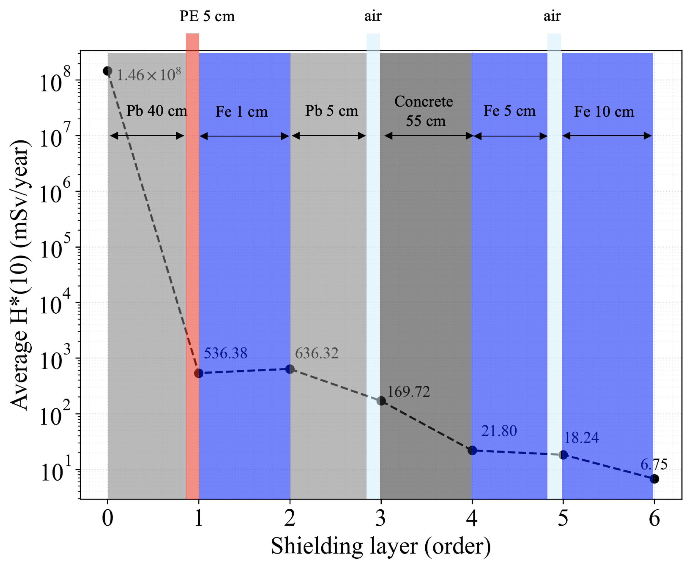
To analyze the attenuation of gamma radiation through layered shielding materials, a theoretical model incorporating the B-factor and attenuation coefficients was developed and applied. The radiation intensity was calculated iteratively for each material layer using Equation (3). The sequential calculation was performed across layers of lead, iron, and concrete, each characterized by known thicknesses and attenuation coefficients as specified in Section 3.1. The B-factor was utilized to account for the contribution of scattered radiation within the shielding materials. The results demonstrated a significant reduction in intensity as the gamma-rays traversed successive layers, highlighting the combined effects of attenuation and radiation buildup. The application of the B-factor provided a more realistic representation of scattered radiation, which is often overlooked in simpler attenuation models. The relationship between the ambient dose equivalent and the shielding layers, presented on a logarithmic scale in Figure 13, illustrates the effectiveness of the multi-layered shielding configuration.
The final value of the calculated attenuation through multilayer shielding using the B-factor at z = 280 cm is 6.75 mSv/y, which is higher than the dose value of 0.54 mSv/y obtained from the GEANT4 Monte Carlo simulation, as presented in Figure 9 and discussed in Section 3.1. This discrepancy may stem from the position of the scorer within the beam dump, which has a thickness of 10 cm, as depicted in the inset of Figure 4. The scorer at z = 20 cm collects more gamma radiation compared to the one at z = 280 cm. This is because the shape and configuration of the beam dump and shielding layers cause gamma radiation to scatter and propagate in multiple directions, rather than following a straightforward upward trajectory. This analysis underscores the importance of accurately accounting for scattered radiation when designing and evaluating shielding systems. While the B-factor improves the fidelity of predictions by incorporating scattered radiation effects, discrepancies such as those observed in this study highlight the influence of geometric and positional factors on dose measurements. Therefore, the buildup factor was used to optimize shielding structures and determine the proper material types and their optimal thicknesses for local shielding. However, for accurate ambient dose distribution estimations, GEANT4 Monte Carlo simulations are more appropriate.
4. Conclusions
This study presented the design and optimization of a radiation shielding system for the electron beam irradiation station at the PBP-CMU Electron Linac Laboratory (PCELL), specifically aimed at supporting FLASH radiotherapy applications. Utilizing the GEANT4 Monte Carlo simulation toolkit, multilayer shielding configurations were designed, incorporating materials including lead, iron, polyethylene, and concrete to achieve maximal radiation attenuation. Key results demonstrate that the optimized shielding successfully reduced the ambient dose equivalent in public areas outside the accelerator hall to below the regulatory limit of 1 mSv/year, ensuring compliance with international safety standards. For controlled areas, the shielding maintained exposure levels within the permissible limit of 20 mSv/year for radiation workers. The investigation into the B-factor highlighted its critical role in accounting for scattered radiation, providing insights into the attenuation behavior of different materials. The required thickness of the shielding material depends on the energy of photons. For example, lead, due to its high density, effectively attenuates low-energy gamma-rays (e.g., 0.15 MeV) with a sharp dose reduction at small thicknesses. However, high-energy gamma-rays (e.g., 5 MeV) require greater thicknesses to achieve comparable attenuation.
The inclusion of multilayer shielding around the beam dump and irradiation station reduced gamma radiation by several orders of magnitude. Post-shielding dose equivalent maps showed minimal radiation leakage, primarily confined to the accelerator hall roof, which is designated as a restricted area. The ambient dose equivalent for neutron radiation also demonstrated substantial reduction due to the effective use of polyethylene for neutron moderation. Furthermore, simulations of various electron beam parameters reveal the importance of carefully selecting operating conditions to optimize shielding performance and minimize radiation risks. This study not only ensured the safe operation of the electron beam irradiation station but also provided a framework for designing cost-effective and efficient radiation shielding systems. This research not only addresses the unique safety challenges posed by the PCELL facility but also contributes to the broader field of radiation protection. Future work will involve the construction of shielding system and experimental validation of the the shielding performance as well as further refinement to enhance safety and operational flexibility. The methodologies and findings presented offer a useful framework for designing efficient and cost-effective shielding systems, with potential applications extending to other electron beam facilities.
Author Contributions
Conceptualization: K.K. and S.R.; methodology: K.K., S.R., P.J. and P.A.; validation: S.R.; formal analysis: K.K.; investigation: K.K.; resources: S.R.; data curation: K.K.; writing—original draft preparation: K.K.; writing—review and editing: S.R.; visualization: S.R.; supervision: S.R.; project administration: S.R.; funding acquisition: S.R. All authors have read and agreed to the published version of the manuscript.
Funding
This research project was supported by the Fundamental Fund 2024, Chiang Mai University (Grant No. FF094/2567).
Data Availability Statement
The data that support the findings of this study are available from the corresponding author (S.R.) upon reasonable request.
Acknowledgments
This research project was supported by the Fundamental Fund 2024, Chiang Mai University (Grant No. FF094/2567). The authors also acknowledge the significant contributions of Watchara Jaikla and Supasin Sukara in creating the 3D drawings of the accelerator system, building structure, and radiation shielding. We extend our sincere thanks to Chitrlada Tongbai and Jatuporn Saisut for their valuable suggestions. K. Kongmali gratefully acknowledges the scholarship support from the Science Achievement Scholarship of Thailand (SAST).
Conflicts of Interest
The authors declare no conflicts of interest.
References
Hughes, J.R.; Parsons, J.L. FLASH radiotherapy: Current knowledge and future insights using proton-beam therapy. Int. J. Mol. Sci.2020, 21, 6492. [Google Scholar] [CrossRef] [PubMed]
Lin, B.; Gao, F.; Yang, Y.; Wu, D.; Zhang, Y.; Feng, G.; Dai, T.; Du, X. FLASH radiotherapy: History and future. Front. Oncol.2021, 11, 644400. [Google Scholar] [CrossRef] [PubMed]
Rimjaem, S.; Kusoljariyakul, K.; Thongbai, C. RF study and 3-D simulations of a side-coupling thermionic RF-gun. Nucl. Instrum. Methods Phys. Res. Sect. A Accel. Spectrom. Detect. Assoc. Equip.2014, 736, 10–21. [Google Scholar] [CrossRef]
Saisut, J.; Kusoljariyakul, K.; Rimjaem, S.; Kangrang, N.; Thongbai, C.; Wichaisirimongkol, P.; Thamboon, P.; Rhodes, M.W.; Thongbai, C. Construction and performance of the magnetic bunch compressor for the THz facility at Chiang Mai University. Nucl. Instrum. Methods Phys. Res. Sect. A Accel. Spectrom. Detect. Assoc. Equip.2011, 637, S99–S106. [Google Scholar] [CrossRef]
Shultis, J.K.; Faw, R.E. Radiation Shielding and Radiological Protection. In Handbook of Nuclear Engineering; Springer: Boston, MA, USA, 2010; pp. 154–196. [Google Scholar]
Rosenstrom, A.; Santana-Leitner, M.; Rokni, S.H.; Shumail, M.; Tantawi, S.; Dewji, S.; Loo, B.W., Jr. Monte Carlo simulation of shielding designs for a cabinet form factor preclinical MV-energy photon FLASH radiotherapy system. Med. Phys.2023, 50, 3055–3065. [Google Scholar] [CrossRef] [PubMed]
Pozzi, F. CERN Radiation Protection (RP) Calibration Facilities. Ph.D. Thesis, Technical University of Munich, Munich, Germany, 2016. [Google Scholar]
Kroese, D.P.; Brereton, T.; Taimre, T.; Botev, Z.I. Why the Monte Carlo method is so important today. Wiley Interdiscip. Rev. Comput. Stat.2014, 6, 386–392. [Google Scholar] [CrossRef]
Ivantchenko, A.V.; Ivanchenko, V.N.; Molina, J.-M.Q.; Incerti, S.L. Geant4 hadronic physics for space radiation environment. Int. J. Radiat. Biol.2012, 88, 171–175. [Google Scholar] [CrossRef] [PubMed]
Jaikaew, P. Design of Radiation Shielding for the PBP-CMU Electron Linac Laboratory. Master of Science Thesis, Chiang Mai University, Chiang Mai, Thailand, 2022. [Google Scholar]
Sazali, M.A.; Rashid, N.K.A.M.; Hamzah, K. A review on multilayer radiation shielding. IOP Conf. Ser. Mater. Sci. Eng.2019, 555, 012008. [Google Scholar] [CrossRef]
Kiyani, A.; Karami, A.A.; Bahiraee, M.; Moghadamian, H. Calculation of gamma buildup factors for point sources. Adv. Mater. Res.2013, 2, 93–98. [Google Scholar] [CrossRef]
Figure 1.
Three-dimensional (3D) drawing of the accelerator system at PCELL, illustrating the electron beam irradiation station located at the left end of the system.
Figure 1.
Three-dimensional (3D) drawing of the accelerator system at PCELL, illustrating the electron beam irradiation station located at the left end of the system.
Figure 2.
The radiation area classification for the PBP-CMU Electron Linac Laboratory (PCELL) consists of three zones: the red area, which represents the controlled area with a radiation dose limit of 20 mSv/y; the yellow area, which represents the supervised area with a radiation dose limit of 6 mSv/y; and the green area, which represents the public area with a radiation dose limit of 1 mSv/y.
Figure 3.
Top view (a) and side view (b) schematic layouts of the accelerator hall and its surrounding area.
Figure 3.
Top view (a) and side view (b) schematic layouts of the accelerator hall and its surrounding area.
Figure 4.
Histogram of gamma radiation distribution as a function of energy range (MeV). The inset illustrates the GEANT4 simulation geometry of the electron beam dump and the scorer.
Figure 4.
Histogram of gamma radiation distribution as a function of energy range (MeV). The inset illustrates the GEANT4 simulation geometry of the electron beam dump and the scorer.
Figure 5.
The relationship between the number of particles and the thickness of shielding materials for various gamma-ray energies.
Figure 5.
The relationship between the number of particles and the thickness of shielding materials for various gamma-ray energies.
Figure 6.
(a) GEANT4 simulation of the 25 MeV electron beam inside the beam dump. (b) Side view of three-dimensional geometry of the beam dump depicting multilayer shielding structure.
Figure 6.
(a) GEANT4 simulation of the 25 MeV electron beam inside the beam dump. (b) Side view of three-dimensional geometry of the beam dump depicting multilayer shielding structure.
Figure 7.
Ambient dose equivalent maps inside the accelerator hall for the case with beam dump shielding. The first column displays top views at a height of 120 cm, while the second column shows side views. The first row represents gamma radiation, while the second row depicts neutron radiation.
Figure 7.
Ambient dose equivalent maps inside the accelerator hall for the case with beam dump shielding. The first column displays top views at a height of 120 cm, while the second column shows side views. The first row represents gamma radiation, while the second row depicts neutron radiation.
Figure 8.
(a) GEANT4 simulation of a 25 MeV electron beam traveling through a 50 m titanium window. (b) Three-dimensional design of the local shielding for the electron beam irradiation station, with concrete shown in dark gray and iron in blue.
Figure 8.
(a) GEANT4 simulation of a 25 MeV electron beam traveling through a 50 m titanium window. (b) Three-dimensional design of the local shielding for the electron beam irradiation station, with concrete shown in dark gray and iron in blue.
Figure 9.
Ambient dose equivalent maps inside the accelerator hall for the case of a 25 MeV electron beam without shielding covering the irradiation station. The first column displays top views at a height of 120 cm, while the second column shows side views. The first row represents gamma radiation, while the second row depicts neutron radiation.
Figure 10.
Ambient dose equivalent maps (side views) inside the accelerator hall for the case of 25 MeV electron beam with shielding covering the irradiation station. The first row represents gamma radiation, while the second row depicts neutron radiation. The first column represents an electron bunch charge of 60 pC, while the second represents 10 pC, both with a 6 s macropulse duration.
Figure 11.
Ambient dose equivalent maps (side views) inside the accelerator hall for a 10 MeV electron beam with shielding covering the irradiation station. The first and second rows, respectively, correspond to macropulse durations of 6 and 1 s, while the first and second columns represent electron bunch charges of 60 and 30 pC, respectively.
Figure 12.
The relationship between the B-factor and the thickness of shielding materials (in cm) at various gamma-ray energies.
Figure 12.
The relationship between the B-factor and the thickness of shielding materials (in cm) at various gamma-ray energies.
Figure 13.
The relationship between the ambient dose equivalent and the order of shielding layers with materials’ optimized thicknesses. The gray, pink, light purple, light blue, and dark gray colors represent layers of lead, polyethylene, iron, air, and concrete, respectively.
Figure 13.
The relationship between the ambient dose equivalent and the order of shielding layers with materials’ optimized thicknesses. The gray, pink, light purple, light blue, and dark gray colors represent layers of lead, polyethylene, iron, air, and concrete, respectively.
Disclaimer/Publisher’s Note: The statements, opinions and data contained in all publications are solely those of the individual author(s) and contributor(s) and not of MDPI and/or the editor(s). MDPI and/or the editor(s) disclaim responsibility for any injury to people or property resulting from any ideas, methods, instructions or products referred to in the content.
Kongmali, K.; Apiwattanakul, P.; Jaikeaw, P.; Rimjaem, S.
Localized Multilayer Shielding of an Electron Beam Irradiation Station for FLASH Radiotherapy Experiments. Particles2025, 8, 51.
https://doi.org/10.3390/particles8020051
AMA Style
Kongmali K, Apiwattanakul P, Jaikeaw P, Rimjaem S.
Localized Multilayer Shielding of an Electron Beam Irradiation Station for FLASH Radiotherapy Experiments. Particles. 2025; 8(2):51.
https://doi.org/10.3390/particles8020051
Chicago/Turabian Style
Kongmali, Kanlayaporn, Pittaya Apiwattanakul, Phanthip Jaikeaw, and Sakhorn Rimjaem.
2025. "Localized Multilayer Shielding of an Electron Beam Irradiation Station for FLASH Radiotherapy Experiments" Particles 8, no. 2: 51.
https://doi.org/10.3390/particles8020051
APA Style
Kongmali, K., Apiwattanakul, P., Jaikeaw, P., & Rimjaem, S.
(2025). Localized Multilayer Shielding of an Electron Beam Irradiation Station for FLASH Radiotherapy Experiments. Particles, 8(2), 51.
https://doi.org/10.3390/particles8020051
Article Metrics
No
No
Article Access Statistics
For more information on the journal statistics, click here.
Multiple requests from the same IP address are counted as one view.
Kongmali, K.; Apiwattanakul, P.; Jaikeaw, P.; Rimjaem, S.
Localized Multilayer Shielding of an Electron Beam Irradiation Station for FLASH Radiotherapy Experiments. Particles2025, 8, 51.
https://doi.org/10.3390/particles8020051
AMA Style
Kongmali K, Apiwattanakul P, Jaikeaw P, Rimjaem S.
Localized Multilayer Shielding of an Electron Beam Irradiation Station for FLASH Radiotherapy Experiments. Particles. 2025; 8(2):51.
https://doi.org/10.3390/particles8020051
Chicago/Turabian Style
Kongmali, Kanlayaporn, Pittaya Apiwattanakul, Phanthip Jaikeaw, and Sakhorn Rimjaem.
2025. "Localized Multilayer Shielding of an Electron Beam Irradiation Station for FLASH Radiotherapy Experiments" Particles 8, no. 2: 51.
https://doi.org/10.3390/particles8020051
APA Style
Kongmali, K., Apiwattanakul, P., Jaikeaw, P., & Rimjaem, S.
(2025). Localized Multilayer Shielding of an Electron Beam Irradiation Station for FLASH Radiotherapy Experiments. Particles, 8(2), 51.
https://doi.org/10.3390/particles8020051


