Abstract
An intense narrow-band terahertz (THz) radiation source has been designed to generate a broad tuning range of radiation frequencies between 0.5 THz and 5.0 THz. The THz radiation is produced when a short-bunch electron beam propagates through an undulator. To achieve high-power peak radiation, the source requires high-brightness electron beams with low beam emittance and short bunch length. A proposed design for the photocathode RF gun used as the electron source is presented. The gun with high mode separation and high Q-factor can be achieved for producing a good beam quality. The beam dynamics of the injector have been preliminarily optimized using the software ASTRA and Elegant, investigating the impact of laser pulse shape on electron beam quality. The results of the beam dynamics studies are comprehensively discussed in this paper.
1. Motivation
To support the increasing demand for agriculture, food, and materials industries in Thailand, SLRI is developing a THz radiation source capable of generating intense THz radiation, as proposed in [1]. Figure 1 shows the layout design of the THz source, which has the potential to generate intense, narrow-band, and tunable THz coherent radiation in the frequency range of 0.5 to 5.0 THz. Achieving higher power in generating THz radiation relies on the essential optimization of the electron beam. For the coherent condition of radiation, it is necessary that the bunch length of electrons is either comparable or shorter than the wavelength of the radiation. Therefore, a photocathode RF gun will be used as the electron source, and the emitted electron beam will be accelerated to 30 MeV energy by a high-gradient linac [2]. To generate the intense THz coherent radiation, the goal of electron bunch length must be compressed to 100 fs by a chicane bunch compressor before passing through an undulator [1]. The primary objective of this study is to focus on the design and beam dynamic analyses of an injector for a compact THz coherent radiation source, enabling a broad range of radiation frequency.
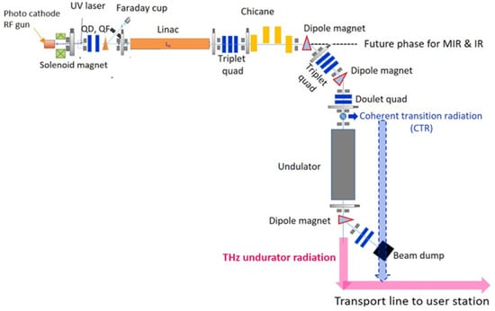
Figure 1.
Layout of THz radiation source [1].
This paper consists of four main sections. The general information of photocathode RF gun is described in Section 2. Section 3 presents the electromagnetic field simulation and the design of the photocathode RF gun, which includes details of the gun geometry and its performance. Section 4 describes how the optimization of beam dynamics was conducted by varying the shape of the laser pulse used to illuminate the photocathode. The impact of laser pulse shape on electron beam properties is discussed, and the resulting electron beam brightness is analyzed. It provides insights on how laser pulse optimization can minimize transverse emittance and improve electron beam properties. Finally, Section 5 presents the conclusion of the study.
2. Photocathode RF Gun
Advanced technology has enabled the development of highly efficient electron sources, such as photocathode sources, also known as electron guns. Photocathode RF-gun are widely utilized in various fields that demand a high-intensity electron beam and have several advantages, including the ability to generate beams with high charge and low emittance, making them useful in various applications such as particle accelerators and free-electron lasers. In the photocathode RF-gun, electrons are generated according to the photoelectric effect. The process begins with a laser pulse being directed onto a photocathode to emit electrons. These electrons are then accelerated using an RF field in a series of cells to produce a high-quality electron beam. When the photon illuminates a metal surface of the cathode material, the electrons can be emitted because the photon energy is transferred to electrons inside the surface of material. Thus, the photon excites the electrons bound in a metal surface to higher energy states [3,4]. The amount of charge in the emitted electron bunch is determined by various factors including the properties of the laser, such as its energy and wavelength, as well as the quantum efficiency of the cathode material. Figure 2 shows the schematic of 1.6 cell s-band photocathode RF gun [3].
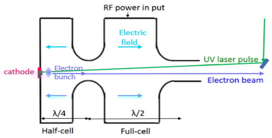
Figure 2.
1.6 cell s-band photocathode RF gun.
Regarding the quality of the electron beam in photocathode RF gun, the emittance can increase rapidly due to the high space-charge effect, causing the beam to diverge quickly after electron emission and entering the first cell. A solenoid magnet is employed for focusing the electron beam. The laser pulse distribution plays a significant role in determining and controlling the electron beam quality. If the electrons are extracted from the cathode with high charge density, the resulting space-charge field can disturb the emittance of the electron beam. Therefore, the laser pulse shape needs to be optimized to ensure high electron beam quality. In addition, the solenoid magnet needs to be optimized to minimize the transverse emittance of the electron beam generated from the photocathode.
3. Electromagnetic Field Simulations of Photocathode RF Gun
The injector system is critical in ensuring high-quality electron beams, and reducing the space charge effect is essential for improving emission from the photocathode RF gun. The significant advantage of using photocathodes is the ability to manipulate the electron bunch distribution through laser pulse manipulation. The electron beam’s shape, produced from the cathode, can be adjusted by changing the laser pulse characteristics. The 1.6-cell photocathode RF gun is a suitable option for generating a large number of high-brightness electrons in a short bunch. To emit electrons, laser pulses with wavelengths ranging from 200–300 nm can be used to illuminate the cathode placed inside the gun. The photocathode RF gun comprises a half-cell cathode and a full-length cell. After illuminating the cathode with laser pulses, the electrons are emitted and then rapidly accelerated using high-gradient fields operating at 2856 MHz.
In the design of the electron gun, the size and structural design of each cell are extremely important. The efficiency of the electron gun depends on its geometry. Our design was based on an electron gun model developed by four research institutes: KEK [5], Tsinghua University [6], PAL FEL [7], and SPARC_Lab [8]. Each model has differences in the length, size, and curvature of half-cells and full-cells, as illustrated in Figure 3. In order to achieve a high-quality gun, the shape has to be optimized with using 2D SUPERFISH simulation [9]. The mode separation and Quality factor (Q-factor) were investigated. The gun design features a higher mode separation that minimizes the excitation of zero mode fields. This design helps to achieve better performance by reducing unwanted effects caused by the zero mode fields [10]. With high Q-factor, the mode frequency remains stable by minimizing temperature variations.
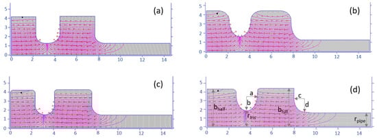
Figure 3.
Electric field simulated by SUPERFISH program (a) Model 1, (b) Model 2, (c) Model 3, and (d) Model 4 photocathode RF gun.
For the RF gun parameters, the peak accelerating field (E0) of 120 MV/m was defined in ASTRA simulation. This field leads to the acceleration of the electron beam to the energy of 5.7 MeV. Electric field distribution inside electron gun based on Model 4 is presented in Figure 4 (left). The surface field values inside the guns Model 2 and Model 4 were lower compared to the Model 1 and Model 3 designs. The electric field at the edge of the electron gun wall can lead to gas discharge, causing damage to the electron gun and instability in the production of electrons. By creating a curved edge for the electron gun wall, either round or oval in shape, it is possible to achieve a low surface field as illustrated in Figure 4 (right). Low surface field results in increased efficiency of the electron gun, as well as enhanced stability in the production of electron beams by minimizing sparking inside the electron gun. It can greatly enhance the performance and stability of the machine during operation.
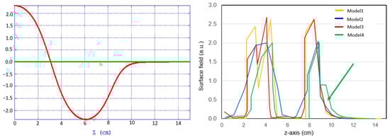
Figure 4.
Electric field from Model 4 gun (left) and surface field (right).
The photocathode RF gun Model 4, shown in Figure 3, has undergone modifications to improve its performance. The iris radius was increased to 25 mm with small steps, and the elliptical shape (with adjusted factors b and a) was adopted to reduce the surface peak electric field on the iris relative to the cathode field. Additionally, the rounded edge of the cell was adjusted to achieve a higher Q-factor value. As a result of these modifications, the gun Model 4 demonstrated better mode separation and quality factor than other gun shapes, as summarized in Table 1. Since the achievement of mode separation of 44 MHz has addressed, the concern issue on mistuning will be mitigated. The high-quality factor and mode separation of the Model 4 gun suggests that the electron beam produced by the gun is highly stable, making it suitable for generating high-brightness electron sources. With using Model 4 design, the electron beam would be obtained with low initial emittance and a linear longitudinal phase space.

Table 1.
Photocathode RF gun parameters.
The next step involves studying the 3D simulation of the electric field, engineering design, thermal analysis, and vacuum performance to ensure a successful design of the RF gun structure. It will be presented in the next paper.
4. Beam Dynamics Studies of Injector
The electric field generated from the Model 4 photocathode RF gun in Section 3 was used in simulations. The electric field of the RF gun remains unchanged at 120 MV/m. This beam was accelerated to over 10 MeV by utilizing a linac with an RF frequency of 2856 MHz, located downstream of the solenoid. According to [2], the beam exit energy from the linac was 30 MeV, which was achieved by applying an accelerating field gradient of 11 MV/m.
The beam dynamics optimization was performed by using software ASTRA [11], which incorporates 3D space-charge forces in simulations. A bunch charge of 1.0 nC/bunch was assumed to be generated from the RF gun. Techniques, such as optimizing the laser pulse shape, can be employed to address concerns related to space charge effects, as described in reference [12,13,14]. Although solenoid focusing can compensate for the linear space-charge force, it may not be sufficient to address the nonlinear space-charge force on the cathode surface. Therefore, optimizing the laser pulse shape can be an effective way to mitigate space charge effects.
This study aimed to minimize the normalized transverse emittance downstream of the linac by varying the shape of the laser pulse used to illuminate the photocathode. Three different shapes of the photocathode laser pulse were used to investigate their impact on electron beam properties. The laser pulse distributions are listed in Table 2. It examines how different shapes of the photocathode laser pulse affected the initial properties of the electron beam and how this influenced the resulting electron beam brightness after it was compressed using a Chicane magnet. The findings can inform the optimization of the laser pulse shape to improve electron beam properties and brightness.
Table 2.
Laser pulse distribution used in simulation.
The solenoid field was applied to compensate for the transverse emittance, as it is used for beam focusing and transverse emittance conservation. The space-charge field produced by electrons emitted from the cathode can cause defocusing forces and lead to transverse beam expansion at the beginning of acceleration. This study investigates the effect of solenoid magnets on the transverse beam emittance downstream of the gun. The solenoid magnet is placed 0.189 m downstream of the RF gun. A magnetic field generated by solenoid magnet is shown in Figure 5 (left). It refers to the field distribution in longitudinal direction. The transverse beam emittance can be optimized by using the solenoid field. Figure 5 (right) presents the transverse beam emittance at various solenoid magnetic field strength. To investigate the proper solenoid magnetic field with a charge of 1 nC, the injection phase was varied from −16 to 0 degrees and changed the solenoid field from 0.26 to 0.28 Tesla. The parameters of laser pulse were kept unchanged with using a laser pulse of 8 ps and spot size of 0.5 mm. It was found that the optimal solenoid magnetic field is 0.278 Tesla with a fixed RF phase of −6 deg.
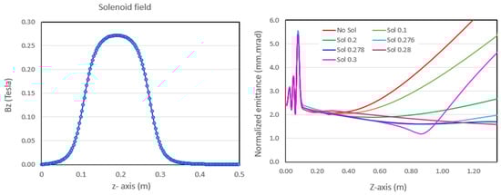
Figure 5.
Magnetic field of the solenoid (left) and emittance along z-axis for a 1 nC bunch charge (right) (8 ps laser pulse and 0.5 mm laser spot size).
Figure 6 plots the dependences of the transverse emittance on the size of the laser pulse and longitudinal laser pulse. The emittance was investigated from photocathode RF gun to the linac exit. It was found that the laser spot size must be optimized not only for emittance compensation but also to match the beam properties before going to the linac, which is positioned at 1.35 m from the cathode. The length of the laser pulse is 8 ps (rms), and the size of the laser pulse is approximately equal to the size of the electron beam emitted from the cathode. Assuming a drive laser with a plateau distribution in both longitudinal and transverse axes (with a pulse duration of 8 ps and rms beam size of 0.5 mm at the cathode surface), we achieved a minimum emittance value of 1.20 mm-mrad for the optimal solenoid field of 0.278 Tesla and RF phase of −8 degree. This corresponds to better matching of the beam envelope in the linac.
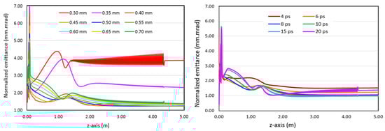
Figure 6.
Transverse normalized emittance along z-axis versus (left) laser spot size and (right) longitudinal pulse distribution for 1 nC bunch charge with 0.5 mm laser spot size.
Figure 7 shows the emittance from RF gun to the linac exit for a 1 nC bunch charge and different pulse shapes. The optimized beam emittance is dependent on laser pulse distribution. Laser pulse shape was varied to minimize the normalized transverse emittance at the location of the linac downstream, delivering a beam energy of ~30 MeV. The solenoid field of 0.278 Tesla can be able to decrease the emittance to 0.6 mm-mrad for using ellipse laser shape. It is worth pointing out that the use of ellipsoidal distribution is a good shape to achieve the minimize emittance. One of the advantages of applying the ellipsoidal laser profile is expressed in less nonlinearity and more regular shape of the longitudinal phase space. Figure 8 presents a comparison of the longitudinal phase space of the electron beam for different laser profiles. That means the space charge effect gets lower. It allows us to understand how to reduce the space charge effect for the high charge electron beam in the photocathode RF gun.
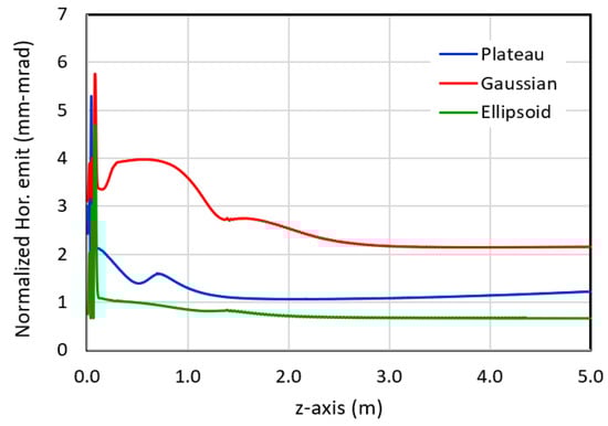
Figure 7.
Transverse emittance at the bunch charge of 1 nC with using a pulse duration of 8 ps and spot size of 0.5 mm.
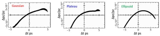
Figure 8.
Longitudinal phase spaces at the linac exit.
However, although an ellipsoidal distribution can result in a minimum emittance, obtaining such a shape can be complicated using techniques such as SLIM [15]. In this system, a plateau shape is considered more suitable. Therefore, the electron beam with emittance of 1.2 mm-mrad at the end of linac and beam size less than 0.1 mm was obtained.
Regarding the coherent undulation radiation, it can be emitted from electrons passing through a periodic field undulator under the condition that the electron bunch length must be equal or shorter than the radiation wavelength. A chicane bunch compressor is a device used in particle accelerators to compress electron bunches. It consists of a series of dipole magnets that obtain a short bunch length by rotating the longitudinal phase space [16].
To simulate a bunch compressor, the electron bunch was modeled using Elegant [17]. As the chirped electron bunch passes through a chicane bunch compressor, the dipole magnets within the chicane cause electrons with varying energies to travel different distances, leading to a partial reversal of the energy chirp, which refers to the variation of electron energy within a bunch. To obtain the minimum bunch length after compression, the longitudinal phase space prior to the chicane magnet must be suitable and match the energy chirp of the initial bunch. Figure 9 shows the bunch length and normalized emittance along z-axis during compression. The electron bunch length and emittance are 0.29 ps and 2.44 mm-mrad, respectively. Although the resulting emittance after compression reaches to 2.44 mm-mrad, it did not significantly impact on the generation of THz radiation. To ensure that the electron beam has suitable optics for entering the undulator, triplet quadrupoles and doublet quadrupoles are placed downstream of the undulator to minimize the electron beam size to less than 1 mm. However, the generation of THz undulator radiation could be affected by the presence of space charge, particularly in scenarios with high bunch charge beam under the condition of high-filed undulator. In the upcoming step, an in-depth investigation will be carried out to determine the influence of the undulator magnetic field on the electron beam.
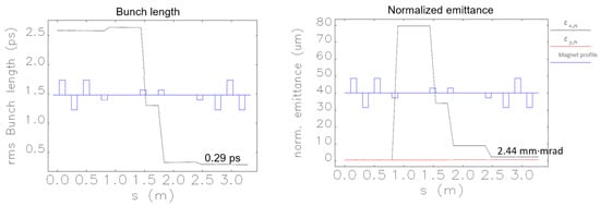
Figure 9.
Electron bunch length (left) and normalized emittance when electron passing through a chicane magnet (right).
5. Conclusions
This paper focuses on designing a photocathode RF gun and optimizing the electron beam dynamics of an injector. To achieve high performance of source, the paper proposes a conceptual design for the gun that features a high mode separation of 44 MHz. By utilizing plateau and ellipsoid laser shapes, the space charge effect is mitigated, and the beam dynamics can be easily optimized to generate a high-quality electron beam. The plateau laser pulse, in particular, produces an emittance of 2.44 mm-mrad and a bunch length of 0.29 ps after compression. The study highlights the importance of optimizing photocathode laser pulse shaping to produce a high-quality electron beam with a short bunch length, which is essential for generating intense THz radiation. This study would be applied for other accelerator sources and also the electron source for a synchrotron light source in the future.
Author Contributions
S.J. conceived the concept and method, performed the design and simulation, and analyzed the results; W.P. conceived the concept and method and corrected the writing; T.C. designed the bunch compressor and did the simulation; N.J. advised the simulation and discussed the results. This research was carried out under the supervision of S.C., S.K. and S.J. wrote the paper. All authors have read and agreed to the published version of the manuscript.
Funding
This research was funded by the Science, Research, and Innovation Fund (SRI fund), Thailand.
Data Availability Statement
Not applicable.
Conflicts of Interest
The authors declare no conflict of interest.
References
- Jummunt, S.; Chanwattana, T.; Chunjarean, S.; Junthong, N.; Klinkhieo, S.; Pulampong, T.; Sunwong, P. Considered design and radiation calculation for a compact THz coherent radiation source. J. Phys. Conf. Ser. 2022, 2431, 012075. [Google Scholar] [CrossRef]
- Siriwan, J.; Somjai, C.; Nawin, J.; Keerati, M.; Supat, K. Design study of 30 MeV linac for a compact THz radiation source. In Proceedings of the 13th International Particle Accelerator Conference, Bangkok, Thailand, 12–17 June 2022; pp. 2643–2644. [Google Scholar]
- David, T.R.; Dowell, H. An Engineering Guide to Photoinjectors. Available online: http://arxiv.org/abs/1403.7539 (accessed on 19 April 2023).
- Fraser, J.S.; Sheffield, R.L.; Gray, E.R.; Rodenz, G.W. High-Brightness Photoemitter Injector for Electron Accelerators. IEEE Trans. Nucl. Sci. 1985, 32, 1791–1793. [Google Scholar] [CrossRef]
- Terunuma, N.; Murata, A.; Fukuda, M.; Hirano, K.; Kamiya, Y.; Kii, T.; Kuriki, M.; Kuroda, R.; Ohgaki, H.; Sakaue, K.; et al. Improvement of an S-band RF gun with a Cs2Te photocathode for the KEK-ATF. Nucl. Instrum. Methods Phys. Res. 2010, 613, 1–8. [Google Scholar] [CrossRef]
- Qian, H.J.; Du, Y.C.; Yan, L.X.; Li, C.; Hua, J.F.; Huang, W.H.; Tang, C.X. RF design and high power tests of a new Tsinghua photocathode RF gun. In Proceedings of the FEL2012, Nara, Japan, 26–31 August 2012; pp. 165–167. [Google Scholar]
- Hong, J.; Han, J.H.; Park, S.J.; Kang, H.S.; Gil, K. New RF-gun design for the PAL-XFEL. In Proceedings of the FEL2012, Nara, Japan, 26–31 August 2012; pp. 129–131. [Google Scholar]
- David, A.; Antonio, B.; Massimo, F.; Luca, F.; Valerio, L.; Luca, F.; Valerio, P.; Sean, C.; Eylene, P.; Pietro, M.; et al. New technology based on clamping for high gradient radio frequency photogun. Phys. Rev. Accel. 2015, 18, 092001. [Google Scholar]
- Menzel, M.T.; Stokes, H.K. User’s guide for the POISSON/SUPERFISH Group of Codes. Available online: https://www.osti.gov/servlets/purl/10140823 (accessed on 30 November 2022).
- Deshpande, A.; Araki, S.; Fukuda, M.; Sakaue, K.; Terunuma, N.; Urakawa, J.; Sasao, N.; Washio, M. Design of a mode separated RF photo cathode gun. Nucl. Instrum. Methods Phys. Res. 2009, 600, 361–366. [Google Scholar] [CrossRef]
- Flöttmann, K. ASTRA (Versions 1.0 and 1.1), A Space Charge Tracking Algorithm. Available online: https://www.desy.de/~mpyflo (accessed on 30 November 2022).
- Kim, K.J. RF and space-charge effects in laser-driven RF electron guns. Nucl. Instrum. Methods A 1989, 275, 201–218. [Google Scholar] [CrossRef]
- Hyun, K.; Yim, C.M.; Parc, Y.W.; Park, J.H.; Ko, I.S.; Kim, C.; Park, J. Longitudinal laser pulse shaping for low-emittance electron-beam generation. J. Korean Phys. Soc. 2009, 54, 381–385. [Google Scholar] [CrossRef]
- Siriwan, K.; Shuya, C.; Heishun, Z.; Toshiteru, K.; Hideaki, O. Manipulation of laser distribution to mitigate the space-charge effect for improving the performance of a THz coherent undulator radiation source. Particles 2018, 1, 238–252. [Google Scholar]
- Rublack, T.; Khojoyan, M.; Krasilnikov, M.; Stephan, F.; Hartl, I.; Schreiber, S.; Andrianov, A.; Gacheva, E.; Khazanov, E.; Mironov, S.; et al. Development of a quasi 3-D ellipsoidal photo cathode laser system for PITZ. In Proceedings of the IPAC’14, Dresden, Germany, 15–20 June 2014; pp. 2071–2096. [Google Scholar]
- Mitri, S.D. Bunch-length Compressors. CERN Yellow Rep. Sch. Proc. 2018, 1, 363. [Google Scholar]
- Michael, B. Elegant: A Flexible SDDS-Compliant Code for Accelerator Simulation; Advanced Photon Source Light Source Note LS-287; Argonne National Lab.: Lemont, IL, USA, August 2000.


Disclaimer/Publisher’s Note: The statements, opinions and data contained in all publications are solely those of the individual author(s) and contributor(s) and not of MDPI and/or the editor(s). MDPI and/or the editor(s) disclaim responsibility for any injury to people or property resulting from any ideas, methods, instructions or products referred to in the content. |
© 2023 by the authors. Licensee MDPI, Basel, Switzerland. This article is an open access article distributed under the terms and conditions of the Creative Commons Attribution (CC BY) license (https://creativecommons.org/licenses/by/4.0/).