Abstract
This research aims to actively suppress vibrations at the end-effector of a flexible manipulator. When configured in a locked state, the system behaves as a two-link manipulator subjected to disturbances on the first link. To analyze its behavior, Finite Element Analysis (FEA) is employed to extract the natural frequencies (eigenvalues) and corresponding mode shapes (eigenvectors) of a two-link, two-joint flexible manipulator (2L2JM). The obtained eigenvectors are transformed into uncoupled state-space equations using balanced realization and the Match-DC-Gain model reduction algorithm. An H-infinity controller is then designed and applied to both the full-order and reduced-order models of the manipulator. The objective of this study is to validate an analytical framework through FEA, demonstrating its applicability to complex manipulators with multiple joints and flexible links. Given that the full state-space representation typically results in high-dimensional matrices, model reduction enables effective vibration control with a minimal number of states. The derivation of the 2L2JM state space, its model reduction, and a subsequent control strategy have not been previously addressed in this manner. Simulation results showcasing vibration suppression of a cantilever beam are presented and benchmarked against two alternative modeling approaches.
1. Introduction
Improving breeding techniques through phenotyping is one of the most important tasks to prepare enough food resources for the next generation. Crop monitoring is performed using different methods and vehicles, including UAVs (unmanned aerial vehicles) and mobile robots [1]. The motivation of this study relates to developing a vehicle for automated crop monitoring. A 5-DOF (degree of freedom) manipulator has already been developed in-house and is going to be installed on a mobile robot for autonomous travelling on a farm/breeding field. The manipulator produces vibration when the mobile robot, which carries it, traverses a rough farming terrain. To address this problem, vibration needs to be suppressed. In other words, a controller must be designed and implemented so that one or two joints operate to damp the vibration of the end-effector (EE).
Active vibration control of flexible-link manipulators (FLMs) requires a good mathematical model and a controller. However, there are a few control schemes that can be implemented without the need for mathematical modeling. One simple and model-free approach for vibration suppression of FLMs is strain gauge measurement. In this approach, the gravity-liberated strain of the clamped side of the FLM is fed to the controller. Based on this, Phung et al. [2] applied a multi-layer perceptron neural network (NN) for forward and inverse kinematics of a 3-DOF FLM under gravity. For the vibration suppression task, the mean liberated strain is fed to the P-action controller in a cascade controller. In another study on the same FLM, a cascade control scheme for position and vibration suppression is proposed by Malzahn et al. [3]. They implemented two different control approaches based on direct strain feedback (DSFB). One was a half integrator controller for joint positions, and the other was the classic proportional controller for joint velocities. To eliminate the effect of gravity on strain gauge measurement, the mean liberated strain was derived through a finite impulse response filter (FIR filter). In another study, Njery et al. [4] used an NN to tune the gain of DSFB for bending and torsional vibration control of a 3-DOF FLM in the presence of gravity. Also, they used system identification to model a 2-DOF FLM; they attenuated the vibration through a fixed-filter inverse controller and an adaptive notch filter controller. Another model-free approach is Iterative Learning Control (ILC). This is a simple method for the control of repetitive motions such as periodic vibration. ILC performance is improved by learning from experience. Meng et al. [5] implemented a PD-type boundary ILC law for vibration control of a 1-DOF FLM with command torque exerted on the joint. In another publication [6], the same authors implemented ILC with consideration of input saturation of the joint torque. Regarding neural network modeling, Jamali et al. [7] investigated modeling of a 2-DOF FLM. Then, in another publication [8], two PID controllers for each link were designed for vibration and motion control. The vibrations at the end of each link were measured by accelerometers and suppressed by PZT (piezo-electric) actuators. For each PID controller, a P-type iterative learning algorithm was designed for online gain tuning. Although non-model-based control schemes are capable of vibration attenuation, there is a low confidence in controller performance and system stability [9].
Among model-based active control studies, the AMM (assumed mode method) and FEA (Finite Element Analysis) modeling are of interest. Based on the first method, Pereira et al. [10] presented a double-loop control scheme for motion and vibration control of a 1-DOF FLM. The inner loop is a PD controller, while the outer loop is a zero-order controller called integral resonant control. In similar studies, the authors of [11,12,13,14] used different methods such as a classic controller, SMC (sliding mode control), the SDRE (State-Dependent Riccati Equation), and a fuzzy sliding mode controller to attenuate the EE vibration of a 1-DOF FLM. Nestorović et al. [15] obtained a multi-input–multi-output (MIMO) model of a piezoelectric cantilever beam based on the subspace algorithm. They used a linear quadratic regulator (LQR) to control the vibration of the beam’s end. For a wind tunnel cantilever sting (treated as a cantilever beam), Shen et al. [16] fitted a transfer function to a measured frequency response of the first mode of vibration. Then a PID controller was used, and controller gains were tuned using a neural network.
The above studies relate to manipulators with relatively simple geometries. To deal with more complex geometry, it is better to take advantage of FEA; besides, it has been shown to be computationally efficient for model-based real-time control in [17]. In [18], FEA for a 5-DOF manipulator was verified through software and experiment. Based on the Newmark method for solving FEA, Karagülle et al. [19] presented simple residual vibration damping for a 2-DOF FLM. In another study, Dubay et al. [20] presented an active vibration controller using MPC (model predictive control). First, the FEA model of a 1-DOF manipulator was derived; then, a finite-element-based MPC was obtained and solved using the Newmark approach. The manipulator was controlled using the joint’s motor and a linear piezoelectric actuator. In [21], Shao et al. presented an impulse controller to control the forced harmonic excitation of a 1-DOF flexible-link flexible-joint manipulator. Given LQR control, the manipulator took advantage of a pair of piezoelectric actuators. To reduce computational cost, a reduced model was applied by increasing the inertia of the hub. Khot et al. [22] used FEA to obtain the eigenvectors of a cantilever beam. They obtained a reduced state-space model of the beam using principal coordinates. They also used linear optimal control to suppress the beam’s tip vibration. Using FEA and Hamilton’s principle, the authors of [23] obtained a mathematical model of a cantilever beam and implemented a combination of a classic controller and fuzzy logic for vibration control of the beam’s tip. Similarly, Kamel et al. [24] suppressed the vibration of a cantilever beam using FEA and fuzzy–classic controllers. In a recent paper [25], Ebrahimi et al. utilized a so-called L1 adaptive controller for a model obtained using FEA for a cantilever beam, and controlled the beam’s vibration. Hatch [26] studied a state-space model reduction of an FLM. According to this work, balanced realization with the help of Match-DC-Gain model reduction is applicable to MIMO systems.
In this paper, a flexible manipulator is modelled as a two-link, two-joint manipulator (2L2JM); the inputs are the joints’ torque, and output is the manipulator tip’s lateral displacement. To obtain a dynamic model of the cantilever beam (representing the flexible manipulator), FEA is utilized. Using principal coordinates, the uncoupled state-space equations of the system are obtained. To verify the model, eigenvalues (and eigenvectors) from manual FEA are compared with those of FEA-ANSYS 2024 R1 software (FEA-A). To reduce the model, balanced realization is applied to sort the state-space model based on the dominant modes. Then, using the Match-DC-Gain model reduction algorithm [27], the model is reduced so that it only includes the first dominant modes of the manipulator. This algorithm removes states with the smallest Hankel singular values. A H-infinity controller is employed for the full and reduced models of the manipulator to suppress vibration caused by an input impulses. Vibration simulations are executed in Simulink/MATLAB.
The contribution of this research is in the verification of the analytical approach (reduced model) with FEA. In particular, this approach could be generalized to any complex manipulator with joints and a flexible arm. The authors applied this for a 5-DOF manipulator [28]. The state space for a 2L2JM has been derived using FEA. The state space usually leads to large matrices for most geometries; a model reduction is needed to control the vibration with a small number of states. Although the control of vibrations of two-link flexible manipulators has been studied before, 2L2JM state-space derivation, model reduction, and control have not previously been addressed as presented here. Simulation results for vibration suppression of the manipulator are obtained and compared with two other different models.
2. Model of Two-Link, Two-Joint Flexible Manipulator (Manual FEA)
This section is based on [18,29]. The 5-DOF manipulator is restricted so that only two of its joints are not fixed. Thus, a two-link, two-joint flexible manipulator (2L2JM), as shown in Figure 1, is considered here. The joints are assumed to have no rotational stiffness and damping. The first joint is assumed to have a simple support condition. According to Figure 1, (X,Y) are the global coordinates; are the local coordinates fixed to element i of the undeformed link, where , with representing the total number of elements for each link; , which represents number of the link; is the accumulated length; is the length of the link; is the length of the element of the link; are the displacement and the slope of node of the link; and are the displacement and slope of the last node of the link, respectively. For the choice of n, see Table 1 and the discussion in Section 3.
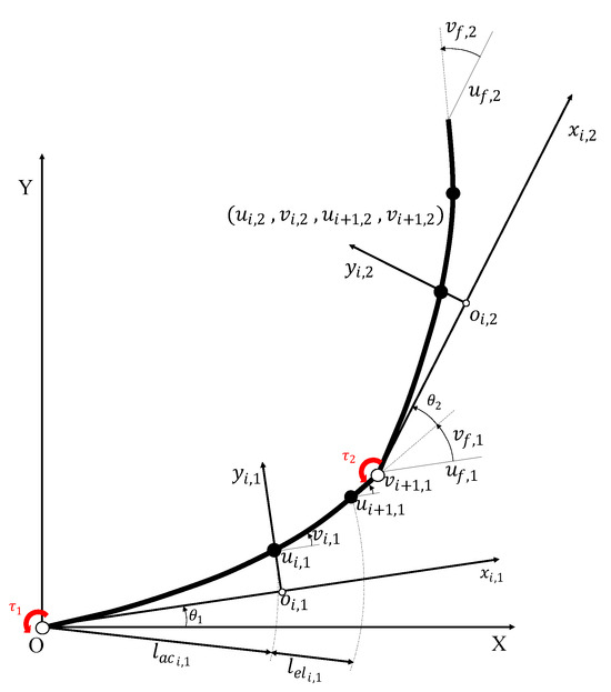
Figure 1.
A schematic of a two-link, two-joint flexible manipulator (2L2JM).

Table 1.
Properties of the cantilever beam, representing the manipulator.
The generalized element coordinates are as follows:
Using the link’s shape functions, , the coordinates can be calculated using the following equation:
where is described as follows:
where is the beam element shape function, and is described as follows:
To obtain the location of a point in the global coordinates, it is necessary to use transformation matrices as follows:
The kinetic energy for each element can be calculated as follows:
where is the beam mass density, and is the area of the element’s cross section. The element’s kinetic energy can be expressed in terms of the element mass matrix, , as follows:
The element’s potential energy can be expressed as
where is the beam element stiffness matrix, expressed as follows [30]:
The total kinetic and potential energies of the manipulator are obtained based on the components as follows:
The boundary conditions are as follows:
By applying the boundary conditions in (14), four generalized coordinates are eliminated. The new generalized coordinates are then as follows:
Based on the Lagrange method, the equation of motion can be obtained as follows:
where is the vector of external forces. It is notable that in the analytical dynamic equations, the obtained Coriolis and gravity effects are part of Equation (16); however, using FEA, which is a purely numerical approach, the equation of motion can then be written as follows:
where and are mass and stiffness matrices for the manipulator. Using Equation (17), one can obtain the state-space model of the manipulator to control its tip vibration. The state-space representation based on principal coordinates and model reduction is explained in [18]. It is noteworthy that in vibration analysis, the matrices and are symmetric and positive definite; thus, all the eigenvalues (natural frequencies) are real and positive [31].
3. Model of Two-Link, Two-Joint Flexible Manipulator (Using FEA-A)
The results of the FEA-A, including the natural frequencies and mode shapes, were used for modeling and vibration control of the manipulators. To justify the FEA-A modal results, they were compared with the manual modal analysis from Section 2 in Appendix C.
The manipulator considered has a rectangular cross-section for both links, and its properties are presented in Table 1. It is also restricted to movement in the x-y horizontal plane, meaning without gravitation. Table 2 shows a comparison of the two models.

Table 2.
The natural frequencies for the 2L2JM two models (manual FEA vs. FEA-A) for different numbers of elements.
Based on the results presented in Table 2, the Convergence Change% for the eighth mode for the manual FEA of the 2L2JM with 6 and 10 elements/link is only [(275.5 − 272.5)/275.5 = 1.09%], which is the change in the natural frequency (eigenvalue); this is also an indication of convergence of FEA for this geometry. Similarly, the Convergence Change% for the eighth mode for the FEA-A with 37 and 100 elements/link is [(266.6 − 266.7)/266.6 = 0.038%], which is the change in natural frequency (eigenvalue); this is also an indication of convergence of FEA for this geometry. Given the natural frequency of the eighth mode for the manual FEA with 6 elements, and the natural frequency of the eighth mode for the FEA-A with 37 elements, the difference is about ((275.5 − 266.6)/275.5 = 3.23%). This is a small acceptable difference; thus, the two FEA approaches can be considered verified. Thus, the eigenvectors of the FEA-A with 37 elements/link were selected for the state-space model. For FEA-A, the beam element used was BEAM188, which is a 3-D, two-node element. For the first joint, CONTA175 (2-D/3-D Node-to-Surface Contact element) was used. For the joint between two links, the element MPC184 (revolute joint with zero stiffness and damping) was used. To define the boundary of a deformable body associated with contact elements, TARGE170 was used.
For dynamic problems, master DOFs are typically chosen as displacements of nodes with higher rotations, and nodes associated with elements with a higher mass moment of inertia. On the other hand, the slave degrees of freedom are the displacements and rotations of nodes with relatively low mass moment of inertia [26]. These nodes are chosen from the geometry after meshing has been performed. These DOFs contain the main dynamic characteristics of the system, so that the relative displacement of these DOFs is sufficient to show the dynamic behavior of the system. The inputs and outputs of the system are the necessary master DOFs; however, other DOFs could also be chosen for more accurate modeling. For the 2L2JM, the eigenvectors include the relative displacements of the four master DOFs (shown with thick arrows in Figure 2): the linear displacement of the tip and the actuator, plus the rotational displacement of the joints. These joints’ torque/force represents the actuators’ torque/force for vibration suppression. Also, it is assumed that there is a nodal force on the point at L/3 of the first link to produce a linear disturbance force.

Figure 2.
Master DOFs of the 2L2JM.
The full state-space model includes all 20 eigenvectors of the manipulator extracted from FEA-A. They are processed using Appendix A to obtain a reduced model. The Truncated model includes the first four modes of vibration, i.e., it has the first eight columns and the first eight rows of the full state-space model. However, for the Balanced-Matched-DC (BMDC, reduction algorithm model), first, the full-order model without the rigid modes is balanced, and then the balanced-oscillatory model is reduced to keep only two modes. Finally, the two rigid modes are attached, resulting in a model with four modes. According to Appendix A, after sorting the controllability and observability Gramians, modes with higher values, which indicate a greater influence on the system’s dynamics, are retained.
4. Results
Different state-space models of the manipulator were compared with the transient module of FEA-A. The responses of these open-loop models to an arbitrary vibration under the same condition are shown in Figure 3.
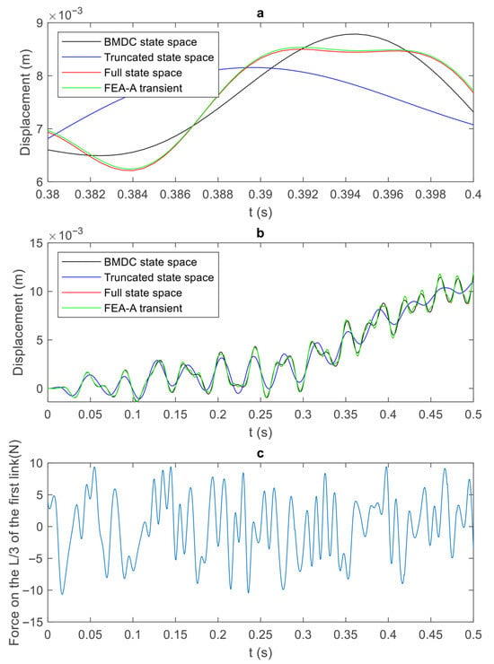
Figure 3.
Simulation results for the 2L2JM’s tip displacement and the moment for 3 different state-space models, as well as the FEA-A transient. (a) The response for a small interval (0.38–0.4), (b) the response for a 0–0.5 s interval, and (c) an arbitrary excitation force between [−10,10] N applied at L/3 of the first link.
As shown in Figure 3a,b, the curves “FEA-A transient” and “Full state space” are almost identical. This proves that the full-order mathematical model with a state matrix of 40 by 40 generates similar results to the FEA-A. This indicates the accuracy of the full-order model with only four master DOFs and 20 modes. More significantly, the results of the BMDC model with a state matrix of eight by eight are very close to the FEA-A results. This indicates the accuracy and efficiency of the BMDC with only four master nodes and four modes. Here, since the manipulator has more complex geometry than a cantilever beam, the balancing effect is obvious between BMDC and the Truncated algorithms. The difference index of the models is represented by the normalized RMS as follows:
where is the difference in the tip displacement between any of the state-space models and the FEA-A transient (reference model). Parameters and are the th variable and the total number of variables, respectively. The RMS values are normalized with respect to the maximum value, which was obtained from the worst model. These maximum values for the full-order state space, BMDC, and the Truncated model are 0.0471, 0.2612, and 1, respectively.
Although the example presented involves a simple geometry with a constant rectangular cross-section, the validated results can easily be extended to more complex geometries, i.e., manipulators with varying cross-sections; the state-space models are modelled using eigenvectors generated in FEA-A.
After the state-space models were verified, they were used to create a closed-loop system. The controller system for active vibration suppression was a H-∞ controller, which is explained in Appendix B. The simulations were conducted on four different systems; full-order open-loop (FOL); full-order closed-loop, including 40 modes of vibration (FCL); reduced-order open-loop including four modes of vibration (ROL); and reduced-order closed-loop (RCL). For the reduced models, only BMDC was used. The closed-loop model was designed based on an H-∞ controller, and the weight functions were chosen by trial and error. This controller was designed based on “hinfsyn” in MATLAB. The second group of graphs is Bode plots, shown later, to compare the models with regard to the frequency domain.
Figure 4 compares the full-order open-loop (FOL) and full-order closed-loop (FCL) models in the presence of an arbitrary vibration. The FCL curve in Figure 4a illustrates that the tip of the manipulator fluctuates around the origin when the controller is active, which proves the successful performance of the controller. A typical performance index for vibration control is to reduce the magnitude of the tip vibration to about 10% of the extended length of the manipulator. For the 2 m long 2L2JM, this is about 0.2 m. However, since the purpose of the manipulator vibration control is to enable steady data collection, this index was set to 0.005 m. In other words, the controller was set to keep the displacement of the tip below 5 mm. The deviation of the FOL is due to the rigid modes of the manipulator. Figure 4b shows the zoomed-in FCL performance. It shows that the controller reduces the tip vibrations to a range of [−4,4] mm. Therefore, the tip displacement of the closed loop system achieves the target performance. Figure 4c is the disturbance time series for the duration of 0.5 s. This disturbance was an arbitrary vibration intended to resemble the vibration of a rough terrain. Figure 5 shows the controller effort, i.e., the amount of moment produced by the joints to attenuate the vibration. The controller effort shows how the controller achieves the desired performance. In the 2L2JM, the joint torques were applied within [−2,2] Nm. Using this value, one can provide suitable actuators in a real experiment.
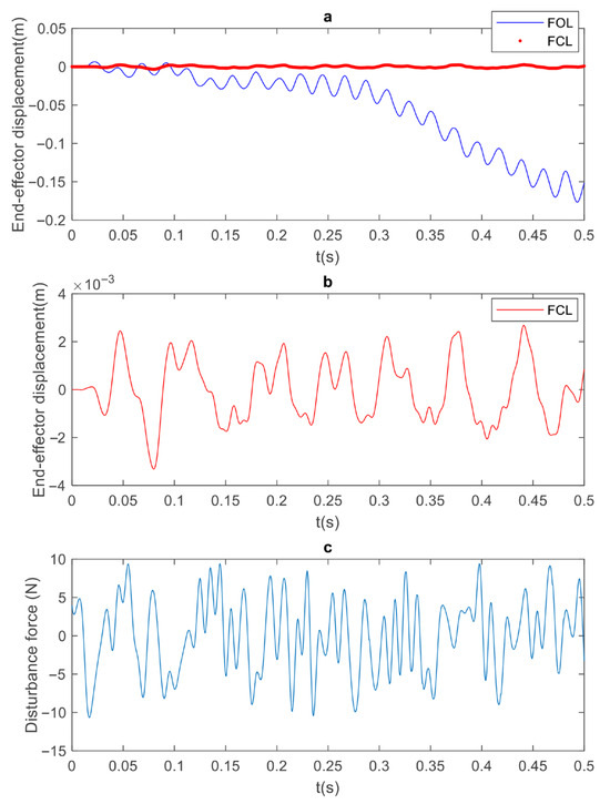
Figure 4.
Simulation results for 2L2JM: (a) tip displacement of full-order open-loop (FOL) and full-order closed-loop (FCL) models; (b) zoomed (FCL) tip displacement; (c) disturbance due to arbitrary vibration [−10,10] N, with linear force exerted at x = L/3 of first link.
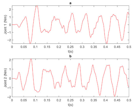
Figure 5.
Joint torques (controller effort) for 2L2JM full-order model: (a) joint 1, (b) joint 2.
Figure 6 is like Figure 4, but compares the reduced-order open-loop (ROL, BMDC with four modes) and reduced-order closed-loop (RCL) models in the presence of the arbitrary vibration. Again, the RCL curve in Figure 6a illustrates that the tip of the manipulator fluctuates around the origin when the controller is active, which proves the successful performance of the controller. The target performance of the controller was set to keep the displacement of the tip below 5 mm. Figure 6b shows the zoomed-in closed-loop performance. It shows that the controller reduces the tip vibrations to the range of [−4,4] mm. Therefore, the tip displacement of the closed-loop system achieves the target performance. Figure 6c is the disturbance time series for a duration of 0.5 s.
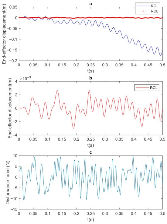
Figure 6.
Simulation results for 2L2JM: (a) tip displacement of reduced-order open-loop (ROL) and reduced-order closed-loop (RCL) models; (b) zoomed RCL tip displacement; (c) disturbance due to arbitrary vibration [−10,10] N, with linear force exerted at x = L/3 of first link.
Figure 7 shows the controller’s effort, i.e., the amount of force that is produced by the joints to attenuate the vibration. Comparing Figure 5 and Figure 7, it can be seen that the actuators apply a torque in the range of [−2,2] Nm. This indicates that, using the reduced model, one can choose suitable actuators for vibration suppression of the manipulator.
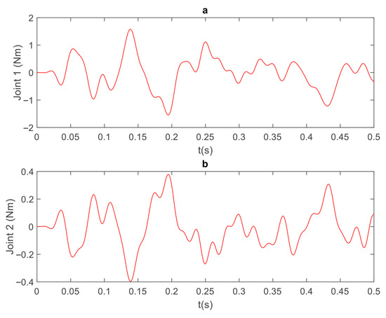
Figure 7.
Joint torques (controller effort) for 2L2JM RCL model: (a) joint 1, (b) joint 2.
The effectiveness index of the controller is specified by the H-∞ norm of the system. Based on its definition, “It describes the maximum energy gain of the system and is decided by the peak value of the largest singular value of the frequency response matrix over the whole frequency axis” [32]. It is defined as follows:
where is the system transfer function, which could be the overall closed-loop system or the open-loop system. In the definition of the H-∞ norm of the system in Equation (19), stands for the second norm, which is defined as follows:
The effectiveness of the controllers for the full-order and reduced-order models is shown in Figure 8.
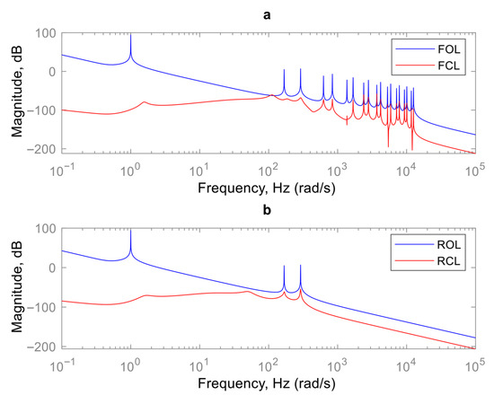
Figure 8.
Simulation results: Bode diagrams of 2L2JM (a) full-order open-loop and closed-loop systems, and (b) reduced-order closed-loop and open-loop systems.
The 2L2JM model is an MIMO system. Considering Equation (19), the H-∞ norm for an MIMO system is the largest singular value of the system (open-loop or closed-loop) across frequencies. The Bode diagrams are shown in Figure 8; Figure 8a illustrates that the H-∞ controller has reduced the H-∞ norm of the full-order system from infinity to −58.2 dB. Furthermore, in Figure 8b, the controller has reduced the H-∞ norm of the reduced-order system (BMDC with four modes) from infinity to −54.2 dB. This infinite value is due to the rigid modes of the manipulator. These modes are not shown in the figure, since they occur at a frequency of 0 Hz.
5. Conclusions
A flexible five-degree-of-freedom (5-DOF) manipulator was developed for integration with a mobile rover designed to monitor crops in agricultural fields. During field navigation, the manipulator experiences vibrations that compromise the accuracy of data collected by its end-effector (EE), which houses multiple sensors. This study aimed to evaluate the vibration characteristics of the 5-DOF manipulator, implement control strategies to mitigate these vibrations, and develop controllers to attenuate tip oscillations. Modal parameters—including natural frequencies and mode shapes—were extracted, and the vibrational forces transmitted from the mobile base to the EE were quantified. Using manual Finite Element Analysis (FEA), the equations of motion for a two-link, two-joint manipulator (2L2JM) were derived. The eigenvectors obtained from FEA-A were then used to construct both full-order and reduced-order state-space models of a cantilever beam, the 2L2JM, and the 5-DOF manipulator.
Finite Element Analysis (FEA) was employed to extract the eigenvalues (natural frequencies) and corresponding eigenvectors (mode shapes) of a two-link, two-joint manipulator (2L2JM), representing a flexible-link robotic system. To facilitate controller design, balanced realization and Match-DC-Gain model reduction algorithms were applied to reduce the full-order eigenvector model to a computationally efficient reduced-order representation. An H-infinity controller was implemented to suppress tip vibrations of the manipulator. Simulation analyses were conducted across four configurations: (1) full-order open-loop, (2) full-order closed-loop, (3) reduced-order open-loop, and (4) reduced-order closed-loop systems. The selected H-infinity controller demonstrated effective performance in mitigating tip vibrations in response to external disturbances. Furthermore, the reduced-order model, derived via balanced realization, exhibited dynamic behavior closely matching that of the full-order system. A key contribution of this research is the validation of the reduced-order analytical model using FEA. Model reduction is essential for practical vibration control, as full state-space representations typically result in high-dimensional matrices. The integration of state-space modeling and reduction techniques for vibration control of the 2L2JM constitutes a novel aspect of this study.
Author Contributions
A.M.K.: planned and carried out modeling; analysis and simulation verification. R.F.: supervised the research; provided funding; advised on the simulation analysis; provided extensive technical and editorial comments and re-wrote and edited the manuscript. All authors have read and agreed to the published version of the manuscript.
Funding
This work was supported by NSERC-CRD grant no. 514648-17 of Reza Fotouhi, and by an industrial partner.
Data Availability Statement
Data are available on request from the authors. The data are not publicly available due to “readers may not have license to use ANSYS”.
Conflicts of Interest
The authors declare no conflict of interest.
Glossary
| List of abbreviations | |
| 2L2JM | Two-link, two-joint-manipulator |
| BMDC | Balanced-Matched-DC (reduction algorithm) |
| DOF | Degree-of-freedom |
| EE | End-effector |
| FEA-A | Finite Element Analysis through ANSYS |
| FLM | Flexible-link manipulator |
| I/O | Input and output |
| LQR | Linear quadratic regulator |
| MIMO | Multi-input–multi-output |
| List of symbols | |
| ζ | Damping coefficient |
| Joint angle of link | |
| ρ | Density |
| Hermit shape function | |
| ω | Excitation frequency |
| natural frequency | |
| A | State matrix |
| Ã | Transformed state matrix |
| B | Input matrix |
| B̃ | Transformed input matrix |
| C | Output matrix |
| C̃ | Transformed output matrix |
| D | Feed-forward matrix |
| E | Modulus of elasticity |
| Ele | Element |
| F | External moment |
| G | Plant transfer function |
| K | Global stiffness matrix |
| element | |
| Controller transfer function | |
| L | Link total length |
| M | Global Mass matrix |
| element | |
| P | Generalized system transfer function |
| Q | State weighting function |
| R | Input weighting function |
| S | Sensitivity transfer function |
| T | Gramian transformation matrix (in Appendix A) |
| U | Input control vector (in Appendix A) |
| V | Solution of Riccati equation |
| Controllability Gramian | |
| Observability Gramian | |
| Sensitivity weighting function | |
| Actuator weighting function | |
| X | State vector |
| Y | Output vector |
| nth mode shape | |
| Modal matrix | |
| Cross-section area | |
| b | Base displacement |
| Damper constant | |
| e | End-effector displacement |
| Final node of each link | |
| Number of outputs | |
| Number of inputs | |
| Number of a node | |
| Imaginary unit (sqrt (−1)) | |
| Spring stiffness | |
| Accumulated length, or distance from base to point (x, y) | |
| Length of element | |
| Number of links for two-link manipulator | |
| Point mass | |
| Number of degrees of freedom | |
| Location of a node on undeformed link | |
| Generalized coordinate | |
| element | |
| Laplace complex variable | |
| Time | |
| Displacement of node | |
| Slope of node | |
| element fixed to undeformed link | |
| axis (cantilever) | |
| axis (two-link manipulator) | |
| element fixed to undeformed link | |
| axis (cantilever) | |
| axis (two-link manipulator) | |
| element’s generalized coordinate | |
| principal coordinate | |
Appendix A. Balancing and Model Reduction
Designing a controller requires knowing the I/O relationship (input and output) of the system. Given the full-order state space, the linear I/O relationship of the system is as follows:
where A, B, C, and D are called state, input, output, and feedthrough matrices, respectively. Furthermore, , and are the vectors of the input and output.
If , then the state matrix is as follows:
and the input matrix is as follows:
where is the number of nodes that input forces are exerted on. The output matrix is as follows:
where is the number of output nodes. To reduce the model of the system, balanced realization is proposed. Balancing arranges the model based on the contribution of the states to I/O. This method is based on controllability and observability Gramians, which identify the amount of controllability and observability of the states. The controllability and observability Gramians are defined as , and , respectively [33]:
For infinite time, the Gramians would be referred to as , and . If the eigenvalue problem is solved for the controllability Gramian,
and the eigenvalues are sorted from biggest to the smallest, then the eigenvector corresponding to the biggest eigenvalue is the most controllable direction in the state-space coordinate. Similarly, observability can be sorted to show the most observable direction. There is a special coordinate transformation that makes both Gramians equal and diagonal. If and it is substituted into Equation (A1), the transformed state-space system is as follows:
where is the state vector in an order that both observability and controllability Gramians are equal and diagonal.
In a simpler notation, one can rewrite the following equations:
Then, the Gramians become the following:
By multiplying the Gramians as follows:
and assuming , then Equation (A12) becomes an eigenvalue problem:
Solving Equation (A13) results in the transformation and the values that represent the equal and diagonal controllability and observability Gramians.
After sorting based on the biggest to lowest values of , we can truncate the transformed system to keep the modes with significant contribution to the past input and future output energy of the system. This can be achieved by partitioning the full state vector to , where and are the state variables to keep and to remove, respectively. Then, Equation (A9) becomes the following system [27]:
In order to eliminate the fast-dynamics or high-frequency modes, we set . This reduction is called the Balanced-Match-DC-gain model reduction algorithm, or BMDC [27]. Then, Equation (A14) turns into the reduced system as follows:
The system of Equation (A15) is the reduced state-space representation of the system, i.e., this system contains the states that make a significant contribution to the past input and future output energy of the system. Thus, it has less computational cost for the controller.
Appendix B. H-∞ Controller for Vibration Damping of Manipulators
The 2L2JM is recognized as an MIMO system, since it has two inputs and one output. To deal with MIMO systems, an H-∞ controller is proposed. This controller achieves a compromise between different controlling objectives by solving an optimization problem. The objectives can be trajectory tracking, actuator performance, disturbance control, and noise control [32].
This section is devoted to explanation of H-∞ controller concept. According to [32], a closed-loop feedback system, as shown in Figure A1, is internally stable if and only if all the transfer functions in Equations (A16)–(A19) are stable, i.e., bounded-input bounded-output (BIBO). This happens when the transfer functions have two conditions: first, the denominator has a higher order than the numerator; second, the poles are on the left-hand plane of the S-space.
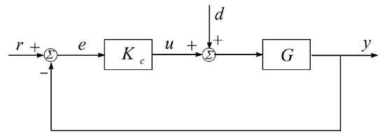
Figure A1.
A closed-loop system with feedback [32]. The parameters are r: reference, e: error, u: control input, d: disturbance, y: output, : controller transfer function, G: plant transfer function, I: Identity matrix, and s: Laplace variable.
If the nominal system is internally stable, it can meet the required performance (nominal performance). The ability for tracking is defined by the transfer function from to .
This transfer function is called sensitivity, and it is represented by S. To have good tracking performance in a certain frequency , the sensitivity magnitude should be less than a small positive value:
The inequality can be normalized with a weighting function :
This inequality over the entire frequency domain can be expressed as follows:
where stands for the infinity norm, which is defined as follows:
The infinity norm of a system is also called the norm of the system. It describes the maximum energy gain of the system, and is decided by the peak value of the largest singular value of the frequency response matrix over the whole frequency axis [32]. This ensures that the system at any frequency can track the reference trajectory.
In the definition of the norm in Equation (A24), stands for the second norm, which is defined as follows:
Similarly, for efficient actuator performance, the transfer function in (A19) should be as follows:
The H-∞ controller is a multi-objective controller that solves an optimization problem for different control criteria. Therefore, the inequalities (A23) and (A26) can be written as follows:
For better demonstration, Figure A1 can be shown in the following standard configuration.
According to Figure A2, denotes external inputs such as the reference, noise, and disturbance. On the other hand, denotes the output signals to be minimized. The objective is to find a stable controller to minimize the output . The generalized system matrix is defined as follows:
By substituting into the system of Equation (A28) and removing y, one can end up having z as
where is the lower linear fractional transformation of and . The performance index (objective) becomes
which is called the H-∞ optimization problem. The H-∞ norm is usually computed numerically from a state-space realization. The smallest value of is found so that the Hamiltonian matrix Equation (A31) has no eigenvalues on the imaginary axis [34]:
where A, B, C, and D, are the state-space matrices and . Thus, the main problem becomes
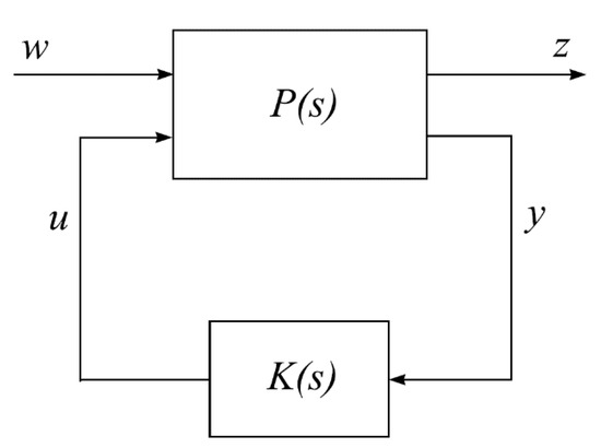
Figure A2.
The standard H-∞ configuration [32] (w: external input, z: outputs to be minimized, u: control input, y: measured output, P(s): generalized system transfer function, K(s): controller transfer function).
Appendix C. 2L2JM Mode Shapes
The 2L2JM is meshed in the FEA-A workbench, as shown in Figure A3. The properties are extracted from modal solution information. The cantilever is a line body. The elements used are BEAM188, which is a 3-D two-noded beam. The boundary condition is a hinge support at the first joint, and its element is CONTA175, which is a 2-D/3-D node-to-surface contact. The joint in the middle of the links is a revolute MPC184 with zero stiffness and damping. Moreover, TARGE170 is used to define the boundary of a deformable body associated with contact elements.
- −
- Number of total nodes = 154.
- −
- Number of solid elements = 74 (37 BEAM188 elements for each link).
- −
- Number of total elements = 81.
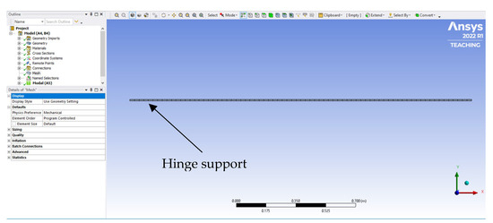
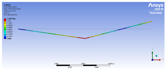
Figure A4.
The first mode of vibration for the 2L2JM (first rigid mode).
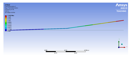
Figure A5.
The second mode of vibration for the 2L2JM (second rigid mode).
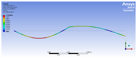
Figure A6.
The third mode of vibration for the 2L2JM.
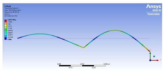
Figure A7.
The fourth mode of vibration for the 2L2JM.
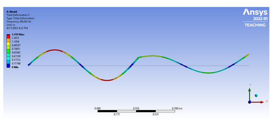
Figure A8.
The fifth mode of vibration for the 2L2JM.
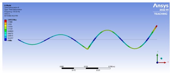
Figure A9.
The sixth mode of vibration for the 2L2JM.
References
- Burnette, M.; Kooper, R.; Maloney, J.D.; Rohde, G.S.; Terstriep, J.A.; Willis, C.; Fahlgren, N.; Mockler, T.; Newcomb, M.; Sagan, V.; et al. TERRA-REF data processing infrastructure. In Proceedings of the Practice and Experience on Advanced Research Computing, Pittsburgh, PA, USA, 22–26 July 2018; Association for Computing Machinery: New York, NY, USA, 2018; pp. 1–7. [Google Scholar]
- Phung, A.S.; Malzahn, J.; Hoffmann, F.; Bertram, T. Data based kinematic model of a multi-flexible-link robot arm for varying payloads. In Proceedings of the 2011 IEEE International Conference on Robotics and Biomimetics, Karon Beach, Thailand, 7–11 December 2011; IEEE: New York, NY, USA, 2011; pp. 1255–1260. [Google Scholar]
- Malzahn, J. Modeling and Control of Multi-Elastic-Link Robots under Gravity: From Oscillation Damping and Position Control to Physical Interaction. Ph.D. Dissertation, Dortmund Technische Universität, Dortmund, Germany, 2014. [Google Scholar]
- Njeri, W.; Sasaki, M.; Matsushita, K. Gain Tuning for High-Speed Vibration Control of a Multilink Flexible Manipulator Using Artificial Neural Network. J. Vib. Acoust. 2019, 141, 041011. [Google Scholar] [CrossRef]
- Meng, T.; He, W. ILC for a Flexible Single-Link Manipulator. In Iterative Learning Control for Flexible Structures; Springer: Princeton, NJ, USA, 2020; pp. 109–128. [Google Scholar]
- Meng, T.; He, W. Iterative learning control of a robotic arm experiment platform with input constraint. IEEE Trans. Ind. Electron. 2017, 65, 664–672. [Google Scholar] [CrossRef]
- Jamali, A.; Mat Darus, I.Z.; Mohd Samin, P.P.; Tokhi, M.O. Intelligent modeling of double link flexible robotic manipulator using artificial neural network. J. Vibroengineering 2018, 20, 1021–1034. [Google Scholar] [CrossRef]
- Jamali, A.; Darus, I.M.; Tokhi, M.O.; Abidin, A.Z. Utilizing P-type ILA in tuning hybrid PID controller for double link flexible robotic manipulator. In Proceedings of the 2018 2nd International Conference on Smart Sensors and Application (ICSSA), Kuching, Malaysia, 24–26 July 2018; IEEE: New York, NY, USA, 2018; pp. 141–146. [Google Scholar]
- Benosman, M. Model-Based Vs Data-Driven Adaptive Control: An Overview. Int. J. Adapt. Control Signal Process. 2018, 32, 753–776. [Google Scholar] [CrossRef]
- Pereira, E.; Aphale, S.S.; Feliu, V.; Moheimani, S.R. Integral Resonant Control for Vibration Damping and Precise Tip-Positioning of a Single-Link Flexible Manipulator. IEEE/ASME Trans. Mechatron. 2010, 16, 232–240. [Google Scholar] [CrossRef]
- Qingsheng, L.; Xiang, L. Research of the Active Vibration Suppression of Flexible Manipulator with One Degree-of-Freedom. In Proceedings of the International Conference on Intelligent Robotics and Applications, Wuhan, China, 16–18 August 2017; Springer: Cham, Switzerland, 2017; pp. 624–636. [Google Scholar]
- Fareh, R. Sliding mode fractional order control for a single flexible link manipulator. Int. J. Mech. Eng. Rob. Res. 2019, 8, 228–232. [Google Scholar] [CrossRef]
- Reddy, M.P.P.; Jacob, J. Vibration control of flexible link manipulator using SDRE controller and Kalman filtering. Stud. Inform. Control 2017, 26, 143–150. [Google Scholar]
- Qiu, Z.C.; Han, J.D.; Liu, J.G. Experiments on fuzzy sliding mode variable structure control for vibration suppression of a rotating flexible beam. J. Vib. Control 2015, 21, 343–358. [Google Scholar] [CrossRef]
- Nestorović, T.; Durrani, N.; Trajkov, M. Experimental model identification and vibration control of a smart cantilever beam using piezoelectric actuators and sensors. J. Electroceramics 2012, 29, 42–55. [Google Scholar] [CrossRef]
- Shen, X.; Dai, Y.; Chen, M.; Zhang, L.; Yu, L. Active vibration control of the sting used in wind tunnel: Comparison of three control algorithms. Shock Vib. 2018, 2018, 1905049. [Google Scholar] [CrossRef]
- Theodore, R.J.; Ghosal, A. Comparison of the assumed modes and finite element models for flexible multilink manipulators. Int. J. Rob. Res. 1995, 14, 91–111. [Google Scholar] [CrossRef]
- Kamalirad, A.M.; Fotouhi, R.; Taghizadeh, M. Vibration Control of a Cantilever Beam Using Reduced Model. In Proceedings of the ASME International Mechanical Engineering Congress and Exposition, Columbus, OH, USA, 30 October–3 November 2022; ASME: New York, NY, USA, 2022; Volume 86670, p. V005T07A034. [Google Scholar]
- Karagülle, H.; Malgaca, L.; Dirilmiş, M.; Akdağ, M.; Yavuz, S. Vibration control of a two-link flexible manipulator. J. Vib. Control 2017, 23, 2023–2034. [Google Scholar] [CrossRef]
- Dubay, R.; Hassan, M.; Li, C.; Charest, M. Finite element based model predictive control for active vibration suppression of a one-link flexible manipulator. ISA Trans. 2014, 53, 1609–1619. [Google Scholar] [CrossRef] [PubMed]
- Shao, M.; Huang, Y.; Silberschmidt, V.V. Intelligent manipulator with flexible link and joint: Modeling and vibration control. Shock Vib. 2020, 2020, 4671358. [Google Scholar] [CrossRef]
- Khot, S.M.; Khan, Y. Simulation of active vibration control of a cantilever beam using LQR, LQG and H-∞ optimal controllers. J. Vibr. Anal. Meas. Control 2015, 3, 134–151. [Google Scholar]
- Ali, A.A.; Lateef, R.A.R.; Saeed, M.W. Intelligent tuning of vibration mitigation process for single link manipulator using fuzzy logic. Eng. Sci. Technol. Int. J. 2017, 20, 1233–1241. [Google Scholar] [CrossRef]
- Kamel, M.A.; Ibrahim, K.; Ahmed, A.E.-M. Vibration control of smart cantilever beam using finite element method. Alex. Eng. J. 2019, 58, 591–601. [Google Scholar] [CrossRef]
- Ebrahimi-Tirtashi, A.; Mohajerin, S.; Zakerzadeh, M.R.; Nojoomian, M.A. Vibration control of a piezoelectric cantilever smart beam by 1 adaptive control system. Syst. Sci. Control Eng. 2021, 9, 542–555. [Google Scholar] [CrossRef]
- Hatch, M.R. Vibration Simulation Using MATLAB and ANSYS; CRC Press: Boca Raton, FL, USA, 2000. [Google Scholar]
- Reddy, Y.; Hur, S. Comparison of Optimal Control Designs for a 5 MW Wind Turbine. Appl. Sci. 2021, 11, 8774. [Google Scholar] [CrossRef]
- Kamalirad, A.M. Active Vibration Control of a Flexible Robotic Manipulator. Master Thesis, University of Saskatchewan, Saskatoon, SK, Canada, 2023. [Google Scholar]
- Zhu, Y.; Qiu, J.; Tani, J. Simultaneous optimization of a two-link flexible robot arm. J. Robot. Syst. 2001, 18, 29–38. [Google Scholar] [CrossRef]
- Tirupathi, R.C.; Ashok, D.B. Introduction to Finite Elements in Engineering; Cambridge University Press: Cambridge, UK, 2016. [Google Scholar]
- Singiresu, S.R. Mechanical Vibrations; Addison Wesley: Boston, MA, USA, 1995. [Google Scholar]
- Gu, D.-W.; Petkov, P.; Konstantinov, M.M. Robust Control Design with MATLAB®; Springer Science & Business Media: London, UK, 2005. [Google Scholar]
- Brunton, S.L.; Kutz, J.N. Data-Driven Science and Engineering: Machine Learning, Dynamical Systems, and Control; Cambridge University Press: Cambridge, UK, 2022. [Google Scholar]
- Wang, H.; Xing, Y.; Li, Y.; Li, Z. Dynamic modeling of five-bar manipulator with structurally flexible linkages. In Proceedings of the 2010 8th World Congress on Intelligent Control and Automation, Jinan, China, 7–9 July 2010; IEEE: New York, NY, USA, 2010; pp. 5774–5779. [Google Scholar]
Disclaimer/Publisher’s Note: The statements, opinions and data contained in all publications are solely those of the individual author(s) and contributor(s) and not of MDPI and/or the editor(s). MDPI and/or the editor(s) disclaim responsibility for any injury to people or property resulting from any ideas, methods, instructions or products referred to in the content. |
© 2025 by the authors. Licensee MDPI, Basel, Switzerland. This article is an open access article distributed under the terms and conditions of the Creative Commons Attribution (CC BY) license (https://creativecommons.org/licenses/by/4.0/).