Article

Influence of Random Parametric Errors on Nonlinear Dynamic Behaviors of a Laminated Composite Cantilever Beam

School of Environmental and Safety Engineering, Liaoning Petrochemical University, Fushun 113001, China
*
Author to whom correspondence should be addressed.
Vibration 2025, 8(4), 57; https://doi.org/10.3390/vibration8040057
Submission received: 1 July 2025 / Revised: 19 September 2025 / Accepted: 23 September 2025 / Published: 29 September 2025

Abstract

For the first time, the influence of random parametric errors (RPEs) on the nonlinear dynamic behaviors of a laminated composite cantilever beam (LCCB) is studied. A nonlinear dynamic model for the LCCB is first established based on Hamilton’s principle. In a numerical simulation, four different cases are presented to analyze the dynamic behavior of the studied LCCB. This study reveals that varying RPE levels cause significant changes in the dynamic response of the LCCB. The results indicate that RPE not only induces a transition from a periodic to a chaotic behavior but may also alter the maximum amplitude of chaotic vibrations, providing a critical theoretical basis for incorporating uncertainty factors in engineering design.

1. Introduction

Composite materials are novel materials with superior performance, created by combining two or more materials featuring different properties. Compared to traditional materials, composite materials possess the advantages of high strength and low density, making them widely used in the aerospace engineering [1], railway field [2], and construction field [3]. Composite materials have become the primary materials for various high-performance cantilever structures. However, in practical applications, these beams are inevitably affected by random factors, which may lead to significant changes in the vibrations of cantilever structures and thereby affect their stability and safety. In particular, structural parameters such as stiffness, damping, and geometric properties may experience random fluctuations due to manufacturing imperfections, environmental influences, or operational uncertainties. Therefore, RPEs are introduced to investigate the changes in the nonlinear dynamic behavior of the cantilever structure of laminated composite materials, providing theoretical support for studying the vibration response of the cantilever structure.
Composite structures are widely applied, and in recent decades researchers have conducted extensive studies on their dynamic behavior. Djojodihardjo et al. [4] solved the cantilevered Euler-Bernoulli beam with a spring-loaded free end and conducted a study using three different configurations of piezoelectric cantilever beams as examples. They developed an effective analytical method for the vibration analysis of Euler-Bernoulli beams. Filippi et al. [5], also within the framework of linear structures, proposed an advanced kinematic plate or shell model for evaluating the dispersion characteristics of two-dimensional waveguides and analyzed the wave propagation properties of 2D waveguides. The team [6] then examined the influence of geometric nonlinearity on wave propagation in three different structural forms of beams. Liu et al. [7] investigated the vortex-induced vibration dynamic behavior of flexible LCCB in water flow. By employing the nonlinear higher-order shear deformation theory and the von Kármán strain, they focused on analyzing the effects of fiber orientation, inflow velocity, and geometric nonlinearity on the vibration characteristics of the beam, providing explanations for various dynamic phenomena. Zhang et al. [8] studied a Euler-Bernoulli-beam based LCCB and analyzed its chaotic behaviors using the global perturbation method. Under certain conditions, the nonlinear non-planar vibration of the cantilever beam exhibits different forms of chaotic responses. Bouadjadja et al. [9] developed an analytical model grounded in Euler-Bernoulli beam theory, applicable to both symmetric and asymmetric laminated cantilever structures. Its effectiveness in analyzing static large deflections was experimentally validated. These studies mainly focused on classical Euler-Bernoulli beam models, offering important insights into fundamental vibration and wave propagation characteristics of composite structures.
To more accurately capture the structural response, researchers have developed more refined beam models. In this context, the Timoshenko beam theory, which accounts for first-order shear deformation, has been widely applied in the dynamic analysis of composite beams. Fu et al. [10] derived the governing equations of symmetric laminated composite beams based on the first-order shear deformation beam theory (Timoshenko beam) using Hamilton’s principle. They proposed both analytical and numerical solutions and investigated the effects of different transverse shear effects and boundary conditions on thermal buckling and post-buckling behavior. Viet et al. [11] proposed a novel analytical model based on Timoshenko beam theory to investigate the dynamic behavior of shape memory alloy (SMA) LCCBs subjected to a concentrated tip load. Their findings revealed that temperature and stiffness affect the cantilever beam’s deformation. Preethi et al. [12] employed Timoshenko beam theory while considering the effects of surface stress and formulated the nonlocal nonlinear equations for non-uniform rotating laminated nano-cantilever beams. They investigated the nonlinear bending and free vibration behavior of the nano-cantilever beam. These studies demonstrate that the first-order shear deformation theory is well-suited for capturing the dynamic responses of moderately thick and size-sensitive structures.
Building upon this foundation, researchers have further developed higher-order theoretical models that incorporate stronger nonlinear effects and coupling mechanisms to investigate complex phenomena such as chaotic vibrations, bifurcations, and multi-physical field interactions. Zhang et al. [13] formulated nonlinear equations for composite laminated piezoelectric cantilever plates under combined transverse and in-plane excitations. They investigated the nonlinear dynamic response of the composite piezoelectric cantilever plate under the combined action of transverse and in-plane excitations and found that the system exhibits both periodic and chaotic motions. Guo et al. [14] constructed a nonlinear dynamic model for macrofiber composite (MFC) laminated shells, examining the influence of the electric field, external excitation, and nonlinear parameters on system stability. A comprehensive analysis of chaotic and periodic motions was performed, revealing that both the electric field and external excitation significantly impact the structure’s dynamic response. Li et al. [15] introduced the dynamic stiffness method to study the effects of parameters such as end conditions on the natural frequencies of composite beams. Amabili et al. [16] developed a two-dimensional system based on the third-order shear deformation theory for the nonlinear vibration of cantilever beams, retaining rotational inertia, in-plane, and rotational nonlinearities. They analyzed the nonlinear response of self-healing composite cantilever beams and verified theoretical-experimental consistency across five excitation levels. Zhang et al. [17] investigated the nonlinear dynamic behavior of laminated composite cantilever rectangular plates with shear deformation under planar and moment excitations. Using numerical simulations, they discovered the presence of chaotic response of the system. They also investigated the effects of different excitation amplitudes on the nonlinear vibration of the laminated composite cantilever rectangular plate. Guo et al. [18] investigated the dynamic behavior of graphene-enhanced laminated composite cantilever plates. The numerical results revealed that the dynamic behavior of the system includes periodic, jump, and chaotic motions. Liu [19] developed a two-dimensional dynamic model for axially moving LCCBs based on Reddy’s third-order shear deformation theory. They investigated the complex nonlinear dynamic behavior and analyzed the effects of different parameters on the displacement amplitude and frequency at the beam’s end. Liu and Sun [20] considered the influence of the third-order shear effect on beam vibration while establishing a two-dimensional nonlinear dynamic system for LCCBs. They conducted a numerical simulation to analyze the chaotic vibration of the LCCBs. Liu and Ma [21] investigated the influence of aerodynamic forces, piezoelectric excitation, and in-plane excitation on the dynamic behavior of a two-dimensional laminated composite cantilever plate, based on Reddy’s higher-order shear deformation theory. Their study revealed how the system evolves from a stable state to chaotic behavior under different flow velocities. Sun et al. [22]. established one-dimensional geometrically nonlinear and linear substrate models to investigate the influence of substrate geometric nonlinearity on the average output power of a hybrid galloping energy harvester with a vertically aligned D-shaped bluff body. The results showed significant differences in energy output and dynamic response between the two models, indicating that the effect of substrate geometric nonlinearity cannot be neglected in such systems. In the aforementioned studies, although nonlinear dynamic behavior has received extensive attention, the influence of random factors such as RPEs on the dynamic behavior of LCCBs has not been explored.
The influence of parametric uncertainty on the behavior and stability of nonlinear dynamic systems has been widely investigated. In 2007, Kuo [23] proposed an adaptive fuzzy sliding mode control (FSMC) to control the chaotic responses in the Sprott chaotic system, which is subjected to parametric variations. In 2009, Ablay [24] found that parametric uncertainties could cause the chaotic system to deviate from the desired trajectory and affect its stability. In the following years, researchers have attempted to incorporate random parameter errors directly into the dynamic modeling of physical systems in order to more accurately reflect the real-world effects of stochastic factors. Shirazi et al. [25,26,27,28,29] incorporated parameter errors into the modeling of chaotic systems with measurement noise, atomic force microscopes, microelectromechanical systems, and electrostatically actuated nanobeams. Recently, the influence of RPEs on the dynamic response of engineering structures has attracted increasing attention from researchers. Youssef and Ayman [30] numerically studied the chattering phenomenon of a twin-tailed fighter aircraft, and it was found that uncertain parameters could lead to bifurcations and jump phenomena in the nonlinear dynamic of aircraft tails. In the next year, Hao et al. [31] formulated the dynamic equations for an SMA beam under transverse uniform loading, and they found that parametric random vibration may result in large amplitude oscillations. Recently, Sun et al. [32] introduced RPEs into the nonlinear vibration of a cantilever beam, which resulted in a higher control cost for vibration synchronization of the structure. RPEs are unavoidable factors in engineering applications, and they can significantly affect the stability and safety of structures.
In the present study, firstly, the nonlinear dynamic system of the studied LCCB structure is formulated using Hamilton’s principle and Galerkin discretization. Secondly, RPEs are introduced into the established system. Thirdly, numerical simulation is conducted to analyze the influence of RPEs on the nonlinear dynamic behaviors of LCCB structures. Finally, the corresponding conclusions are drawn.

2. Model Establishment

Figure 1 illustrates the schematic of the triple-layer composite cantilever beam: l , b , and h represent the length, breadth, and thickness of the LCCB. A Cartesian coordinate system is positioned at the fixed boundary of the LCCB.
In the undeformed state, any point x , z on the LCCB is expressed as follows
r = x i + z k ,
where i and k are the unit vectors in the x and z directions.
Based on Reddy’s higher-order shear theory [33], the displacement of any point after deformation is given below,
R = x + u 0 + z x z 3 c 1 x + w 0 x i + z + w 0 k ,
where c 1 = 4 / ( 3 h 2 ) , u 0 , and w 0 represent the displacements along x and z in the middle plane z = 0 , and x denotes the rotation angle induced by the shearing effect.
Then, the kinetic energy of the cantilever structure is obtained below [34],
T = V 1 2 ρ d R d t 2 d V ,
where ρ represents the density of the LCCB.
The von Kármán strain theory [13] based on R in Equation (1) is given below,
ε 11 = u 0 x + 1 2 w 0 x 2 + z x x c 1 z 3 x x + 2 w 0 x 2 ,   ε 13 = 1 3 c 1 z 2 x + w 0 x .
Therefore, the potential energy of the LCCB is expressed as follows,
U = V 1 2 Q 11 ε 11 ε 11 + Q 13 ε 13 ε 13 d V ,
where Q 11 and Q 13 represent the elastic parameters along x (associated with Young’s modulus) and z (associated with shear modulus), respectively.
The virtual work done by both the externally applied distributed load q and damping force is provided below,
W = b 0 l q w 0 x , t d x b 0 l c d w 0 d t w 0 d x ,
where
q = q 0 sin ω t ,
and q 0 denotes the forcing amplitude, ω represents angular frequency, and c denotes the damping parameter.
Following Hamilton’s principle [35], it is presented as follows,
t 1 t 2 δ L + δ W d t = 0 ,
where L = T U .
For an ortho-symmetric triple-layer beam, substituting Equations (2)–(4) into Equation (6) yields the differential dynamic equations of the cantilever structure as follows,
A 11 2 u 0 x 2 + A 11 w 0 x 2 w 0 x 2 I 0 d 2 u 0 d t 2 = 0 ,
A 55 + 6 D 55 c 1 9 F 55 c 1 2 x + D 11 2 F 11 c 1 + H 11 c 1 2 2 x x 2 + A 55 + 6 D 55 c 1 9 F 55 c 1 2 w 0 x + F 11 c 1 + H 11 c 1 2 3 w 0 x 3 K 2 d 2 x d t 2 + c 1 J 4 x d 2 w 0 d t 2 = 0 ,
A 11 w 0 x 2 u 0 x 2 + A 11 u 0 x 2 w 0 x 2 + 3 2 A 11 w 0 x 2 2 w 0 x 2 + c 1 F 11 c 1 H 11 3 x x 3 c 1 2 H 11 4 w 0 x 4 + A 55 6 c 1 D 55 + 9 c 1 2 F 55 x x + A 55 6 c 1 D 55 + 9 c 1 2 F 55 2 w 0 2 x   I 0 d 2 w 0 d t 2 + c 1 2 I 6 2 x 2 d 2 w 0 d t 2 c 1 J 4 x d 2 x d t 2 + q c d w 0 d t = 0 ,
where A 11 , K 2 , D 11 , F 11 , H 11 , A 55 , D 55 , F 55 , I 0 , I 4 , and I 6 are presented in the Appendix A, and,
J 4 = I 4 I 6 c 1 ,   K 2 = ( I 2 2 I 4 c 1 + I 6 c 1 2 ) ,
and i = ( 0 , 1 , 2 , , 6 ) ; Q ¯ i j ( 1 ) , Q ¯ i j ( 2 ) and Q ¯ i j ( 3 ) represent the elastic parameters of the LCCB, while ρ ( 1 ) , ρ ( 2 ) and ρ ( 3 ) denote the densities of the LCCB. In Equation (2), ρ denotes the overall effective density, while ρ ( 1 ) , ρ ( 2 ) , and ρ ( 3 ) represent the densities of different layers in the LCCB, with their physical meaning being the density of the material in the k -th layer.
From Equations (7) and (8), it is obtained that,
u 0 x = 1 2 w 0 x 2 + 1 2 l 0 l w 0 x 2 d x ,
x = w 0 x + F 11 c 1 D 11 A 55 6 D 55 c 1 + 9 F 55 c 1 2 3 w 0 3 x .
With the introduction of both Equations (11) and (12) into Equation (9), it can be derived as follows,
+ A 11 w 0 x x 1 2 w 0 x 2 + 1 2 l 0 l w 0 x 2 d x + A 11 1 2 w 0 x 2 + 1 2 l 0 l w 0 x 2 d x 2 w 0 x 2 + 3 2 A 11 w 0 x 2 2 w 0 x 2 + c 1 F 11 c 1 H 11 3 x 3 w 0 x + F 11 c 1 D 11 A 55 6 D 55 c 1 + 9 F 55 c 1 2 3 w 0 x 3 c 1 2 H 11 4 w 0 x 4 + A 55 6 c 1 D 55 + 9 c 1 2 F 55 x w 0 x + F 11 c 1 D 11 A 55 6 D 55 c 1 + 9 F 55 c 1 2 3 w 0 x 3 + A 55 6 c 1 D 55 + 9 c 1 2 F 55 2 w 0 2 x I 0 d 2 w 0 d t 2 + c 1 2 I 6 2 x 2 d 2 w 0 d t 2 c 1 J 4 x d 2 d t 2 w 0 x + F 11 c 1 D 11 A 55 6 D 55 c 1 + 9 F 55 c 1 2 3 w 0 x 3 + q c d w 0 d t = + A 11 w 0 x w 0 x 1 2 w 0 x 2 + 0 + 1 2 A 11 2 w 0 x 2 w 0 x 2 + 1 2 l A 11 2 w 0 x 2 0 l w 0 x 2 d x + 3 2 A 11 w 0 x 2 2 w 0 x 2 + c 1 F 11 c 1 H 11 4 w 0 x 4 + F 11 c 1 D 11 A 55 6 D 55 c 1 + 9 F 55 c 1 2 6 w 0 x 6 c 1 2 H 11 4 w 0 x 4 + A 55 6 c 1 D 55 + 9 c 1 2 F 55 2 w 0 x 2 + F 11 c 1 D 11 A 55 6 D 55 c 1 + 9 F 55 c 1 2 4 w 0 x 4 + A 55 6 c 1 D 55 + 9 c 1 2 F 55 2 w 0 2 x I 0 d 2 w 0 d t 2 + c 1 2 I 6 2 x 2 d 2 w 0 d t 2 c 1 J 4 d 2 d t 2 2 w 0 x 2 + F 11 c 1 D 11 A 55 6 D 55 c 1 + 9 F 55 c 1 2 4 w 0 x 4 + q c d w 0 d t = + A 11 w 0 x w 0 x 1 2 w 0 x 2 + 1 2 A 11 2 w 0 x 2 w 0 x 2 + 1 2 l A 11 2 w 0 x 2 · 0 l w 0 x 2 d x + 3 2 A 11 w 0 x 2 2 w 0 x 2 + c 1 F 11 c 1 H 11 4 w 0 x 4 + F 11 c 1 D 11 A 55 6 D 55 c 1 + 9 F 55 c 1 2 6 w 0 x 6 c 1 2 H 11 4 w 0 x 4 + A 55 6 c 1 D 55 + 9 c 1 2 F 55 2 w 0 x 2 + F 11 c 1 D 11 A 55 6 D 55 c 1 + 9 F 55 c 1 2 4 w 0 x 4 + A 55 6 c 1 D 55 + 9 c 1 2 F 55 2 w 0 2 x I 0 d 2 w 0 d t 2 I 0 d 2 w 0 d t 2 + c 1 2 I 6 2 x 2 d 2 w 0 d t 2 c 1 J 4 2 x 2 d 2 w 0 d t 2 + F 11 c 1 D 11 A 55 6 D 55 c 1 + 9 F 55 c 1 2 4 x 4 d 2 w 0 d t 2 + q c d w 0 d t = + A 11 w 0 x 2 2 w 0 x 2 + 1 2 A 11 2 w 0 x 2 w 0 x 2 + 1 2 l A 11 2 w 0 x 2 0 l w 0 x 2 d x + 3 2 A 11 w 0 x 2 2 w 0 x 2 + c 1 F 11 c 1 H 11 4 w 0 x 4 + F 11 c 1 D 11 A 55 6 D 55 c 1 + 9 F 55 c 1 2 6 w 0 x 6 c 1 2 H 11 4 w 0 x 4 + A 55 6 c 1 D 55 + 9 c 1 2 F 55 2 w 0 x 2 + A 55 6 c 1 D 55 + 9 c 1 2 F 55 F 11 c 1 D 11 A 55 6 D 55 c 1 + 9 F 55 c 1 2 4 w 0 x 4 + A 55 6 c 1 D 55 + 9 c 1 2 F 55 2 w 0 2 x I 0 d 2 w 0 d t 2 + c 1 2 I 6 2 x 2 d 2 w 0 d t 2 c 1 J 4 2 x 2 d 2 w 0 d t 2 + c 1 J 4 F 11 c 1 D 11 A 55 6 D 55 c 1 + 9 F 55 c 1 2 4 x 4 d 2 w 0 d t 2 + q c d w 0 d t = + A 11 w 0 x 2 2 w 0 x 2 + 1 2 A 11 2 w 0 x 2 w 0 x 2 + 1 2 l A 11 2 w 0 x 2 0 l w 0 x 2 d x + 3 2 A 11 w 0 x 2 2 w 0 x 2 + c 1 F 11 c 1 H 11 4 w 0 x 4 + F 11 c 1 D 11 A 55 6 D 55 c 1 + 9 F 55 c 1 2 6 w 0 x 6 c 1 2 H 11 4 w 0 x 4 + A 55 6 c 1 D 55 + 9 c 1 2 F 55 2 w 0 x 2 + A 55 6 c 1 D 55 + 9 c 1 2 F 55 F 11 c 1 D 11 A 55 6 D 55 c 1 + 9 F 55 c 1 2 4 w 0 x 4 + A 55 6 c 1 D 55 + 9 c 1 2 F 55 2 w 0 2 x I 0 d 2 w 0 d t 2 + c 1 2 I 6 2 x 2 d 2 w 0 d t 2 c 1 I 4 I 6 c 1 2 x 2 d 2 w 0 d t 2 + c 1 J 4 F 11 c 1 D 11 A 55 6 D 55 c 1 + 9 F 55 c 1 2 4 x 4 d 2 w 0 d t 2 + q c d w 0 d t = I 0 d 2 w 0 d t 2 + c 1 I 4 I 6 c 1 2 x 2 d 2 w 0 d t 2 + c 1 2 I 6 2 x 2 d 2 w 0 d t 2 c 1 J 4 F 11 c 1 D 11 A 55 6 D 55 c 1 + 9 F 55 c 1 2 4 x 4 d 2 w 0 d t 2 c d w 0 d t + 1 2 l A 11 2 w 0 x 2 0 l w 0 x 2 d x A 11 w 0 x 2 2 w 0 x 2 1 2 A 11 2 w 0 x 2 w 0 x 2 + 3 2 A 11 w 0 x 2 2 w 0 x 2 A 55 6 c 1 D 55 + 9 c 1 2 F 55 2 w 0 x 2 + A 55 6 c 1 D 55 + 9 c 1 2 F 55 2 w 0 2 x + A 55 6 c 1 D 55 + 9 c 1 2 F 55 F 11 c 1 D 11 A 55 6 D 55 c 1 + 9 F 55 c 1 2 4 w 0 x 4 c 1 2 H 11 4 w 0 x 4 + c 1 F 11 c 1 H 11 4 w 0 x 4 + F 11 c 1 D 11 A 55 6 D 55 c 1 + 9 F 55 c 1 2 6 w 0 x 6 + q = 0
Therefore, with Equation (10) introduced into Equation (13), it is obtained that,
I 0 d 2 w 0 d t 2 + c 1 I 4 2 x 2 d 2 w 0 d t 2 c 1 J 4 F 11 c 1 D 11 A 55 6 D 55 c 1 + 9 F 55 c 1 2 4 4 x d 2 w 0 d t 2 c d w 0 d t +   A 11 2 l 2 w 0 x 2 0 l w 0 x 2 d x D 11 4 w 0 4 x + c 1 F 11 c 1 H 11 F 11 c 1 D 11 A 55 6 D 55 c 1 + 9 F 55 c 1 2 6 w 0 6 x + q = 0 .
To simplify the mathematical modeling process and enable more efficient analysis of the nonlinear dynamic behavior of the LCCB, Equation (14) is nondimensionalized [15,16,17,18] by introducing the following nondimensional variables.
t ¯ = Q 11 2 I I 0 b l 4 t = τ t ,   x ¯ = x l ,   w ¯ 0 = w 0 h ,   d w ¯ 0 d t ¯ = 1 τ h d w 0 d t ,   d 2 w ¯ 0 d t ¯ 2 = 1 τ 2 h d 2 w 0 d t 2 ,   c ¯ = c h τ Q 11 ( 2 ) ,
where
I = Ω z 2 d A z y = b h 3 12 ,   I 0 = k = 1 3 z k 1 z k ρ ( k ) d z .
To verify the correctness of the nondimensionalization, dimensional analysis is performed on τ , and by substituting the fundamental physical units, Equation (17) is obtained.
τ = m + 1 × m + 3 × k g + 1 × m 1 × s 2 k g + 1 × m 2 × m + 1 × m + 4 = s 2 = s 1
By substituting the non-dimension variables from Equation (15) into Equation (14), the non-dimensional governing equation of the LCCB is obtained as follows,
A d 2 w ¯ 0 d t ¯ 2 + B 2 x ¯ 2 d 2 w ¯ 0 d t ¯ 2 C 4 x ¯ 4 d 2 w ¯ 0 d t ¯ 2 D d w ¯ 0 d t ¯ + F 2 w ¯ 0 x ¯ 2 0 1 w ¯ 0 x ¯ 2 d x ¯ G 4 w ¯ 0 x ¯ 4 + H 6 w ¯ 0 x ¯ 6 + q ¯ = 0 ,
in which, A , B , C , D , F , G , and H can be found in the Appendix A. For convenience, w ¯ 0 , x ¯ , t ¯ , and q ¯ will be replaced with w 0 , x , t , and q .
The geometric parameters, material properties, damping settings [36,37], and numerical integration configurations used in this study are presented in Table 1. All time history integrations are carried out using the classical fourth-order Runge–Kutta method.

3. Galerkin Discretization

w 0 is expressed in terms of comparison functions in the following,
w 0 = n = 1 φ n ( x ) w n , 1 ( t ) .
where φ n ( x ) represents the n t h mode shape of the LCCB, and w n , 1 ( t ) denotes the n t h modal contribution, i.e., the amount by which the standard mode shape is scaled prior to summation, which quantifies the contribution of the n t h mode to the overall dynamic response. The expression holds for any position x and time t , providing a global description of the structure’s overall nonlinear displacement.
In accordance with the boundary conditions of the studied LCCB, φ ( x ) is given as follows,
φ n x = c h λ n x cos λ n x c h λ n + cos λ n s h λ n + sin λ n s h λ n x sin λ n x ,
where λ 1 = 1.875 and λ 2 = 4.694 are determined through the application of the Galerkin discretization. λ n denotes the dimensionless natural frequency parameter of the LCCB, which is numerically obtained by solving the transcendental equation derived from the boundary conditions.
Based on the Galerkin discretization [8], by substituting Equation (20) into Equation (18) at the specified point P   x = x P = 0.75 , x P = 0.75 indicates a point located at 75% of the LCCB length from the fixed end, and the displacement at this point is denoted by w P , it is derived that,
w P = n = 1 2 φ n x P w n , 1 t = 1.315382461 w 1,1 t + 0.27008056 w 2,1 t ,
where w P is the nondimensional displacement at x P = 0.75 , t is the nondimensional time, and w 1,1 t and w 2,1 t are the first two modes nondimensional vibrations of the beam with their specific expression given as:
w ˙ 1,1 = w 1,2 w ˙ 1,2 = T 11 w 1,2 + T 12 w 1,1 + T 13 w 2,2 + T 14 w 2,1 + T 15 w 1,1 3 + T 16 w 1,1 2 w 2,1 + T 17 w 2,1 2 w 1,1 + T 18 w 2,1 3 + T 19 q
w ˙ 2,1 = w 2,2 w ˙ 2,2 = T 21 w 1,2 + T 22 w 1,1 + T 23 w 2,2 + T 24 w 2,1 + T 25 w 1,1 3 + T 26 w 1,1 2 w 2,1 + T 27 w 2,1 2 w 1,1 + T 28 w 2,1 3 + T 29 q
where w 1,1 and w 2,1 represent the nondimensional modal displacements of the first two vibration modes, and w 1,2 and w 2,2 represent the corresponding nondimensional modal velocities. As a result, each mode is governed by a pair of first-order state equations. Specifically, w ˙ 1,1 = w 1,2 and w ˙ 2,1 = w 2,2 describe the relationships between modal velocities and modal displacements for the first two modes, while w ˙ 1,2 and w ˙ 2,2 represent the modal accelerations. The entire system contains four state variables: w 1,1 , w 1,2 , w 2,1 and w 2,2 forming a four-dimensional nonlinear dynamic system. The parameters T 1 i and T 2 i   i = 1 , 2 , , 9 can be found in the Appendix A.

4. Introduction of RPE

To investigate the influence of RPEs on the dynamic behavior of LCCB, this study incorporates RPEs into the dynamic model. These errors reflect the stochastic fluctuations in structural stiffness parameters over time, caused by manufacturing imperfections or environmental disturbances. The uncertainty is introduced into the stiffness-related coefficients of the modal equations as multiplicative perturbations.
To maintain the original form of the nonlinear dynamic system given in Equations (22) and (23), a new set of parameters, T 1 i * and T 2 i * i = 1 , 2 , , 9 , is defined. Under this formulation, the system structure remains unchanged while accounting for RPEs. The expressions for the parameters T 1 i and T 2 i   i = 1 , 2 , , 9 involved in Equations (22) and (23), modified to include the effects of RPEs, are given as follows:
T 11 * = 1 + Γ · r t · T 11 ,   T 21 * = 1 + Γ · r t · T 21 , T 12 * = 1 + Γ · r t · T 12 ,   T 22 * = 1 + Γ · r t · T 22 , T 13 * = 1 + Γ · r t · T 13 ,   T 23 * = 1 + Γ · r t · T 23 , T 14 * = 1 + Γ · r t · T 14 ,   T 24 * = 1 + Γ · r t · T 24 , T 15 * = 1 + Γ · r t · T 15 ,   T 25 * = 1 + Γ · r t · T 25 , T 16 * = 1 + Γ · r t · T 16 ,   T 26 * = 1 + Γ · r t · T 26 , T 17 * = 1 + Γ · r t · T 17 ,   T 27 * = 1 + Γ · r t · T 27 , T 18 * = 1 + Γ · r t · T 18 ,   T 28 * = 1 + Γ · r t · T 28 , T 19 * = 1 + Γ · r t · T 19 ,   T 29 * = 1 + Γ · r t · T 29 ,
in which, r t is a normally distributed random function [25,26], and Γ is the variation range of r t . The same random function r t is used to perturb all parameters T 1 i and T 2 i   i = 1 , 2 , , 9 , ensuring that the perturbations of each coefficient are statistically fully correlated. Here, r t is a normally distributed random function with a mean of 0 and a standard deviation of 1, i.e., r t N 0 ,   1 . The parameter Γ is a dimensionless perturbation intensity factor, representing the relative percentage fluctuation range of the system parameters around their mean values. It reflects different levels of uncertainty in the random parameter errors: a larger Γ indicates greater variation in the stiffness or inertial parameters of the system.
With the T 1 i * and T 2 i *   i = 1 , 2 , , 9 in Equation (24) replacing the parameters T 1 i and T 2 i   i = 1 , 2 , , 9 in Equations (22) and (23), the nonlinear dynamic system of the studied LCCB structure associated with RPEs is derived in the following,
w ˙ 1,1 = w 1,2 w ˙ 1,2 = T 11 * w 1,2 + T 12 * w 1,1 + T 13 * w 2,2 + T 14 * w 2,1 + T 15 * w 1,1 3 + T 16 * w 1,1 2 w 2,1 + T 17 * w 2,1 2 w 1,1 + T 18 * w 2,1 3 + T 19 * q
w ˙ 2,1 = w 2,2 w ˙ 2,2 = T 21 * w 1,2 + T 22 * w 1,1 + T 23 * w 2,2 + T 24 * w 2,1 + T 25 * w 1,1 3 + T 26 * w 1,1 2 w 2,1 + T 27 * w 2,1 2 w 1,1 + T 28 * w 2,1 3 + T 29 * q

5. Numerical Simulation

In this part, the influence of RPEs on the nonlinear dynamic responses of the LCCB structure is analyzed. Firstly, the dynamic response of the LCCB structure is examined without RPEs. Then, the dynamic response of the LCCB structure with RPEs, characterized by different values of Γ , is investigated.
The numerical simulations in this section are performed based on the following initial conditions:
w 1,1 0 = 0 ,   w 1,2 0 = 0 ,   w 2,1 0 = 0 ,   w 2,2 0 = 0 ,
The following are the coefficients associated with the studied LCCB structure:
l = 0.5   m ,   b = 0.02   m ,   h = 0.01   m ,
and the external load is defined as:
q = q 0 sin ω t P a ,
where q 0 represents the amplitude of the evenly distributed load, and ω denotes the angular velocity of the evenly distributed load.
The values of q 0 and ω in Equation (5), and the values of Γ in Equation (24) are presented in Table 2.

5.1. Case 1

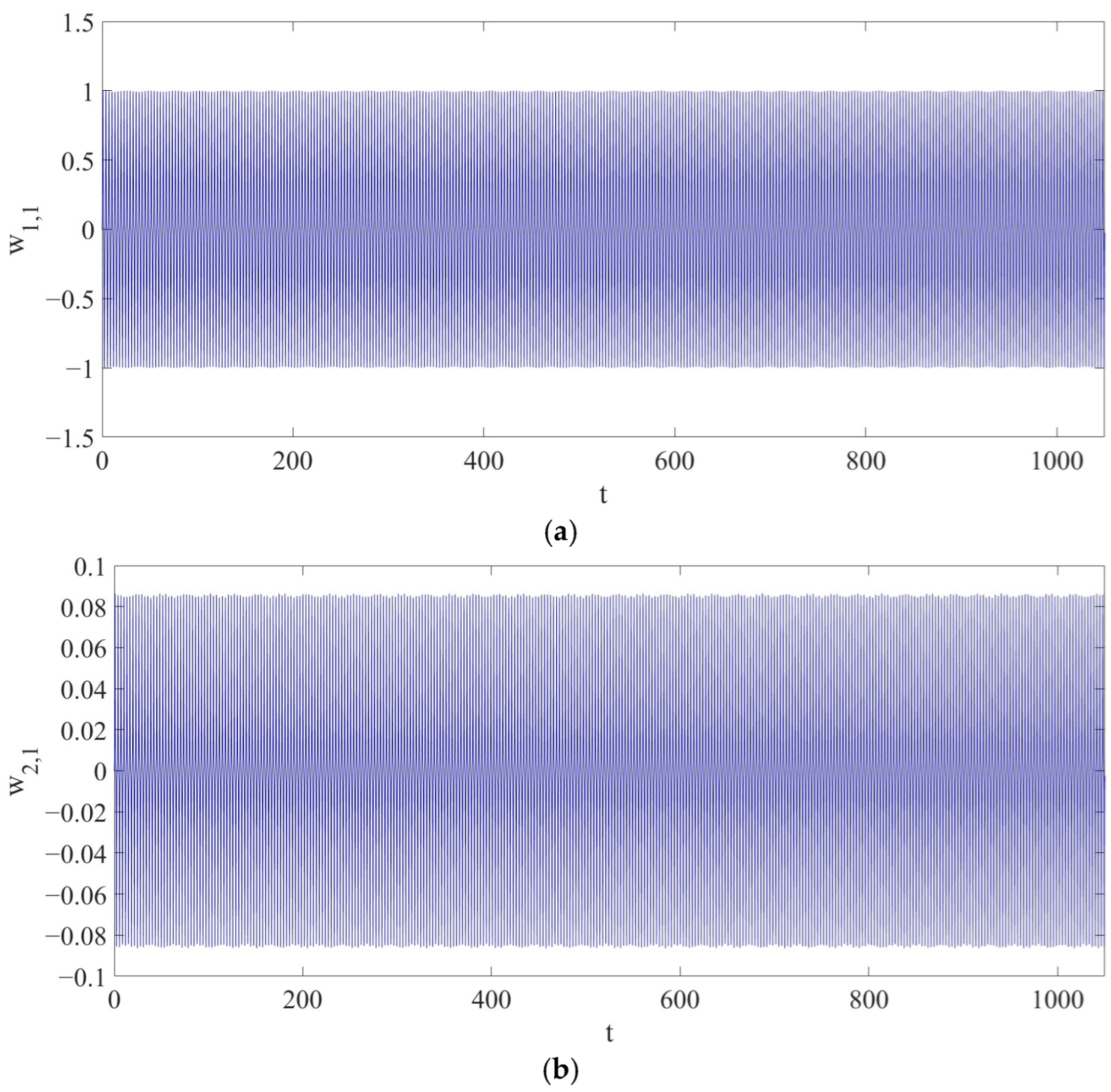
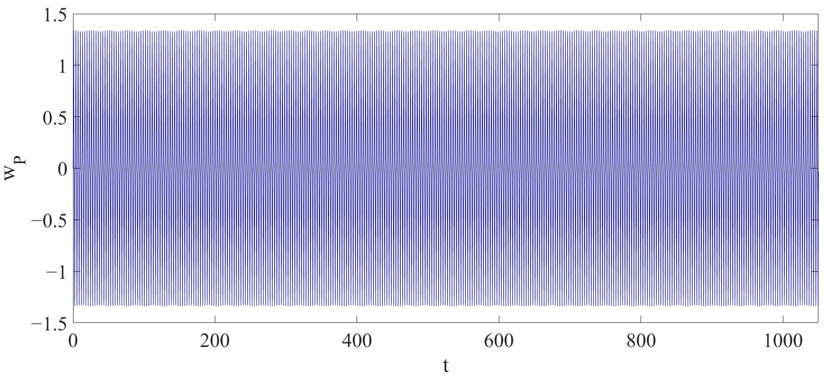
With the parameters of q 0 = 3000 , ω = 20 π , and Γ = 0 % , the LCCB exhibits a periodic vibration as shown in Figure 2, corresponding to a dimensionless time interval of t 0 , 1050 . During this time interval, the maximum amplitude of the periodic vibration w P is approximately 1 . 34 . In Figure 3, the maximum amplitudes of the first vibration mode w 1,1 and the second vibration mode w 2,1 are 1.001 and 0.08637 .
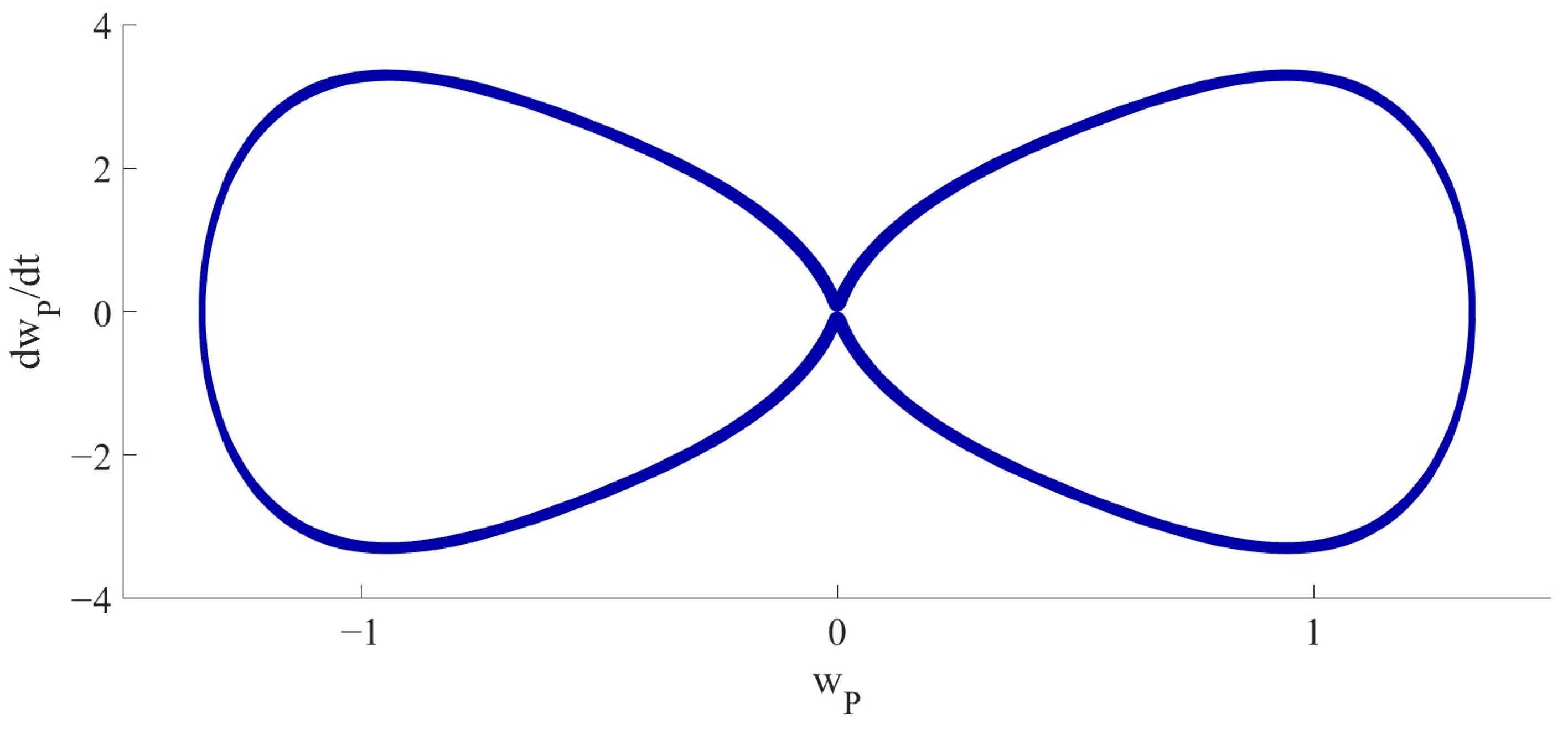
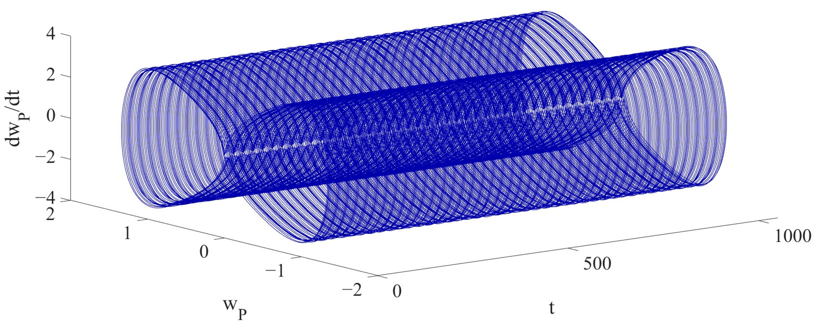
As shown in Figure 4, the 2D phase diagram is presented, with respect to w P and d w P d t , here, d w P d t denotes the nondimensional velocity corresponding to the displacement w P at x P = 0.75 . The plot confirms the periodic vibration of the LCCB. As shown in Figure 5, the 3D phase diagram is presented with respect to w P , d w P d t and t , further demonstrating the periodic vibration. As shown in Figure 4, the non-elliptical closed loop indicates a multi-periodic vibration. For Case 1, the 2D phase portrait is sufficient to demonstrate its periodic characteristics. However, the 3D phase portrait shown in Figure 5 introduces the time dimension, which helps provide a clearer view of the system’s transition from stable periodic vibration to chaotic vibration in the subsequent analysis.
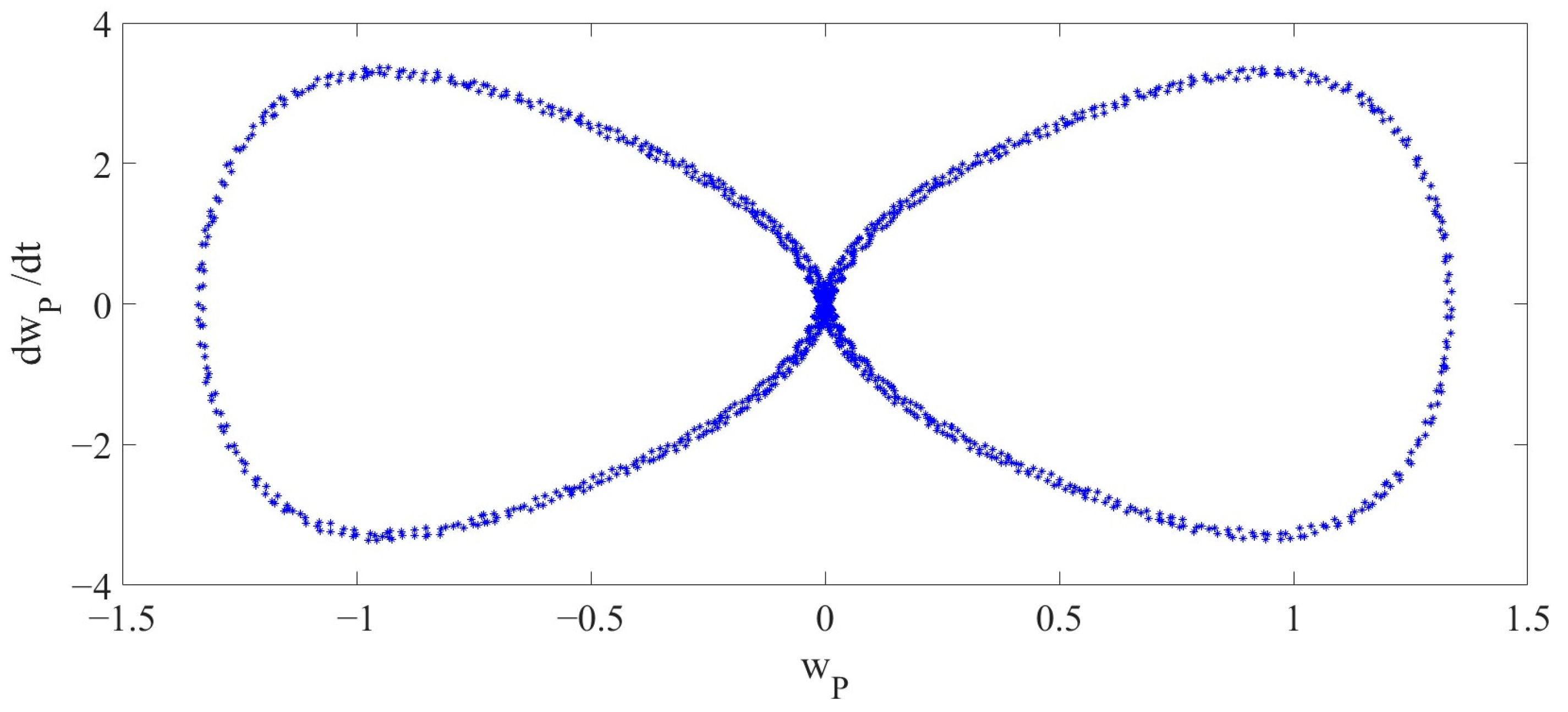
Figure 2, Figure 3, Figure 4 and Figure 5 highlight the stability and regularity of the periodic vibration of the LCCB without RPEs. In addition, Figure 6 also presents the Poincaré map.
In Case 1, no RPE is introduced, and the dynamic behavior of the LCCB remains in a periodic vibration state. Under this condition, the structural response is stable, and no nonlinear instability is observed. In the case of Γ = 0 % , the system exhibits deterministic periodic responses that are consistent with classical nonlinear dynamic characteristics of LCCB, as reported in [38]. This case is treated as a benchmark to assess the influence of increasing RPE levels.

5.2. Case 2

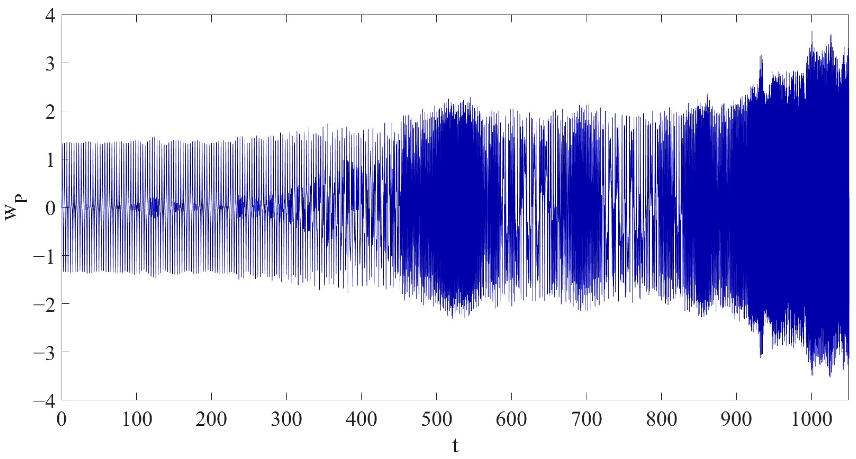
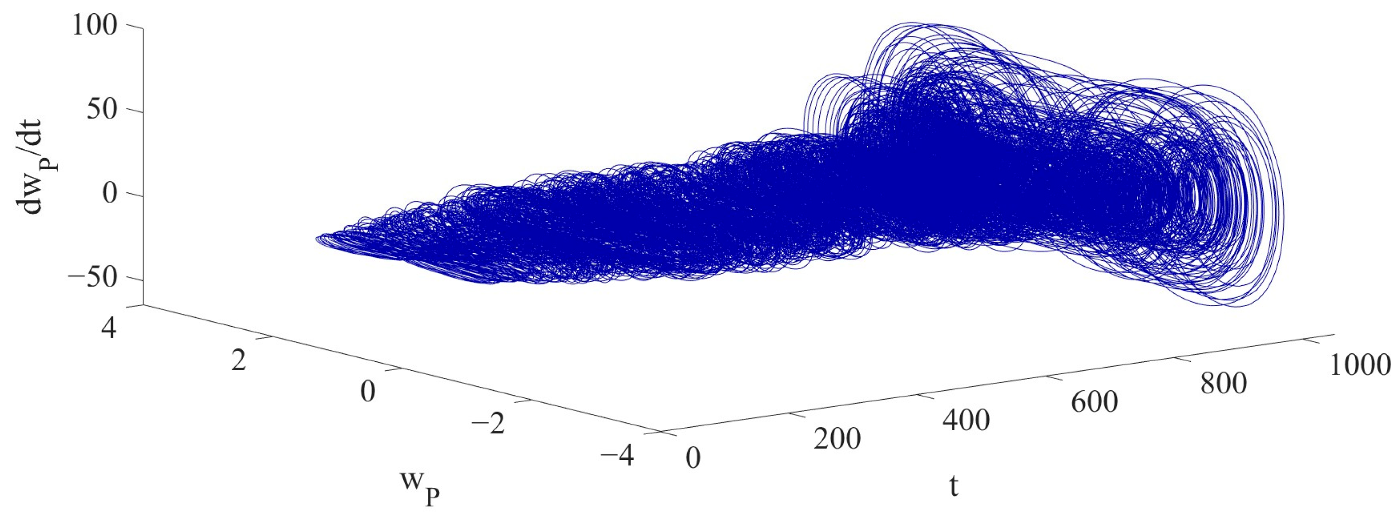
With the parameters of q 0 = 3000 , ω = 20 π , and Γ = 8 % , a chaotic vibration of the LCCB is discovered as shown in Figure 7 in the dimensionless time interval t 0,1050 . That is: compared to the periodic vibration in Case 1, the dynamic behavior of the LCCB exhibits significant changes under the condition of RPEs.
The vibration amplitude of w P gradually increases over time, reaching a maximum value of 3.6636 . Compared to the maximum amplitude in Case 1, the maximum amplitude in Case 2 has increased by approximately 173.4030%. Figure 8 shows the variation in the amplitudes of w 1,1 and w 2,1 , and the maximum amplitudes of w 1,1 and w 2,1 are 2.65201 and 0.654735 . Compared to Case 1, the maximum amplitude of w 1,1 has increased by approximately 164.9361 % , and the maximum amplitude of w 2,1 has increased by approximately 658.0584 % . Therefore, it is demonstrated that the introduction of RPEs has a profound impact on the dynamic behavior of the LCCB.
Compared to Case 1, after introducing an 8% RPE in Case 2, the original periodic vibration of the system loses its stability. The energy transfer between modes is enhanced, and the coupling behavior becomes more complex, leading to a rapid accumulation of nonlinear effects. As a result, the system’s dynamic behavior transitions from periodic to chaotic vibration. In particular, in the primary vibration mode, the excitation of nonlinear terms intensifies the growth of vibration amplitude. This nonlinear coupling mechanism drives the system’s transition from periodic to chaotic vibration.
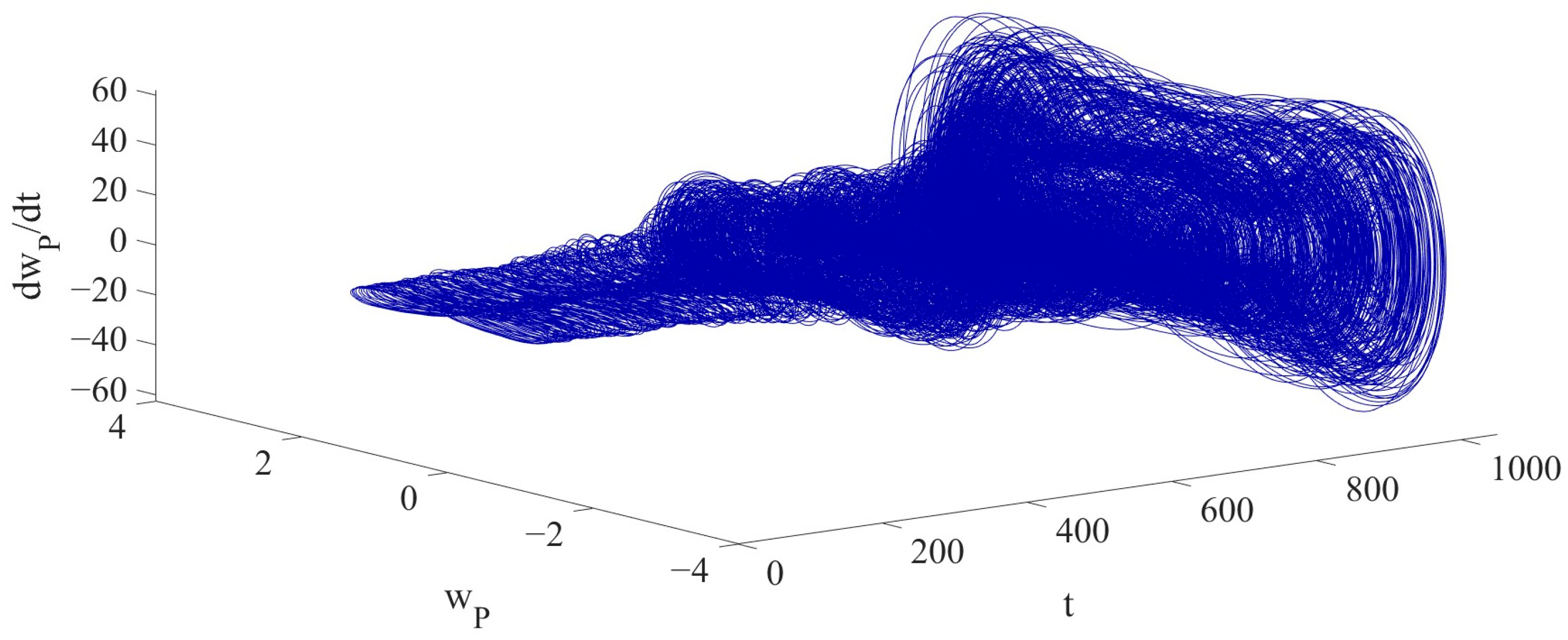
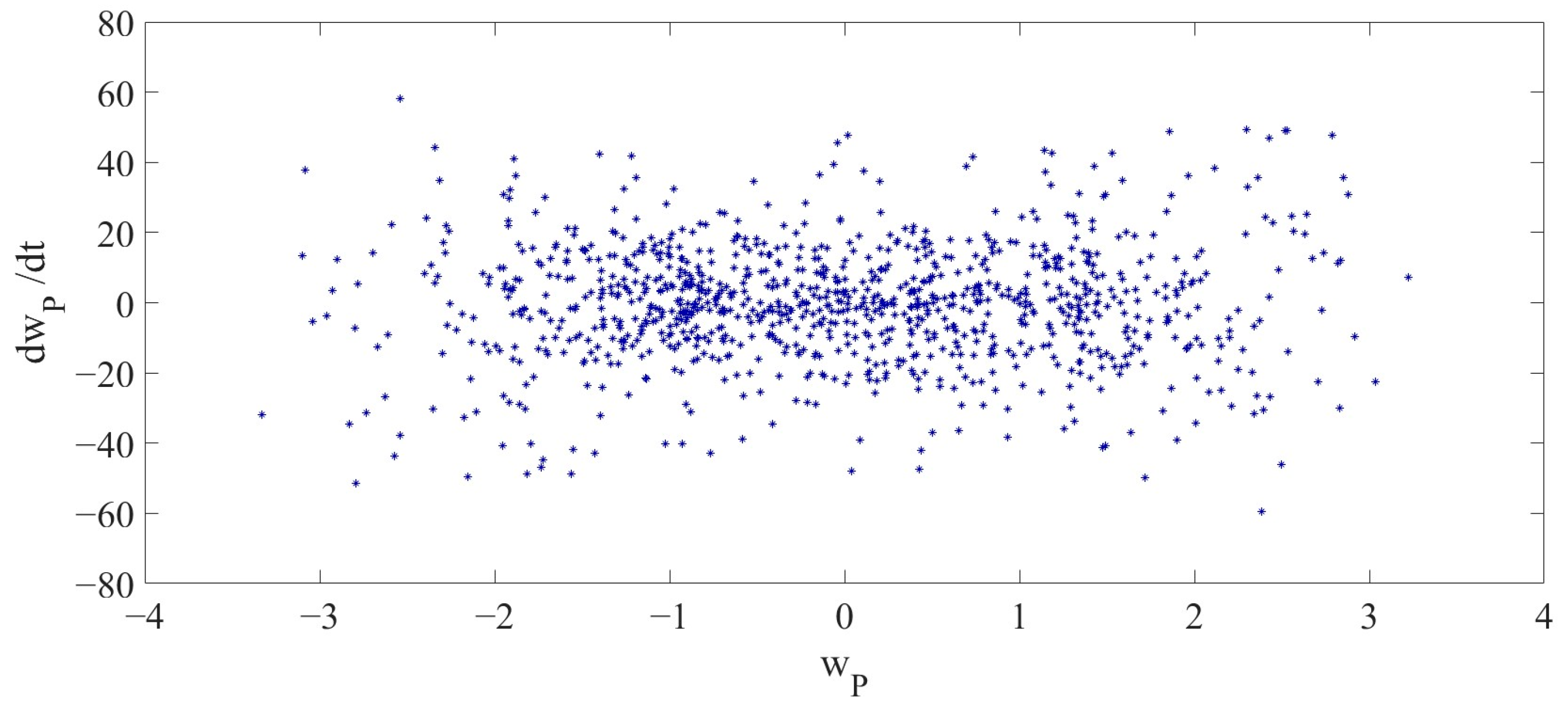
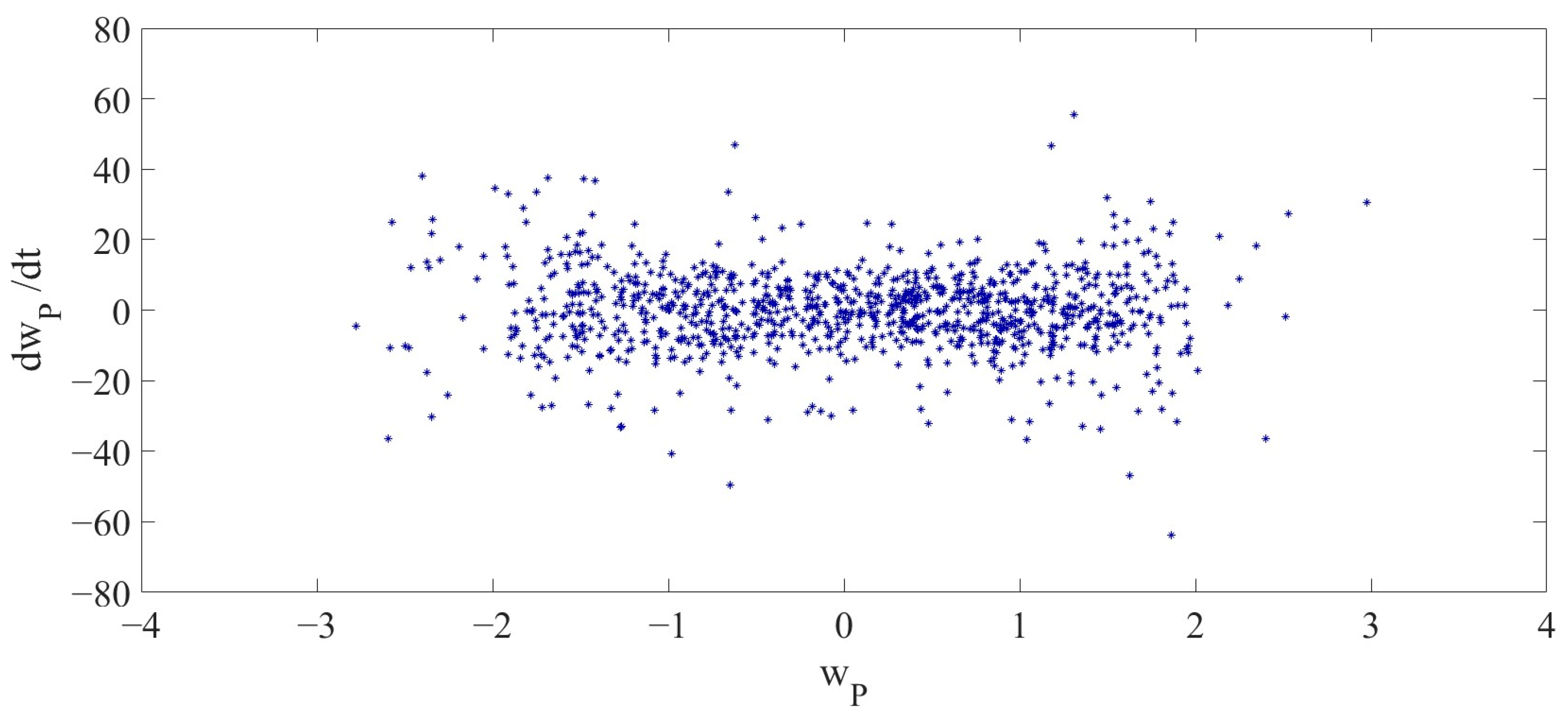
The 2D phase diagram and 3D phase diagram, as shown in Figure 9 and Figure 10, illustrate the vibrations of the LCCB under the influence of RPEs from different perspectives. Compared with the 2D phase diagram and 3D phase diagram in Case 1, it is demonstrated that the vibration of the LCCB changes from the periodic vibration in Case 1 to the chaotic vibration observed in Case 2. The Poincaré map is presented in Figure 11.

5.3. Case 3

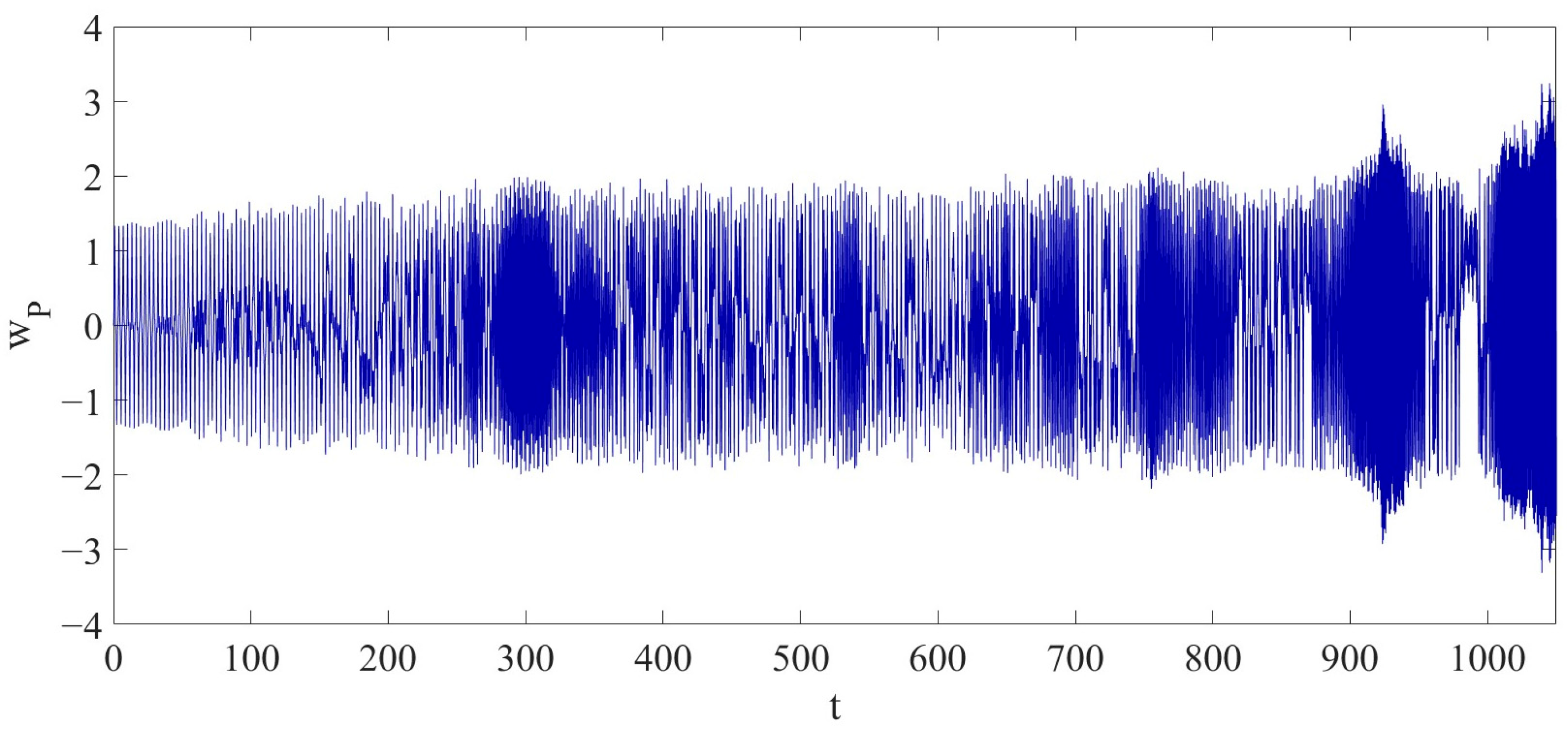
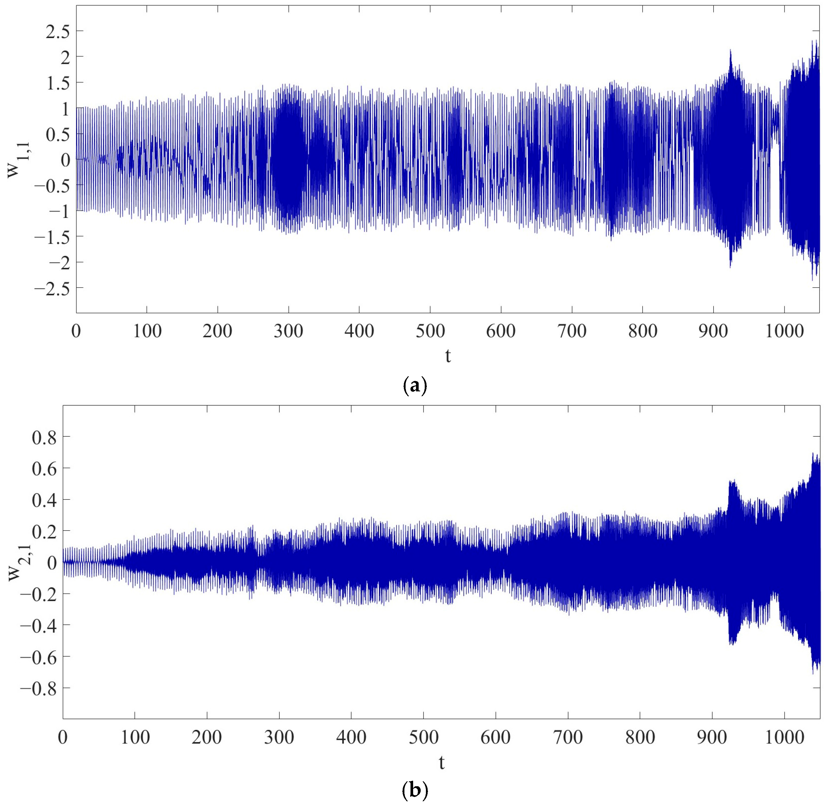
With the parameters of q 0 = 3000 , ω = 20 π , and Γ = 11 % , the LCCB exhibits a chaotic vibration as shown in Figure 12 in the dimensionless time interval t 0 , 1050 . Within this dimensionless time interval, the maximum amplitude of w P is 3.2429 . Compared to the dynamic behavior in Case 2, the maximum amplitude in Case 3 is reduced by 11.4832 % compared to the maximum amplitude in Case 2.
Figure 13 illustrates the variation in the amplitudes of w 1,1 and w 2,1 over the time t . The maximum amplitude of w 1,1 reaches 2.32507 , representing a reduction of approximately 12.3280 % compared to Case 2. Meanwhile, the maximum amplitude of w 2,1 reaches 0.69832 , showing an increase of approximately 6.6569 % compared to Case 2.
It is further demonstrated that the introduction of RPEs also affects the vibration of the LCCB in the case of chaotic vibration as shown in Case 2 and Case 3.
When the RPE increases to 11%, the system remains in a state of chaotic vibration. However, compared to Case 2, the maximum amplitude of the primary vibration mode shows a noticeable decrease. This indicates that as the RPE continues to increase, the nonlinear energy distribution within the system tends to become more dispersed. The energy is no longer highly concentrated in the primary mode but is instead more broadly distributed among other modal components. Although the coupling between modes continues to intensify, this distribution characteristic suppresses further amplitude growth in the primary mode. Under such conditions, the system maintains its chaotic behavior, but the tendency for local energy concentration weakens, reflecting a damping effect of RPE on the primary mode response in nonlinear systems at a certain level.
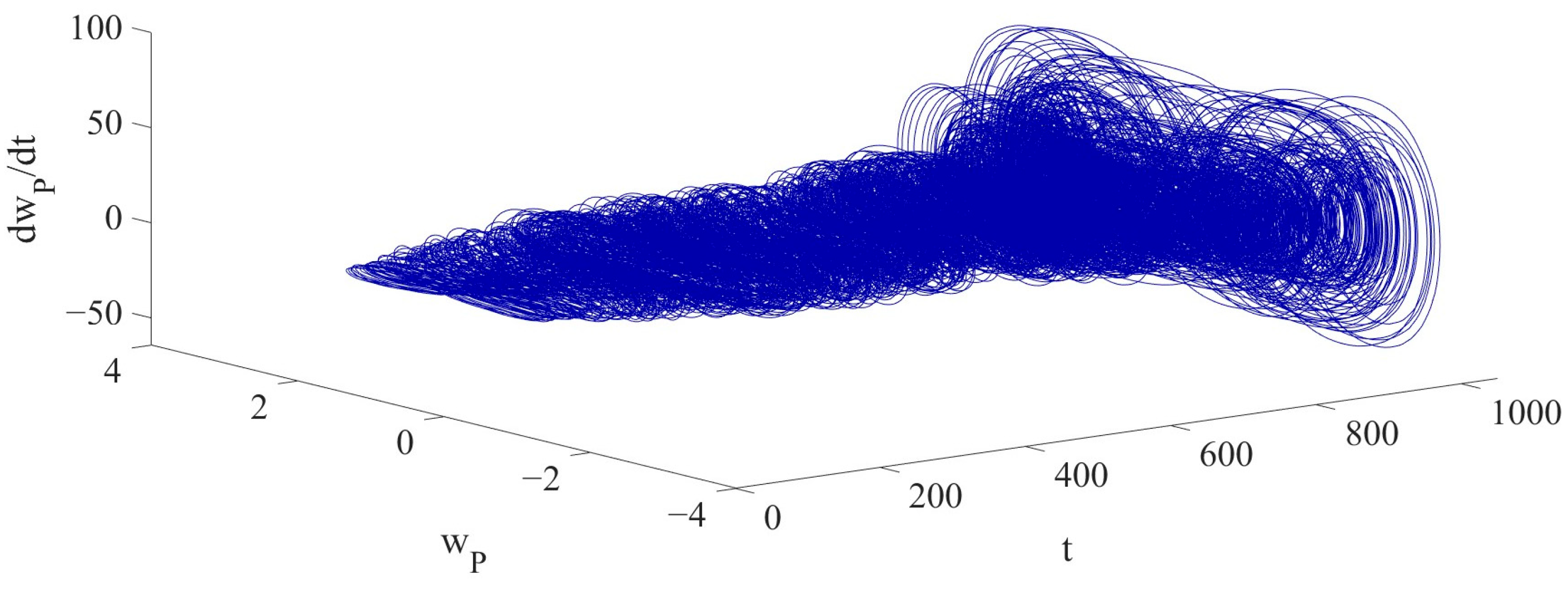
Figure 14 and Figure 15 illustrate the 2D and 3D phase diagrams of the LCCB, showcasing its chaotic vibrations from different perspectives to present the detailed difference in the chaotic vibrations between Case 2 and Case 3. Figure 16 presents the Poincaré map.

5.4. Case 4

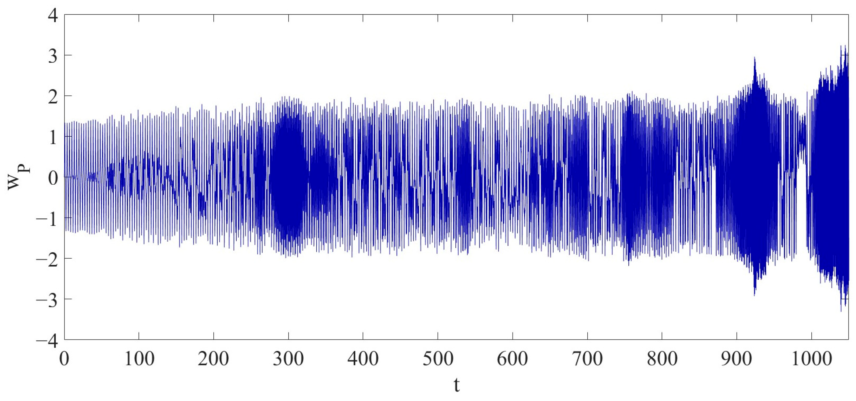
With the parameters of q 0 = 3000 , ω = 20 π , Γ = 15 % , the LCCB exhibits chaotic vibrations as shown in Figure 17 in the dimensionless time interval t 0 , 1050 . During this dimensionless time interval, the maximum amplitude of w P is 3.71562 . It should be noticed that the maximum vibration amplitude in Case 4 has increased by approximately 14.5771 % compared to Case 3. Compared to Case 2, the maximum amplitude of the LCCB in Case 4 does not change significantly, with an increase of approximately 1.42 % .
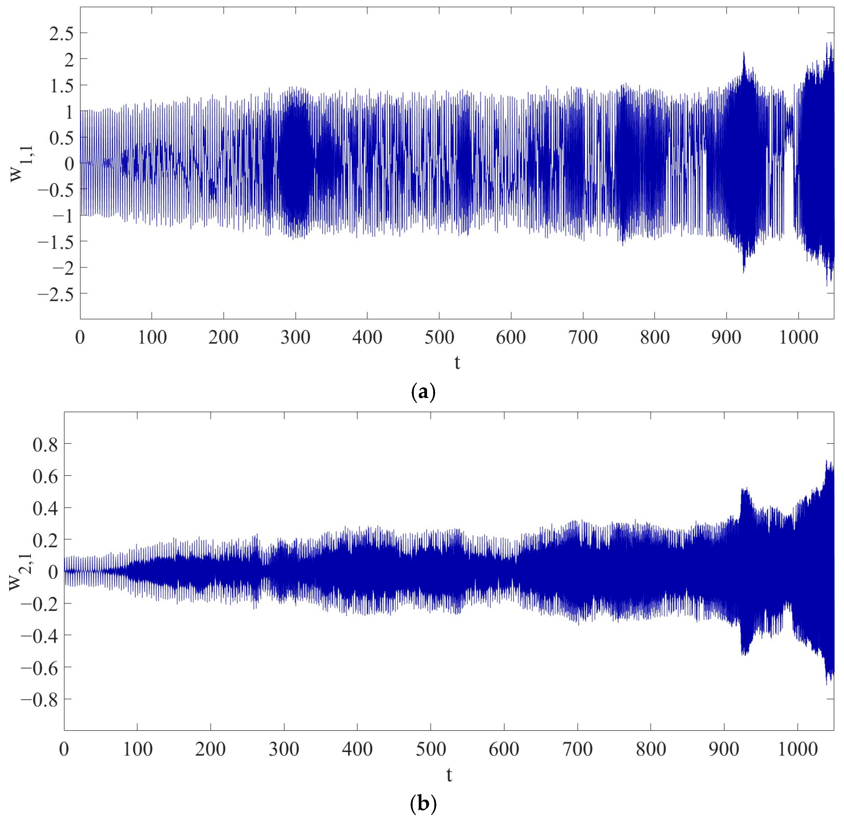
Figure 18 illustrates the variation in the amplitudes of the first vibration mode w 1,1 and the second vibration mode w 2,1 over the time t . The maximum amplitude of w 1,1 reaches 2.7128 , which shows an increase of approximately 16.6761 % compared to Case 3. Meanwhile, the maximum amplitude of w 2,1 reaches 0.667118 , showing a decrease of approximately 4.4682 % compared to Case 3.
When the RPE increases to 15%, the LCCB still remains in a state of chaotic vibration. Compared to Case 3, the maximum amplitude of w P , but it shows no significant change compared to Case 2. This indicates that although a larger RPE can enhance nonlinear coupling and promote the participation of higher-order modes—thus increasing the response of the primary mode to some extent—it also leads to a more dispersed energy distribution within the system. Under the dual effects of enhancement and dispersion, the overall system response tends to reach equilibrium, and the growth of vibration intensity becomes limited. Therefore, when the RPE exceeds a certain level, its amplifying effect on chaotic amplitude gradually weakens and even tends to saturate.
Furthermore, Figure 19 and Figure 20 show the 2D and 3D phase diagrams of the chaotic vibration of the LCCB. The 2D and 3D phase diagrams describe the vibration response of the LCCB under the influence of RPEs from different perspectives, further illustrating its nonlinear dynamic behavior. The Poincaré map is shown in Figure 21.

6. Conclusions

The nonlinear dynamic model of the LCCB established in this study is based on Hamilton’s principle, Reddy’s higher-order shear deformation theory, and the von Kármán nonlinear strain-displacement relationship. On this basis, RPEs are introduced into the system parameters to construct a stochastic time-varying coefficient model related to the uncertainty level Γ . By applying the Galerkin method for modal truncation and discretization, the nonlinear vibration response of the LCCB at x P = 0.75 is investigated. This study reveals that RPEs not only induce changes in the dynamic behavior of the nonlinear LCCB system but also significantly affect the amplitude of its chaotic vibrations. The main conclusions are as follows:
(1)
When Γ increases from 0 % to 8 % , the system response of the LCCB transitions from periodic vibration to chaotic vibration. A comparison between Case 1 and Case 2 shows that the maximum amplitude of the tip displacement w P increases from   1.34 to 3.6636 , representing an increase of approximately 173.40 % . Meanwhile, the maximum amplitudes of the first mode w 1,1 and the second mode w 2,1 increase to 2.65201 and 0.654735 , respectively, corresponding to increases of 164.94 % and 658.06 % compared to Case 1.
(2)
When Γ increases from 8 % to 11 % , the maximum amplitude of w P decreases from 3.6636 to 3.2429 , showing a reduction of approximately 11.48 % compared to Case 2. Meanwhile, the maximum amplitude of w 1,1 decreases by about 12.33%, while that of w 2,1 increases by approximately 6.66 % , indicating that the enhancement of RPE leads to a redistribution of energy among the modes.
(3)
When Γ increases from 11 % to 15 % , the maximum amplitude of w P rises to 3.71562, representing an increase of approximately 14.58 % compared to Case 3. Among the modal components, the maximum amplitude of w 1,1 increases by about 16.68 % , while that of w 2,1 decreases by approximately 4.47 % . Although there is a certain increase compared to Case 3, the amplitude growth in Case 4 is not significant when compared to Case 2, indicating that as RPE continues to increase, its influence on vibration amplitude tends to saturate.
Therefore, RPEs must be considered in design and nonlinear analysis of an LCCB to ensure the stability and reliability of an LCCB structure.

7. Future Development

The present study has demonstrated that RPEs not only influence the dynamic behavior of LCCB but also significantly affect the amplitude of their chaotic vibrations. Nevertheless, several promising directions remain for future research, including the following aspects:
Firstly, future research will include experimental validation of the numerical simulation results. The chaotic behavior observed in experiments will be compared with that in the numerical simulation results, and the reliability of the conclusions will be further enhanced through comparative analysis. In addition, the study will be extended to engineering applications such as vibration control, structural health monitoring, and reliability assessment of composite structures, thereby enhancing the practical value and applicability of the proposed dynamic model in real-world engineering scenarios.
Secondly, to more accurately characterize the dynamic behavior of LCCB, future studies will consider the inclusion of higher-order modes, thereby providing a more comprehensive representation of the system response. At the same time, to enhance the engineering applicability and statistical credibility of the results, repeated simulations will be conducted under multiple samples of random parameter errors. The mean and standard deviation of peak vibration amplitudes will be collected. By introducing such statistical indicators, the nonlinear dynamic characteristics of the structure under the influence of random parameter errors can be revealed in a more systematic manner.

Author Contributions

L.S.: Conceptualization, Methodology, Investigation, Funding Acquisition. X.L. (Xudong Li): Methodology, Writing—Original Draft, Resources. X.L. (Xiaopei Liu): Conceptualization, Methodology, Writing—Review and Editing, Supervision. All authors have read and agreed to the published version of the manuscript.

Funding

This research was funded by the National Natural Science Foundation of China (NNSFC) through grant No. 11602234, as well as the talent scientific research fund of Liaoning Petrochemical University (No. 2017XJJ-058).

Data Availability Statement

The original contributions presented in this study are included in the article. Further inquiries can be directed to the corresponding author.

Conflicts of Interest

The authors declare no conflicts of interest.

Appendix A

T 11 = U 1 S 1 b + U 2 S 2 b ,   T 12 = U 1 S 1 c + U 2 S 2 c ,   T 13 = U 1 S 1 e + U 2 S 2 e T 14 = U 1 S 1 f + U 2 S 2 f ,   T 15 = U 1 S 1 g + U 2 S 2 g ,   T 16 = U 1 S 1 h + U 2 S 2 h T 17 = U 1 S 1 i + U 2 S 2 i ,   T 18 = U 1 S 1 j + U 2 S 2 j ,   T 19 = U 1 S 1 k + U 2 S 2 k T 21 = U 3 S 1 b + U 4 S 2 b ,   T 22 = U 3 S 1 c + U 4 S 2 c ,   T 23 = U 3 S 1 e + U 4 S 2 e T 24 = U 3 S 1 f + U 4 S 2 f ,   T 25 = U 3 S 1 g + U 4 S 2 g ,   T 26 = U 3 S 1 h + U 4 S 2 h T 27 = U 3 S 1 i + U 4 S 2 i ,   T 28 = U 3 S 1 j + U 4 S 2 j ,   T 29 = U 3 S 1 k + U 4 S 2 k U 1 = S 2 d S 1 a S 2 d S 1 d S 2 a ,   U 2 = S 1 d S 1 a S 2 d S 1 d S 2 a ,   U 3 = S 2 a S 1 a S 2 d S 1 d S 2 a ,   U 4 = S 1 a S 1 a S 2 d S 1 d S 2 a S 1 a = 1.000000000 A + 0.8581959666 B 12.35961914 C S 1 b = 1.000000000 D S 1 c = + 2.005226046 E 12.35961914 G + 10.60697530 H S 1 d = 11.74232364 B S 1 e = 0.0000000000 S 1 f = 6.312477510 E 5700.676306 H S 1 g = + 3.994625840 F S 1 h = 67.36709586 F S 1 i = + 201.8072370 F S 1 j = 381.7008418 F S 1 k = + 0.7829242108 S 2 a = + 1.873752475 B S 2 b = 0.0000000000 S 2 c = + 0.5091766256 E + 23.15886696 H S 2 d = 1.000000000 A 13.29402727 B 485.4811154 C S 2 e = 1.000000000 D S 2 f = + 2.018651170 E 485.4811154 G 6453.999206 H S 2 g = + 8.721714324 F S 2 h = 89.63073490 F S 2 i = + 257.8009342 F S 2 j = 432.1411636 F S 2 k = + 0.4339831449 A = I 0 ρ h ,   B = 1 l 2 c 1 I 4 ρ h ,   C = 1 l 4 c 1 J 4 ρ h F 11 c 1 D 11 A 55 6 D 55 c 1 + 9 F 55 c 1 2 ,   D = c ρ h τ ,   F = h A 11 2 ρ τ 2 l 4 ,   G = D 11 ρ h τ 2 l 4 H = c 1 F 11 c 1 H 11 ρ h τ 2 l 6 F 11 c 1 D 11 A 55 6 D 55 c 1 + 9 F 55 c 1 2 A 11 , D 11 , F 11 , H 11 = k = 1 3 z k z k + 1 Q 11 k 1 , z 2 , z 4 , z 6 d z A 55 , D 55 , F 55 = k = 1 3 z k z k + 1 Q 13 k 1 , z 2 , z 4 d z I 0 , I 2 , I 4 , I 6 , = k = 1 3 z k z k + 1 ρ k 1 , z 2 , z 4 , z 6 d z .

References

  1. Zhang, W.; Sun, L.; Yang, X.D.; Jia, P. Nonlinear dynamic behaviors of a deploying-and-retreating wing with varying velocity. J. Sound Vib. 2013, 332, 6785–6797. [Google Scholar] [CrossRef]
  2. Aldaz-Saca, N.H.; Gregori, S.; Gil, J.; Tur, M.; Fuenmayor, F.J. Cantilever modelling in the railway catenary shape-finding problem. Eng. Struct. 2024, 316, 118557. [Google Scholar]
  3. Kormanikova, E.; Kotrasova, K.; Melcer, J.; Valaskova, V. Numerical investigation of the dynamic responses of fibre-reinforced polymer composite bridge beam subjected to moving vehicle. Polymers 2022, 14, 812. [Google Scholar] [CrossRef]
  4. Djojodihardjo, H.; Jafari, M.; Wiriadidjaja, S.; Ahmad, K.A. Active Vibration suppression of an elastic piezoelectric sensor and actuator fitted cantilevered beam configurations as a generic smart composite structure. Compos. Struct. 2015, 132, 848–863. [Google Scholar] [CrossRef]
  5. Filippi, M.; Magliacano, D.; Petrolo, M.; Carrera, E. Variable-kinematics finite elements for propagation analyses of two-dimensional waveguides. AIAA Pap. 2024, 2024–3078. [Google Scholar] [CrossRef]
  6. Filippi, M.; Magliacano, D.; Petrolo, M.; Carrera, E. Wave propagation in prestressed structures with geometric nonlinearities through carrera unified Formulation. AIAA J. 2025, 63, 292–308. [Google Scholar] [CrossRef]
  7. Liu, H.; Qu, Y.; Xie, F.; Meng, G. Vortex-induced vibration of large deformable underwater composite beams based on a nonlinear higher-order shear deformation zig-zag theory. Ocean Eng. 2022, 250, 111000. [Google Scholar]
  8. Zhang, W.; Wang, F.; Yao, M. Global bifurcations and chaotic dynamics in nonlinear nonplanar oscillations of a parametrically excited cantilever beam. Nonlinear Dyn. 2005, 40, 251–279. [Google Scholar] [CrossRef]
  9. Bouadjadja, S.; Tati, A.; Guerira, B. Analytical and experimental investigations on large deflection analysis of composite cantilever beams. Mech. Adv. Mater. Struct. 2020, 29, 118–126. [Google Scholar] [CrossRef]
  10. Fu, Y.; Wang, J.; Hu, S. Analytical solutions of thermal buckling and postbuckling of symmetric laminated composite beams with various boundary conditions. Acta Mech. 2013, 225, 13–19. [Google Scholar] [CrossRef]
  11. Van Viet, N.; Zaki, W.; Umer, R. Bending theory for laminated composite cantilever beams with multiple embedded shape memory alloy layers. J. Intell. Mater. Syst. Struct. 2019, 30, 1549–1568. [Google Scholar] [CrossRef]
  12. Preethi, K.; Raghu, P.; Rajagopal, A.; Reddy, J.N. Nonlocal nonlinear bending and free vibration analysis of a rotating laminated nano cantilever beam. Mech. Adv. Mater. Struct. 2018, 25, 439–450. [Google Scholar]
  13. Zhang, W.; Yang, J.H.; Zhang, Y.F.; Yang, S.W. Nonlinear transverse vibrations of angle-ply laminated composite piezoelectric cantilever plate with four-modes subjected to in-plane and out-of-plane excitations. Eng. Struct. 2019, 198, 109501. [Google Scholar]
  14. Guo, X.; Jiang, P.; Cao, D. Influence of piezoelectric performance on nonlinear dynamic characteristics of MFC shells. Complexity 2019, 2019, 1970248. [Google Scholar] [CrossRef]
  15. Jun, L.; Xiaobin, L.; Hongxing, H. Free vibration analysis of third-order shear deformable composite beams using dynamic stiffness method. Arch. Appl. Mech. 2008, 79, 1083–1098. [Google Scholar] [CrossRef]
  16. Amabili, M.; Ferrari, G.; Ghayesh, M.H.; Hameury, C.; Zamal, H.H. Nonlinear vibrations and viscoelasticity of a self-healing composite cantilever beam: Theory and experiments. Compos. Struct. 2022, 294, 115741. [Google Scholar] [CrossRef]
  17. Zhang, W.; Zhao, M.H.; Guo, X.Y. Nonlinear responses of a symmetric cross-ply composite laminated cantilever rectangular plate under in-plane and moment excitations. Compos. Struct. 2013, 100, 554–565. [Google Scholar]
  18. Guo, X.; Zhang, B.; Cao, D.; Sun, L. Influence of nonlinear terms on dynamical behavior of graphene reinforced laminated composite plates. Appl. Math. Model. 2020, 78, 169–184. [Google Scholar] [CrossRef]
  19. Liu, Y. Nonlinear dynamic analysis of an axially moving composite laminated cantilever beam. J. Vib. Eng. Technol. 2023, 11, 3307–3319. [Google Scholar]
  20. Liu, X.; Sun, L. Chaotic vibration control of a composite cantilever beam. Sci. Rep. 2023, 13, 17946. [Google Scholar] [CrossRef]
  21. Liu, Y.; Ma, W. Nonlinear oscillations of a composite stepped piezoelectric cantilever plate with aerodynamic force and external excitation. Mathematics 2023, 11, 3034. [Google Scholar] [CrossRef]
  22. Sun, L.; Song, Z.; Liu, X. Influence of substrate geometric nonlinearity on the performance of a hybrid galloping energy harvester with D-shape-sectioned bluff body. Sci. Rep. 2025, 15, 23838. [Google Scholar] [CrossRef] [PubMed]
  23. Kuo, C.L. Design of an adaptive fuzzy sliding-mode controller for chaos synchronization. Int. J. Nonlinear Sci. Numer. Simul. 2007, 8, 631–636. [Google Scholar] [CrossRef]
  24. Ablay, G. Sliding mode control of uncertain unified chaotic systems. Nonlinear Anal. Hybrid Syst. 2009, 3, 531–535. [Google Scholar] [CrossRef]
  25. Shirazi, M.J.; Vatankhah, R.; Boroushaki, M.; Salarieh, H.; Alasty, A. Application of particle swarm optimization in chaos synchronization in noisy environment in presence of unknown parameter uncertainty. Commun. Nonlinear Sci. Numer. Simul. 2012, 17, 742–753. [Google Scholar] [CrossRef]
  26. Nozaki, R.; Balthazar, J.M.; Tusset, A.M.; de Pontes, B.R., Jr.; Bueno, A.M. Nonlinear control system applied to atomic force microscope including parametric errors. J. Control Autom. Electr. Syst. 2013, 24, 223–231. [Google Scholar] [CrossRef]
  27. Balthazar, J.M.; Tusset, A.M.; Bueno, A.M. TM-AFM nonlinear motion control with robustness analysis to parametric errors in the control signal determination. J. Theor. Appl. Mech. 2014, 52, 93–106. [Google Scholar]
  28. Peruzzi, N.; Chavarette, F.; Balthazar, J.; Tusset, A.; Perticarrari, A.; Brasil, R. The dynamic behavior of a parametrically excited time-periodic MEMS taking into account parametric errors. J. Vib. Control 2016, 22, 4101–4110. [Google Scholar]
  29. Vahidi-Moghaddam, A.; Rajaei, A.; Vatankhah, R.; Hairi-Yazdi, M.R. Terminal sliding mode control with non-symmetric input saturation for vibration suppression of electrostatically actuated nanobeams in the presence of Casimir force. Appl. Math. Model. 2018, 60, 416–434. [Google Scholar] [CrossRef]
  30. Mahgoub, Y.; El-Badawy, A. Sliding mode control of directly excited structural dynamic model of twin-tailed fighter aircraft. J. Frankl. Inst. 2021, 358, 9721–9740. [Google Scholar] [CrossRef]
  31. Hao, Y.; Gao, M.; Gong, J. Parametric random vibration analysis of an axially moving laminated shape memory alloy beam based on monte carlo simulation. Materials 2022, 15, 562. [Google Scholar] [CrossRef] [PubMed]
  32. Sun, L.; Li, X.D.; Liu, X. Control of large amplitude limit cycle of a multi-dimensional nonlinear dynamic system of a composite cantilever beam. Sci. Rep. 2024, 14, 10771. [Google Scholar] [CrossRef] [PubMed]
  33. Reddy, J.N. Mechanics of Laminated Composite Plates and Shells: Theory and Analysis; Taylor & Francis: Oxfordshire, UK, 2003. [Google Scholar]
  34. Sun, L.; Hou, F.; Liu, X.P. Nonlinear vibration control of a high-dimensional nonlinear dynamic system of an axially-deploying elevator cable. Mathematics 2025, 13, 1289. [Google Scholar] [CrossRef]
  35. Guo, X.Y.; Zhang, Y.M.; Luo, Z.; Cao, D.X. Nonlinear dynamics analysis of a graphene laminated composite plate based on an extended Rayleigh–Ritz method. Thin-Walled Struct. 2023, 186, 110673. [Google Scholar] [CrossRef]
  36. Duo, Y.; Zhang, J.; Wen, X.; Cheng, H.; Liu, H. Free vibration characteristics of CFRP laminate with One-Dimensional periodic structures. Polymers 2023, 15, 1118. [Google Scholar] [CrossRef] [PubMed]
  37. Zhang, B.; Li, Z.; Wu, H.; Nie, J. Research on damping performance and strength of the composite laminate. Sci. Rep. 2021, 11, 18281. [Google Scholar] [CrossRef]
  38. Liu, M.; Lv, J.; Wu, L.; Li, Y. Chaotic vibration control of an axially moving string of multidimensional nonlinear dynamic system with an improved FSMC. Sci. Rep. 2024, 14, 26495. [Google Scholar] [CrossRef]
Figure 1. The structure of a three-layered LCCB.
Vibration 08 00057 g001
Figure 2. The periodic vibration of the LCCB at x P = 0.75 .
Vibration 08 00057 g002
Figure 3. The vibrations for the first-mode vibration and the second-mode vibration: (a) w 1,1 ; (b) w 2,1 .
Vibration 08 00057 g003
Figure 4. Two-dimensional phase diagram at x P = 0.75 .
Vibration 08 00057 g004
Figure 5. Three-dimensional phase diagram at x P = 0.75 .
Vibration 08 00057 g005
Figure 6. Poincaré map at x P = 0.75 for Γ = 0 % .
Vibration 08 00057 g006
Figure 7. The chaotic vibration of the LCCB at x P = 0.75 .
Vibration 08 00057 g007
Figure 8. The vibrations for the first-mode vibration and the second-mode vibration: (a) w 1,1 ; (b) w 2,1 .
Vibration 08 00057 g008
Figure 9. Two-dimensional phase diagram at x P = 0.75 .
Vibration 08 00057 g009
Figure 10. Three-dimensional phase diagram at x P = 0.75 .
Vibration 08 00057 g010
Figure 11. Poincaré map at x P = 0.75 for Γ = 8 % .
Vibration 08 00057 g011
Figure 12. The chaotic vibration of the LCCB at x P = 0.75 .
Vibration 08 00057 g012
Figure 13. The vibrations for the first-mode vibration and the second-mode vibration: (a) w 1,1 ; (b) w 2,1 .
Vibration 08 00057 g013
Figure 14. Two-dimensional phase diagram at x P = 0.75 .
Vibration 08 00057 g014
Figure 15. Three-dimensional phase diagram at x P = 0.75 .
Vibration 08 00057 g015
Figure 16. Poincaré map at x P = 0.75 for Γ = 11 % .
Vibration 08 00057 g016
Figure 17. The chaotic vibration of the LCCB at x P = 0.75 .
Vibration 08 00057 g017
Figure 18. The vibrations for the first-mode vibration and the second-mode vibration: (a) w 1,1 ; (b) w 2,1 .
Vibration 08 00057 g018
Figure 19. Two-dimensional phase diagram at x P = 0.75 .
Vibration 08 00057 g019
Figure 20. Three-dimensional phase diagram at x P = 0.75 .
Vibration 08 00057 g020
Figure 21. Poincaré map at x P = 0.75 for Γ = 15 % .
Vibration 08 00057 g021
Table 1. Model parameters used in the simulations.
ParameterSymbolValueUnitParameterSymbolValueUnit
Beam length l 0.5mShear modulus of skin G 12 s 2.31GPa
Beam thickness h 0.01mShear modulus of core G 12 c 4.14GPa
Beam width b 0.02mPoisson’s ratio (skin) v 12 s 0.34
Density of skin ρ s 1460kg/m3Poisson’s ratio (skin) v 12 s 0.34
Density of core ρ c 1800kg/m3Poisson’s ratio (core) v 12 c 0.26
Elastic modulus of skin E 1 s 76GPaDamping coefficient c 0.01
Elastic modulus of core E 1 c 8.28GPaIntegration time step t 0.001
Table 2. Parameters of q 0 .
Cases q 0 ω Γ Dynamic Phenomena
Case 13000 20 π 0%Period
Case 23000 20 π 8%Chaotic
Case 33000 20 π 11%Chaotic
Case 43000 20 π 15%Chaotic
Disclaimer/Publisher’s Note: The statements, opinions and data contained in all publications are solely those of the individual author(s) and contributor(s) and not of MDPI and/or the editor(s). MDPI and/or the editor(s) disclaim responsibility for any injury to people or property resulting from any ideas, methods, instructions or products referred to in the content.