Article

Vibration Characteristics of Carbon Nanotube-Reinforced Sandwich Nanobeams with Hybrid Cellular Core

1
Department of Mechanical Engineering, Faculty of Engineering, Arak University, Arak 38156-88349, Iran
2
Department of Mechanical Engineering, Faculty of Engineering, Bu-Ali Sina University, Hamedan 65178, Iran
3
School of Mechanical and Mechatronic Engineering, University of Technology Sydney, Sydney, NSW 2007, Australia
*
Author to whom correspondence should be addressed.
Vibration 2025, 8(2), 14; https://doi.org/10.3390/vibration8020014
Submission received: 1 February 2025 / Revised: 6 March 2025 / Accepted: 21 March 2025 / Published: 25 March 2025

Abstract

:
This research explores the dynamic characteristics of composite nano-beams with a hybrid cellular structure (HCS) core, composed of two segments with distinct unit cell configurations, and face sheets reinforced with carbon nanotube (CNT) composites. By considering three-layered sandwich beams with aluminum cores of varying unit cell angles, the study explores a broad spectrum of achievable Poisson’s ratios. The top and bottom face sheets incorporate CNTs, distributed either uniformly or in a functionally graded manner. The governing equations are derived using Eringen’s nonlocal elasticity framework and the modified theory of shear deformation, with solutions obtained via the Galerkin method. A detailed parametric analysis is conducted to evaluate the effects of CNT content, arrangement configurations, hybrid core cellular angles, nonlocal parameters, and slenderness ratio (L/h) on the dimensionless natural frequencies of sandwich nanobeams with hybrid cellular cores. A key contribution of this study is the presentation of natural frequencies for nanobeams with hybrid cellular cores and composite face sheets reinforced with functionally graded CNTs, derived from advanced theoretical formulations. These findings offer new insights into design optimization and highlight the potential applications of hybrid cellular sandwich nanobeams in cutting-edge engineering systems.

1. Introduction

Experimental and theoretical studies have demonstrated that carbon nanotubes (CNTs) exhibit exceptional material properties, including high stiffness, superior elasticity, and remarkable tensile strength [1,2,3,4]. Carbon nanotube-reinforced composites, or nanocomposites with a polymer matrix and carbon nanotube fillers, have gained popularity as promising reinforcement materials [5]. In early research studies, nanocomposites were treated as homogeneous materials with uniform CNT distribution across the thickness. To improve the reinforcement performance, later studies assumed that the CNTs were graded functionally along the thickness of the nanocomposite structure, normally known as functionally graded carbon nanotube-reinforced composites (FG-CNTRCs) [6]. Lai et al. [7] proposed a numerical method for analyzing the free vibrational behavior of a composite beam with temperature-dependent FG-CNTRC face sheets and various boundary conditions, utilizing artificial springs and differential quadrature. Garg et al. [8] scrutinized the flexural behavior and free vibrations of FG-CNTR composite beams with a balsa wood core, employing finite element analysis and higher-order zigzag theory. Building on the hyperbolic shear deformation theory, Belarbi et al. [9] evaluated the bending and buckling responses of FG-CNTRC beams, eliminating the need for correction factors typically applied in conventional equivalent single-layer theories. Masoodi et al. [10] studied the dynamic behavior of FG-CNT reinforced curved beams under thermal conditions, considering various CNT distribution patterns. Their findings offer insights into the effects of temperature and CNT patterns on the vibrational response.
In traditional practice, sandwich structures typically feature a robust, low-density core layer bonded with thin, high-strength layers on the top and bottom. Rostami and Salami [11] investigated the nonlinear vibrational behavior of composite beams incorporating face sheets strengthened with graphene platelets (GPLs), utilizing the extended higher-order theory for sandwich panels. Talebi et al. [12] explored the thermal free vibration of composite beams, incorporating piezoelectric sensors and laminates reinforced with carbon nanotubes. Kammoun et al. [13] studied the free vibration of a sandwich nanobeam, considering the impact of the nonlocal parameter (NP) on the natural frequencies and vibration modes. The findings revealed that an increase in the NP affected the deflection shapes and reduced the natural frequencies, demonstrating the dispersive behavior of frequencies in sandwich nanobeams.
Poisson’s ratio, which is the ratio of the lateral strain to the longitudinal strain under tensile stress in the longitudinal direction, characterizes the mechanical behavior of a material [14]. Most materials exhibit a positive Poisson’s ratio, meaning they contract sideways when strained and expand sideways when compressed. Materials with a negative Poisson’s ratio, referred to as auxetics or auxetic materials as described by Evans et al. [15], exhibit the opposite behavior: they widen sideways when strained and narrow when compressed. Auxetic materials have superior physical and mechanical properties and have been widely studied for various applications in recent years. Li et al. [16] examined the nonlinear vibrations of FG sandwich beams with auxetic copper core and metal–ceramic face sheets using micromechanical modeling and FE simulations. Wen et al. [17] examined the band gaps of composite beams with an auxetic core based on the principles of phononic crystal theory. Zeng et al. [18] proposed a theoretical model for the vibration analysis of a piezoelectric composite nanobeam, incorporating flexo-electricity and utilizing a nonlocal strain gradient theory (NSGT) that addresses both nonlocal elastic stress and higher-order strain gradients. Herisanu et al. [19] explored the dynamic characteristics of an FG Euler–Bernoulli nanobeam with simple support implementing the Optimal Auxiliary Functions Method.
The current study presents a theoretical investigation into the vibration of nanocomposite beams, incorporating a hybrid cellular structure (HCS) core sandwiched between composite layers reinforced with carbon nanotubes (CNTRC). The equations of motion for the composite beam are extracted through the modified shear deformation beam theory and Hamilton’s principle. Subsequently, the Galerkin method is employed to solve these equations under clamped–clamped boundary conditions. An auxetic honeycomb core is formed by varying the core cell angle between negative and positive values. The study examines several geometrical parameters, such as the ratio of rib length to cell wall thickness, rib length ratio, core unit cell angle, functionally graded (FG) distribution pattern, carbon nanotube (CNT) volume fraction, nonlocal parameter, and layer thickness ratios. Comparisons with existing literature are provided to validate the proposed formulations and solution methods, ensuring their accuracy and reliability.

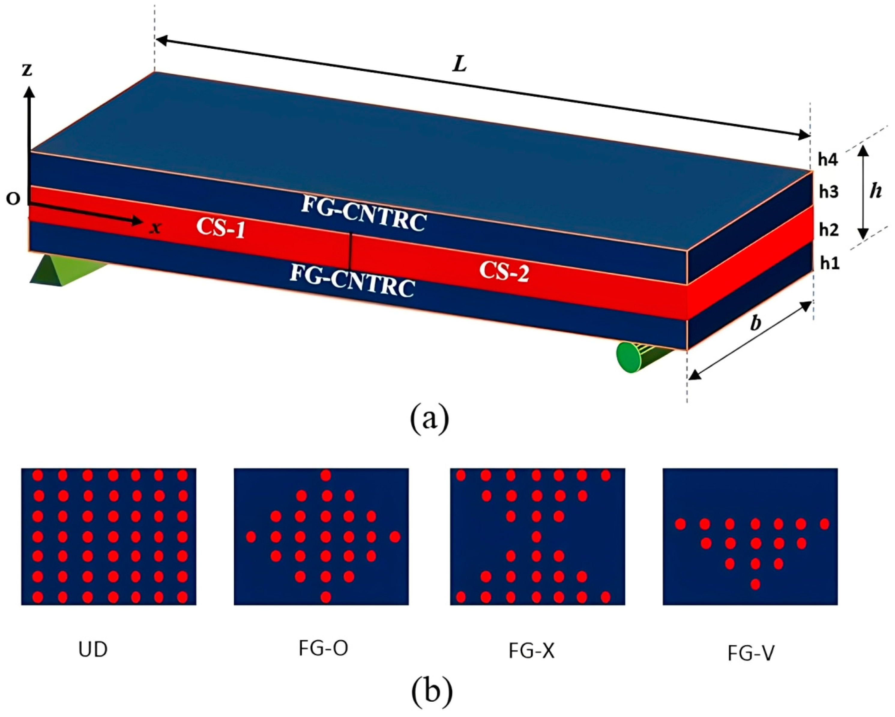
2. Problem Formulation

Figure 1 illustrates a sandwich beam featuring an HCS core and face sheets composed of FG-CNTRCs. The beam’s dimensions, including the span length (L), which denotes the total length between supports, as well as the width (b) and thickness (h), are clearly marked. A Cartesian coordinate system is established with its origin at point O(x, y, z), located at the midpoint of the composite beam’s left end. The FG-CNTRC face sheets are applied to the beam’s bottom and top surfaces, while the core layer is constructed using the hybrid cellular structure. The core of the sandwich beam is a Hybrid Cellular Structure (HCS) composed of two distinct Cellular Structures (CS-1 and CS-2), as labeled in Figure 1. The abbreviation ’CS’ in the figure refers to these individual cellular sections, which together form the hybrid core. This differentiation highlights the structural composition of the core while maintaining consistency with the defined terminology.
In this study, four types of functionally graded carbon nanotube-reinforced composites (FG-CNTRCs) are considered: functionally graded-O (FGO), functionally graded-V (FGV), functionally graded-X (FGX), and uniformly distributed (UD) CNTs as depicted in Figure 1b. The volume fraction distribution of CNTs for various forms of FG-CNTRC beams is expressed as follows [20]:
V c n t = V c n t * U D V c n t * 1 + 2 z h F G V V c n t * 2 4 z h F G O 4 V c n t * z h F G X
V c n t * = w C N T w C N T + ρ C N T / ρ m 1 w C N T
where V C N T , w C N T , ρ C N T , and ρ m denote the volume fraction, mass fraction, the densities of carbon nanotubes (CNTs), and the density of the matrix material, respectively. The volume fraction of CNTs ( V C N T ) plays a crucial role in determining the effective mechanical properties of these nanocomposites. The parameter V c n t *   represents the base volume fraction of carbon nanotubes in the composite material, determined by the mass fraction of CNTs and the density ratio between CNTs and the matrix material. These parameters are central to the material modeling approach, ensuring an accurate representation of the functionally graded properties in the FG-CNTRC face sheets. Various micro-mechanical models have been advanced to envisage the material characteristics of CNT-reinforced nanocomposites. Notable among these are the Eshelby–Mori–Tanaka method and the mixtures rule, which provide effective frameworks for evaluating the mechanical behavior of such advanced materials [21]. In our research, we used the modified rule of mixtures to obtain the effective mechanical and material and mechanical properties of CNTRCs. The conclusive expression for the effective moduli is formulated as follows [22]:
E 11 = η 1 V C N T E 11 C N T + V m E m
E 22 = η 2 V C N T E 22 C N T + V m E m
G 12 = η 3 V C N T G 12 C N T + V m G m
where η i ( i = 1,2 , 3 ) , E, and G indicate the parameters of efficiency, elastic modulus, and shear modulus, respectively. The notation m in subscripts designates the properties associated with the matrix material. Based on the traditional formulation of the rule of mixtures, the additional material characteristics can be defined as follows [23]:
ν 12 = V C N T ν 12 C N T + V m ν m
ρ = V C N T ρ C N T + V m ρ m
V C N T + V m = 1
Figure 2 illustrates the structure of a single unit cell in the HCS core layer, along with the outer skins that enclose the core. In this illustration, Γ1 represents the inclined cell rib’s length, while Γ2 denotes the horizontal rib’s length. The inclination angle is denoted as θ, with the rib thicknesses labeled as t1 for the inclined rib and t2 for the horizontal rib.
The characteristics of the core structure are expressed as follows, with the consideration of parameters ζ 1 = Γ 2 Γ 1 , ζ 2 = t 2 t 1 , and ζ 3 = t 1 Γ 1 [24].
E c = E s ζ 3 3 1 s i n θ co s 3 θ 1 + ta n 2 θ + ζ 1 se c 2 θ ζ 3 2
G c = G s ζ 3 2 cos θ ζ 1 s i n θ 1 + 2 ζ 1 + ζ 1 + 2 s i n 2 θ 2 ζ 1 s i n θ
ν 12 c = s i n θ 1 ζ 3 2 ζ 1 s i n θ co s 2 θ 1 + ta n 2 θ + ζ 1 se c 2 θ ζ 3 2
ν 21 c = s i n θ 1 ζ 3 2 ta n 2 θ + ζ 3 2 ζ 1 s i n θ
ρ c = ρ s ζ 3 ζ 1 + 2 2 cos θ ζ 1 s i n θ
Differences in the unit cell angle give rise to distinct mechanical responses. Figure 3 illustrates the effect of θ on Poisson’s ratio ν21 for different fixed values of ζ1, as indicated in the legend. Each curve represents a specific ζ1 value, ensuring a clear comparison of its influence. Additionally, ζ2 and ζ3 are kept constant in Figure 3, allowing us to isolate the effect of ζ1 on the Poisson’s ratio behavior. The values of ζ1 represent the variation in the core’s geometric properties, with lower ζ1 values resulting in more pronounced changes in Poisson’s ratio, particularly at positive θ, influencing the material’s mechanical response. As θ increases from zero, Poisson’s ratio becomes negative. A reduction in θ results in a rise in Poisson’s ratio, whereas an increase in θ leads to a decrease in Poisson’s ratio.
In Figure 2, a positive cell angle θ leads to a negative Poisson’s ratio for the core layer, a characteristic of auxetic materials. When θ turns negative, the core’s Poisson’s ratio changes to a positive value, classifying the composite as a conventional honeycomb. Additionally, as shown in Figure 3, the Poisson’s ratio of the sandwich beam’s core layer reaches zero when θ is set to 0°.
Strain in the z-direction is neglected due to the beam’s small thickness relative to its length and the assumption of minimal displacement in this axis. Equations (14) and (15) describe the displacement components according to the current beam theory, which incorporates shear deformation effects as follows [25]:
u x x , z = u x g ( z ) w x x + f z φ x
u z x , z = w x
where ux(x,z) and uz(x,z) indicate the x and z components of the displacement vector, with u(x) and w(x) denoting the axial displacement and the transverse displacement, and φ(x) representing the beam’s torsion in the y direction. The function f(z) is a function of z and is defined differently across various beam theories, such as exponential shear deformation theory (ESDBT), trigonometric shear deformation theory (TSDBT), parabolic shear deformation theory (PSDBT), and first-order shear deformation beam theory (FSDBT), as outlined in Table 1.
Equations (16) and (17) define the normal strain and the shear strain in relation to the displacement field as outlined below:
ε x x = u x x g ( z ) 2 w x x 2 + f ( z ) φ x x
γ x z = g z z w x x + f ( z ) z φ x + w x x
The following equations are presented based on the differential form of Eringen’s nonlocal theory [30].
σ x x b , c , t μ 2 2 σ x x b , c , t x 2 = Q 11 ε x x
τ x z b , c , t μ 2 2 τ x z b , c , t x 2 = k s Q 55 γ x z
In this context, the nonlocal parameter μ is defined as e 0 a 2 , where e 0 is a material-dependent constant and a represents the internal characteristic length of the nanostructure. This parameter is derived from Eringen’s nonlocal elasticity theory, which accounts for small-scale effects by incorporating long-range atomic interactions. The value of μ influences the mechanical behavior of nanoscale beams by modifying the stress–strain relationship. Specifically, it establishes a quantitative link between the internal material length scale and the macroscopic dimensions of the structure, ensuring that size-dependent effects are accurately captured in the modeling approach [31]. In these expressions, b, c, and t denote the bottom layer, core layer, and top layer of the beam, respectively. The following expressions describe the outer layers of the composite beam:
Q 11 c = E c 1 ν 12 c ν 21 c
Q 55 c = G c
Q 11 b , t = E 11 b , t 1 ν 12 b , t ν 21 b , t
Q 55 b , t = G 12 b , t
The sandwich nanobeam’s kinetic energy is determined by the following expression:
T = 1 2 V ρ u ˙ x 2 + u ˙ z 2 d V
The definitions for the inertia coefficients are outlined in Equations (25) to (30).
I 1 = h 1 h 2 ρ b d z + h 2 h 3 ρ c d z + h 3 h 4 ρ t d z
I 2 = h 1 h 2 ρ b g z d z + h 2 h 3 ρ c g z d z + h 3 h 4 ρ t g z d z
I 3 = h 1 h 2 ρ b f z d z + h 2 h 3 ρ c f z d z + h 3 h 4 ρ t f z d z
I 4 = h 1 h 2 ρ b g z f z d z + h 2 h 3 ρ c g z f z d z + h 3 h 4 ρ t g z f z d z
I 5 = h 1 h 2 ρ b g z 2 d z + h 2 h 3 ρ c g z 2 d z + h 3 h 4 ρ t g z 2 d z
I 6 = h 1 h 2 ρ b f z 2 d z + h 2 h 3 ρ c f z 2 d z + h 3 h 4 ρ t f z 2 d z
Ultimately, the integral expression for the kinetic energy of the sandwich beam with CNTRC skins is formulated as follows:
δ T = 1 2 A   [ I 1 u ¨ + I 2 w ¨ x I 3 φ ¨ δ u + I 3 u ¨ + I 4 w ¨ x I 6 φ ¨ δ φ I 2 u ¨ x I 5 2 w ¨ x 2 + I 4 φ ¨ x I 1 w ¨ δ w ] d A
The total strain energy is given by the following expression:
U = 1 2 V σ i j ε i j d V = 1 2 V σ x x ε x x + τ x z γ x x d V
The three-layered sandwich beam’s strain energy can be found by replacing Equations (18) and (19) into Equation (33).
U = 1 2 A N x x u x M x x 2 w x 2 + R x x φ x S x z w x + T x z φ + N x z w x d A
where the definitions for Nxx, Nxz, Mxx, Rxx, Sxz, and Txz are as follows:
N x x , N x z = h 1 h 2 σ x x b , τ x z b d z + h 2 h 3 σ x x c , τ x z c d z + h 3 h 4 σ x x t , τ x z t d z
M x x = h 1 h 2 σ x x b g z d z + h 2 h 3 σ x x c g z d z + h 3 h 4 σ x x t g z d z
R x x = h 1 h 2 σ x x b f z d z + h 2 h 3 σ x x c f z d z + h 3 h 4 σ x x t f z d z
S x z = h 1 h 2 τ x z b g z z d z + h 2 h 3 τ x z b g z z d z + h 3 h 4 τ x z b g z z d z
T x z = h 1 h 2 τ x z b f z z d z + h 2 h 3 τ x z b f z z d z + h 3 h 4 τ x z b f z z d z
Finally, the displacement-based integral expression for the sandwich beam’s strain energy can be written as follows:
δ U = 1 2 A δ u N x x x δ w ( 2 M x x x 2 S x z x + N x z x ) δ φ ( R x x x T x z ) d A
By substituting the expressions for kinetic energy and strain energy into Hamilton’s principle [28], as presented in Equation (40), the governing equations for the sandwich HCS nanobeam are derived.
0 t ( δ U δ T ) d t = 0
δ u : N x x x = 1 μ d 2 d x 2 I 1 u ¨ I 2 w ¨ x + I 3 φ ¨
δ w : 2 M x x x 2 S x z x + N x z x = 1 μ d 2 d x 2 I 1 w ¨ + I 2 u ¨ x I 5 2 w ¨ x 2 + I 4 φ ¨ x
δ φ : R x x x T x z = 1 μ d 2 d x 2 I 3 u ¨ I 4 w ¨ x + I 6 φ ¨
Included in Appendix A, the force and moment resultants are presented in terms of displacements. The equations of motion are obtained by replacing the forces and moments in Equations (41)–(43).
δ u : A 1 2 u x 2 A 2 3 w x 3 + A 3 2 φ x 2 = 1 μ d 2 d x 2 I 1 u ¨ I 2 w ¨ x + I 3 φ ¨
δ w : B 1 2 w x x 2 + B 2 φ x x + B 3 2 w x x 2 + A 2 3 u x x 3 C 1 4 w x x 4 + C 2 3 φ x x 3 + E 1 2 w x x 2 E 2 φ x x B 1 2 w x x 2 = 1 μ d 2 d x 2 I 1 w ¨ + I 2 u ¨ x I 5 2 w ¨ x 2 + I 4 φ ¨ x
δ φ : A 3 2 u x x 2 C 2 3 w x x 3 + D 1 2 φ x x 2 + E 2 w x x H 1 φ x B 2 w x x = 1 μ d 2 d x 2 I 3 u ¨ I 4 w ¨ x + I 6 φ ¨
This study uses the Galerkin method to calculate the natural frequency of the sandwich HCS nanobeam with carbon nanotube-reinforced polymer composite skins. Accordingly, the following series of algebraic polynomial functions are assumed [32]:
u ( x , t ) = m = 1 K L x q 0 x p 0 x m 1 u ¯ m e i ω t
w ( x , t ) = n = 1 K L x q 0 x p 0 x n 1 w ¯ n e i ω t
φ ( x , t ) = j = 1 K L x q 0 x p 0 x j 1 φ ¯ j e i ω t
The natural frequency in the provided Equations (47)–(49) is denoted by ω. The values of “p0” and “q0” are both set to 2 in order to meet the fully clamped boundary condition [33]. Subsequently, the calculation of the sandwich beam’s natural frequencies is performed using Equation (50) [34].
  [ K ] ω 2   [ M ] Ψ = 0
where K is the stiffness matrix, M is the mass matrix, and the Ψ signifies the modal shapes.

3. Numerical Results and Discussion

This section analyzes the influence of various parameters on the natural frequency of a three-layered nano-sandwich beam (NSB) composed of hybrid cells and carbon nanotubes. The middle layer of the NSB features a cellular structure, divided into two sections with distinct properties. The mechanical and material characteristics of the beam are directly impacted by the geometrical parameters and the angle in each part of the core structure, leading to variations in the natural frequency values. Furthermore, the upper and lower layers, made of carbon nanotube-reinforced polymer composite, also possess characteristics that directly affect the stiffness of the beam, including the FGV-CNTRC, UD-CNTRC and the V c n t * . The impact of the nonlocal parameter (µ), in conjunction with the aforementioned parameters, has been thoroughly studied and investigated.
The matrix material selected for this study is polymethyl methacrylate, commonly known as PMMA, due to its specific material properties at room temperature (300 K): E m = 2.5   G P a , ρ m = 1190   K g / m 3 , and υ m = 0.3 . Also, in a similar situation, properties of the SWCNTs with ρ c n t = 1400   K g / m 3 , ν 12 c n t = 0.3, G 12 c n t = 1.9445 TPa, E 22 c n t = 7.08 TPa, and E 11 c n t = 5.6466 TPa are chosen [23]. Within this research, single-walled carbon nanotubes (SWCNTs) are considered as reinforcements. The CNTs are assumed to be aligned, straight, and distributed either uniformly (UD-CNTRC) or functionally graded (FG-CNTRC) in the thickness direction of the face sheets. All other relevant CNT parameters are adopted from Reference [35] for consistency. The CNT efficiency parameters [35] with V c n t * = 0.12 are η3 = 0.715, η2 = 1.022, and η1 = 0.137; and with V c n t * = 0.17   are η3 = 1.138, η2 = 1.626, and η1 = 0.142; with V c n t * = 0.28 are η3 = 1.109, η2 = 1.858, and η1 = 0.141. In this study, the physical dimensions (e.g., diameter, length) of CNTs in the face sheets were not directly incorporated into the analysis. Instead, the effective mechanical properties of the FG-CNTRCs were determined using micromechanical models, including the Mori–Tanaka method and the rule of mixtures.
The natural frequencies are analyzed for FGV-CNTRC, UD-CNTRC, and various values of V c n t * (0.12, 0.17, and 0.17). The hybrid cellular structure (HCS) core cell angle ranges from −60 to 60 degrees. The angles of the cells in each HCS section are also represented by θ 1 and θ 2 . Non-local parameters for μ = 0, 1, 2, 3, 4, and 5 are taken into account.
Initially, a comparison and convergence study is performed to check the accuracy of the analysis. The first natural frequency of a beam as listed in Table 2 with the FG-V, UD CNT distribution, V c n t * = 0.28 , and L/h = 25 is obtained and compared with the frequency reported in reference [36], demonstrating strong agreement and accuracy. In order to enable meaningful comparisons, the dimensionless fundamental frequency ( ω ¯ ) is used. This frequency is given by [36] for the specified V c n t * values of 0.12, 0.17, and 0.28.
ω ¯ = ω L ρ m 1 υ m E m
where ρm, νm, and Em are the mechanical characteristics of the matrix material, maintaining homogeneity throughout.
The first-order shear deformation beam theory and higher-order shear deformation theories, utilizing trigonometric, parabolic, and exponential functions, are applied to calculate the natural frequencies of the sandwich beam shown in Figure 4. The frequencies are observed to vary as the cell angles of the first part of the cellular core change from −60 to 60 degrees. A convergence can be observed among the results of the modified shear deformation theories.
In Figure 5, the first and second natural frequencies of the beam are calculated while varying the parameter ζ1 from 0 to 1. Additionally, different carbon nanotube shapes with varying V c n t * are considered. Generally, an increase in ζ1 values reduces the natural frequency values. However, this change has a more noticeable impact on the second natural frequencies. The range of 0.2 to 0.7 has the greatest effect on reducing the frequency values. Furthermore, UD and FVG CNTs with similar V c n t * exhibit different frequency values, with the higher frequency primarily associated with the UD type.
In Figure 6, the impact of variations in the angles of the two parts of the cellular core of the sandwich structure, as well as the changes in the V c n t * , are depicted. The minimum and maximum frequency values correspond to the angles of −60 degrees with UD 0.28 and 60 degrees with UD 0.12, respectively. Additionally, the frequency values for the same UD are more influenced by the change in the θ1 compared to the V c n t * . As observed, the angles of 60 and 0 in the second part of the cellular core have very close values to each other compared to the −60 degree angle.
Figure 7 illustrates how the natural frequencies change in response to variations in the core-to-total beam thickness ratio and the geometric parameters of the cellular core cells. When the core constitutes 10% of the sandwich beam thickness, the geometric parameters of the sheet exhibit negligible influence on the frequency values. The highest and the lowest frequencies are observed at ζ3 = 0.1 and ζ1 = 1, and ζ3 = 0.05 and ζ1 = 1.5, respectively. Conversely, with the core representing 90% of the beam’s thickness, there is a reversal in the positions of the highest and lowest natural frequencies. Another noteworthy discovery arising from this analysis is that beams characterized by different thickness ratios and geometric properties may possess identical natural frequencies. For instance, if the first beam has geometric ratios of ζ3 = 0.1 and ζ1 = 1, and the second beam also has ratios of ζ3 = 0.1 and ζ1 = 1.5, they can both exhibit a natural frequency of approximately 30 at a thickness ratio of 0.2. This frequency equivalence can be explained by the balance between bending stiffness and mass distribution. Although the parameter ζ1 differs between the two cases, the combined effects of ζ1 and ζ3 at this specific core ratio lead to an effective stiffness equivalence, resulting in similar dynamic behavior. This suggests that variations in core geometry do not always produce distinct frequency responses and that certain geometric configurations can counteract each other’s effects on stiffness and mass. Additionally, reducing the thickness of the top and bottom layers relative to the core thickness results in the lowest and highest frequency values in beams with identical geometric properties of the cellular core.
Figure 8 shows that increasing the nonlocal parameter µ from 0 to 5 leads to a sharp decrease of approximately 20% in the frequency values. The effect of another influential parameter, the ratio of the length of the first core region to the total length of the sandwich beam, on the natural frequencies has been systematically investigated. Within the interval of 0 to 0.2, there is a discernible direct relationship between the values. However, as the range extends from 0.2 to 0.7, an inverse correlation emerges between the value of this parameter and the frequency values. This trend undergoes a reversal in the span of 0.7 to 1, transitioning into a direct relationship. As a result, an increase in the numerical value of this parameter leads to a corresponding rise in the beam’s natural frequency.

4. Conclusions

This research investigated the dynamic characteristics of composite nano-beams with a hybrid core structure and face sheets composed of functionally graded carbon nanotube-reinforced composite (FG-CNTRC) materials. Using the modified theory of beams, the strains of the beam under clamped–clamped conditions were derived. The governing equations were extracted through Hamilton’s principle and solved using the Galerkin method. The study explored the effects of varying the core cell angle from negative to positive values to create a hybrid cellular core, which significantly influenced the mechanical behavior of the sandwich nanobeams.
A key innovation of this work is the use of a hybrid cellular core composed of two distinct sections, each with unique cellular structures and mechanical properties. This design allows for tailored mechanical responses, enabling the optimization of the sandwich nanobeam’s dynamic characteristics.
The key findings of this study are as follows:
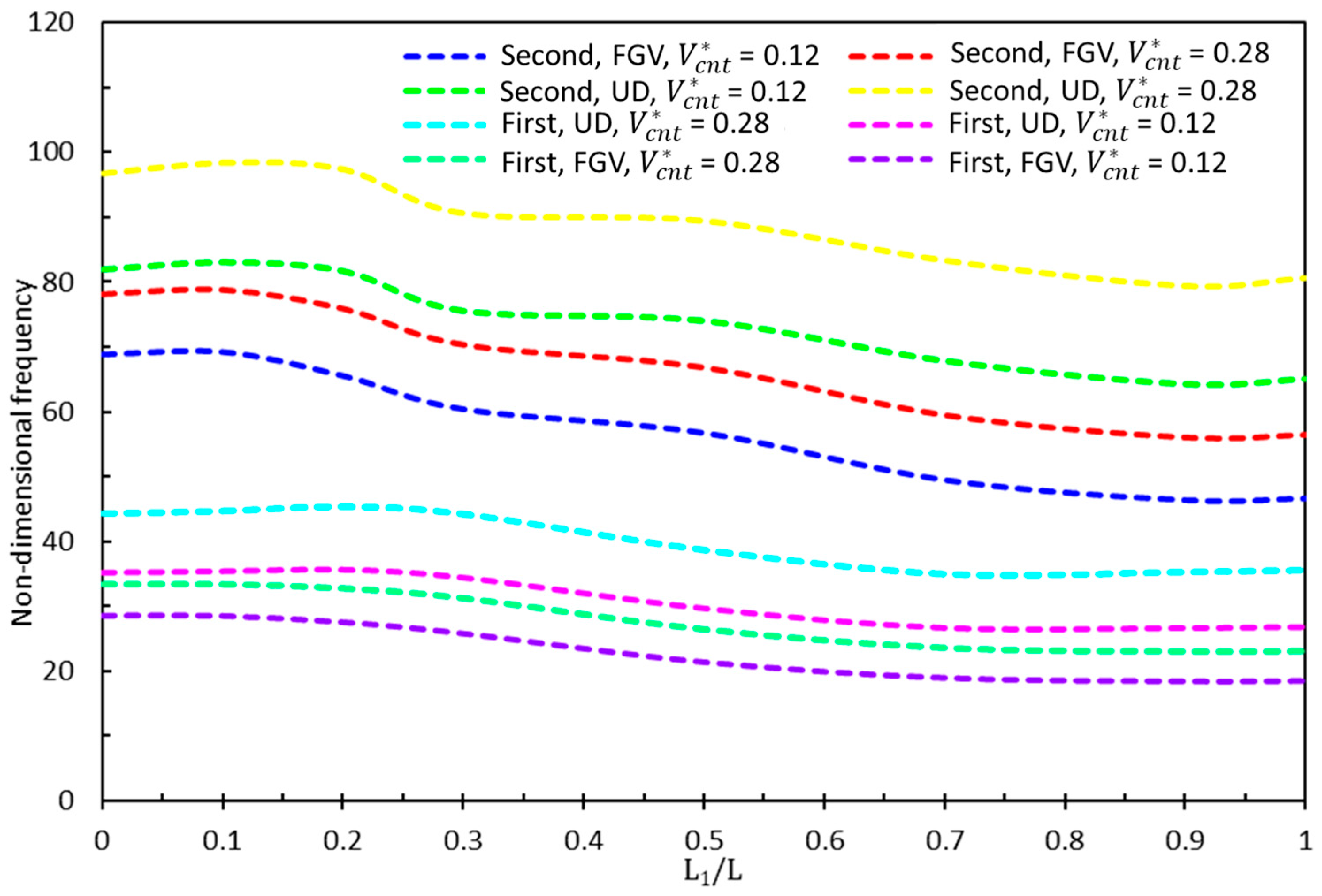
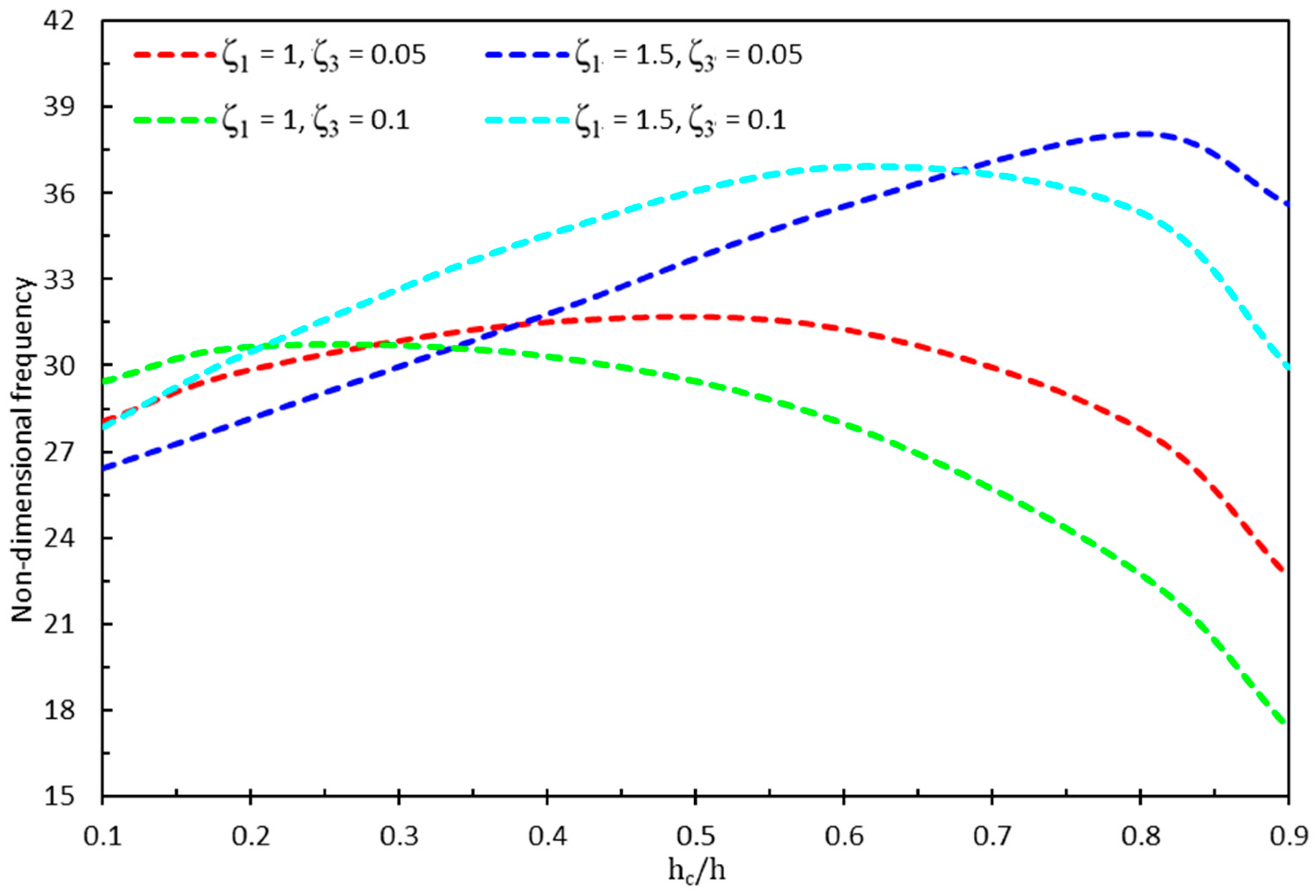
  • Influence of Core Geometry and CNT Distribution: The results revealed an inverse relationship between the frequency values of the sandwich nanobeams and the ζ1 values of the hybrid cellular structure core. Specifically, an increase in ζ1 led to a reduction in natural frequencies, particularly affecting the second natural frequencies more significantly. The study also demonstrated that the flexural stiffness of the beam increased with higher carbon nanotube (CNT) volume fractions, with the functionally graded-V (FGV) distribution showing reduced sensitivity to variations compared to the uniformly distributed (UD) CNT configuration.
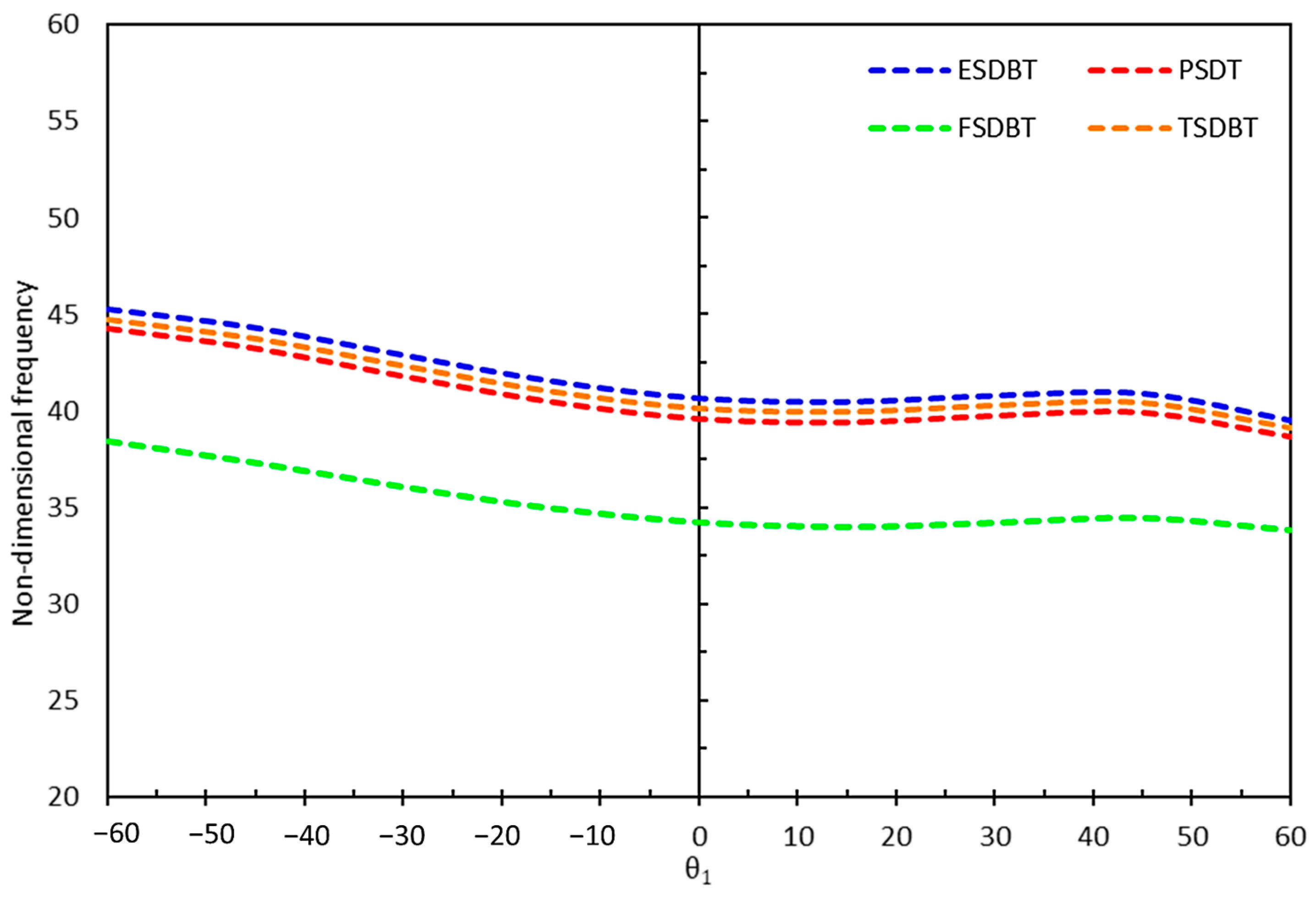
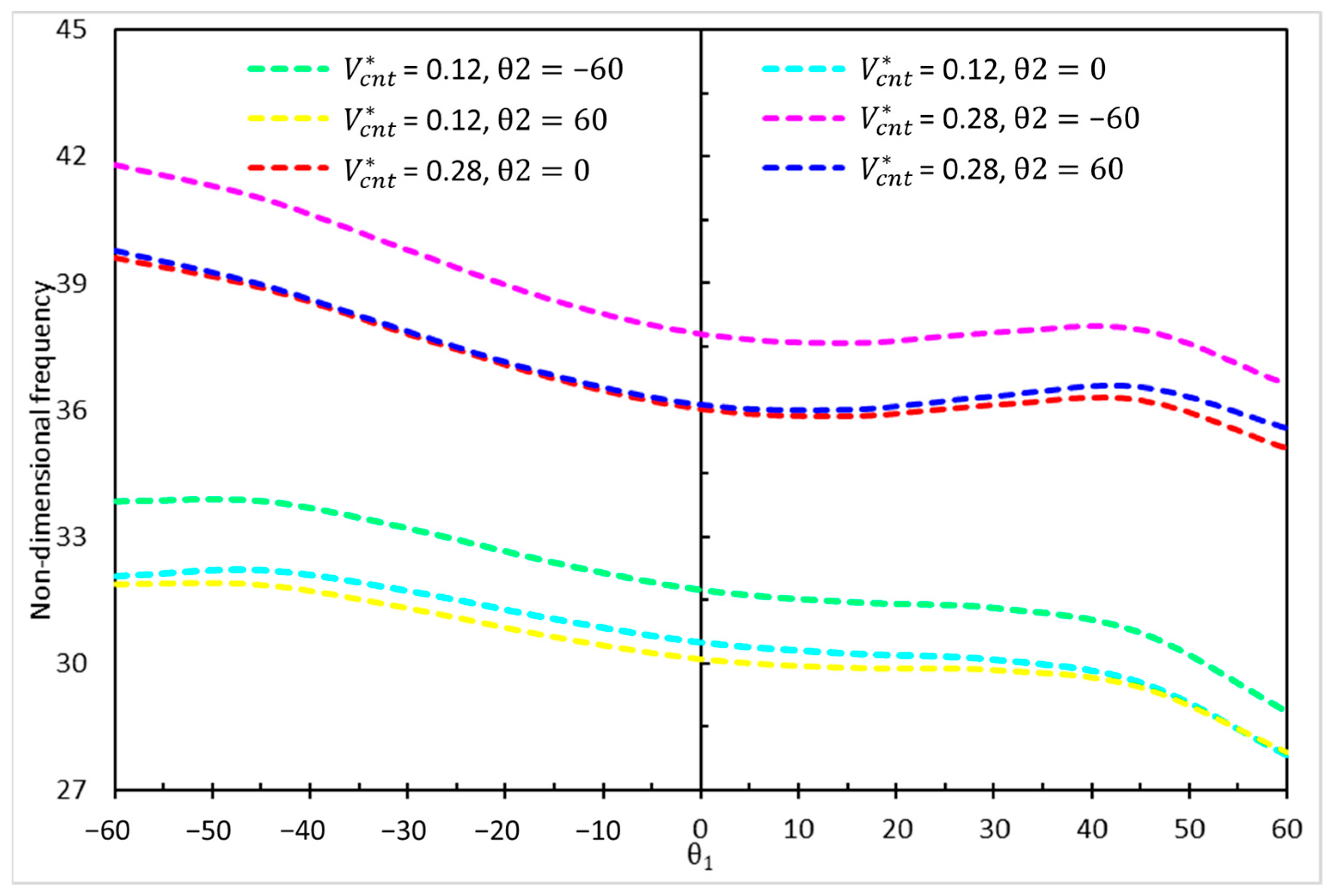
  • Effect of Core Cell Angles: The lowest and highest natural frequencies were observed at core cell angles of −60 degrees with UD 0.28 and 60 degrees with UD 0.12, respectively. The frequency values were more influenced by changes in the core cell angle (θ1) than by variations in the CNT volume fraction. This highlights the importance of core geometry in tailoring the dynamic response of sandwich nanobeams.
  • Thickness Ratios and Geometric Properties: The study revealed that beams with different thickness ratios and geometric properties could exhibit identical natural frequencies. This phenomenon was attributed to the balance between bending stiffness and mass distribution, where certain geometric configurations counteracted each other’s effects. Reducing the thickness of the top and bottom layers relative to the core thickness resulted in the lowest and highest frequency values for beams with identical geometric properties.
  • Nonlocal Parameter (μ): The nonlocal parameter μ had a significant impact on the natural frequencies, with an increase from 0 to 5 leading to a sharp decrease of approximately 20% in frequency values. This underscores the importance of considering size-dependent effects in the design and analysis of nanoscale structures.

5. Potential Future Work

Future research could focus on several key directions. One important avenue is experimental validation, where conducting experimental studies would help confirm the theoretical findings and refine the proposed models. Another aspect to explore is thermal and environmental effects, examining how temperature variations and environmental conditions influence the dynamic behavior of sandwich nanobeams. Additionally, optimization studies could be performed to identify the optimal CNT distribution and core geometry for specific engineering applications. Lastly, multiscale modeling presents an opportunity to develop models that capture the interactions between nanoscale and macroscale behaviors, providing a more comprehensive understanding of these structures.

Author Contributions

Conceptualization, M.J.K.; methodology, P.M. and Y.S.; software, P.M. and Y.S.; validation, M.J.K., P.M. and Y.S.; formal analysis, P.M. and Y.S.; investigation, P.M. and Y.S.; resources, M.J.K., P.M. and Y.S.; data curation, P.M. and Y.S.; writing—original draft preparation, P.M. and Y.S.; writing—review and editing, M.S. and H.K.; visualization, M.J.K., H.K.; supervision, M.J.K.; project administration, M.J.K.; funding acquisition, H.K. All authors have read and agreed to the published version of the manuscript.

Funding

This research received no external funding.

Data Availability Statement

The data presented in this study are contained within the article.

Conflicts of Interest

The author declares no conflicts of interest.

Appendix A

N b , c , t x x = A b , c , t 1 u x x A b , c , t 2 2 w x x 2 + A b , c , t 3 φ x x
N b , c , t x z = B b , c , t 1 w x x + B b , c , t 2 φ x + B b , c , t 3 w x x
M b , c , t x x = A b , c , t 2 u x x C b , c , t 1 2 w x x 2 + C b , c , t 2 φ x x
R b , c , t x x = A b , c , t 3 u x x C b , c , t 2 2 w x x 2 + D b , c , t 1 φ x x
S b , c , t x z = E b , c , t 1 w x x + E b , c , t 2 φ x + B b , c , t 1 w x x
T b , c , t x z = E b , c , t 2 w x x + H b , c , t 1 φ x + B b , c , t 2 w x x
A b , c , t 1 = h 1,2 , 3 h 2,3 , 4 Q 11 b , c , t d z
A b , c , t 2 = h 1,2 , 3 h 2,3 , 4 Q 11 b , c , t g ( z ) d z
A b , c , t 3 = h 1,2 , 3 h 2,3 , 4 Q 11 b , c , t f ( z ) d z
B b , c , t 1 = h 1,2 , 3 h 2,3 , 4 k s Q 55 b , c , t g z z d z
B b , c , t 2 = h 1,2 , 3 h 2,3 , 4 k s Q 55 b , c , t f ( z ) z d z
B b , c , t 3 = h 1,2 , 3 h 2,3 , 4 k s Q 55 b , c , t d z
C b , c , t 1 = h 1,2 , 3 h 2,3 , 4 Q 11 b , c , t g 2 ( z ) d z
C b , c , t 2 = h 1,2 , 3 h 2,3 , 4 Q 11 b , c , t g ( z ) f ( z ) d z
D b , c , t 1 = h 1,2 , 3 h 2,3 , 4 Q 11 b , c , t f 2 ( z ) d z
E b , c , t 1 = h 1,2 , 3 h 2,3 , 4 k s Q 55 b , c , t 2 g z z 2 d z
E b , c , t 2 = h 1,2 , 3 h 2,3 , 4 k s Q 55 b , c , t g z z f ( z ) z d z
H b , c , t 1 = h 1,2 , 3 h 2,3 , 4 k s Q 55 b , c , t 2 f ( z ) z 2 d z

References

  1. Coleman, J.N.; Khan, U.; Blau, W.J.; Gun’ko, Y.K. Small but strong: A review of the mechanical properties of carbon nanotube–polymer composites. Carbon 2006, 44, 1624–1652. [Google Scholar] [CrossRef]
  2. Ma, P.-C.; Siddiqui, N.A.; Marom, G.; Kim, J.-K. Dispersion and functionalization of carbon nanotubes for polymer-based nanocomposites: A review. Compos. Part A Appl. Sci. Manuf. 2010, 41, 1345–1367. [Google Scholar] [CrossRef]
  3. Maâti, H.; Amadine, O.; Sair, S.; Abouelhrouz, S.; Ouadil, B.; Mahi, H.; Essamlali, Y.; Zahouily, M. Carbon Nanotubes Particles: Processing, Mechanical Properties and Application. In Mechanics of Nanomaterials and Polymer Nanocomposites; Abdellaoui, H., Sanjay, M.R., Siengchin, S., Eds.; Springer Nature: Singapore, 2023; pp. 19–49. [Google Scholar]
  4. Chwał, M. Free Vibrations and Flutter Analysis of Composite Plates Reinforced with Carbon Nanotubes. Appl. Sci. 2025, 15, 1140. [Google Scholar] [CrossRef]
  5. Alhakeem, M.R.H. Carbon Nanotube (CNT) Composites and its Application; A Review. Brill. Res. Artif. Intell. 2022, 2, 134–144. [Google Scholar] [CrossRef]
  6. Pouresmaeeli, S.; Fazelzadeh, S.A. Frequency analysis of doubly curved functionally graded carbon nanotube-reinforced composite panels. Acta Mech. 2016, 227, 2765–2794. [Google Scholar] [CrossRef]
  7. Lai, Z.; Li, Z.; Lin, B.; Tang, H. Free vibration analysis of rotating sandwich beams with FG-CNTRC face sheets in thermal environments with general boundary conditions. Z. Naturforsch. A 2022, 77, 1153–1173. [Google Scholar] [CrossRef]
  8. Garg, A.; Chalak, H.D.; Zenkour, A.M.; Belarbi, M.O.; Sahoo, R. Bending and free vibration analysis of symmetric and unsymmetric functionally graded CNT reinforced sandwich beams containing softcore. Thin-Walled Struct. 2022, 170, 108626. [Google Scholar] [CrossRef]
  9. Belarbi, M.-O.; Salami, S.J.; Garg, A.; Daikh, A.-A.; Houari, M.-S.-A.; Dimitri, R.; Tornabene, F. Mechanical behavior analysis of FG-CNT-reinforced polymer composite beams via a hyperbolic shear deformation theory. Contin. Mech. Thermodyn. 2023, 35, 497–520. [Google Scholar] [CrossRef]
  10. Masoodi, A.R.; Ghandehari, M.A.; Tornabene, F.; Dimitri, R. Natural Frequency Response of FG-CNT Coupled Curved Beams in Thermal Conditions. Appl. Sci. 2024, 14, 687. [Google Scholar] [CrossRef]
  11. Rostami, H.; Jedari Salami, S. Large amplitude free vibration of sandwich beams with flexible core and FG Graphene Platelet Reinforced Composite (FG-GPLRC) face sheets based on extended higher-order sandwich panel theory. Thin-Walled Struct. 2022, 180, 109999. [Google Scholar] [CrossRef]
  12. Talebi, S.; Arvin, H.; Beni, Y.T. Thermal free vibration examination of sandwich piezoelectric agglomerated randomly oriented CNTRC Timoshenko beams regarding pyroelectricity. Eng. Anal. Bound. Elem. 2023, 146, 500–516. [Google Scholar] [CrossRef]
  13. Kammoun, N.; Feki, N.; Bouaziz, S.; Ben Amar, M.; Soula, M.; Haddar, M. Free Vibration of Sandwich Nanobeam. In Advances in Acoustics and Vibration III; Feki, N., Abbes, M.S., Taktak, M., Amine Ben Souf, M., Chaari, F., Haddar, M., Eds.; Springer International Publishing: Cham, Switzerland, 2021; pp. 277–284. [Google Scholar]
  14. Shabani, Y.; Khorshidi, K. Buckling Analysis of Sandwich Structures with Metamaterials Core Integrated by Graphene Nanoplatelets Reinforced Polymer Composite. Mech. Adv. Compos. Struct. 2023, 10, 1–10. [Google Scholar] [CrossRef]
  15. Evans, K.E.; Nkansah, M.A.; Hutchinson, I.J.; Rogers, S.C. Molecular network design. Nature 1991, 353, 124. [Google Scholar] [CrossRef]
  16. Li, C.; Shen, H.-S.; Yang, J. Nonlinear Vibration Behavior of FG Sandwich Beams with Auxetic Porous Copper Core in Thermal Environments. Int. J. Struct. Stab. Dyn. 2023, 23, 2350144. [Google Scholar] [CrossRef]
  17. Wen, J.; Wen, X.; Yu, D. Flexural Vibration Band Gaps in Periodic Sandwich Beams with Auxetic Core. In Proceedings of the ASME 2007 International Design Engineering Technical Conferences and Computers and Information in Engineering Conference, Las Vegas, NV, USA, 4–7 September 2007; pp. 471–475. [Google Scholar]
  18. Zeng, S.; Wang, K.; Wang, B.; Wu, J. Vibration analysis of piezoelectric sandwich nanobeam with flexoelectricity based on nonlocal strain gradient theory. Appl. Math. Mech. 2020, 41, 859–880. [Google Scholar] [CrossRef]
  19. Herisanu, N.; Marinca, B.; Marinca, V. Longitudinal–Transverse Vibration of a Functionally Graded Nanobeam Subjected to Mechanical Impact and Electromagnetic Actuation. Symmetry 2023, 15, 1376. [Google Scholar] [CrossRef]
  20. Wang, Q.; Cui, X.; Qin, B.; Liang, Q. Vibration analysis of the functionally graded carbon nanotube reinforced composite shallow shells with arbitrary boundary conditions. Compos. Struct. 2017, 182, 364–379. [Google Scholar] [CrossRef]
  21. Emdadi, M.; Mohammadimehr, M.; Navi, B. Free vibration of an annular sandwich plate with CNTRC facesheets and FG porous cores using Ritz method. Adv. Nano Res. 2019, 7, 109–123. [Google Scholar] [CrossRef]
  22. Shabani, Y.; Khorshidi, K. Free vibration analysis of rectangular doubly curved auxetic-core sandwich panels integrated with CNT-reinforced composite layers using Galerkin method. J. Sci. Technol. Compos. 2022, 8, 1677–1686. [Google Scholar] [CrossRef]
  23. Shen, H.-S. Nonlinear bending of functionally graded carbon nanotube-reinforced composite plates in thermal environments. Compos. Struct. 2009, 91, 9–19. [Google Scholar] [CrossRef]
  24. Zhu, X.; Zhang, J.; Zhang, W.; Chen, J. Vibration frequencies and energies of an auxetic honeycomb sandwich plate. Mech. Adv. Mater. Struct. 2019, 26, 1951–1957. [Google Scholar] [CrossRef]
  25. Ntaflos, K.; Beltsios, K.; Hadjigeorgiou, E. A Unified Shear Deformation Theory for Piezoelectric Beams with Geometric Nonlinearities-Analytical Modelling and Bending Analysis. J. Compos. Sci. 2024, 8, 24. [Google Scholar] [CrossRef]
  26. Aydogdu, M.; Taskin, V.; Aydogdu, M.; Taskin, V. Free vibration analysis of functionally graded beams with simply supported edges. Mater. Des. 2007, 28, 1651–1656. [Google Scholar] [CrossRef]
  27. Şimşek, M. Fundamental frequency analysis of functionally graded beams by using different higher-order beam theories. Nucl. Eng. Des. 2010, 240, 697–705. [Google Scholar] [CrossRef]
  28. Khorshidi, K.; Shabani, Y. Free vibration analysis of sandwich plates with magnetorheological smart fluid core by Using modified shear deformation theory. J. Sci. Technol. Compos. 2022, 8, 1826–1835. [Google Scholar] [CrossRef]
  29. Karama, M.; Afaq, K.S.; Mistou, S. Mechanical behaviour of laminated composite beam by the new multi-layered laminated composite structures model with transverse shear stress continuity. Int. J. Solids Struct. 2003, 40, 1525–1546. [Google Scholar] [CrossRef]
  30. Karami, B.; Janghorban, M.; Shahsavari, D.; Dimitri, R.; Tornabene, F. Nonlocal Buckling Analysis of Composite Curved Beams Reinforced with Functionally Graded Carbon Nanotubes. Molecules 2019, 24, 2750. [Google Scholar] [CrossRef]
  31. Li, C.; Zhang, N.; Li, S.; Yao, L.Q.; Yan, J.W. Analytical Solutions for Bending of Nanoscaled Bars Based on Eringen’s Nonlocal Differential Law. J. Nanomater. 2019, 2019, 8571792. [Google Scholar] [CrossRef]
  32. Elmeiche, A.; Megueni, A.; Lousdad, A. Free Vibration Analysis of Functionally Graded Nanobeams Based on Different Order Beam Theories Using Ritz Method. Period. Polytech. Mech. Eng. 2016, 60, 209–219. [Google Scholar] [CrossRef]
  33. Mehdianfar, P.; Shabani, Y.; Khorshidi, K. Natural frequency of Sandwich Beam Structures with Two Dimensional Functionally Graded Porous Layers Based on Novel Formulations. Int. J. Eng. 2022, 35, 2092–2101. [Google Scholar] [CrossRef]
  34. Shabani, Y.; Mehdianfar, P.; Khorshidi, K. Static Buckling and Free Vibration Analysis of Bi-Dimensional FG Metal Ceramic Porous Beam. Mech. Adv. Compos. Struct. 2024, 11, 149–158. [Google Scholar] [CrossRef]
  35. Shen, H.-S. Thermal buckling and postbuckling behavior of functionally graded carbon nanotube-reinforced composite cylindrical shells. Compos. Part B Eng. 2012, 43, 1030–1038. [Google Scholar] [CrossRef]
  36. Wu, H.L.; Yang, J.; Kitipornchai, S. Nonlinear vibration of functionally graded carbon nanotube-reinforced composite beams with geometric imperfections. Compos. Part B Eng. 2016, 90, 86–96. [Google Scholar] [CrossRef]
Figure 1. (a) A sandwich beam with a hybrid cellular core and face sheets made of functionally graded carbon nanotube-reinforced composite (FG-CNTRC). (b) Different distribution types of carbon nanotubes (CNTs) in the face sheets.
Vibration 08 00014 g001
Figure 2. Schematic representation of a unit cell in the hybrid cellular structure core, illustrating the geometric parameters.
Vibration 08 00014 g002
Figure 3. The relationship between the Poisson’s ratio and the inclined angle of cells, for various cell aspect ratios ζ1.
Vibration 08 00014 g003
Figure 4. Dimensionless sandwich beam frequencies for different values of θ1 using the first and modified shear deformation beam theories.
Vibration 08 00014 g004
Figure 5. First and second frequencies of the structure with various beam lengths, V c n t * and CNT shapes.
Vibration 08 00014 g005
Figure 6. Non-dimensional frequencies of the structure for various values of θ1, θ2, and V c n t * .
Vibration 08 00014 g006
Figure 7. Non-dimensional frequencies for various core-to-total beam thickness ratios and different values of ζ1 and ζ3.
Vibration 08 00014 g007
Figure 8. Non-dimensional frequencies for various nonlocal parameters µ and the first part of core-to-total beam length (L1/L) ratios.
Vibration 08 00014 g008
Table 1. Beam theory shape functions for various models.
Theoryg(z)f(z)
FSDBT [26]zz
PSDBT [27]z z 1 4 z 2 3 h 2
TSDBT [28]z h π sin π z h
ESDBT [29]z z e 2 z h 2
Table 2. Dimensionless frequency comparison of the FG-CNTRC beam.
FG-CNTRCPresent StudyWu et al. [36]
V c n t * = 0.12 V c n t * = 0.17 V c n t * = 0.28 V c n t * = 0.12 V c n t * = 0.17 V c n t * = 0.28
UD1.10741.37481.59201.07061.33251.5322
FGO0.90141.10421.32280.88211.08341.2911
FGX1.22331.53351.76681.17331.47501.6887
Disclaimer/Publisher’s Note: The statements, opinions and data contained in all publications are solely those of the individual author(s) and contributor(s) and not of MDPI and/or the editor(s). MDPI and/or the editor(s) disclaim responsibility for any injury to people or property resulting from any ideas, methods, instructions or products referred to in the content.

