Article

Effects of In-Wheel Suspension on Whole-Body Vibration and Comfort in Manual Wheelchair Users

by
Ahlad Neti
1,2,
Allison Brunswick
1,2,
Logan Marsalko
1,2,
Chloe Shearer
1,3 and
Alicia Koontz
1,2,3,*
1
Human Engineering Research Laboratories, VA Pittsburgh Healthcare System, 6425 Penn Avenue, Suite 400, Pittsburgh, PA 15206, USA
2
Department of Bioengineering, School of Engineering, University of Pittsburgh, 302 Benedum Hall, 3700 O’Hara Street, Pittsburgh, PA 15260, USA
3
Department of Rehabilitation Science and Technology, School of Health and Rehabilitation Sciences, University of Pittsburgh, 4028 Forbes Tower, Pittsburgh, PA 15260, USA
*
Author to whom correspondence should be addressed.
Vibration 2024, 7(2), 432-452; https://doi.org/10.3390/vibration7020023
Submission received: 29 February 2024 / Revised: 25 April 2024 / Accepted: 29 April 2024 / Published: 30 April 2024

Abstract

:
Frequent and prolonged exposure to high levels of vibration and shock can cause neck and back pain and discomfort for many wheelchair users. Current methods to attenuate the vibration have shown to be ineffective and, in some cases, detrimental to health. Novel in-wheel suspension systems claim to offer a solution by replacing traditional spokes of the rear wheels with dampening elements or springs. The objective of this study was to investigate the effects of in-wheel suspension on reducing vibration and shock and improving comfort in manual wheelchair users. Twenty-four manual wheelchair users were propelled over nine different surfaces using a standard spoked wheel, a Spinergy CLX, and Loopwheels while accelerometry data was collected at the footrest, seat, and backrest. Loopwheels lowered vibrations by 10% at the backrest compared to the standard and CLX wheels (p-value < 0.001) and by 7% at the footrest compared to the CLX (p-value < 0.05). They also reduced shocks by 7% at the backrest compared to the standard wheel and CLX (p-value < 0.001). No significant differences were found in comfort between the wheels. Results indicate that Loopwheels is effective at reducing vibration and shock, but more long-term testing is required to determine effects on health.

1. Introduction

Manual wheelchair users (MWUs) propel themselves in many environments and over a wide variety of surfaces every day, including linoleum, carpet, thresholds, sidewalks, asphalt, gravel, and grass [1,2]. Many of these surfaces have the potential to inflict large amounts of whole-body vibration (WBV) on the MWU. WBV is typically characterized by both low-impact, long-term vibrations and high-impact, short-term shocks (e.g., driving over a gravel road versus hitting a large pothole on a smooth road, respectively). Given the frequent and pervasive nature of these surfaces in the home, natural, and built environments, MWUs are unable to avoid many of these surfaces while participating in their daily activities [1,3,4]. For example, when at an intersection, many MWUs are forced to choose between propelling over the rumble strips on the curb-cuts or performing a curb drop; both cases induce large vibrations and/or shocks. Exposure to high levels of WBV has been linked to several adverse health outcomes including neck and back pain/discomfort and neuromuscular fatigue in several populations, including commercial truck drivers, factory workers, and wheelchair users [1,5,6,7].

1.1. Whole-Body Vibration and Impact on Health

Given the risk of health consequences associated with WBV, the International Standards Organization (ISO) has published several guidelines on levels of vibration exposure and their relationship to health outcomes. Specifically, ISO 2631 defines WBV exposure from a seated position [8,9]. Typically, vibrations and shocks in the vertical direction are investigated to determine effects on health, but ISO 2631 also outlines how to analyze other directions [8,9]. Typically, the acceleration in the vertical direction is analyzed to determine vibration with two values: root mean square (RMS) measures the overall magnitude of vibration exposure, whereas the vibration dose value (VDV) is more representative of shorter duration transient shocks experienced during throughout the day [4,8,9,10]. ISO 2631 has also released documentation on the Health Guidance Caution Zone (HGCZ), a region of vibration intensity that has the potential to cause injury [9,11]. This zone is determined for both the RMS and VDV values under different lengths of exposure time [9,11]. For general purposes, ISO 2631 defines the HGCZ for both RMS and VDV for the 4–8 h period of exposure, as these standards were originally developed for use in occupations where shifts last around this time [1,9]. Researchers across many disciplines utilize the ISO 2631 standards as a framework for analyzing exposure to vibration.
In studies that have investigated vibration exposure among MWUs, it was found that current manual wheelchair frames are not sufficient in reducing WBV [3,12,13]. Using novel materials in the frame, such as carbon, has shown some potential to significantly reduce vibration transmissibility compared to aluminum and titanium frames, but it was not investigated whether this improved health outcomes in MWUs, so caution should be taken before recommending them [14]. One study investigated vibration exposure in MWUs during two weeks of community and home use. The researchers found that all 37 participants experienced RMS and VDV values that were within or exceeded the HGCZ [6]. They also found that MWUs are exposed to unsafe levels of WBV around 8–13 h each day and that wheelchair frames with suspension elements did not attenuate vibration significantly [6].

1.2. Current Methods to Reduce WBV

Current methods to reduce WBV in MWUs include accessories (such as backrests and seat cushions), in-frame, front castor, or in-wheel suspension systems. Previous investigations into the effect of seat cushions and customized backrests have indicated mixed results over different surfaces, with some decreasing and others amplifying the WBV [3]. The effect of these accessories was also found to be highly dependent on material and wear and tear [3]. In-frame suspension systems have shock-absorbing spring coils connected between the seat panel and the axle housing. These springs are designed to compress and expand when exposed to vibration and reduce the amount transmitted to the seat [12,13]. As the springs have a fixed orientation within the frame, they are not optimized to handle vibrations and shocks coming from multiple directions, such as when ascending or descending curbs and door thresholds. Other drawbacks include more moving parts in the frame, which typically leads to more repairs or maintenance required and added weight to the wheelchair, which can increase propulsion forces. Front caster suspension systems include products like the Frog Legs, which consist of a carbon fiber spring lever and polymer dampening element that enable the castor to move vertically when encountering an obstacle and then return to its rest position [12,15]. One study using test dummies and an American National Standards Institute/Rehabilitation Engineering Society of North America (ANSI/RESNA) double drum tester found that wheelchairs with suspension castors have significantly lower peak accelerations than those with the original equipment manufactured caster at both the seat and footrest [12]. Another study utilized a robotic propulsion system to simulate a MWU propelling with and without the suspension casters over more common everyday surfaces (brick, aluminum grates, sidewalk, and smooth tile) [15]. This study found that when using the suspension casters, the peak accelerations at the seat increased by nearly 100% depending on the surface type, while at the footrest, there was an average of a 43% increase in accelerations over all surfaces [15]. Unfortunately, these tests were only conducted with a surrogate for the MWU, which fails to take into account biological factors [12,15,16,17,18]. Additionally, WBV values while using suspension systems are still within or exceed the HGCZ, indicating that further efforts are required to reduce vibration to a safe level [12,13]. Other accessories such as seat cushions and back supports have shown to have some benefit in reducing vibration based on the materials used, but their performance is highly dependent on the person’s posture and how much muscle tension is present [3].

1.3. In-Wheel Suspension

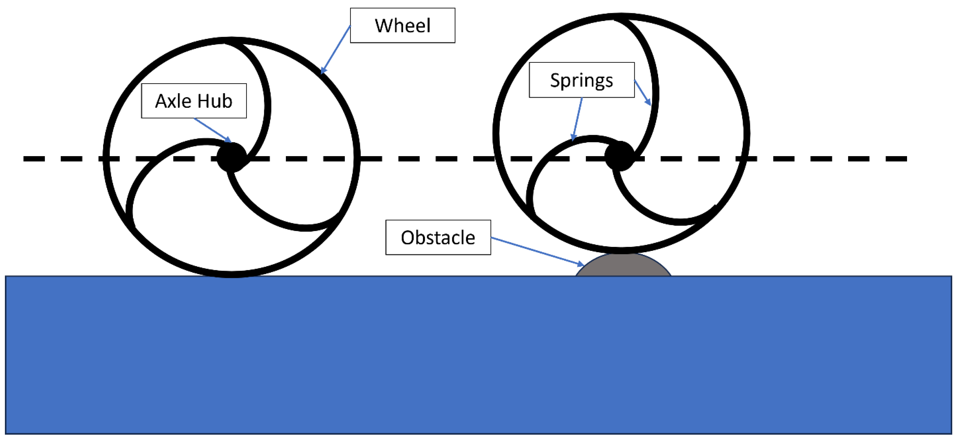
In-wheel suspension systems replace the mags or spokes of the rear wheel with multiple springs that are designed to absorb shock and vibration in all directions as opposed to just one. When the wheelchair encounters an obstacle, the springs allow the axle of the wheel to deflect while keeping the wheel level with respect to the ground (Figure 1). As it is very common for a MWU to perform a wheelie when performing a curb drop or traversing a threshold, the in-wheel suspension systems are more effective than front caster suspension in these scenarios. Additionally, these wheels have a quick-release axle housing, which is common to many wheelchair makes and models, enabling them to be retrofitted to an existing quick-release wheelchair axle frame. There is limited research on how well these systems do at attenuating shock and vibration and improving rider comfort. The Loopwheels Urban (Loopwheels Urban, Jelly Products Ltd., Nottinghamshire, UK), a design encompassing three “C” shaped carbon fiber springs [19], and SoftWheels (SoftWheels, SoftWheels Ltd., Tel Aviv, Isreal), a similar design using gas springs, have been studied along with several other rigid rear wheel types using a robotic wheelchair that simulates MWU propulsion [15]. In this previous investigation, the same surfaces were tested as described earlier for the front caster suspension [15]. Researchers found that Loopwheels increased vibrations by 12–26% at the seat and the footrest; however, SoftWheels showed to be effective at reducing vibrations by 11% over some surfaces at the frame under the seat panel [15]. Another study, focusing specifically on SoftWheels, aimed to investigate rider comfort when using in-wheel suspension [20]. This prior study tested 24 new wheelchair users (recently admitted to a rehabilitation facility) and found that the participants noticed significant improvement when using the suspension wheel over a non-suspension wheel in two specific areas: decreasing the amount of bumps felt and feeling more confident when riding in the chair [20]. Unfortunately, this study failed to test wheelchair users accustomed to propulsion and did not measure the amount of vibration transmitted to the wheelchair. To our knowledge, no vibration-related studies on in-wheel suspension have been conducted with experienced MWUs—for example, those having more time to acclimatize to their disability and with more wheelchair skills experience.

1.4. Study Objectives and Hypothesis

Therefore, the goal of this study was to determine the effects of in-wheel suspension on WBV and ride comfort in experienced MWUs. As certain materials used to construct wheelchair wheels may exhibit dampening properties, we also included a Spinergy CLX (CLX, Spinergy, San Marcos, CA, USA) as another condition in our test protocol, which uses carbon fiber on the rim and Zylon (PBO, poly(p-phenylene-2,6-benzobisoxazole)) spokes [21]. The Loopwheels was also selected for this study as SoftWheels was currently not on the market when this study was conducted.
We hypothesized that the RMS vibration and VDV shock values experienced by the wheelchair frame at the backrest, under the seat panel, and on the footrest would be highest for a pair of standard spoked wheels (Quickie, SouthwestMedical LLC, Phoenix, AZ, USA), followed by the CLX wheels and, lastly, the Loopwheels. We also hypothesized that using the Loopwheels over different surfaces would be most comfortable, followed by the CLX and, lastly, the standard wheels.

2. Materials

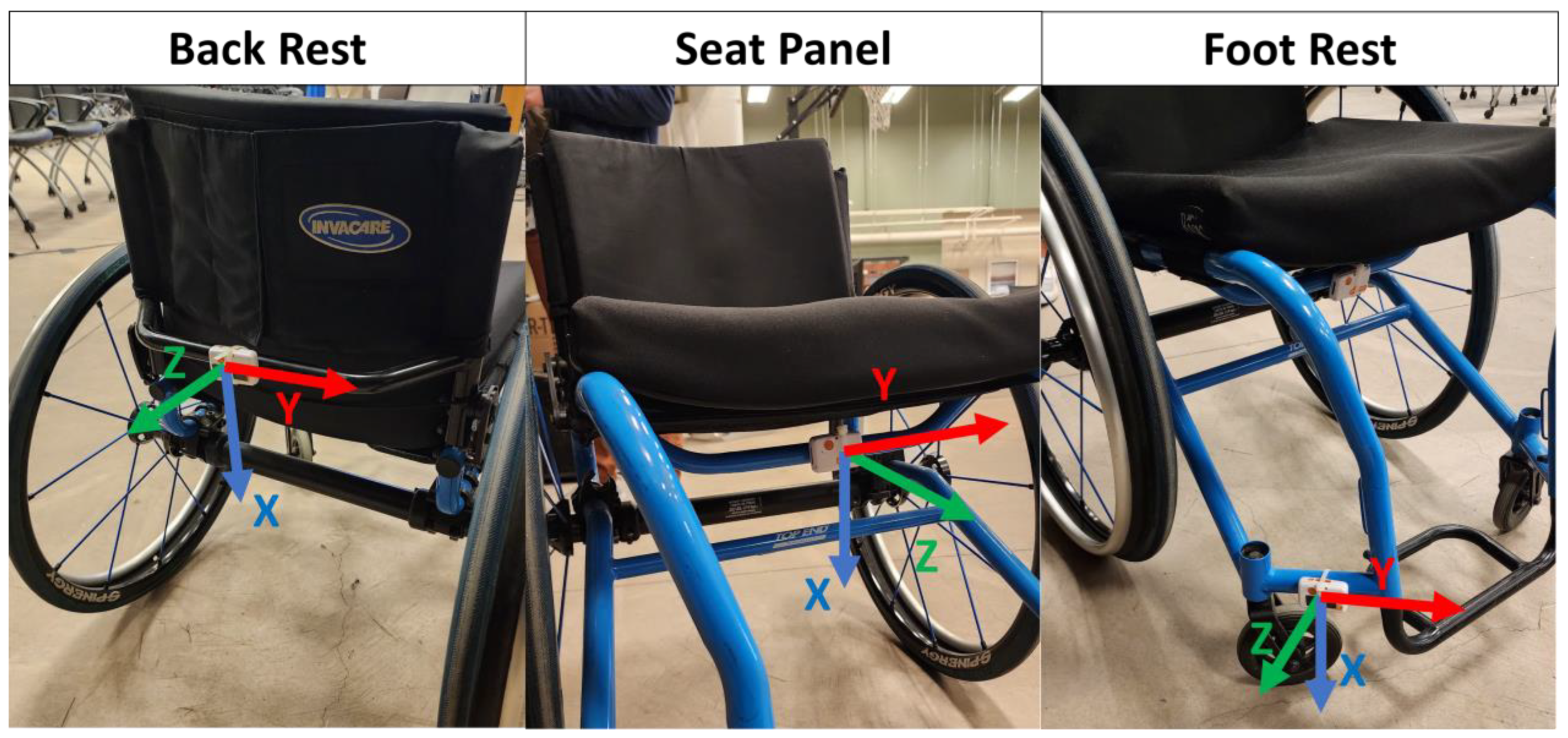
A mobility course composed of nine different surface types designed to simulate a variety of surfaces that MWUs are exposed to was used in this study [2,22,23] (Figure 2). The surfaces and obstacles were set up similar to other studies, using a simulated road course where the surfaces and obstacles were performed in succession instead of in isolation [4]. The mobility course was split into three portions by level of intensity. Factors such as surface roughness, texture, and incline were evaluated when determining which surfaces and obstacles should be in each category. The low-intensity portion contained a high-pile carpet (HPC), low-pile carpet (LPC), and textured rubber mat (RBR). The moderate-intensity portion contained a slat-board with randomly spaced non-uniform gaps (SLT), a small bump (BMP), and a foam wobble board (FBD). The high-intensity portion involved a ramp up (RMP), 4-inch curb drop (CRB), and gravel board (GRV). Three wheel types were tested: standard spoke wheels, Spinergy CLX wheels, and Loopwheels Urban wheels (Figure 3). All wheels were outfitted with standard ½” (1.27 cm)-diameter anodized pushrims and Marathon Plus tires filled to the recommended 125 psi. Furthermore, custom wheel covers were applied to both sides of the wheel to blind the participant to wheel type during testing. Three Shimmer3 IMU (Shimmer3, Shimmer Sensing, Dublin, Ireland) sensors were attached to three points on the participants’ wheelchairs: at the footrest, under the seat panel, and on the backrest. The sensors were attached to parts of the wheelchair frame to control for differences in accessories (such as different seat cushions and backrests). This ensured that the measured vibrations to the frame would be representative of the effect of wheel type. The sensors measured raw acceleration data in three orthogonal axes. Data collection was facilitated wirelessly by a custom Matlab (Matlab 2023a, MathWorks Ltd., Natick, MA, USA) application built from documentation provided by Shimmer. The sensors were secured to the wheelchair frame at these locations with zip-ties to ensure no movement artifact during testing. The accelerometer incorporated a standalone microcontroller (STMicro LSM303AHTR, STMicroelectronics N.V., Geneva, Switzerland) with a 14-bit resolution and high sensitivity (to detect ±8 g) at a sampling frequency of 200 Hz. A diagram of example placements of the sensors and the coordinate system is shown in Figure 4.

3. Methods

3.1. Participant Recruitment

This study was approved by the University of Pittsburgh Internal Review Board (ID: 20020199). Participants were recruited to the study through research registries, local disability community gatherings and events, and word of mouth. The inclusion criteria for participation were (1) be at least 18 years old, (2) have a spinal cord injury diagnosis made at least one year prior to the start of the study, (3) use a manual wheelchair as primary mode of mobility, (4) use 24-inch-diameter wheels with quick-release axle pins, (5) no other suspension elements in frame or castors, (6) weigh under 265 pounds (maximum weight limit of the suspension wheels), (7) self-reported moderate chronic neck and/or back pain, and (8) be proficient in verbal and written English. Individuals were excluded from the study if they had (1) a history of fractures or dislocations in the upper extremity that have not fully recovered, (2) upper limb pain that interferes with propulsion, (3) severe cognitive limitations, or (4) current or recent history of pressure sores.

3.2. Study Protocol

After giving their informed consent, the participant completed a socio-demographic questionnaire and was given their first set of wheels to test. The wheels were retrofit onto the participants’ wheelchair frames via their quick-release axle. Sensors were placed at the three locations on their wheelchair frame: on the backrest, under the seat, and on or near the footrest. The sensor on the backrest was attached to the grab bar or a horizontal piece of the frame on the backrest at the midway point. The sensor under the seat panel was secured to the frame directly under the seat panel and centered under the buttock region to the extent possible. The last sensor was placed on the right side of the frame next to the foot plate or footrest, if applicable. All the sensors were positioned and oriented in a way that the −X axis was the closest to pointing up and the −Z axis was the closest to pointing in the anterior direction. In some circumstances it was not possible to position the sensors at these locations and with the −X axis pointing up due to the variations in wheelchair frame geometry. The sensors were positioned as close to the ideal location as possible provided the given geometry. An example of sensor placement for two different manual wheelchairs is shown in Figure 5. Acceleration data in all three axes was calculated independently according to ISO 2631 and compared to determine the direction of the most vibration exposure. The axis with the largest magnitude of acceleration was used to calculate the WBV for that sensor. In the event of two axes with similar levels of acceleration, ISO 2631 outlines how to combine multiple directions with individual weighting factors.
The order of the wheels was randomized per participant. Before testing began, a random order of the wheels (generated using a random function in Excel v2403) was assigned to each participant ID number. After the test set was placed on each wheelchair, they propelled over the entire mobility course three times, with rest in between trials. They were asked to propel over the course at a self-selected speed consisting of a comfortable and casual pace. Practice runs were used to familiarize themselves with the wheels, the course, and the speed. The participants were also asked to pause for five seconds between each intensity region. Raw acceleration data in three directions was collected by the Shimmer3 sensors at 200 Hz, consistent with the vibration standards [8,9] during the entire trial, and stored in a CSV file for later processing. If the participants finished the course too soon or too fast (e.g., within ±1 s of baseline), the trial was repeated. In between wheel types, the participant completed a study-specific survey modeled after a prior study on ride comfort [24]. The survey asked for the participant’s general comfort going over each of the nine surfaces and obstacles on a 10-cm visual analog scale (VAS), where a higher number indicated greater comfort. A comfort rating was provided for each obstacle independently. Additional questions regarding stability, security, pushrim comfort, maneuverability, and efficiency while using the wheels were also asked, where the answer choices were on a 5-point Likert scale ranging from Not at all (1) to Extremely (5) for each factor evaluated. A copy of this survey can be found in Appendix A.

3.3. Data Processing

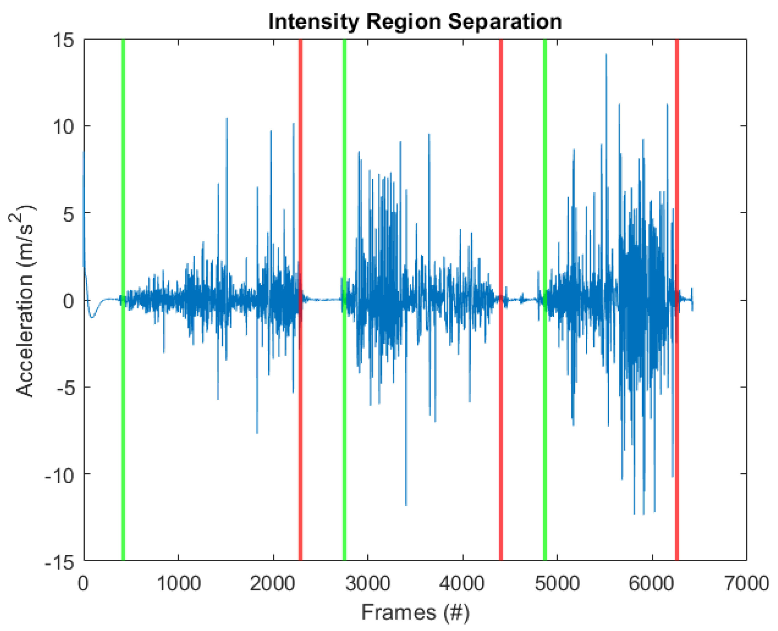
To correct for differences in sensor position and placement between wheelchair frames, each sensor’s coordinate system was rotated so that the z-axis represented the vertical with respect to gravity [8,9]. First, an original coordinate system (O) was established with an identity matrix (Equation (1)). The average accelerations in each axis were used to establish a gravity vector (G), since gravity was the only acceleration present when the participant was not moving (Equation (2)). A new z-axis (Nz) was established using the normalized gravity vector (Equation (3)). Crossing it with the original z-axis (the axis oriented in the anterior–posterior direction) yields the new x-axis (Nx) (Equations (4) and (5)). The last axis, the y-axis (Ny), was calculated by normalizing the cross product of the new z and new x axis (Equations (6) and (7)). Finally, to establish the rotation matrix for the rotation of the sensor to gravity (Rsensor), the new coordinate system was multiplied with the inverse of the original coordinate system (Equation (8)). This rotation matrix was then used to rotate the acceleration data collected during the trial (Equation (9)). Analysis revealed that the acceleration data in the vertical direction (z-axis) had the largest magnitude compared to the other axes in all sensor locations; therefore, all vibration calculations were performed with the new z-axis (Equation (10)). The rotated acceleration values were passed through a 4th order Butterworth bandpass filter of frequencies within 0.4 to 80 Hz (Equation (11)); the values were taken from ISO 2631 [8,9]. Next, a powerband filter was applied to extract the first third octave of frequency domain data, as these are considered to impact whole-body vibration [10] (Equation (11)). The total trial acceleration data was then split into each intensity region manually by visual analysis of the raw acceleration data. Since the participants were asked to start from rest and end with a complete stop, the boundaries could be easily identified. Starting and ending effects from each intensity region were trimmed to avoid the effects of starting and stopping propulsion on vibration. Additional post-processing details for the rotation of sensor coordinate systems to gravity, filtering of raw acceleration data from ISO 2631 guidelines, and separation of the mobility course trial into three intensity regions can be found in Appendix B.
Equations for post-processing acceleration data:
O = 1 0 0 0 1 0 0 0 1
G = a x r a w 2 a y r a w 2 a z r a w 2
N z = G G
N x = O z × N z
N x = N x N x
N y = N z × N x
N y = N y N y
R s e n s o r = N × O 1
A c o r r e c t e d = R s e n s o r × A r a w
A c o r r e c t e d = [ a x c o r r e c t e d , a y c o r r e c t e d , a z c o r r e c t e d ]
a z w e i g h t e d = b a n d p o w e r b a n d p a s s a z c o r r e c t e d

3.4. Vibration Calculations

Two metrics of shock and vibration in accordance with the methods and procedures set by ISO 2631 were computed [8,9]. Root mean square (RMS, Equation (12)) is a validated calculation that represents the vibrations from accelerometer data over a specified period of time (T); on the other hand, vibration dose value (VDV, Equation (13)) is used for describing intermittent or occasional high peak values from accelerometer data [8,9]. Previous studies investigating WBV have included both RMS and VDV values when propelling over a simulated road course [4]. The filtered and weighted accelerometer data were processed through Matlab 2023a using methods derived from ISO 2631 and used to calculate RMS and VDV for each wheel type and for each intensity region. The crest factor was determined to evaluate the validity of the RMS data for the trials. A higher crest factor indicates the presence of low-frequency, high-amplitude shocks, suggesting the VDV values should be analyzed in addition to RMS for describing the WBV [6]. The crest factor is calculated by taking the ratio of the peak filtered acceleration and the RMS value for that trial, and the threshold is given at 9 [8]. If the crest factor is over the threshold for the ISO 2631 analysis, then both the RMS and VDV values should be used for describing WBV. The final filtered, rotated, and frequency-weighted z-axis acceleration was used to calculate the RMS (Equation (12)) and VDV (Equation (13)) for each trial and is oriented in the same direction as gravity, the axis specified by ISO 2631 for vibration analysis. Additionally, the RMS and VDV values were compared against the ISO 2631 HGCZ intervals: RMS: 0.43–0.86 m/s2 and VDV: 8.5–17 m/s1.75 [8]. These intervals are defined for an average vibration exposure time of 4–8 h as these standards were originally designed for occupational use; values below this range have not been clearly investigated in regards to their effect on health [8]. Values of WBV exposure within these intervals should be treated with caution as they have a potential to cause health risks, and values above this region are highly likely to cause health risks [8]. The final RMS and VDV values were averaged over the three trials per wheel type per intensity region.
Equations for calculating WBV from weighted acceleration:
R M S w e i g h t e d = 1 T a z w e i g h t e d 2
V D V w e i g h t e d = a z w e i g h t e d 4 4

3.5. Ride Comfort Survey

The results from the comfort survey were compiled for each wheel type and averaged over all the participants. Comfort for each obstacle was calculated from the VAS by measuring the distance in centimeters from the zero point to the mark indicated by the participant for that specific obstacle. An overall average comfort score across all surfaces was calculated for each participant and wheel type.

3.6. Statistical Tests

All statistical tests were conducted in R Studio 2023.09.0 (RStudio, R-Tools Technology Inc., Boston, MA, USA) [25]. A two-way repeated measures MANOVA was used to investigate the main and interaction effects of wheel type and obstacle intensity on WBV values at each sensor location. Post-hoc tests were performed on specific pair-wise differences between the standard wheels, Loopwheels, and CLX wheels. Another post-hoc on pair-wise differences between intensity regions was also conducted. A one-way repeated measures ANOVA was used to investigate main effects of wheel type on comfort scores by surface type and overall. All the ANOVAs were computed with a 95% confidence level, and a p-value of less than 0.05 indicates significant differences between wheel type.

4. Results

4.1. Participants

A total of 24 MWUs (18 men and 6 women) with spinal cord injuries/disorders participated in this study. The participants were, on average, 41.9 ± 10.6 years old, 170.9 ± 9.2 cm tall, and weighed 83.4 ± 19.1 kg. The participants were, on average, 20 ± 13.5 years (a range of 2.4 to 45.9 years) post-injury.

4.2. Crest Factor Analysis

Crest factors were calculated for each trial, intensity region, and wheel type separately and averaged over the three trials. All calculated crest factors were above 9 (the average crest factor across all participants, trials, and conditions was 15.9), indicating that several low-frequency, high-amplitude shocks were observed. Therefore, both the RMS and VDV values were analyzed to evaluate the WBV.

4.3. RMS and VDV: Effects of Wheel Type and Intensity

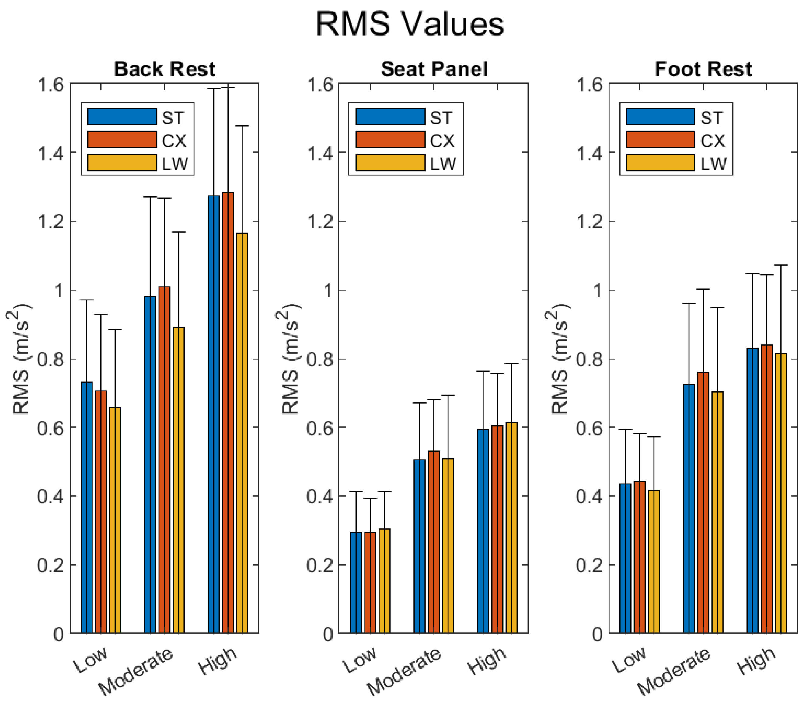
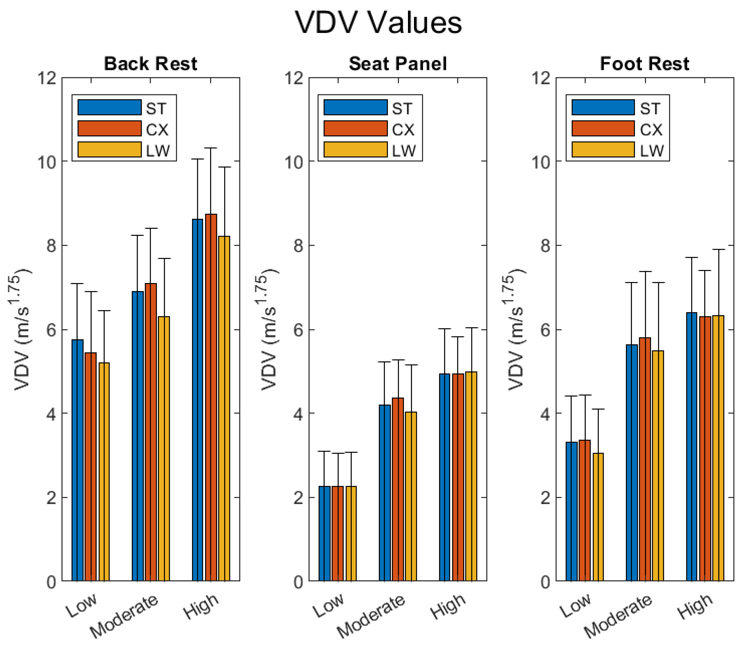
The RMS values were significantly different across wheel type in the backrest and the footrest sensor positions (p-value < 0.001), whereas at the seat panel location there was no significant difference in RMS (p-value = 0.204). In general, the WBV values for the seat panel were the lowest out of all the locations for all wheel types; the backrest position had the highest WBV values (Figure 6, Figure 7, Figure 8 and Figure 9). For the VDV values, significant differences were found at the backrest and not at the seat panel or footrest (p-value 0.58 and 0.17, respectively).
At the back rest, the Loopwheels had significantly lower RMS and VDV than the CLX and standard wheel (p < 0.005); no significant differences were found between the CLX and standard wheel. The RMS values at the footrest were significantly lower for the Loopwheels than CLX (p-value < 0.001).
Both RMS and VDV showed significant differences across intensity regions (all p-values < 0.001). A post-hoc analysis revealed that both the high- and medium-intensity regions produced significantly higher WBV values than the low-intensity region (p < 0.005); the high-intensity region produced significantly higher WBV than the medium-intensity region. This was the case for all sensor locations. There were no significant interaction effects between wheel type and intensity (all p-values > 0.2 across WBV values and sensor locations).

4.4. Rider Comfort

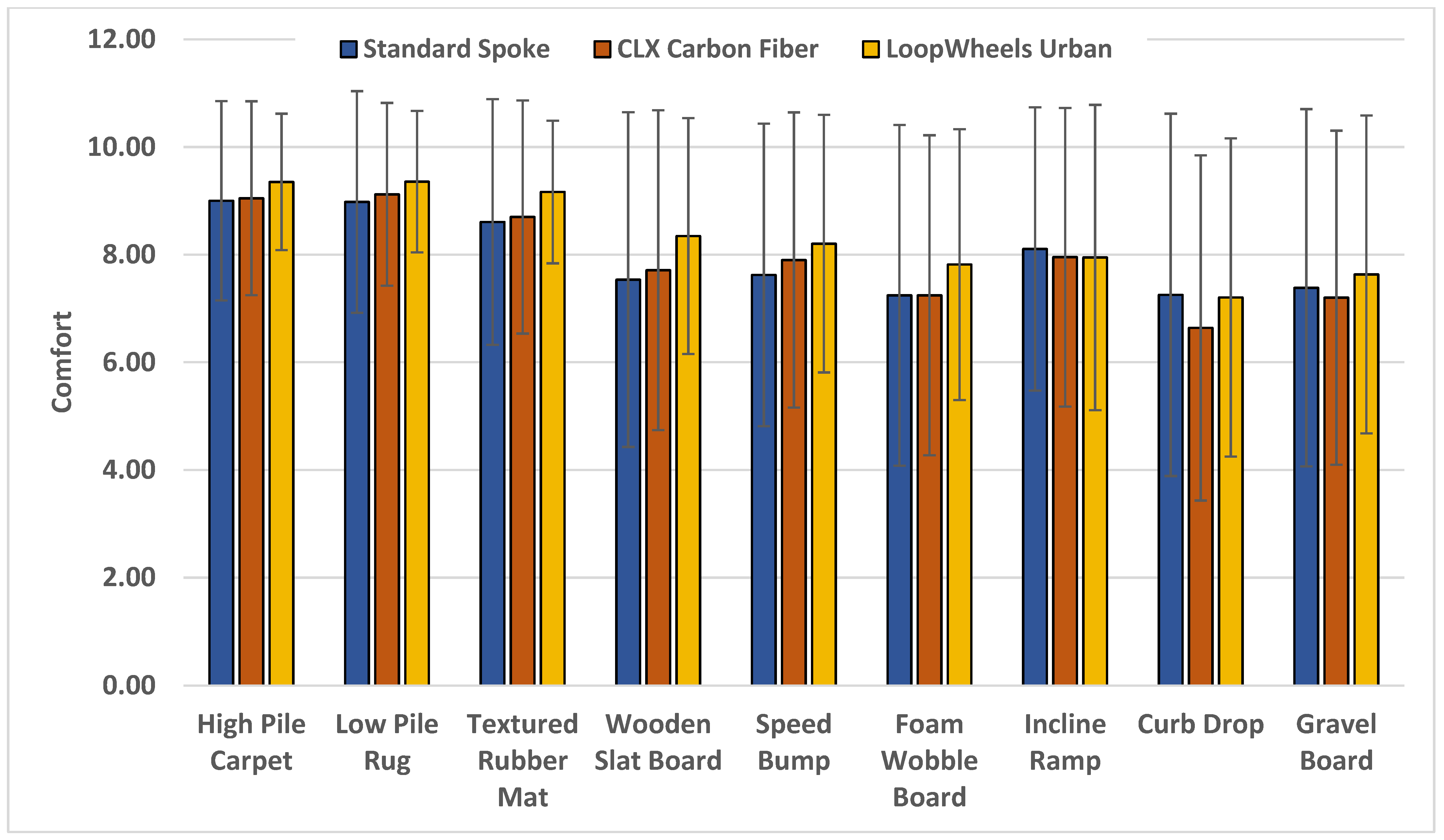
There were no significant differences in self-reported comfort for each surface and across all surfaces between wheel types (p-values > 0.7) (Figure 10 and Table 1).
No significant differences were found between wheel types for questions related to overall experience (p-values > 0.6). The values for pushrim comfort were the lowest out of all the questions asked (2.78 averaged over all three wheel types), whereas all other questions showed above-moderate experiences for stability, maneuverability, overall body comfort, and efficiency.

5. Discussion

In this study, we aimed to quantify to what extent a Loopwheels can reduce harmful vibrations and shocks in MWUs when traversing surfaces of varying roughness and when descending a curb. By involving experienced MWUs, we hoped to incorporate several elements that were not accounted for in other studies investigating the effect of suspension systems. In addition to involving experienced MWUs with spinal cord injury, we also tested them in their own wheelchairs and setup, which they were intimately familiar with. The results of this study suggest that Loopwheels Urban has the potential to lower WBV values when compared to the CLX and a standard wheel at the backrest and footrest. However, there was no difference at the seat and in perceived comfort or overall experience between the three wheels.
We found that nearly all conditions had RMS values within or exceeding the HGCZ for the 4–8 h period of exposure. However, this is assuming that MWUs are exposed to these surfaces and obstacles for 4–8 h per day, which may or may not be the case. Due to the very short exposure time over the surfaces in this study, it is not possible to determine if the in-wheel suspension significantly impacts health. Furthermore, the sensors attached to the wheelchair were not measuring the vibration exposure to the user, but rather the frame of the wheelchair; this was to control for differences in accessories between participants. Community-based studies have found that MWUs only propel for an average of one hour a day [2,6], while occupancy time is much longer. Our results for shock values are different than what was found previously in laboratory studies, where both vibration and shock were reported to be within or exceed the HGCZ [6,12,15,26]. However, it should be noted that these studies investigated surfaces and obstacles in isolation and did not report both RMS and VDV or WBV for multiple surfaces and obstacles in succession.
This study used a simulated road course approach (e.g., combined obstacle/surface type) to evaluate WBV [4], as opposed to a single surface or obstacle analysis where either an RMS or a VDV is determined based on the nature of the surface or obstacle [4]. Given that our course design consisted of sections of differing surfaces and obstacles, crest factors were calculated to determine if the basic evaluation method (RMS) was valid for describing the vibration effects. All intensity sections were found to be above the cutoff threshold (15.86 > 9), implying that traversing the sections induced occasional or transient shocks in addition to the vibrations that would be expected by some of the surfaces. These results are similar to other studies using simulated road courses where crest factors were high and both RMS and VDV were analyzed [3,14,27]. These shocks are likely coming from interfaces between surfaces, preparing before an obstacle, performing a wheelie, and/or abrupt movement in the chair, and thus these aspects, which are typical of ”real-world” propulsion, may be important to consider in a WBV analysis with wheelchair users. However, most VDV values were under the HGCZ, and this implies that the occasional or transient shocks are not enough to cause health concerns.
As expected, the RMS and VDV values increased as the region intensity increased, providing a level of validity for our approach and measures. The RMS and VDV values for the backrest and footrest showed significant differences for wheel type, but not at the seat panel. Loopwheels may be ineffective at reducing vibrations at the seat, or this lack of significant difference may be due to the way the sensor needed to be attached to the participant’s wheelchair, which differed chair to chair based on the model and from the method defined by ISO 2631. The ISO standard recommends that the accelerometer be placed between the user and the seat cushions when possible, but in cases where this is not practical, the standard outlines that placing the sensor on a rigid body is acceptable [8]. Other studies investigating vibration in MWCs have either used the same wheelchair in a controlled environment [4,12,13,26] or designed specific apparatuses to hold the sensor in place for each subject [3,6]. In this study, we utilized the participant’s existing wheelchair to preserve their unique setup rather than providing a wheelchair for the MWU to use. The seat panel sensor was attached to part of the frame under the seat panel as close to directly under the sacral joint as possible. This method was also used in other vibration studies of MWUs [4,15]. The seat panel position also produced the lowest levels of WBV compared to the backrest and the footrest, which is consistent with results from other studies investigating WBV at the seat and footrest [15].
The Loopwheels had significantly lower RMS values than the CLX and standard wheel at the backrest in the vertical direction, with a difference around 0.1 m/s2 for each. This indicates a 10% reduction in vibration exposure when using the Loopwheels. RMS was also significantly lower for the Loopwheels compared to the CLX at the footrest position, by 0.05 m/s2 (5%). Similarly, the VDV values at the backrest were significantly lower for the Loopwheels compared to the CLX and standard wheel, by about 7%, with differences of about 0.5 m/s1.75. This indicates that the Loopwheels was able to significantly reduce the amount of WBV exposure at the backrest and has some effect on decreased RMS at the footrest. To put these results into perspective when considering time of exposure, if a MWU occupies their wheelchair for an average of 13 h a day [28], a 7–10% reduction in backrest and footrest RMS would reduce the amount of exposure to harmful WBV by around an hour and potentially increase the amount of time a MWU can safely push before it becomes hazardous to health. This assumes again that MWUs would be experiencing RMS vibrations at similar levels to those measured in this study for the entire exposure period; however, since much of this occupancy time is spent not moving, the actual effect of these WBV values on health would be much lower. Lastly, the results showed no statistically significant interaction effects between the wheel type and the intensity region, meaning that the Loopwheels appears to reduce vibration and shock more than standard spoked and CLX wheels across all intensity region levels.
Our results are different from Misch et al., who reported a 12% increase in vibration (RMS) at the seat panel when using Loopwheels [15]. The differences could be explained by the different types of surfaces and the approaches used for analysis (e.g., simulated road course vs. single surface type) [15]. The nine surfaces used in this study may represent a broader range of the surfaces MWUs commonly propel over compared to the four tested in the previous study. Carpet is a very common household flooring, and curb drops, while not routinely performed, are encountered in outdoor areas; both of these surfaces were not tested in previous studies evaluating WBV and in-wheel suspension systems. Furthermore, the main outcome measure reported by Misch et al. was RMS and not VDV [15], meaning they were not able to determine the effect of suspension systems on shock with those specific surfaces. Another factor that could account for differences in results could be the human participants used in this study. Misch et al. utilized a robotic propulsion system that is unable to perform many actions a MWU would use when traversing various surfaces in their environment, such as performing wheelies and upper limb and trunk postural adjustments [15]). When performing wheelies, or lifting the casters off the ground (e.g., a common practice used for curb descent and when navigating high-roughness surfaces), the rear wheels should be able to more effectively absorb the vibration and shock. Additionally, many MWUs are now opting to use front-drive power attachments, which also lift the front casters off the ground. These technologies enable MWUs to travel more miles than without the attachment, also potentially increasing the effectiveness of the in-wheel suspension. A future study is needed to validate this assumption.
This study also found that the CLX wheels appear to have no vibration-reducing advantages over the standard wheels and produced shocks and vibrations significantly higher than the Loopwheels. This indicates that the claims made by Spinergy that the CLX wheels reduce vibrations due to the Zylon (PBO) spokes and the carbon fiber rim are not valid in these circumstances. The method of vibration attenuation in Loopwheels is more effective at reducing vibration than the novel material used for the spokes. However, the suspension system offered by Loopwheels adds additional weight to the system compared to the CLX. The Loopwheels was about 0.5 and 1.0 kg heavier than the standard spoke and the CLX wheels, respectively. This increased weight can make not only propulsion but other aspects of use more difficult, such as transportation, inclines, maintenance, etc. However, the extra weight may be necessary for effective vibration suppression. Interestingly, the Misch et al. study found that the Loopwheels increased propulsion cost by 12–16% compared to a standard wheel when using the robotic propulsion system. So, while the Loopwheels in our study showed potential in reducing vibration and shock, there may be a trade-off for propulsion cost, as is similar for other suspension systems found in wheelchairs and bikes [15]. It is a known effect in bicycles that suspension systems cause a decrease in efficiency and an increased feeling of weight [29,30], so it would make sense that these effects translate to wheelchairs.
There was no significant difference in perceived comfort across wheel types (comfort scores of standard wheel: 7.88 ± 2.53, CLX: 7.83 ± 2.38, and Loopwheels: 8.19 ± 2.10). The standard deviations were also fairly small, indicating that there is not much difference in perceived comfort between different participants. However, all the comfort values were high, reflecting that there might be possible ceiling effects preventing an accurate comparison of comfort. The comfort scores for the Loopwheels were trending towards higher than the standard wheel and CLX, which resembles what was seen in another study investigating comfort with wheelchair suspension systems [20]. No difference between comfort scores may also be beneficial, indicating that the Loopwheels, despite being heavier and potentially energy-absorbing, had no adverse effect on the comfort scores.

6. Limitations and Future Directions

One of the main limitations in this study was that we were unable to measure exactly how much vibration was transmitted to the MWU instead of the wheelchair frame. All of the accelerometers in this study were fixed to various points on the wheelchair frame directly against the rigid surface. This means that several factors, such as backrest supports and seat cushions, could impact the amount of WBV the MWU actually experiences; a soft seat cushion could reduce vibrations at the seat, or a firmer backrest could amplify shocks. Previous studies have found that the material properties of the seat cushion and the postural stability of the back supports have significant effects on vertical vibration transmissibility due to changes in posture and muscle activity [3]. While this study uses methods similar to other studies investigating vibration and following the guidelines in ISO 2631, it is not fully representative of the WBV experienced by the MWU. Previous studies have utilized a bite-bar accelerometer, along with one mounted to the seat panel, to measure vibration transmissibility from the seat through the spine [3]. Similarly, another study used an accelerometer mounted onto a bicycle helmet [26]. Head-mounted sensors introduce their own limitations, such as delayed response to seat forces and increased motion during propulsion [3,26]. Future studies should focus on measuring and monitoring the accelerations at these same positions but directly on the MWU to determine vibration transmissibility. Another limiting factor of this study was the use of standard aluminum ½” (1.27 cm) diameter circular pushrims to control the propulsion interface between wheels and participants. Many of the participants used ergonomic pushrims, which have a larger surface area or additional rubber grips. These pushrims have become more prevalent among MWUs as they assist with gripping and have been shown to reduce pain in the wrists and arms by 80–85% [31]. The results from the comfort survey indicated that participants found the study pushrims not very comfortable (average 5-point Likert scale score of 2.78), which could have impacted their overall comfort scores. It is unclear how the in-wheel suspension systems impact propulsion efficiency with human MWUs and whether they show a similar increase in energy cost as found when using a robotic propulsion system [15]. Future efforts should focus on analyzing the propulsion efficiency of in-wheel suspension systems with actual MWUs and determine other factors related to real-world and long-term use (e.g., impact on transfers, transportability, durability, pain, fatigue, etc.). Furthermore, the identification of WBV during periods of propulsion and non-propulsion are necessary. Since MWUs would not be exposed to harmful vibrations during all times of occupancy, the values found in this study and previous studies are likely to be much higher than what is actually experienced by the MWUs. Additionally, from the results found in this study, MWUs would need to propel over the surfaces tested for around six hours before they were exposed to harmful levels of WBV.

7. Conclusions

Several surfaces in the environment have the potential to cause high levels of WBV to MWUs, with limited technology to reduce the effects of the environment. In-wheel suspension systems present a potential solution for reducing the WBV and are compatible with most wheelchair models on the market today. One particular in-wheel suspension system, the Loopwheels Urban, was able to significantly reduce RMS vibrations experienced by the wheelchair frame by 7–10% at the backrest and at the footrest. The system utilizes the deformation of “C”-shaped springs to absorb the excessive amounts of shock and vibration, indicating the high potential for future adaptations of in-wheel suspension. However, further research is needed to fully understand the effects on WBV exposure regarding health during longer durations than were tested in this study. Furthermore, there was no perceived difference in comfort experienced between wheel types.

Author Contributions

Conceptualization, A.K. and A.N.; methodology, A.K. and A.N.; software, A.N. and A.B.; validation, A.K. and A.N.; formal analysis, A.N.; investigation, A.N., A.B. and L.M.; resources, A.K.; data curation, A.N. and C.S.; writing—original draft preparation, A.N.; writing—review and editing, A.K. and A.N.; visualization, A.N.; supervision, A.K.; project administration, A.K.; funding acquisition, A.K. All authors have read and agreed to the published version of the manuscript.

Funding

This research was funded by the Craig H. Neilsen Foundation Project 651619.

Data Availability Statement

The data are available upon request from the corresponding author.

Conflicts of Interest

The authors declare no conflicts of interest. The funders had no role in the design of the study; in the collection, analyses, or interpretation of data; in the writing of the manuscript; or in the decision to publish the results.

Appendix A. VAS Comfort Survey

Wheelchair Ride Comfort and Ergonomics Questionnaire
< User Survey >
 
 Enter Device ID for this Evaluation ____________
 Please answer the following questions by marking your answers with a cross on the corresponding line, where the ends of the lines equal the strength of your response. Mark only one answer per question unless directed.
 For the following questions, please use the following scale: 0 = extremely uncomfortable; 10 = extremely comfortable.
 
  • How comfortable were you when pushing your wheelchair over the following surfaces?
 
 High-Pile Carpet
   
    
0 10
 
 Low-Pile Carpet
    
    
0 10
 
 Textured Rubber Mat
   
    
0 10
 
 Wooden Slat Board
    
    
0 10
 
 Speed Bump
    
    
0 10
 
 Foam Wobble Board
   
    
0 10
 
 Incline Ramp
    
    
0 10
 
 4-inch Curb Drop
    
    
0 10
 
 Simulated Gravel
    
    
0 10
 
2.
For the following questions, please select your response based on your overall experience when pushing over these surfaces.
 
How stable or secure did you feel when pushing over these surfaces?
______Not at All
______Fairly
______Moderately
______Very
______Extremely
 
Overall, how easy was it to maneuver over these surfaces?
______Not at All
______Fairly
______Moderately
______Very
______Extremely
 
How comfortable were your hands on the pushrim when pushing over these surfaces?
______Not at All
______Fairly
______Moderately
______Very
______Extremely
 
How comfortable overall did your body feel when pushing over these surfaces?
______Not at All
______Fairly
______Moderately
______Very
______Extremely
 
How efficient did you feel when pushing over these surfaces?
______Not at All
______Fairly
______Moderately
______Very
______Extremely
 
Are there any other comments you would like to provide?
 ________________________________________________________________________________________________________________________________________________________________________________________________________________________________________________________________________________________________________________________________________

Appendix B. Data Post-Processing

Appendix B.1. Gravity Rotation

Figure A1. The plots above show the raw and rotated acceleration data from the first second of a static position. Original coordinate system is shown by x, y, and z, and the rotated system is x’, y’, and z’. As shown, in the rotated system, gravity is only applied in the z’ direction.
Vibration 07 00023 g0a1

Appendix B.2. Vibration Filtering

Figure A2. The plot above shows the raw and filtered vertical acceleration from two seconds of a trial.
Vibration 07 00023 g0a2

Appendix B.3. Intensity Region Separation

Figure A3. The plot above shows the acceleration measured by a sensor for the whole obstacle course. The intensity regions are defined by their start (green line) and their end (red line). Only data within each region was used to calculate WBV values.
Vibration 07 00023 g0a3
Intensity region intervals were identified manually by visual analysis of the raw acceleration data. Since the participants are asked to start from a rest and end with a complete stop, the boundaries were chosen to include the region with steady-state motion.

References

  1. Misch, J.; Sprigle, S. Estimating whole-body vibration limits of manual wheelchair mobility over common surfaces. J. Rehabil. Assist. Technol. Eng. 2022, 9, 20556683221092322. [Google Scholar] [CrossRef] [PubMed]
  2. Tolerico, M.L.; Ding, D.; Cooper, R.A.; Spaeth, D.M.; Fitzgerald, S.G.; Cooper, R.; Kelleher, A.; Boninger, M.L. Assessing mobility characteristics and activity levels of manual wheelchair users. J. Rehabil. Res. Dev. 2007, 44, 561–571. [Google Scholar] [CrossRef] [PubMed]
  3. DiGiovine, C.P.; Cooper, R.A.; Wolf, E.; Fitzgerald, S.G.; Boninger, M.L. Analysis of whole-body vibration during manual wheelchair propulsion: A comparison of seat cushions and back supports for individuals without a disability. Assist. Technol. 2003, 15, 129–144. [Google Scholar] [CrossRef] [PubMed]
  4. Lariviere, O.; Chadefaux, D.; Sauret, C.; Thoreux, P. Vibration Transmission during Manual Wheelchair Propulsion: A Systematic Review. Vibration 2021, 4, 444–481. [Google Scholar] [CrossRef]
  5. Boninger, M.L.; Cooper, R.A.; Fitzgerald, S.G.; Lin, J.; Cooper, R.; Dicianno, B.; Liu, B. Investigating neck pain in wheelchair users. Am. J. Phys. Med. Rehabil. 2003, 82, 197–202. [Google Scholar] [CrossRef] [PubMed]
  6. Garcia-Mendez, Y.; Pearlman, J.L.; Boninger, M.L.; Cooper, R.A. Health risks of vibration exposure to wheelchair users in the community. J. Spinal Cord. Med. 2013, 36, 365–375. [Google Scholar] [CrossRef] [PubMed]
  7. Orelaja, O.A.; Wang, X.; Ibrahim, D.S.; Sharif, U. Evaluation of Health Risk Level of Hand-Arm and Whole-Body Vibrations on the Technical Operators and Equipment in a Tobacco-Producing Company in Nigeria. J. Healthc. Eng. 2019, 2019, 5723830. [Google Scholar] [CrossRef] [PubMed]
  8. International Standards Organization 2631-1; Mechanical Vibration and Shock—Evaluation of Human Exposure to Whole-Body Vibration—Part 1: General Requirements. ISO: Geneva, Switzerland, 1997.
  9. International Standards Organization 2631-5; Mechanical Vibration and Shock—Evaluation of Human Exposure to Whole-Body Vibration—Part 5: Method for Evaluation of Vibration Containing Multiple Shocks. ISO: Geneva, Switzerland, 2018.
  10. Wolf, E.J.; Cooper, M.S.; DiGiovine, C.P.; Boninger, M.L.; Guo, S. Using the absorbed power method to evaluate effectiveness of vibration absorption of selected seat cushions during manual wheelchair propulsion. Med. Eng. Phys. 2004, 26, 799–806. [Google Scholar] [CrossRef] [PubMed]
  11. Griffin, M.J. A comparison of standardized methods for predicting the hazards of whole-body vibration and repeated shocks. J. Sound Vib. 1998, 215, 883–914. [Google Scholar] [CrossRef]
  12. Cooper, R.A.; Wolf, E.; Fitzgerald, S.G.; Boninger, M.L.; Ulerich, R.; Ammer, W.A. Seat and footrest shocks and vibrations in manual wheelchairs with and without suspension. Arch. Phys. Med. Rehabil. 2003, 84, 96–102. [Google Scholar] [CrossRef] [PubMed]
  13. Kwarciak, A.M. Performance Analysis of Suspension Manual Wheelchairs. Master’s Thesis, University of Pittsburgh, Pittsburgh, PA, USA, 2004. [Google Scholar]
  14. Chénier, F.; Aissaoui, R. Effect of wheelchair frame material on users’ mechanical work and transmitted vibration. Biomed. Res. Int. 2014, 2014, 609369. [Google Scholar] [CrossRef] [PubMed]
  15. Misch, J.P.; Liu, Y.; Sprigle, S. Effect of Wheels, Casters and Forks on Vibration Attenuation and Propulsion Cost of Manual Wheelchairs. IEEE Trans. Neural Syst. Rehabil. Eng. 2022, 30, 2661–2670. [Google Scholar] [CrossRef] [PubMed]
  16. Mester, J.; Spitzenfeil, P.; Schwarzer, J.; Seifriz, F. Biological reaction to vibration—implications for sport. J. Sci. Med. Sport 1999, 2, 211–226. [Google Scholar] [CrossRef] [PubMed]
  17. Skendraoui, N.; Bogard, F.; Murer, S.; Fabien, B.; Abbès, B.; Polidori, G.; Nolot, J.B.; Erre, D.; Odof, S.; Taiar, R. Experimental Investigations and Finite Element Modelling of the Vibratory Comportment of a Manual Wheelchair. In Human Systems Engineering and Design, Proceedings of the 1st International Conference on Human Systems Engineering and Design (IHSED2018): Future Trends and Applications, CHU-Université de Reims Champagne-Ardenne, France, 25–27 October 2018; Ahram, T., Karwowski, W., Taiar, R., Eds.; Springer: Berlin/Heidelberg, Germany, 2019. [Google Scholar]
  18. Kitazaki, S.; Griffin, M.J. Resonance behaviour of the seated human body and effects of posture. J. Biomech. 1998, 31, 143–149. [Google Scholar] [CrossRef] [PubMed]
  19. Loopwheels. Loopwheels Brochure. 2018. Available online: https://loopwheels.com/wp-content/uploads/2018/12/Loopwheels-Brochure.pdf (accessed on 1 January 2024).
  20. Giwnewer, U.; Rubin, G.; Friedman, A.; Rozen, N. User Assessment of a Novel Suspension for a Wheelchair—A Prospective, Randomized, Double Blind Trial. Geriatr. Orthop. Surg. Rehabil. 2020, 11, 2151459320983268. [Google Scholar] [CrossRef] [PubMed]
  21. Spinergy. “CLX”. Available online: https://spinergy.com/products/clx?variant=41112136548540 (accessed on 1 January 2024).
  22. Brault, M.W. Americans with Disabilities: 2010; US Department of Commerce, Economics and Statistics Administration: Washington, DC, USA, 2012.
  23. Duvall, J.; Sinagra, E.; Cooper, R.; Pearlman, J. Proposed pedestrian pathway roughness thresholds to ensure safety and comfort for wheelchair users. Assist. Technol. 2016, 28, 209–215. [Google Scholar] [CrossRef] [PubMed]
  24. DiGiovine, M.M.; Cooper, R.A.; Boninger, M.L.; Lawrence, B.M.; VanSickle, D.P.; Rentschler, A.J. User assessment of manual wheelchair ride comfort and ergonomics. Arch. Phys. Med. Rehabil. 2000, 81, 490–494. [Google Scholar] [CrossRef] [PubMed]
  25. Racine, J.S. Rstudio: A platform-independent ide for r and sweave. J. Appl. Econom. 2012, 27, 167–172. [Google Scholar] [CrossRef]
  26. Requejo, P.S.; Kerdanyan, G.; Minkel, J.; Adkins, R.; Waters, R. Effect of rear suspension and speed on seat forces and head accelerations experienced by manual wheelchair riders with spinal cord injury. J. Rehabil. Res. Dev. 2008, 45, 985–996. [Google Scholar] [CrossRef] [PubMed]
  27. Hischke, M.; Reiser, R.F., 2nd. Effect of Rear Wheel Suspension on Tilt-in-Space Wheelchair Shock and Vibration Attenuation. PMR 2018, 10, 1040–1050. [Google Scholar] [CrossRef]
  28. Sonenblum, S.E.; Sprigle, S.; Lopez, R.A. Manual wheelchair use: Bouts of mobility in everyday life. Rehabil. Res. Pract. 2012, 2012, 753165. [Google Scholar] [CrossRef] [PubMed]
  29. Wang Associate Instructor, E.L.; Hull Professor, M.L. A Model for Determining Rider Induced Energy Losses in Bicycle Suspension Systems. Veh. Syst. Dyn. 1996, 25, 223–246. [Google Scholar] [CrossRef]
  30. Herrick, J.E.; Flohr, J.A.; Wenos, D.L.; Saunders, M.J. Comparison of Physiological Responses and Performance Between Mountain Bicycles With Differing Suspension Systems. Int. J. Sports Physiol. Perform. 2011, 6, 546–558. [Google Scholar] [CrossRef] [PubMed]
  31. Koontz, A.M.; Yang, Y.; Boninger, D.S.; Kanaly, J.; Cooper, R.A.; Boninger, M.L.; Dieruf, K.; Ewer, L. Investigation of the performance of an ergonomic handrim as a pain-relieving intervention for manual wheelchair users. Assist. Technol. 2006, 18, 123–143, quiz 145. [Google Scholar] [CrossRef] [PubMed]
Figure 1. The diagram above shows how the in-wheel suspension system works when it encounters an obstacle. As shown, the axle hub of the wheel is able to deflect relative to the rim of the wheel and stay level relative to the ground. The dashed line represents the level of the axle, and the blue region represents the surface.
Vibration 07 00023 g001
Figure 2. The surfaces, obstacles, and course layout used for this study. The course was split into three intensity regions and three surfaces/obstacles in each region. These regions were physically marked off with tape on the floor.
Vibration 07 00023 g002
Figure 3. The three different wheel types used in this study.
Vibration 07 00023 g003
Figure 4. The diagram above shows the approximate locations of where the Shimmer3 sensors were placed on the wheelchair along with the respective coordinate system.
Vibration 07 00023 g004
Figure 5. The image above shows differences in sensor position between two different manual wheelchairs, a ROGUE (1) and a PantheraX (2). Overall (A1,A2), footrest (B1,B2), seat panel (C1,C2), and back rest (D1,D2) differences are shown along with sensor orientation.
Vibration 07 00023 g005
Figure 6. Average RMS values over all participants for each wheel, sensor location, and intensity region. Error bars show standard deviation.
Vibration 07 00023 g006
Figure 7. Average VDV over all participants for each wheel, sensor location, and intensity region. Error bars show standard deviation.
Vibration 07 00023 g007
Figure 8. RMS mean values calculated for each wheel type at each sensor location. Error bars signify the standard deviation, and statistically significant differences are reported by * and ** (p-value < 0.05 and 0.001, respectively). (ST: standard, CX: CLX, and LW: Loopwheels).
Vibration 07 00023 g008
Figure 9. The VDV mean values calculated for each wheel type at each sensor location. Error bars show the standard deviation, and statistically significant differences are reported by ** (p-value < 0.001). (ST: standard, CX: CLX, and LW: Loopwheels).
Vibration 07 00023 g009
Figure 10. Mean self-reported comfort scores for each surface and wheel type.
Vibration 07 00023 g010
Table 1. Mean and standard deviation of the overall experience questions for each wheel type.
Wheel TypeStatisticStable/SecureManeuverabilityPush-Rim ComfortOverall Body ComfortEfficiency
Standard SpokeMean3.53.42.93.43.2
Std Dev1.21.11.31.11.1
CLXMean3.83.72.73.53.4
Std Dev1.01.11.51.11.1
LoopwheelsMean3.63.52.93.73.8
Std Dev1.41.21.51.01.0
Disclaimer/Publisher’s Note: The statements, opinions and data contained in all publications are solely those of the individual author(s) and contributor(s) and not of MDPI and/or the editor(s). MDPI and/or the editor(s) disclaim responsibility for any injury to people or property resulting from any ideas, methods, instructions or products referred to in the content.