1. Introduction
The vibration of structures can be seen as a superposition of elastic waves that are reflected within boundaries. The term “guided wave” is thus used to indicate a wave formed by multiple reflections from boundaries and being guided along the structure (also referred to as a waveguide). At particular frequencies of vibration, the waves reflected at the structure terminations interfere with incident waves, forming the so-called standing waves (or vibrational modes). The dynamic response of structures can be thus described both in terms of waves or vibrations. Vibrations describe the response of a whole structure, allowing a general analysis of various effects related to standing waves (e.g., natural frequencies and mode shapes). The wave approach enables a deeper and local investigation of the structural response. The study of free wave propagation is mainly associated with the computation of dispersion curves (which show the trend of wavenumbers, or wave velocities, against frequencies) and wave mode shapes that represent the local deformation of the structure associated with each wave. The forced wave propagation is instead associated with the structural response due to a single wave or a combination of waves.
In recent decades, thanks to their ability to travel long distances and detect discontinuities or minor defects along their propagation path, guided waves have been widely exploited by researchers for applications of structural health monitoring (SHM) [
1], non-destructive evaluation (NDE) techniques [
2], and material characterisation of test structures [
3]. A preliminary task to accomplish when dealing with guided wave problems is to determine the dispersion curves, which provide useful information about the number and types of propagating waves at any frequency, the attenuation, the frequency-dependent velocities (dispersion), and other wave properties of interest.
Analytical and matrix-based solution methods [
4] have been employed for many years to study the propagation of guided waves. However, their inadequacy in generating dispersion curves for complex-shaped waveguides or inhomogeneous complex materials [
5,
6,
7] has led researchers to resort to numerical approaches based on finite-element (FE) methods. These traditional 3D finite-element approaches become unsuitable though when simulating large domains or high-frequency applications due to the fine mesh required and the consequent high computational cost. A possible solution to adopt when simulating problems with open boundaries is the use of a perfectly matched layer (PML), an artificial layer designed to absorb waves from a computational region, thus avoiding the problem of reflected waves. Alternatively, numerous studies on decreasing computational cost are present in the literature under the names of boundary element method (BEM), finite difference method (FDM), and wave finite-element (WFE) method, to mention a few. However, as reported in [
8], these numerical approaches present advantages and disadvantages in modelling different types of guided wave problems.
Another method that has been widely adopted by researchers for solving wave propagation problems in uniform waveguides is the semi-analytical finite-element (SAFE) method [
6], also known in the literature as wavenumber finite-element method [
9] or 2.5D finite-element method [
10]. It involves an FE-like procedure to discretise only the 2D cross-section of the waveguide and an analytical solution of the displacement field in the direction of propagation, hence the name semi-analytical. A system of linear equations is constructed with the frequency and wavenumbers as unknowns, which are then solved through standard eigenvalue routines. The SAFE method has many advantages for guided wave calculation. In particular, for waveguides that are infinitely long in one dimension, SAFE is superior to pure FEM since exact analytical representations are used for one or two dimensions of the waveguide, reducing the computational cost.
The calculation of dispersion curves can be conveniently performed by taking advantage of the commercial FE software COMSOL Multiphysics. For periodic structures, the most common approach is to use what COMSOL refers to as Floquet boundary conditions [
11]. Compared to the SAFE method, this approach assumes a geometric periodicity of the domain of the problem rather than a displacement solution, providing a fast computation speed and a simple implementation. However, it does not allow for a reduction in domain dimension and a consequent decrease in computational cost. Alternatively, dispersion curves can be computed in COMSOL by following the SAFE method implementation proposed by Predoi [
12].
The main contribution of this paper is to propose an extension of this method that enables the extraction from COMSOL of the assembled mass and stiffness SAFE matrices to solve both free and forced wave propagation in the Matlab environment. This is possible thanks to a powerful tool of this software that allows the user to set up and solve COMSOL models directly from Matlab. This results in customised software that takes advantage of both the potential of commercial FE software and the power of Matlab without worrying about compatibility issues. By extracting the assembled SAFE matrices from COMSOL, the user can thus manipulate them in Matlab to obtain further results, such as the forced wave propagation object of this paper. This could, in principle, be achieved in any other software environment; the advantage of using Matlab is that it can be done seamlessly through the Livelink COMSOL’s tool.
After presenting an overview of the SAFE framework for free wave propagation, its implementation in COMSOL, as proposed by Predoi [
12], is briefly introduced to assist the extraction procedure from COMSOL of the assembled SAFE matrices. A formulation for the forced response is then presented. This allows the prediction of the vibration response to various types of excitation, in the frequency domain, through the expression of the frequency response function (FRF). The framework for computing forced wave propagation finds applications in many fields of study, including the modelling of wave scattering at discontinuities and wave generation in coupled fluid-structure systems such as pipes. Finally, two numerical examples are introduced to validate the proposed SAFE method implementation. A simply supported plate strip of known dispersion relationships is modelled and used to validate the SAFE matrix extraction procedure. A waveguide with a more complex geometry is also modelled and used to verify the correct implementation of the forced response formulation. Its forced wave propagation will be computed and compared with the one obtained by a conventional FE model of the same structure to whom a PML is applied at the free terminations.
2. Overview of the SAFE Framework
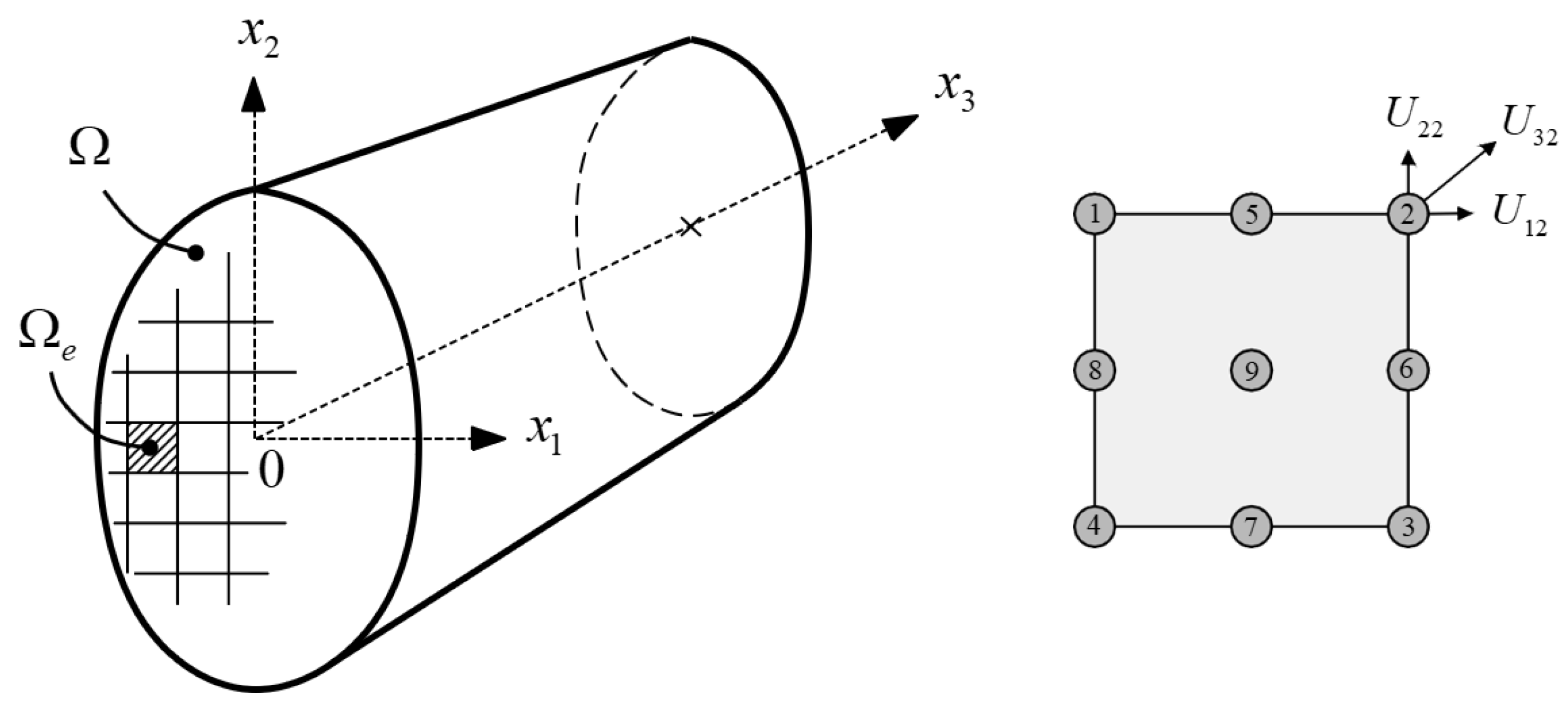
The SAFE method represents, presently, one of the most established numerical approaches for predicting elastic wave propagation in one-dimensional structures of arbitrary cross-section. Consider an elastic waveguide whose cross-section lies in the
-plane with waves propagating harmonically along the
-axis, as depicted in
Figure 1.
The mathematical formulation starts from the displacement equations of motion, also known as Navier’s equation of motion, which represents the most general form of wave equation:
where
are the terms of the elasticity tensor,
are the components of the displacement field,
is the mass density and
t is the time variable. In the formulation, the three-dimensional elasticity approach is considered, thus avoiding simplifications to the elastic tensor and displacement field. The geometrical and material properties are assumed to be uniform along the direction of propagation, allowing a separation of the cross-section plane domain from the out-of-plane wave propagation domain. A solution of Equation (
1) may be hence expressed as
where
is the amplitude of the displacement field,
is the imaginary unit,
is the wavenumber in the propagation direction and
is the angular frequency.
After substitution of Equation (
2) into Equation (
1) and some intermediary transformations, one obtains
with summation over the indices
and
. Analogously, by defining as
the traction vector, and
the components of the outward unit vector normal to the boundaries
of the elastic domain
, the Newmann boundary condition is expressed as
with summation over the indices
and
.
Equation (
3) leads to a system of dispersion relationships, which, to be solved, requires the calculation of the derivatives of
. A numerical approximation of the displacement field is thus necessary, leading to the application of a finite-element discretisation. This allows one to reformulate the strong form of Equation (
3) as a similar quadratic eigenvalue problem. In the next section, as an alternative to a laborious FE discretisation manually implementable in Matlab or a similar environment, a method that takes advantage of the FE software COMSOL to perform the calculation of dispersion curves is presented.
3. Computing Dispersion Curves by COMSOL Multiphysics Software
One of the advantages of COMSOL is the possibility to use a set of mathematical interfaces for equation-based modelling. In particular, among its options, it allows one to implement and solve user-defined Partial Differential Equations (PDE) through its Coefficient Form PDE interface. The input formalism for eigenvalue problems of this interface has the general expressions [
13]:
Equation (
5) is the generic form of PDE which must be satisfied in the computational domain
, while Equation (
6) represents the generalised Neumann boundary condition. In such equations,
is a vector containing the unknown dependent variables,
is the eigenvalue, ∇ is the nabla operator, and
n is the outward unit normal vector on the domain boundary
. The remaining coefficients are user-specified coefficient matrices that can admit complex values, which is essential for viscoelastic materials.
A reformulation of the SAFE problem, as given in Equation (
3), into the COMSOL formalism was proposed by Predoi et al. [
12]. By setting
, Equation (
5) can be expressed as
and a similar expression can be obtained for the boundary condition of Equation (
6).
The SAFE Equation (
3) represents a quadratic eigenvalue problem in wavenumber
k. To cast it into the linear form of Equation (
7), a new vector variable
is introduced by the equation
in which
is an arbitrary diagonal matrix, and the wavenumber
k corresponds to the eigenvalue
. By denoting with
the new set of variables to be determined, the coefficient matrices are thus given as
where
represents a zero matrix of appropriate dimensions. The submatrices are given by
where
is the contracted notation for the elasticity tensor,
is the material density and
the angular frequency.
The above coefficient matrices, as given in [
12], allow the user to easily implement the SAFE problem on COMSOL, avoiding the laborious implementation of the FE discretisation in Matlab or a similar environment. However, this method is limited to only the computation of the dispersion curves. To overcome this limitation, the next section proposes an extension of this method that combines COMSOL and Matlab to solve problems of both free and forced wave propagation.
4. SAFE Method for Free and Forced Wave Propagation through Livelink for Matlab
As previously described, through the Coefficient Form PDE interface, COMSOL offers a simple method to implement the SAFE problem and perform the calculation of dispersion curves. Moreover, another important feature of this software is the Livelink for Matlab, a tool that allows the user to create a link between the COMSOL and Matlab environments. With this functionality, it is possible to use Matlab as a scripting tool to set up and solve COMSOL models and extract data such as FE mesh coordinates and other useful information as Matlab variables.
In this section, by combining these COMSOL features, a procedure to extract the global mass and stiffness SAFE matrices is proposed, thus allowing the carrying out of the SAFE modelling of any arbitrary waveguide and solving of both free and forced wave propagation problems entirely from the MATLAB environment. This will result in customised software that takes advantage of both the potential of commercial FE software and the power of Matlab without worrying about compatibility issues.
4.1. Extraction of the SAFE Matrices from COMSOL Multiphysics
The SAFE matrix extraction procedure starts from the reformulation of the SAFE problem into the COMSOL formalism, as provided by Predoi [
12]. By setting
in Equation (
5) one obtains
This time, with the only intent to extract the SAFE matrices, the following coefficient matrices are considered:
They are the same as the ones presented in Equation (
9) with the difference that they are all real and the coefficient matrix
is set to zero. Moreover, the following submatrix
m has been modified such that the dependency from the angular frequency,
, is omitted:
With this new set of coefficient matrices and the vector of variable
introduced by Equation (
8), the system of Equations (
11) can be rewritten in matrix form as
where the wavenumber
k corresponds to the eigenvalue
.
After performing SAFE modelling through the Livelink for Matlab tool, it is possible to export to Matlab the COMSOL system matrices
K and
D by calling the function mphmatrix [
13]. The system matrices are returned by COMSOL in sparse format and thus need to be converted in Matlab to the full (or dense) format to enable the extraction of the single SAFE matrices. Sketched in
Table 1 and
Table 2 are the system matrices obtained with the above coefficient matrices after being converted to the full format. They are matrices of order
where, for solid elements,
N is three times the total number of nodes, composed of blocks of 6 × 6 matrices. As one can notice, every single block corresponds to the system of Equations (
14), but with their order switched. In particular, it emerges that the coefficient matrix
controls the system matrix
D, while the remaining coefficients control the system matrix
K.
At this point, from the system matrices K and D, it is straightforward to extract in Matlab the global mass and stiffness SAFE matrices , , , and , of order N, by concatenating opportunely the rows and columns corresponding to the single submatrices.
4.2. Free Wave Propagation
Once the assembled mass and stiffness SAFE matrices have been extracted from COMSOL, the system of dispersion Equation (
3) can be rewritten in matrix form as
where
Equation (
15) represents a twin-parameter eigenvalue problem in wavenumber
k and angular frequency
, thus can be solved using two alternative approaches [
14]. One approach is to propose a real wavenumber
k and solve it as a linear generalised eigenvalue problem in
. Although simpler, this approach allows only the computation of propagating modes in undamped systems. For this reason, the most common approach consists of proposing the frequency
and solving it as a second-order polynomial eigenvalue problem in
. However, to be solved with standard numerical solvers, it must be recast into a linear form by doubling its algebraic size:
where
By solving Equation (
16) for a given frequency
,
complex wavenumbers
are returned by the eigenvalues in pairs, accounting for positive-going and negative-going waves (denoted by subscripts
hereafter). These can be grouped accordingly and written, for later convenience, as
For undamped waveguides, the purely real and imaginary wavenumber solutions appear in pairs of opposite signs and correspond, respectively, to propagating and evanescent waves. The fully complex wavenumbers represent inhomogeneous evanescent waves (decaying but oscillatory); they appear in quadruples of complex conjugates and opposite signs (i.e., if
k is an eigenvalue, then
,
and
are also eigenvalues). In the presence of material damping, the structure of the eigensolutions changes. Every root is complex and appears in pairs of opposite signs, therefore a straightforward distinction between propagating and evanescent waves is no longer possible [
14,
15].
The corresponding wave mode shapes U
are obtained from the top half of the eigenvectors
. They can be separated similarly for each region of the waveguide and written in matrix form as
From the
eigensolutions, the nodal displacements (i.e., the DOFs) in either region of the waveguide are obtained by a linear combination of corresponding wave modes
and wavenumbers
as
in which the harmonic time dependence
is assumed and omitted.
4.3. Forced Response Formulation
In this work, the forced response for the SAFE method is implemented through the wave approach, as reported in [
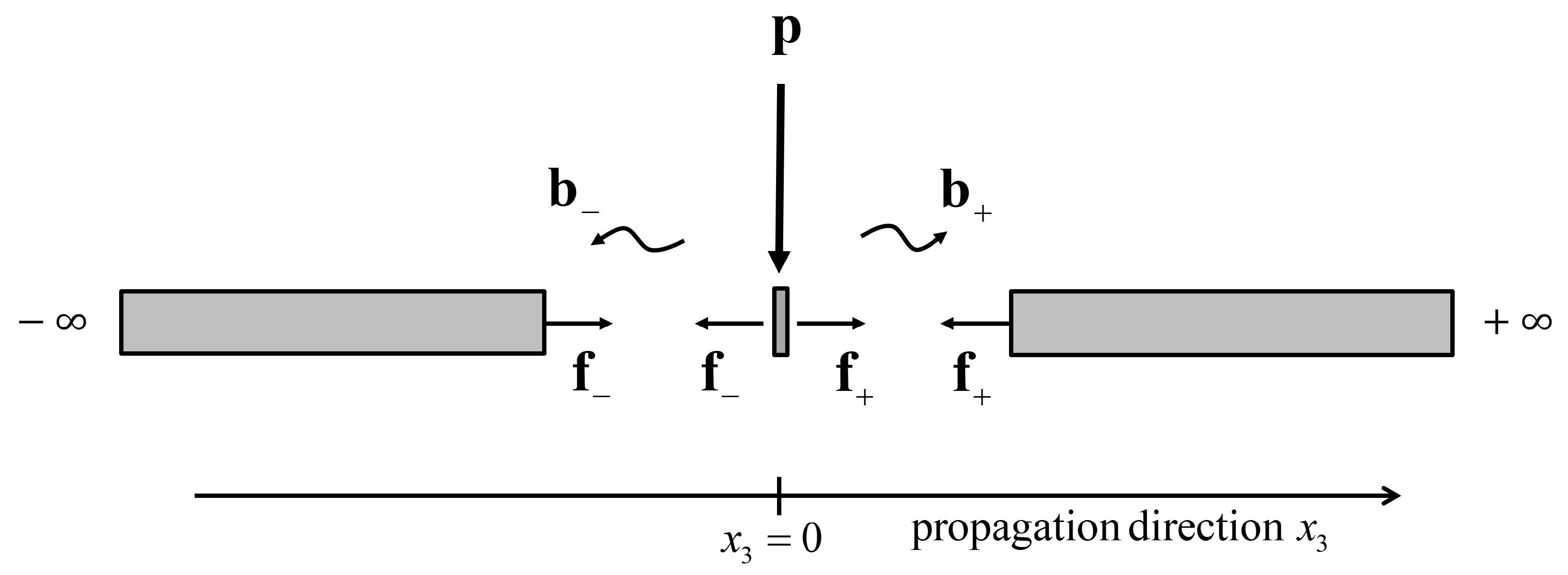
16]. The formulation starts from the expressions of displacement continuity and force equilibrium conditions for a cross-section of the waveguide to which the external loads are applied. As sketched in
Figure 2, the origin of the axis of propagation,
, is conveniently positioned at the point of application of the loads, from which propagating and evanescent waves in either region of the waveguide are expected to be generated. In the following, as for Equations (
20), the harmonic time dependence
is assumed and omitted to simplify the notation.
By denoting as
the
N-dimensional vector of the external forces applied to the cross-section nodes at
,
and
the vectors of the internal nodal forces of the waveguide, respectively, in the positive and negative wave propagation direction, the aforementioned conditions can be expressed as
The vector of nodal displacements related to the positive-going waves can be written in matrix form as
where
is an
diagonal matrix of propagation terms corresponding to each positive-going wave, i.e.,
and
is an
N-dimensional vector of unknown wave amplitudes arising from the excitation. Similarly, the nodal displacements related to the negative-going waves are expressed as
where
and
are analogously defined.
The vector of the internal nodal forces, according to the formulation used in [
17], is expressed as
The continuity and equilibrium conditions of Equations (
21) forms a linear system of
equations with the unknown wave amplitudes,
and
, as solutions to be determined. The internal nodal forces immediately on either side of the external forces can be obtained by substituting for
and
from Equations (
22) and (
24) into Equation (
25) and evaluating at
to give
It follows that the system of linear Equations (
21) can be expressed in matrix form as
where
The wave amplitudes are then obtained from Equations (
27) by inversion of
as
Substituting for
and
from Equations (
29) into Equations (
22) and (
24) gives the vector of nodal displacements, at any position
along the waveguide and at any frequency, as
where receptance matrices
and
are given by
Consider now a case study where a single transfer function is sought relating the response at the
DOF to a single input at the
DOF, i.e.,
Substituting
into Equation (
30) and extracting the
element of the response vector gives the single-input/singe-output relationship for either region of the waveguide,
The nodal acceleration can be readily derived from the nodal displacement and expressed as
5. Validation of the Implemented SAFE Method
In this section, as a validation of the proposed SAFE method implementation, two numerical examples are presented. A model of a simply supported plate strip of known dispersion relationships is first implemented to validate the SAFE matrix extraction procedure. Cut-off frequencies and dispersion curves for bending waves are computed and compared with the corresponding analytical solutions. A few examples of wave mode shapes are also presented.
Successively, a waveguide of more complex geometry is modelled and used to verify the correct implementation of the forced response formulation. Its SAFE results are computed and compared with the ones obtained by a conventional FE model of the same structure to which a PML is applied at the free terminations. The two models have been implemented using MATLAB 2018 and COMSOL Multiphysics 5.5.
5.1. A Simply Supported Plate Strip Model
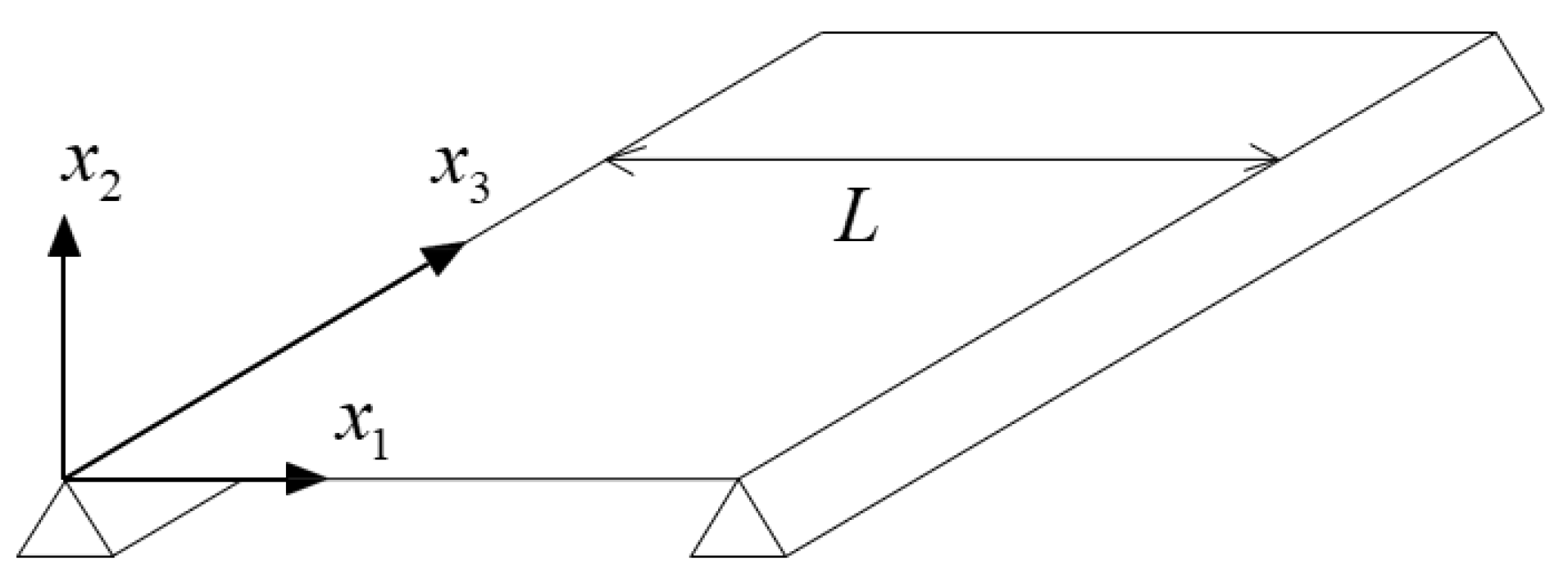
Consider an infinitely long plate of uniform width,
L, located between boundaries that provide simple supports, as depicted in
Figure 3. The plate is thin, isotropic and undamped.
For such a plate, the analytical expression for free bending wavenumber is given by [
18] as
where
is the bending stiffness,
E the Young’s modulus,
the Poisson’s ratio,
h the thickness of the plate strip,
the mass density and
the angular frequency.
For the simply supported boundary condition along the plate edges,
, the wave modes take the form of a standing pattern proportional to
with
n being an integer. The wavenumber along the direction of propagation
is thus given by
Substituting
into the dispersion Equation (
36) gives the cut-off frequency of the
wave mode as
A numerical SAFE model for free wave propagation of such a structure is then implemented. The plate, made of aluminium, has a rectangular cross-section of 300 mm by 3 mm and is assumed to be uniform, isotropic, and homogeneous. Its material properties are: , and .
The cross-section has been discretised by 32 four-sided elements, which use quadratic Lagrange shape functions, with a total of 195 nodes and corresponding 585 DOFs, as shown in
Figure 4. No damping is assumed in the model and the upper and lower boundaries of the cross-section are considered to be traction-free. After removing the DOFs associated with the boundary conditions, there are 581 resulting DOFs for the model.
It is worth highlighting that the 2D cross-section of the waveguide has been discretised using the COMSOL “mapped” mesh, which allows the user to control the number of elements and their distribution along the edges. This has allowed obtaining the optimal meshing by conducting a study that evaluates the convergence of the cut-off frequencies when using different mesh configurations.
At any given frequency, the SAFE method can predict all the possible elastic waves in the waveguide propagation direction. In this example, the eigenvalue problem of Equation (
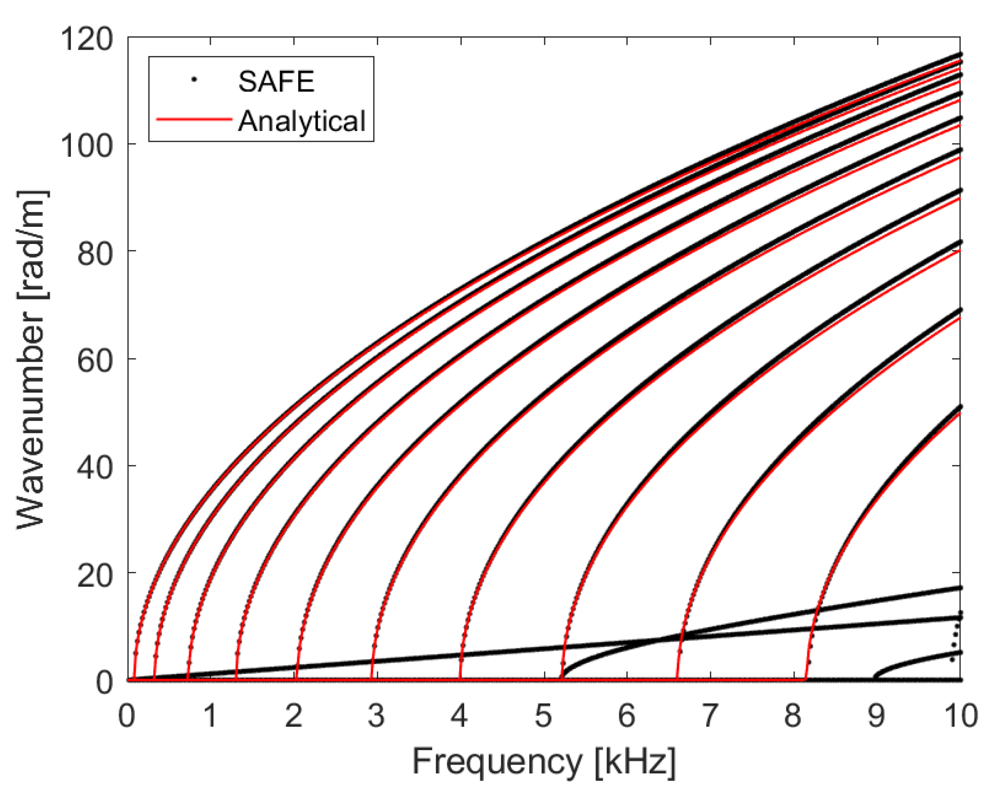
16) has been solved for a frequency bandwidth of 10 kHz and a frequency resolution of 20 Hz. In
Figure 5, the numerical dispersion curves, in the form of wavenumber against frequency, are overlaid with the analytical solutions obtained from Equation (
36). The SAFE solutions are plotted by black discrete dots, whereas the analytical solutions are plotted in red. As one can notice, the analytical wave solutions overlay the corresponding numerical ones validating the SAFE model. The remaining curves consist of a zero-order wave mode, which propagates at all frequencies, and two high-order wave modes that cut off at approximately 5 and 9 kHz.
In
Table 3, a comparison between analytical and numerical solutions of the first six cut-off frequencies is reported. The analytical solutions are calculated from Equation (
37), whereas the corresponding numerical ones are obtained from the eigenvalue problem of Equation (
15) by setting the wavenumber
k to zero. The values show an excellent agreement validating the SAFE model.
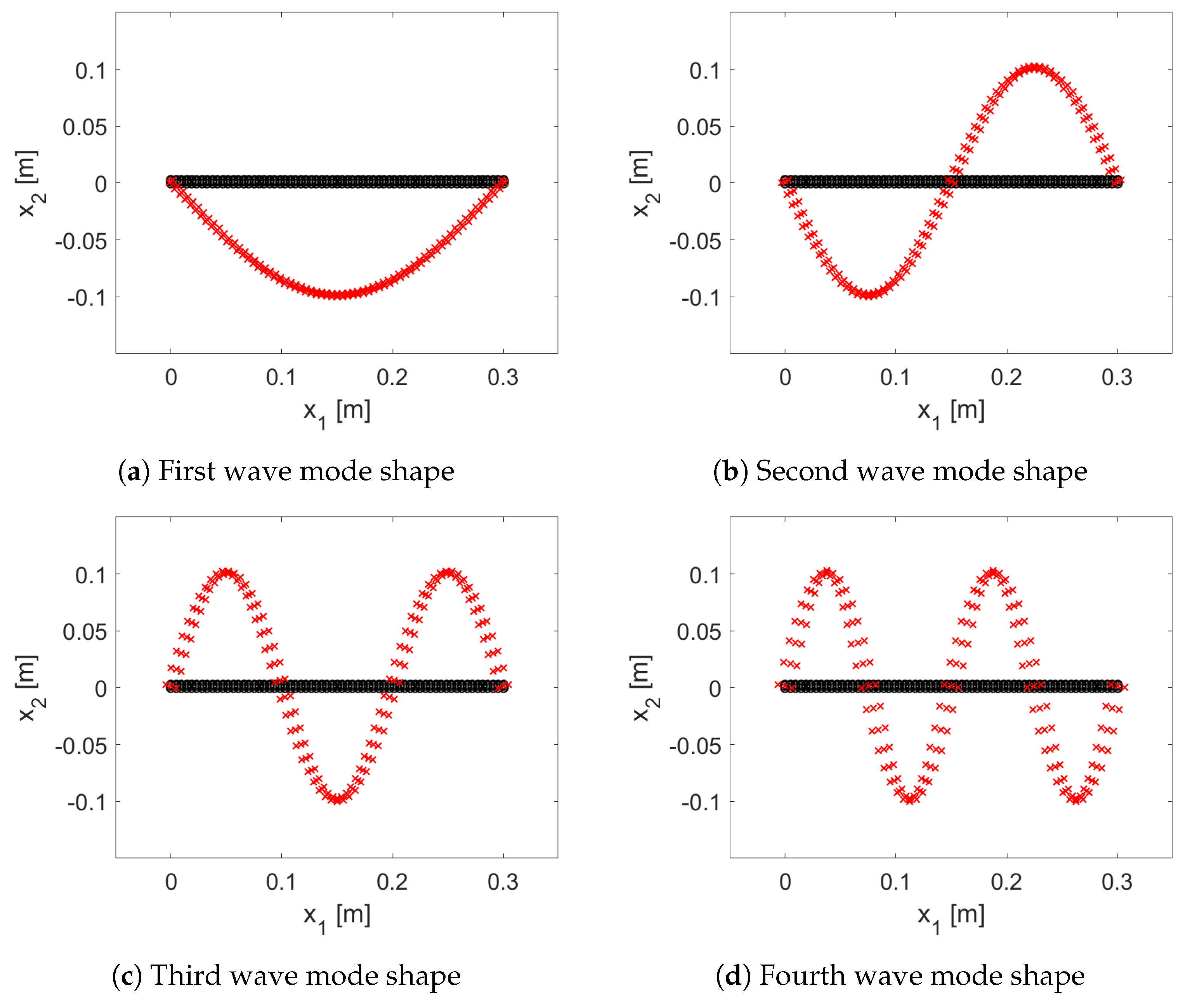
Finally, as an example, the first four wave mode shapes for the simply supported plate strip at about a frequency step of their cut-off frequencies are shown in
Figure 6.
5.2. SAFE Model of a More Complex-Shaped Waveguide
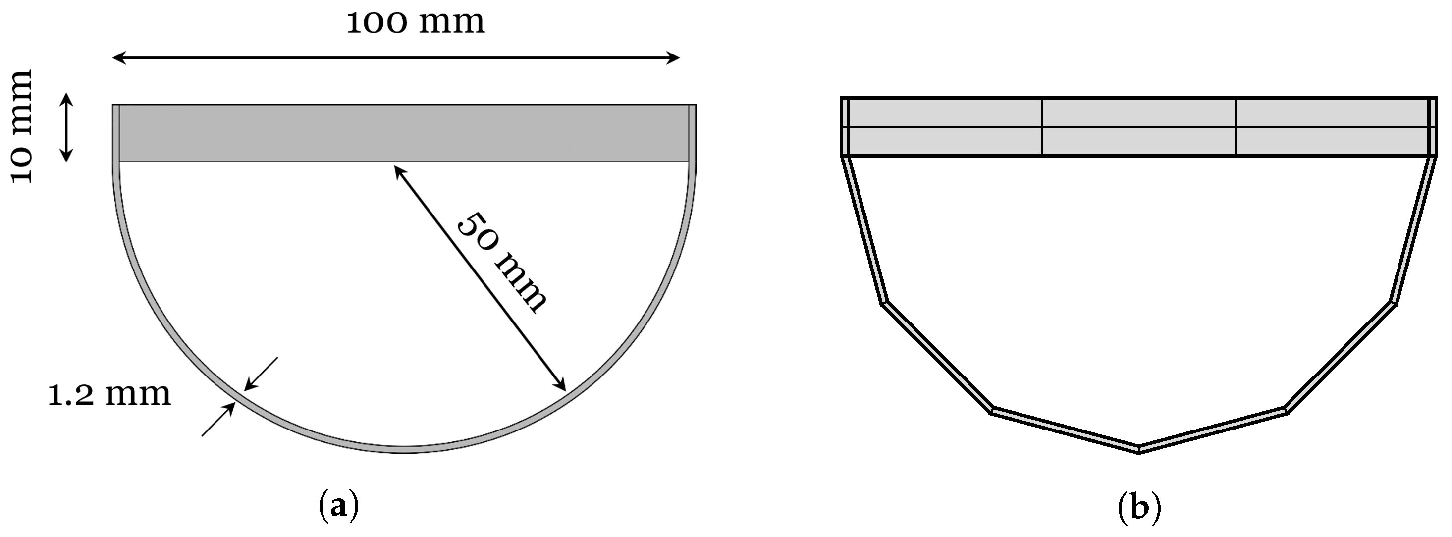
In the following, a SAFE model of a more complex-shaped waveguide is presented, and both free and forced wave propagation are solved. In
Figure 7a and
Figure 7b, the geometry and mesh of the implemented model are shown, respectively. The waveguide, made of aluminium, has a cross-section composed of a rectangular plate 100 mm by 10 mm, and a half-round plate with a diameter of 100 mm and a skin thickness of 1.2 mm. No structural damping is assumed in the model and its material properties are
,
and
. The mesh,
Figure 7b, consists of 16 four-sided elements which use quadratic Lagrange shape functions, for a total of 88 nodes and 264 DOFs.
In this work, with the only intent of verifying the correct implementation of the forced response formulation, the structural response was validated against a conventional FE model. However, a more refined mesh and the corresponding experimental validation can be found in [
19].
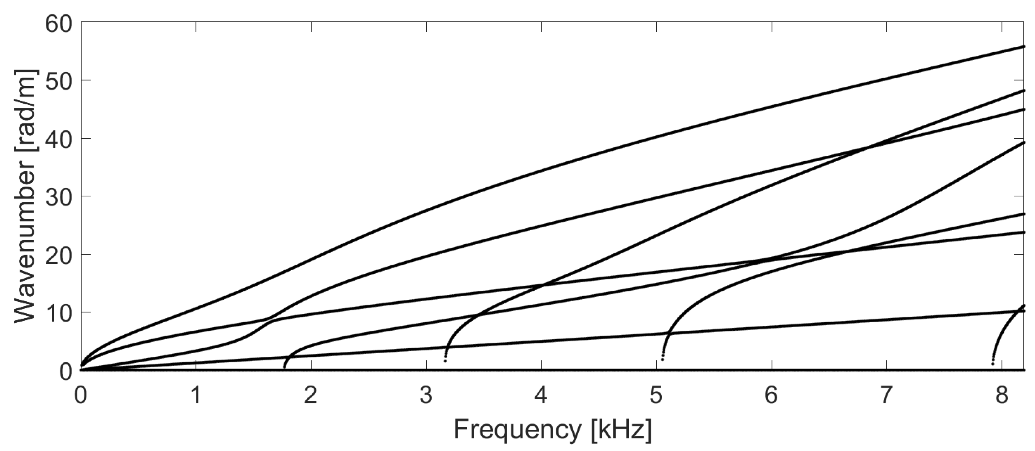
Shown in
Figure 8 are the dispersion curves of the propagating waves, in the form of wavenumber against frequency, obtained from the solutions of the eigenvalue problem of Equation (
16) for a set of frequencies from 0 to about 8 kHz and a frequency resolution of 4 Hz. It is worth highlighting that the chosen frequency bandwidth is purely arbitrary and thus does not represent a limitation of the method. As one can notice, within the chosen frequency range, the SAFE model predicts the presence of four zero-order wave modes, which propagate at all frequencies, and four higher-order wave modes, which cut off at about 2, 3, 5, and 8 kHz, respectively. The zero-order wave modes consist of two bending modes, a torsional and a compressional mode.
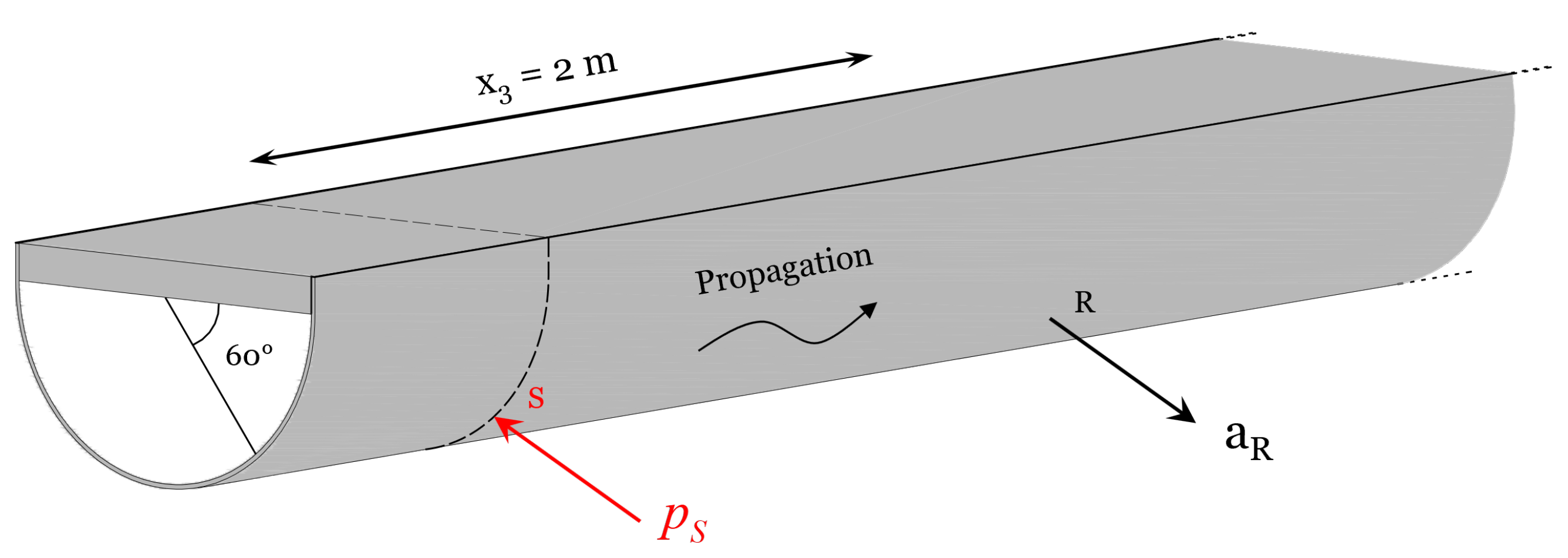
The SAFE model is then used to compute the forced response. Depicted in
Figure 9 is the source–receiver configuration used in the calculation; a concentrated load,
, is applied normally to the curved profile of the cross-section on point S, located at an angle of 60 degrees to the rectangular plate component. The acceleration response is detected at point R at a distance of 2 m from the applied load along the propagation path. For the sake of clarity, points S and R correspond to the same cross-section node of the SAFE mesh but in two different locations along the direction of propagation.
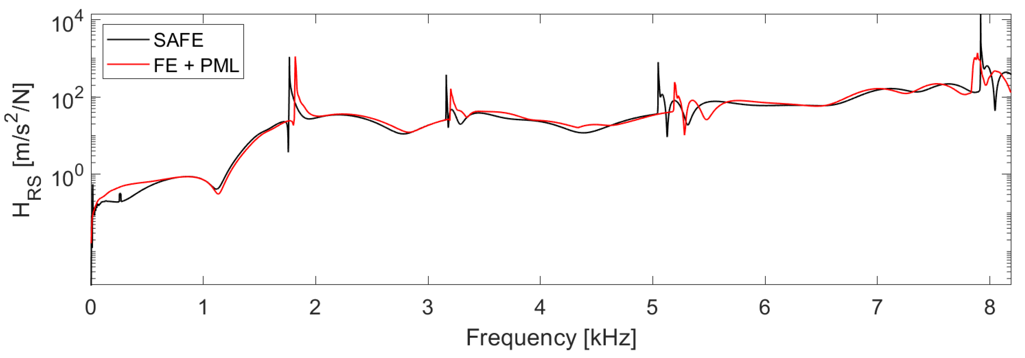
Figure 10 shows, in black, the magnitude of the transfer acceleration FRF obtained from Equation (
34). To verify the correct implementation of the forced response formulation, it is compared with the corresponding one, in red, obtained by a conventional FE model of the same waveguide implemented on COMSOL. The FE model has a length of 3 m to which a PML of 100 mm length has been added to the free terminations to cancel the contribution to the response of the reflected waves and thus make its results comparable to the SAFE ones. The PMLs and the waveguide have been discretised, respectively, with 5 and 240 finite elements along their length using the COMSOL “mapped” mesh and the quadratic Lagrange shape function.
As one can see, the magnitude presents high peaks at particular frequency values. These correspond to the cut-off frequencies of the higher-order waves, which start to propagate, respectively, at about 2 kHz, 3 kHz, 5 kHz, and 8 kHz. The high response peaks are due to the absence of damping in the model. In fact, at the cut-off frequencies, the new excited waves propagate with an infinite wavelength, and the whole structure resonates.
As simulations suggested, the discrepancies noticed in
Figure 10 are due to the reduced number of finite elements used to discretise the length of the FE model and the residual of reflecting waves not absorbed by the PMLs. The SAFE model was thus capable of predicting the transfer acceleration FRF with good accuracy, validating the presented forced response formulation. It is worth highlighting that the SAFE method requires less computational cost than the conventional FE approach, particularly for long waveguides such as pipes and rails. It also does not require the use of PMLs to avoid the contamination of reflected waves on the structural response.
6. Conclusions
In this paper, by using the FE software COMSOL Multiphysics and its “Livelink for Matlab” tool, a SAFE method implementation for free and forced wave propagation was proposed. Compared to a previous SAFE method implementation on COMSOL for the computation of the dispersion curves, the proposed approach enables the extraction from COMSOL of the assembled mass and stiffness SAFE matrices in the form of Matlab variables. This allows the prediction of free and forced wave propagation in Matlab, resulting in customised software that takes advantage of both the potential of commercial FE software and the power of Matlab without worrying about compatibility issues.
After describing the extraction procedure of the SAFE matrices from COMSOL, the implementation of free and forced wave propagation was presented. Two numerical examples were then introduced and used to validate the proposed SAFE modelling implementation. A simply supported plate strip of known dispersion relationships was first modelled and used to validate the SAFE matrix extraction procedure. Cut-off frequencies and dispersion curves were computed and compared with the corresponding analytical solutions, showing excellent agreement. A few examples of wave mode shapes were also presented. Successively, a waveguide model with a more complex geometry was implemented, and its dispersion curves of propagating waves were computed. To verify the correct implementation of the forced response formulation, an example of transfer acceleration FRF was computed and compared with the corresponding one obtained by a conventional FE model of the same structure implemented in COMSOL. To make the results comparable, a PML has been added to the free terminations of the FE model to minimise the contribution to the response of the reflected waves. The SAFE model could predict the transfer acceleration FRF with good accuracy, validating the forced response formulation. In principle, the presented method could be extended to predicting the forced response of homogeneous structures with discontinuities.
