Article

Effectiveness of the Seesaw System as a Means of Seismic Upgrading in Older, Non-Ductile Reinforced Concrete Buildings

by
Panagiota S. Katsimpini
and
George A. Papagiannopoulos
*
Laboratory of Structural Technology and Applied Mechanics, Hellenic Open University, 26335 Patras, Greece
*
Author to whom correspondence should be addressed.
Vibration 2023, 6(1), 102-112; https://doi.org/10.3390/vibration6010008
Submission received: 16 November 2022 / Revised: 5 January 2023 / Accepted: 19 January 2023 / Published: 21 January 2023
(This article belongs to the Special Issue Feature Papers in Vibration)

Abstract

:
This work investigates and discusses the effectiveness of the seesaw system when installed in an older, non-ductile reinforced concrete (RC) building for seismic upgrading purposes. In particular, two different configurations of the seesaw system are assumed in a two-storey 3D RC framed building which was designed according to older seismic provisions and, thus, is susceptible to flexural and shear failures. To check if there is any merit in employing the seesaw system in this RC building, non-linear time-history (NLTH) analyses are conducting using 11 seismic motions. Peak values for inter-story drift ratios (IDR), residual inter-story drift ratios (RIDR) and floor accelerations (FA) are computed, and the sequence and cause (i.e., due to surpass of flexural or shear strength) of plastic hinge formations are monitored. Leaving aside any issues related to fabrication and cost, interpretation of the results obtained by the aforementioned seismic response indices for the RC building under study leads to the conclusion that the seesaw system can be a retrofitting scheme for the seismic upgrading of older, non-ductile RC framed buildings.

1. Introduction

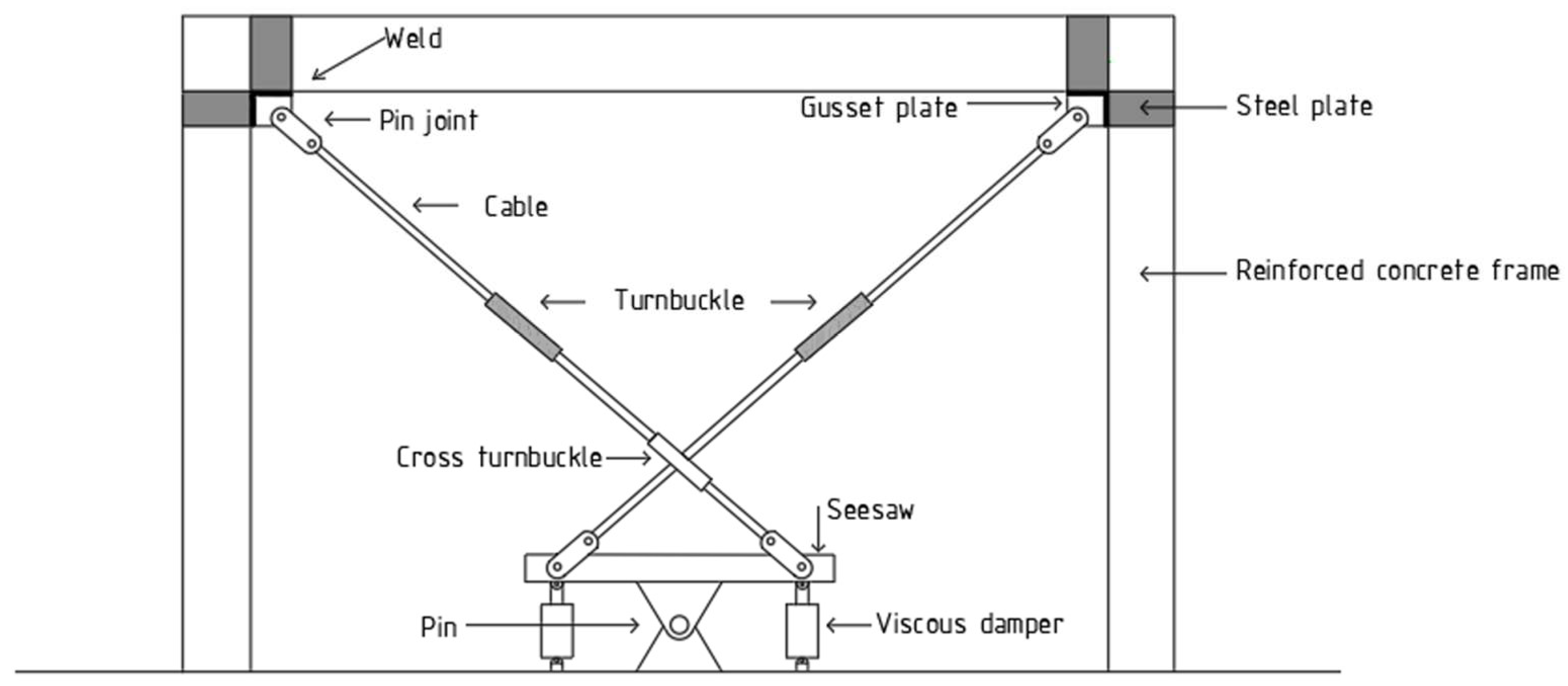
The seesaw system, originally proposed by Kang and Tagawa [1,2] and subsequently vastly improved by Katsimpini et al. [3,4] and Beskos et al. [5], consists of a pin-supported steel seesaw, two spiral strand ropes (cables) with turnbuckles that intersect from the edges of the seesaw and a couple of viscous dampers installed vertically on the seesaw (Figure 1). Up until now, the application of the seesaw system has been restricted to steel structures [1,2,3,4,5]. Presented in this paper is, for the first time in the literature, the application of the seesaw system to older, non-ductile reinforced concrete (RC) buildings as a means of their seismic upgrading.
Figure 1 displays the installation of the seesaw system within a typical RC frame. In particular, the seesaw and the dampers are connected using steel base plates, anchors and welds on the RC slab, whereas a gusset plate is used to connect the terminal edge of the cable (pin joint) with the beam-to-column interface. To enhance the flexural and shear capacity of the beam-to-column region, steel plates (or sheets) are wrapped (using injected epoxy adhesive and bolts if needed) around the beam and column, thus providing the necessary backing parts needed to weld the gusset plate. The horizontal (on the beam) and vertical (on the column) dimensions of the steel sheets are determined by the dimensions of the RC joint, but they are also controlled by the failure modes of the gusset plate [6]. Variations of the seesaw system regarding its installation type, the kind of dampers and the details of the connections may also be considered [1,2,3,4,5]. Nevertheless, in order to draw preliminary conclusions regarding the effectiveness of the seesaw system towards the seismic upgrading of non-ductile RC buildings, the installation type shown in Figure 1 is the starting one. It is recalled [3,4,5] that the seesaw system works only in tension, although a small prestressing of the cables in needed in order to ensure activation of both cables under the reversals of seismic motion. It should also be noted that the RC slab has to be checked against the effect of punching shear due to the forces transmitted by the dampers and the vertical pinned member of the seesaw.
To investigate the effectiveness of the seesaw system towards the seismic upgrading of non-ductile RC buildings, a two-storey 3D RC framed building designed according to older seismic provisions [7,8] and, thus, susceptible to flexural and shear failures, is examined herein. For such older, non-ductile RC buildings, one anticipates shear failure to override the flexural one in the critical (most stressed) regions of the RC members.
Two different configurations of the seesaw system to the two-storey RC framed building under study are possible: the concentric per floor installation, as shown in Figure 1, and the eccentric; i.e., the seesaw is eccentrically placed with respect to the RC frame, whereas the cables of the seesaw pass through properly detailed (attached to steel plates) deviators on the intersected floor beam (as shown in Figure 2) [9,10]. In both configuration cases of Figure 1 and Figure 2, the connection of the seesaw system with the ground is performed either by an isolated footing that has to be constructed, or directly to the existent foundation. Possible interaction of the seesaw system with the ground have to be studied; nevertheless, for the purposes of the present work, this interaction is assumed to be small.
The seismic behaviour of the two-storey RC building equipped with the seesaw system is assessed by means of non-linear time-history (NLTH) analyses employing a set of 11 seismic motions (accelerograms) recorded during historical earthquakes. The seismic response indices selected in order to evaluate the effectiveness of the seesaw system are the peak values for inter-storey drift ratio (IDR), residual inter-storey drift ratio (RIDR) and floor acceleration (FA), as well as the sequence of plastic hinge formations and their cause (flexural, flexural/axial or shear failure, the latter essentially corresponding to brittle failure). An inspection of the results provided by the aforementioned seismic indices proves that the insertion of the seesaw system in older, non-ductile RC buildings as a means of their seismic upgrading can be an alternative to the commonly applied retrofitting schemes.

2. Seismic Analysis of a Two-Storey RC Building with Seesaw System

This section presents the RC building under study, the installation type and design of the seesaw system, as well as the seismic motions and modelling assumptions for the purposes of the NLTH analyses.

2.1. The Two-Storey RC Building and Seesaw System Installed

The symmetrical in floor plan and regular in height two-storey RC building equipped with the seesaw system is shown in Figure 3. Two different configurations of the seesaw system are considered (see Figure 1 and Figure 2). According to Figure 3a, the seesaw system (its cables are highlighted by a green colour) is installed at the middle bay of the perimeter frames and at every floor. The seesaw system is concentrically placed with the respect to the frame where it is installed. The cables emanating from the seesaw are anchored at both ends of the beam of the middle bay. Thus, at each floor of the RC building, four seesaw systems are totally installed.
Referring now to Figure 3b, four seesaw systems eccentrically placed with respect to the middle bay of the RC frames of the perimeter are totally installed. Unlike steel members, where slotted holes can be easily fabricated in order to let the cables pass through them [5], this is not an option for the RC members. The seesaw systems are anchored at the outer ends of the beams of the second floor and deviators are used on the intersected beams of the first floor in order to let the cables of the seesaw pass through them [9,10]. The perimeter installation of the seesaw systems for the RC buildings shown in Figure 3 has been deliberately chosen in order to preclude any undesirable torsional effects (due to stiffness and mass distributions), beyond those simulated by means of accidental eccentricity.
For the two-storey RC building shown in Figure 3, each bay has a 6.0 m span and each storey has a 3.0 m height. Dead (excluding self-weight of the RC) and live loads on the slabs are assumed to be 1.5 kN/m2 and 2.0 kN/m2, respectively, whereas the thickness of the slab is 12 cm. The grade of concrete and steel reinforcement is C12/15 and S400 (fy = 400 MPa), respectively. The dimensions, as well as the steel reinforcement of the RC columns and beams, are presented in Table 1. The dimensions of all columns of the perimeter frames are 40/40, whereas those of the internal columns are 35/35. The dimensions of all beams are 20/40. The two-storey RC building is assumed to be fixed-base, i.e., soil-structure interaction is absent.
It is then assumed that the two-storey RC building must resist the seismic load that corresponds to the design spectrum of EC8 [11] for peak ground acceleration (PGA) equal to 0.24 g, soil class B, importance factor γ = 1.0 and behaviour factor q = 1.5. Therefore, response spectrum analysis is conducted and the storey shears in both horizontal directions of the building are computed. These storey shears are then utilised to estimate the diameter (section) of the cables of the seesaw system. The diameter and the design breaking (tensile) strength of the cables are presented in Table 2. In that table, the numbering of storeys starts from bottom to top.
It should be noted that, in the response spectrum analyses, a small initial pre-stressing (2.0 kN) has been taken into account for the cables. It is also assumed that the anchorage type (terminal edge) of the cables is such that the breaking (tensile) strength values of Table 2 do not need to be reduced according to [12]. Regarding the rest members of the seesaw (Figure 1 and Figure 2), the following assumptions are made: the damping coefficient of the linear viscous dampers is 250 kNs/m [13], the height of the rigid vertical steel plate (limited by the mid-stroke length of the dampers [13]) is 870 mm, and the length of the rigid horizontal steel plate is 1600 mm. The steel grade of the seesaw members is S275.

2.2. Seismic Motions and Modelling for NLTH Analyses

The two-storey RC buildings of Figure 3 are subjected to the two horizontal components of the 11 seismic motions (accelerograms) presented in Table 3. These accelerograms have been selected so that their 5%-damped response spectrum closely matches the aforementioned design spectrum of EC8 [11] in the 0.2 T–2.0 T period range, where T is the predominant period of the RC buildings. For the purposes of the seismic analyses, these seismic motions are assumed to be applied in the direction of the two orthogonal structural axes of the RC buildings of Figure 3, considering three values for the horizontal angle of seismic incidence, i.e., 0°, 45° and 90°, with respect to the geometric centre of the column layout. Some details about these accelerograms, i.e., the earthquake location, date and moment magnitude Mw, as well as the recording station and soil type, can be found in Table 3. Regarding soil type, the abbreviations HR, SR and SL stand for hard rock, sedimentary and conglomerate rock, and soil/alluvium, respectively.
The seismic response of the RC buildings shown in Figure 3 is determined through NLTH analysis involving both material and geometrical nonlinearities [14]. The innate viscous damping of the RC building is assumed to be 5% and follows the Rayleigh formula [14]. The floor slabs are modelled using thin shell elements. Beam and column members are modelled using standard frame elements, and their inelastic behaviour is taken into account using point plastic hinges at both their ends. An effective (cracked) stiffness for beams, columns and slabs is employed following [15]. The formation of plastic hinges takes place due to uniaxial bending in beams and due to the interaction between axial force and biaxial moment in columns [14,15]. Strength and stiffness deterioration phenomena are modelled according to [14,15].
Shear failure is also modelled using shear hinges placed next to the plastic hinges [14]. The maximum shear force that a shear hinge can sustain is determined by the relevant formulae of EC2 [16], which is simpler than the one in [15]. Therefore, when the shear force surpasses the force provided by this formula, shear failure occurs. On the basis of the steel reinforcement shown in Table 1, the maximum shear and moment capacities are 35 kN and 37 kNm, respectively, for beams; 76.3 kN and 122.1 kNm, respectively, for the 35/35 columns; and 93.5 kN and 150.3 kNm, respectively, for the 40/40 columns.
Since the RC buildings of Figure 3 do not possess or possess very limited ductility capacity, it is expected that shear failure (especially for columns) precedes flexural failure. The numerical acceptance criteria, i.e., hinge rotations, are those of [15]. The modelling of non-structural elements is omitted for reasons of future investigation.
Tension (cable) elements, rigid steel elements and discrete viscous dampers are used to model the seesaw system, and elastic behaviour for all elements of the seesaw system is considered. The viscous dampers possess zero stiffness and small mass, and their damping force depends on the velocity in a linear fashion. The properties of the viscous dampers, i.e., the damping coefficient and the mid-stroke length [13], are mentioned at the end of the previous section.
3. Seismic Response Results

The seismic response results of the RC buildings of Figure 3 equipped with the seesaw system, when subjected to the 11 seismic motions of Table 3, are presented in this section. In particular, these results involve peak values for IDR, RDIR and FA as well as the cause (due to flexure or shear) of plastic hinge formations, taking into account the angle of seismic incidence. Obviously, these peak values are computed only for those NLTH analyses that satisfy the numerical acceptance criteria of [15] and the exhibition of shear failures.
In NLTH analyses, the cases of considering plastic hinge formations from (i) flexure and shear and (ii) flexure, are distinguished, and the corresponding IDR, RDIR and FA results are presented separately. The reason behind this distinction is to highlight the difference in response indices if the increased flexural and shear strength of the critical regions (plastic hinges) offered by steel plates (or sheets) wrapped around the beam and column (see Figure 1 and Figure 2) is taken into account or not, shifting, thus, the mode of failure of these regions from flexural to shearing, respectively. The increased flexural and shear strength provided by properly designed steel plates is considered herein to be 1.5 times greater than the original flexural and shear strength values of beams and columns [17,18,19,20,21,22,23]. Due to the increased flexural and shear strengths, the curvature of the strengthened structural elements increases, leading essentially to a flexure-controlled behaviour of the plastic hinges.
For reasons of space, only the peak values of IDR, RIDR and FA as well as the number of failures (essentially corresponding to specific seismic motions-angle of seismic incidence combinations) for which either the numerical acceptance criteria [15] are not satisfied or shear failure occurs are tabulated. It should be noted that failure of the seesaw system, i.e., of the cables, dampers and members of the seesaw, is also checked by assuming elastic behaviour and the corresponding design strength values (from Table 2 for cables, 250 kN for the linear viscous dampers and the axial, shear and flexural strengths [24] for the seesaw members assuming S275 steel grade).
For reasons of expediency, in order to represent different earthquake levels and, consequently, to evaluate the effectiveness of the seesaw system for different earthquake levels, the seismic motions of Table 3 have been also descaled 0.5 and 0.25 times following [25] and the corresponding peak IDR, RIDR and FA values are also tabulated. The total number of NLTH analyses performed for each RC building of Figure 3 is 99, i.e., 11 (number of seismic motions) multiplied by 3 (values considered for the horizontal angle of seismic incidence) multiplied by 3 (earthquake levels corresponding to scaling factors 0.25, 0.5 and 1.0).

3.1. RC Building with Concentric Installation of the Seesaw System

The RC building of Figure 3a, i.e., equipped with concentrically placed seesaw systems with respect to the middle bay of the perimeter RC frames, exhibits shear failures to columns and beams for case (i) and flexural failures mainly to columns for case (ii). The number of failures, as well as the peak values found for IDR, RIDR and FA for cases (i) and (ii) and the three earthquake levels considered, are shown in Table 4 and Table 5, respectively. No failure of the viscous dampers, cables and seesaw members is attested. The fundamental period of the RC building of Figure 3a is 0.178 s.

3.2. RC Building with Eccentric Installation of the Seesaw System

The RC building of Figure 3b, i.e., equipped with eccentrically placed seesaw systems with respect to the perimeter RC frames, exhibits shear failures to columns and beams for case (i) and flexural failures mainly to columns for case (ii). The number of failures, as well as the peak values found for IDR, RIDR and FA for cases (i) and (ii) and the three earthquake levels considered, are shown in Table 6 and Table 7, respectively. No failure of the viscous dampers, cables and seesaw members is attested. The fundamental period of the RC building of Figure 3b is 0.177 s.

4. Discussion

A comparison between the number of failures shown in Table 4 and Table 5 reveals that the increased flexural and shear strength provided by the use of steel plates (case ii) improves the seismic behaviour of the RC building if the 100% earthquake level is considered, but does not lead to an improvement for the 25% and 50% earthquake levels. The same trend is witnessed if a similar comparison is performed between the number of failures shown in Table 6 and Table 7. However, it is expected that the number of failures for case ii) will be smaller if a larger increase of flexural and shear strength is achieved.
A comparison between the peak values for IDR, RIDR and FA in Table 4 and Table 5 and for the same earthquake level reveals an increase or equal values with the only exception the peak FA value for the 25% earthquake level. A comparison between the peak values for IDR, RIDR and FA in Table 6 and Table 7, and for the same earthquake level, reveals an increase in all three earthquake levels. As expected, peak values for IDR, RIDR and FA for case (ii) increase with increasing earthquake level. In terms of drift and residual drift capacity, the eccentric installation leads to higher peak IDR and RIDR values in comparison to the concentric one, but this is not accompanied by a smaller number of failures.
To verify if there is any merit in placing the seesaw system either in a concentric or in an eccentric way to the RC building under study, NLTH analyses of the RC building without the seesaw system are performed considering the three earthquake levels in conjunction with cases (i) and (ii). Peak values of IDR, RDIR, FA as well as the number of failures for the RC building without the seesaw system are presented in Table 8 and Table 9. The fundamental period of the RC building without the seesaw system is 0.208 s. Therefore, the insertion of the seesaw system adjusts only slightly the fundamental period which has been reported above to be approximately 0.18 s for both the RC buildings of Figure 3.
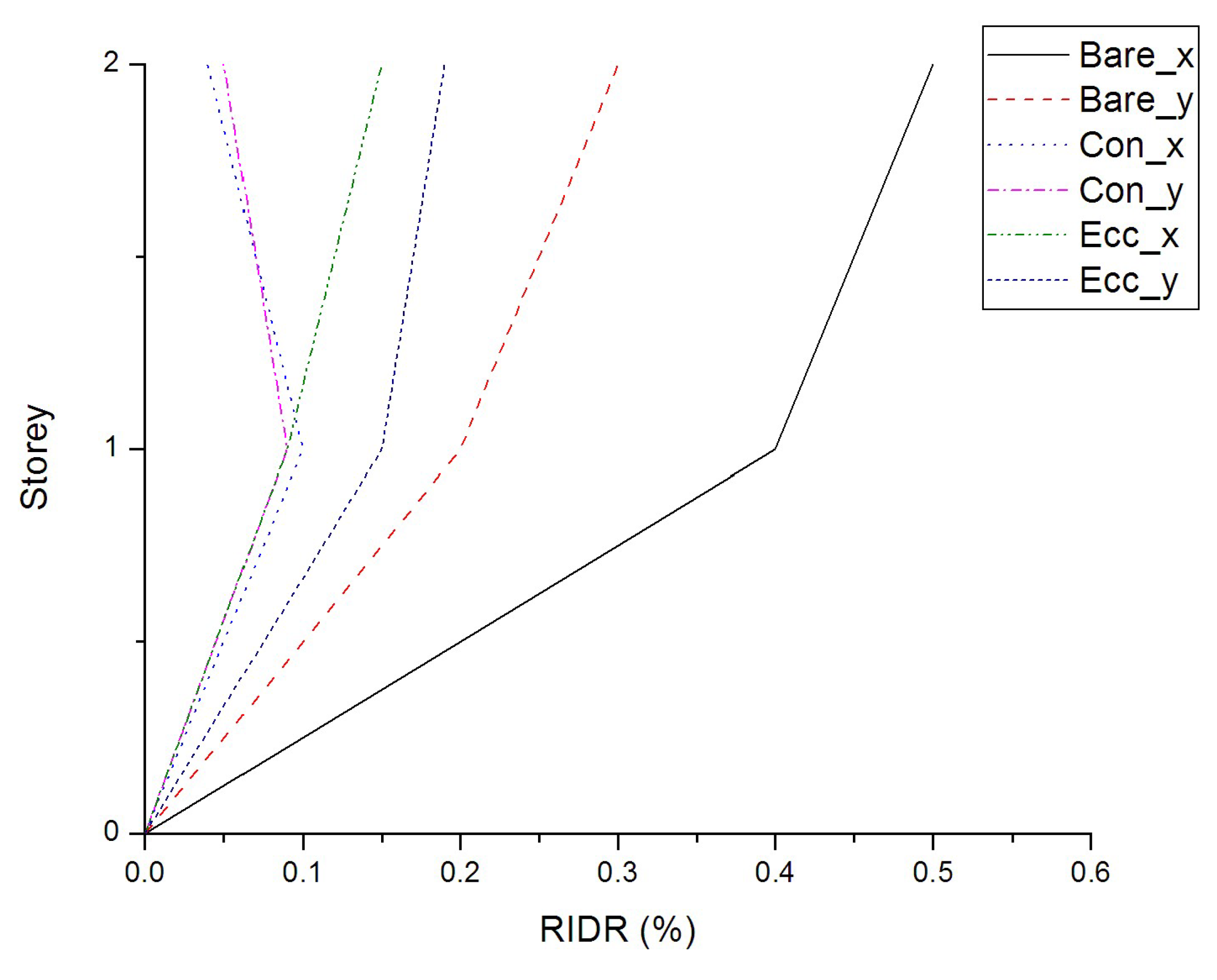
Figure 4, Figure 5 and Figure 6 present the storey peak IDR, RIDR and FA values for the seismic motion No. 4 of Table 3, which was found that induces the maximum responses. In these figures, the abbreviations ‘Bare’, ‘Con’ and ‘Ecc’ stand for the cases of the RC building without, with concentric and with eccentric seesaw system, respectively, whereas ‘x’ and ‘y’ denote the horizontal directions of the RC building. After an inspection of the plots shown in Figure 4, Figure 5 and Figure 6, one realises that the insertion of the seesaw system effectively reduces the peak IDR and RIDR values of the RC building, but not necessarily its peak FA values.
A comparison between Table 4 and Table 9 reveals that the seesaw system effectively reduces the peak IDR, RIDR and FA values of the RC building for all earthquake levels. Nevertheless, the number of failures remains unchanged because it essentially depends on the flexural and shear strengths of beams and columns in the critical regions (plastic hinges). These strengths can be further increased by proper detailing of the steel plates. This increase in strengths, if modelled in an NLTH analysis, would improve the seismic behaviour of the RC beams and columns, leading in all likelihood to a lower number of failures for the RC building. In other words, the insertion of the seesaw system in an older, non-ductile RC building for seismic upgrading purposes should necessarily be accompanied by local interventions at beams and columns (steel jacketing using steel plates) in order to increase their flexural and shear strengths at the critical regions (plastic hinges).

5. Conclusions

Leaving aside any issues related to fabrication and cost, and focusing only on the results and discussion presented above for the RC building studied, it is believed that the seesaw system in conjunction with properly designed local steel jacketing may constitute an effective seismic upgrading scheme for similar older, non-ductile RC buildings, leading to: (i) a reduction of peak IDR and RIDR values that lie in the ranges of 56–89% and 60–95%, respectively; (ii) an increase or decrease in peak FA values by about 32%. The aforementioned percentages depend on the earthquake level considered and are outcomes of the RC building studied. Therefore, they should not be generalised until more numerical examples involving various RC buildings are performed.

Author Contributions

P.S.K. and G.A.P. have equally contributed to the conception, design and execution of this study. The final paper has been critically revised and accepted by all the authors. All authors have read and agreed to the published version of the manuscript.

Funding

This research received no external funding.

Data Availability Statement

Data are contained within the article.

Acknowledgments

This research project is co-financed by the Hellenic Open University and the Greek Ministry of Education and Religious Affairs (research project 80272).

Conflicts of Interest

The authors declare no conflict of interest.

References

  1. Kang, J.D.; Tagawa, H. Seismic performance of steel structures with seesaw energy dissipation systems using fluid viscous dampers. Eng. Struct. 2013, 56, 431–442. [Google Scholar] [CrossRef]
  2. Kang, J.D.; Tagawa, H. Experimental evaluation of dynamic characteristics of seesaw energy dissipation system for vibration control of structures. Earthq. Eng. Struct. Dyn. 2014, 43, 1889–1995. [Google Scholar] [CrossRef]
  3. Katsimpini, P.S.; Papagiannopoulos, G.A.; Sfakianakis, M.G. On the seismic response and damping capacity of low-rise plane steel frames with seesaw system. Soil Dyn. Earthq. Eng. 2018, 107, 407–416. [Google Scholar] [CrossRef]
  4. Katsimpini, P.S.; Papagiannopoulos, G.A.; Askouni, P.K.; Karabalis, D.L. Seismic response of low-rise 3-D steel structures equipped with the seesaw system. Soil Dyn. Earthq. Eng. 2020, 128, 105877. [Google Scholar] [CrossRef]
  5. Beskos, D.; Katsimpini, P.; Papagiannopoulos, G.; Karabalis, D.; Hatzigeorgiou, G. Seismic performance and design details of low-rise steel structures equipped with the seesaw system. In Proceedings of the 17th World Conference on Earthquake Engineering, Sendai, Japan, 27 September–2 October 2021. [Google Scholar]
  6. Roeder, C.W.; Lumpkin, E.J.; Lehman, D.E. Balanced design procedure for special concentrically braced frame connections. J. Constr. Steel Res. 2011, 67, 1760–1772. [Google Scholar] [CrossRef]
  7. Papagiannopoulos, G.A.; Hatzigeorgiou, G.D.; Beskos, D.E. An assessment of seismic hazard and risk in the islands of Cephalonia and Ithaca, Greece. Soil Dyn. Earthq. Eng. 2012, 32, 15–25. [Google Scholar] [CrossRef]
  8. Greek Code for Seismic Resistant Structures (Royal Decree: FEK 36/A/19.2.1959). 1959. Available online: http://www.episkeves2.civil.upatras.gr/wp-content/uploads/2015/12/%CE%91%CE%9D%CE%A4%CE%99%CE%A3%CE%95%CE%99%CE%A3%CE%9C%CE%99%CE%9A%CE%9F%CE%A3-%CE%9A%CE%91%CE%9D%CE%9F%CE%9D%CE%99%CE%A3%CE%9C%CE%9F%CE%A3-1959.pdf (accessed on 2 January 2022).
  9. Sorace, S.; Terenzi, G. The damped cable system for seismic protection of frame structures—Part I: General concepts, testing and modeling. Earthq. Eng. Struct. Dyn. 2012, 41, 915–928. [Google Scholar] [CrossRef]
  10. Sorace, S.; Terenzi, G. The damped cable system for seismic protection of frame structures—Part II: Design and application. Earthq. Eng. Struct. Dyn. 2012, 41, 929–947. [Google Scholar] [CrossRef]
  11. Eurocode 8; Design of Structures for Earthquake Resistance—Part 1: General Rules, Seismic Actions and Rules for Buildings. CEN: Brussels, Belgium, 2004.
  12. Eurocode 3; Design of Steel Structures—Part 1–11: Design of Structures and Tension Components. CEN: Brussels, Belgium, 2009.
  13. Fluid Viscous Dampers & Lock-Up Devices Clevis—Base Plate Configuration. Available online: https://www.taylordevices.com/custom/pdf/brochures/CLEVIS_BASEPLATE_STANDARD_2.0.pdf (accessed on 25 September 2022).
  14. Carr, A.J. Ruaumoko 3D: Programs for Inelastic Dynamic Analysis. Theory and User Guide to Associated Programs; Department of Civil Engineering, University of Canterbury: Christchurch, New Zealand, 2009. [Google Scholar]
  15. ASCE/SEI 41-17; Seismic Evaluation and Retrofit of Existing Buildings. American Society of Civil Engineers: Reston, VA, USA, 2017.
  16. Eurocode 2; Design of Concrete Structures—Part 1–1: General Rules and Rules for Buildings. CEN: Brussels, Belgium, 2004.
  17. Adhikary, B.B.; Mutsuyoshi, H.; Sano, M. Shear strengthening of reinforced concrete beams using steel plates bonded on beam web: Experiments and analysis. Constr. Build. Mater. 2000, 14, 237–244. [Google Scholar] [CrossRef]
  18. Barnes, R.A.; Baglin, P.S.; Mays, G.C.; Subedi, N.K. External steel plate systems for the shear strengthening of reinforced concrete beams. Eng. Struct. 2001, 23, 1161–1176. [Google Scholar] [CrossRef]
  19. Uy, B. Strength of reinforced concrete columns bonded with external steel plates. Mag. Concr. Res. 2002, 54, 61–76. [Google Scholar] [CrossRef]
  20. Griffith, M.C.; Wu, Y.F.; Oehlers, D.J. Behaviour of steel plated RC columns subject to lateral loading. Adv. Struct. Eng. 2005, 8, 333–347. [Google Scholar] [CrossRef]
  21. Barnes, R.A.; Mays, G.C. Strengthening of reinforced concrete beams in shear by the use of externally bonded steel plates: Part 2—Design guidelines. Constr. Build. Mater. 2006, 20, 403–411. [Google Scholar] [CrossRef]
  22. Adhikary, B.B.; Mutsuyoshi, H. Shear strengthening of RC beams with web-bonded continuous steel plates. Constr. Build. Mater. 2006, 20, 296–307. [Google Scholar] [CrossRef]
  23. Arslan, G.; Sevuk, F.; Ekiz, I. Steel plate contribution to load-carrying capacity of retrofitted RC beams. Constr. Build. Mater. 2008, 22, 143–153. [Google Scholar] [CrossRef]
  24. Eurocode 3; Design of Steel Structures–Part 1–1: General Rules and Rules for Buildings. CEN: Brussels, Belgium, 2009.
  25. NIST GCR 11-917-15; Selecting and Scaling Earthquake Ground Motions for Performing Response-History Analyses. National Institute of Standards and Technology: Gaithersburg, MD, USA, 2011.
Figure 1. Installation and connection details of a seesaw system within an RC frame.
Vibration 06 00008 g001
Figure 2. Installation and connection details of a seesaw system eccentrically placed with respect to an RC frame.
Vibration 06 00008 g002
Figure 3. Concentric (a) and eccentric (b) installation of the seesaw system in the two-storey RC building.
Vibration 06 00008 g003
Figure 4. Distribution of peak IDR for the RC building with and without the seesaw system, when subjected to seismic motion No. 4 of Table 3.
Vibration 06 00008 g004
Figure 5. Distribution of peak RIDR for the RC building with and without the seesaw system, subjected to seismic motion No. 4 of Table 3.
Vibration 06 00008 g005
Figure 6. Distribution of peak FA for the RC building with and without the seesaw system, subjected to seismic motion No. 4 of Table 3.
Vibration 06 00008 g006
Table 1. Sections and the steel reinforcement of the two-storey RC building.
Column dimensions (cm)35/35 and 40/40
Longitudinal reinforcement (mm)4Φ25
Stirrups (mm)Φ8/150
Beam dimensions (cm)20/40
Longitudinal reinforcement (mm)2Φ14 (up) and 2Φ14 (down)
Stirrups (mm)Φ8/150
Table 2. Diameter and breaking strength of cables.
Diameter (mm)Breaking Strength (kN)
Two-storey/storey 119.0212.0
Two-storey/storey 216.0149.0
Two-storey/eccentric configuration19.0212.0
Table 3. Seismic motions.
No.EarthquakeDateStationMwSoil
1Bam, Iran26 December 2003Bam6.5SL
2Cape Mendocino, USA25 April 1992Cape Mendocino6.9SR
3Darfield, New Zealand03 September 2010Greendale7.0SL
4Superstition Hills, USA24 November 1987Parachute Test Site6.5SL
5Kobe, Japan17 January 1995Takatori6.9SL
6Loma Prieta, USA17 October 1989Los Gatos7.0HR
7San Fernando, USA09 February 1971Pacoima Dam6.6HR
8Cape Mendocino, USA25 April 1992Petrolia6.9SR
9Vrancea, Romania30 August 1986INCERC7.3SL
10El Salvador, El Salvador13 January 2001Observatorio7.6SR
11El Salvador, El Salvador13 January 2001Observatorio7.6SR
Table 4. Number of failures and peak IDR, RDIR, FA values-case (i): flexural and shear hinges.
Earthquake Level (%)Number of FailuresIDR (%)RIDR (%)FA (g)
2518/330.050.0020.37
5024/330.070.020.36
10033/33---
Table 5. Number of failures and peak IDR, RDIR, FA values-case (ii): flexural hinges.
Earthquake Level (%)Number of FailuresIDR (%)RIDR (%)FA (g)
2518/330.050.0080.30
5024/330.080.020.53
10024/330.250.120.80
Table 6. Number of failures and peak IDR, RDIR, FA values-case (i): flexural and shear hinges.
Earthquake Level (%)Number of FailuresIDR (%)RIDR (%)FA (g)
2518/330.050.0040.32
5024/330.090.040.42
10033/33---
Table 7. Number of failures and peak IDR, RDIR, FA values-case (ii): flexural hinges.
Earthquake Level (%)Number of FailuresIDR (%)RIDR (%)FA (g)
2518/330.090.010.24
5024/330.170.050.50
10024/330.440.200.75
Table 8. Number of failures and peak IDR, RDIR, FA values (no seesaw, flexural and shear hinges).
Earthquake Level (%)Number of FailuresIDR (%)RIDR (%)FA (g)
2518/330.500.200.70
5024/330.900.160.50
10033/33---
Table 9. Number of failures and peak IDR, RDIR, FA values (no seesaw, flexural hinges).
Earthquake Level (%)Number of FailuresIDR (%)RIDR (%)FA (g)
2524/330.400.100.35
5024/330.700.400.40
10024/331.000.500.90
Disclaimer/Publisher’s Note: The statements, opinions and data contained in all publications are solely those of the individual author(s) and contributor(s) and not of MDPI and/or the editor(s). MDPI and/or the editor(s) disclaim responsibility for any injury to people or property resulting from any ideas, methods, instructions or products referred to in the content.