Article

Research on Impact Attenuation Characteristics of Greyhound Racing Track Padding for Injury Prevention

Faculty of Engineering and Information Technology, University of Technology Sydney, Sydney 2007, Australia
*
Author to whom correspondence should be addressed.
Vibration 2022, 5(3), 497-512; https://doi.org/10.3390/vibration5030028
Submission received: 16 June 2022 / Revised: 22 July 2022 / Accepted: 27 July 2022 / Published: 4 August 2022

Abstract

:
To reduce injuries to greyhounds caused by collisions with fixed racing track objects such as the outside fence or the catching pen structures, padding systems are widely adopted. However, there are currently neither recognised standards nor minimum performance thresholds for greyhound industry padding systems. This research is the first of its kind to investigate the impact attenuation characteristics of different padding systems for use within the greyhound racing industry for the enhanced safety and welfare of racing greyhounds. A standard head injury criterion (HIC) meter was used to examine padding impact attenuation performance based on the maximum g-force, HIC level and the HIC duration. Initially, greyhound racing speed was recorded and analysed with the IsoLynx system to understand the potential impact hazard to greyhounds during racing which indicates the necessity for injury prevention with padding. A laboratory test was subsequently conducted to compare the impact attenuation performance of different kinds of padding. Since padding impact attenuation characteristics are also affected by the installation and substrate, onsite testing was conducted to obtain the padding system impact attenuation performance in actual greyhound racing track applications. The test results confirm that the padding currently used within the greyhound industry is adequate for the fence but inadequate when used for rigid structural members such as the catching pen gate supports. Thus, increasing the padding thickness is strongly recommended if it is used at such locations. More importantly, it is also recommended that, after the installation of padding on the track, its impact attenuation characteristics be tested according to the methodology developed herein to verify the suitability for protecting greyhounds from injury.

1. Introduction

In many countries, including Australia, United Kingdom, Sweden, Denmark, Germany, Netherlands and New Zealand, greyhound racing is a popular sporting and recreational activity which has been conducted for more than a hundred years [1,2,3]. With increasing awareness of animal welfare, the injury and death of racing greyhounds has attracted public attention. As a result, we have sought to better understand what causes these injuries in order to reduce and prevent future serious injuries. Injuries to the greyhounds can be caused by several mechanisms [4,5,6]. Among these mechanisms are collisions with fixed objects such as the outside fence on a track bend or if the greyhounds fail to slow down after the completion of the race within the catching pen.
Most greyhound races are conducted at oval-shaped tracks where the radius of the bends and the camber on the bends are not standardised within the industry. For example, in Australia, the track radii of the bends vary from 49 m at Tamworth to 73 m at Mandurah. The transition between a radius bend and a straight results in the greyhounds being subjected to a high instantaneous jerk [7,8,9,10,11]. In addition, while navigating around a bend, greyhounds always experience centrifugal force which tends to pull them to the outside of the track. If greyhounds cannot handle this dynamic centrifugal force by adjusting their posture, trajectory and speed, they experience a motion that does not follow the path of the lure but leads to impact with the outside fence. If collision between greyhounds occurs, they can easily fall and slam into the outside fence [12]. This is more likely to occur when the greyhounds are at their maximum speed on a circuit that does not contain a 50 m or greater length transition path between the straight and the bend. The tighter the bend, the greater the centrifugal force and the greater the probability of the greyhound impacting the outside fence [13].
When the competitive component of the race comes to an end, the greyhounds decelerate rapidly between the finish post and the catching pen. This rapid change in speed needs to occur within the boundary distance condition such that all the greyhounds can perform this in a safe and efficient manner. Moreover, the greyhounds’ stopping needs to occur after they cross the run back gate, at which point it is closed and the lure is no longer visible to the greyhounds [14]. The distance to the catching pen from the point a greyhound begins to rapidly slow down varies depending on the catching pen location at each individual track. During the catching pen slowing down period, the greyhounds decrease their speed from almost full speed, which could be more than 15 to 0 m/s [15]. There is a residual risk that one or more greyhounds would not be able to reduce their speed adequately and would collide with a component of the catching pen infrastructure. These components include the catching pen gate, gate supporting column and the catching pen fence.
To protect the greyhounds from injuries caused by colliding with the fence, protective padding is widely applied on tracks. Unlike the padding for human-centred activities, which have rigorous and clear requirements and standards [16,17,18,19,20,21,22], the padding for greyhound racing tracks is usually selected intuitively. It was found that padding used by different tracks had various sizes, thicknesses, filling materials, surface materials and installation methods, which result in totally different impact attenuation performance [23]. The greyhound colliding pattern and padding characteristics have not been systematically researched or published in the literature. Thus, there has been no rigorously prepared and peer-reviewed information presented to date about the suitability of a certain padding specification for a particular track, the methodology to design the padding system based on the track shape, greyhound speed and expected collision patterns.
This research therefore aimed to conduct an initial, systematic investigation on greyhound racing track padding performance. Firstly, the speed of racing greyhounds was researched and analysed with their typical collision, with track-based fixed infrastructure such as fences and gates being assessed. The outcomes from this were used as the basis for determining which of the characteristics of the padding systems were to be analysed. Then, laboratory and on-site impact attenuation tests were conducted for different padding systems which are currently installed on greyhound racing tracks to record and analyse their impact attenuation characteristics with different applications and substrates. Finally, from the obtained analytical and experimental results, discussions and recommendations are made regarding the importance of selecting a proper padding system and of conducting impact attenuation checks in greyhound racing tracks after installation.

2. Greyhound Racing Impact and Padding Conditions

2.1. Greyhound Racing Speed

To establish the potential greyhound padding impact speed, the IsoLynx real-time location tracking system [24] was utilised to record the greyhound real-time path tracing during racing from the starting box to shortly after the finishing line. Greyhound speed could be thereafter calculated from the IsoLynx path tracing data. The data were collected at a greyhound racing track in Australia. The track plan is shown in Figure 1, which has four different racing distances ranging from 350 m to 500 m.
In Figure 1, the 350 m, 395 m, 450 m and 500 m labels represent the starting box locations for different racing distances where the finishing post is denoted by FP. All of the four race distance starts are located along the straight section of the track. Transition point 1 (TP1) denotes the end of the straight track path section; a 75 m long clothoidal transition commences at TP1 and ends at TP2. Between TP2 and TP3 there is a bend with a constant 70 m radius. There is another 51 m long clothoidal transition between TP3 and TP4, followed by a short 0.14 m straight between TP4 to TP5. Between TP5 and TP6, there is a 65 m-long clothoidal transition within which the finish point is located. After TP6, there is an 83 m-long bend with a constant 55 m radius bend which leads the greyhounds to the catching pen.
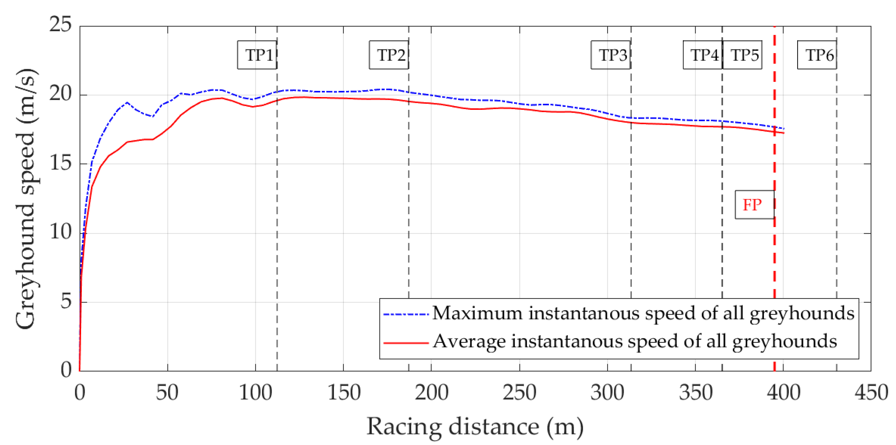
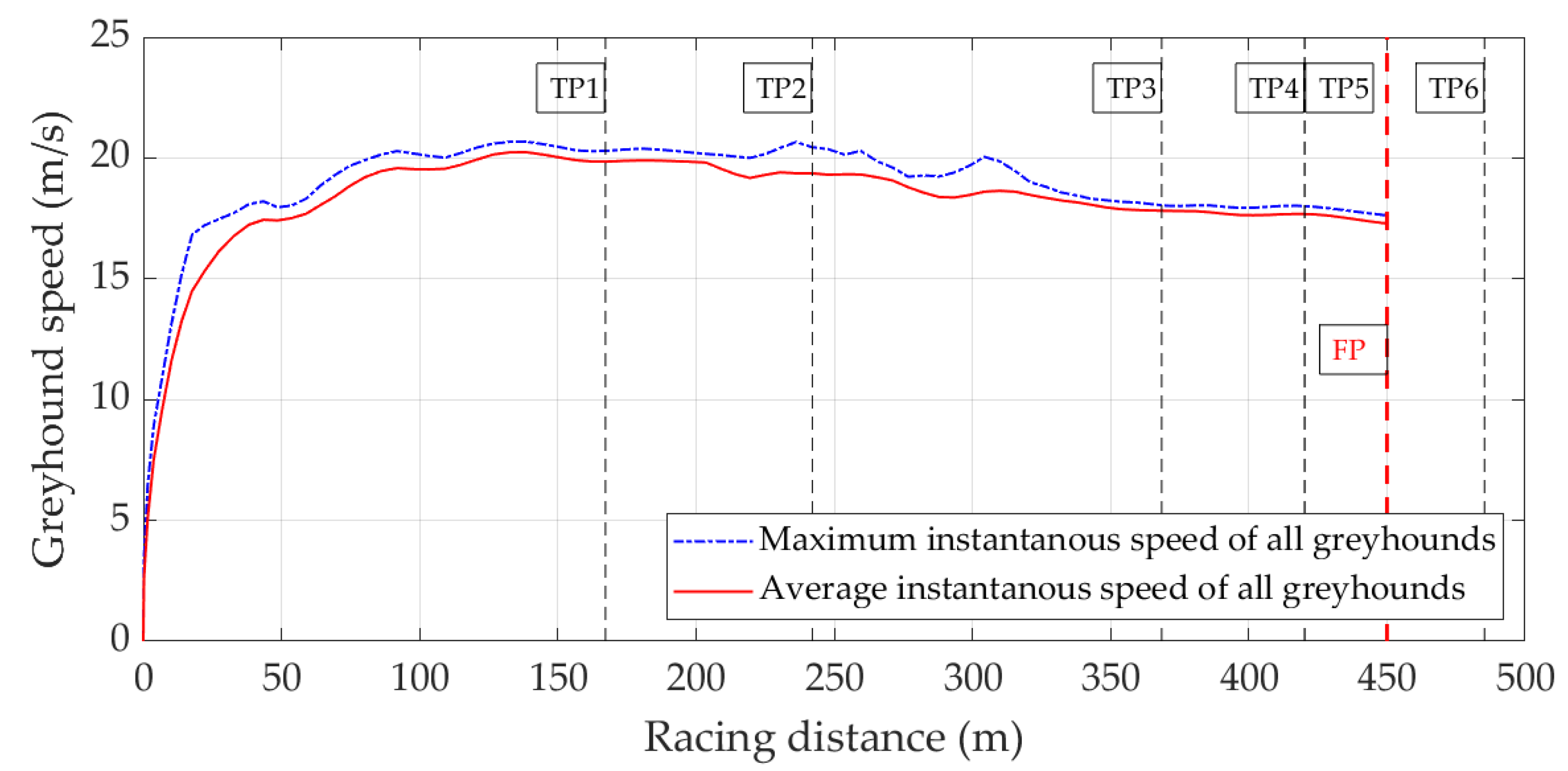
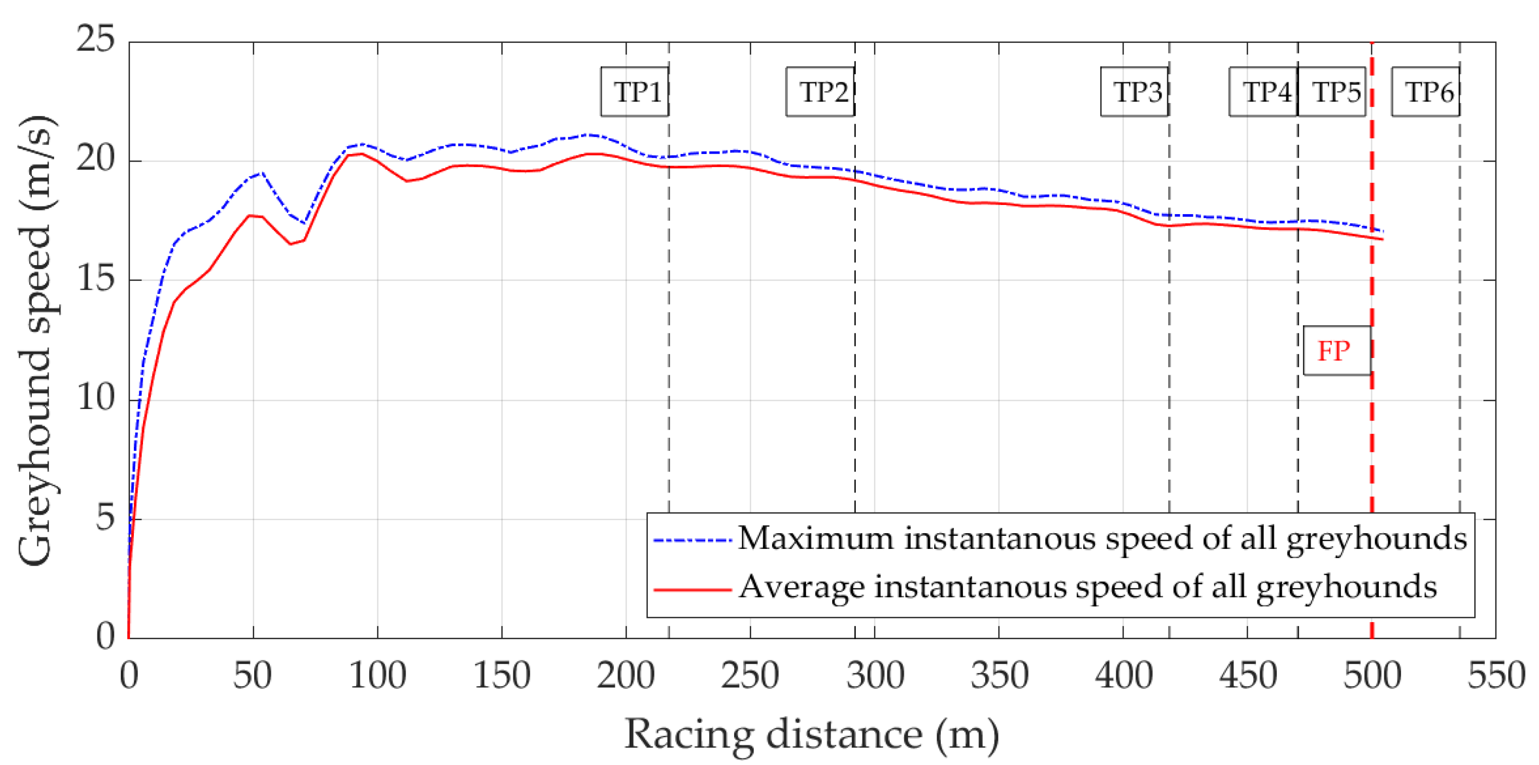
The maximum and average instantaneous greyhound speeds of different racing distances are shown in Figure 2, Figure 3, Figure 4 and Figure 5. The speed data in these figures are based on a number of greyhounds: 19 greyhounds for the 350 m racing distance; 16 for 395 m; 15 for 450 m; and 24 greyhounds for the 500 m race distance. For each racing distance, the instantaneous speeds of all the greyhounds were compared with the highest overall speed defined as the maximum instantaneous greyhound speed in the subsequent figures. This value indicated the largest potential impact speed along the entire race distance. The mean instantaneous speed for all greyhounds was also calculated, which helped to identify the normal speed of greyhounds throughout the entirety of the race.
From the greyhound speed profile, it was found that greyhounds, on average, require approximately 80 to 100 m to accelerate to their full speed—slightly above 20 m/s. For all racing distances, the greyhound racing track provides enough straight or small curvature transition paths for greyhounds to accelerate fully before they are subjected to any centrifugal force; this is confirmed by greyhounds reaching their maximum speed before TP2. This is an important factor in protecting greyhounds because if they accelerate into the bend, they have to handle both the centrifugal force and the force associated with their forward acceleration. However, if they are already running with their maximum speed before entering the bend, they only need to handle the centrifugal force [25]. The speed at TP2 is therefore taken as the greyhound speed when entering the bend, which should be considered when designing and testing the padding.
A possible collision between a greyhound and an impact attenuation pad can occur at any angle from almost glancing (0°) to perpendicular (90°), where the latter is the least favourable scenario. This is depicted in Figure 6, where the impact angle is not perpendicular and the greyhound is likely to rebound with a reduced angle (the ghost greyhound). The energy lost during an impact also substantially reduces the greyhound’s speed.

2.2. Greyhound Racing Track Padding

To protect the greyhounds from colliding with the fence, race tracks are usually padded on the outside fence on bends and in the catching pen. However, different padding materials and installation methods are used at different tracks without a consistent standard or guidelines. Figure 7 depicts different padding examples of various padding sizes, thicknesses, materials and installation methods at several greyhound racing tracks in Australia. The subsequent sections report results of the investigation of performance of some of these padding examples in the lab and at the track.

3. Laboratory Impact Attenuation Test of Different Padding

3.1. Head Injury Criterion (HIC) Definition and Application

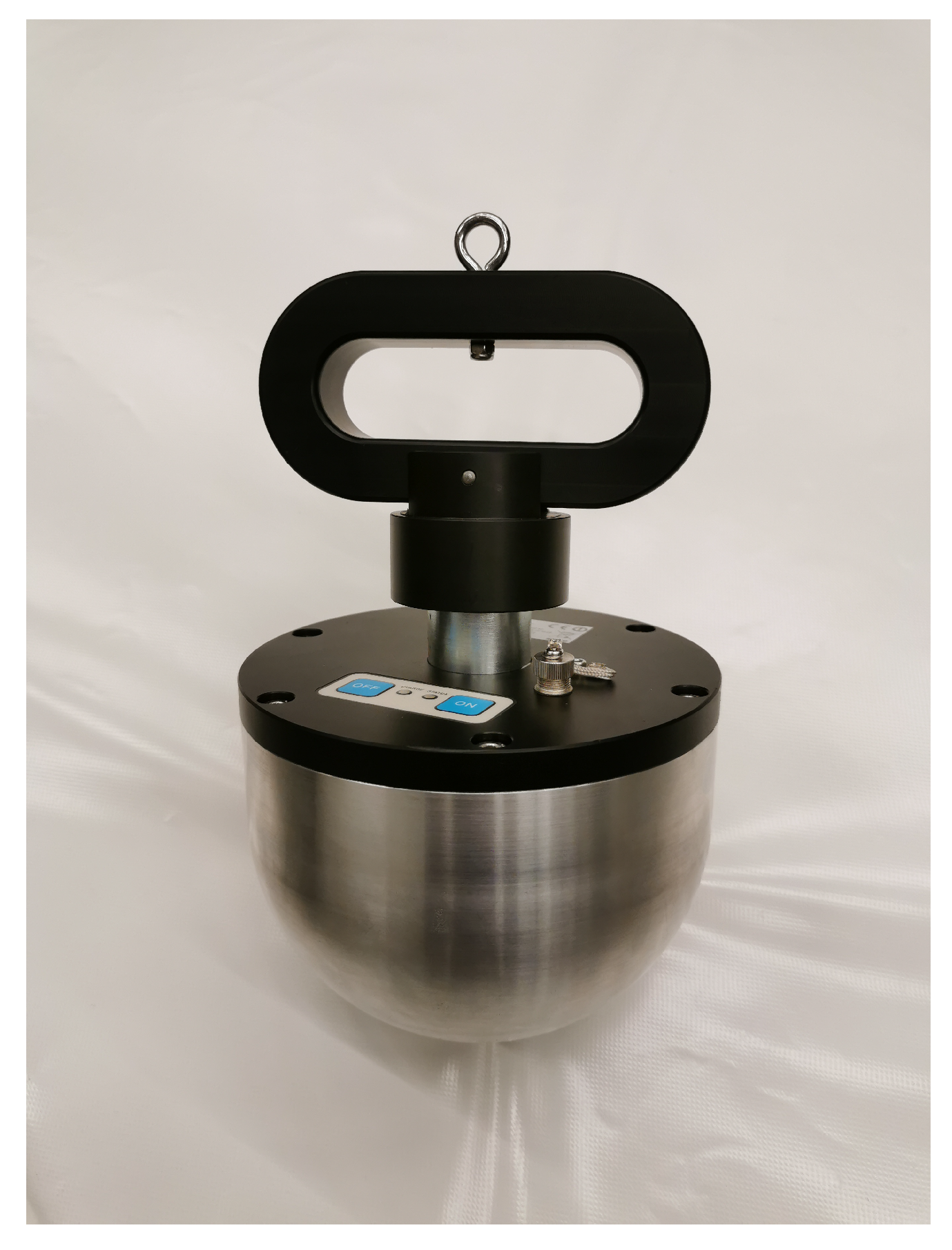
To investigate the impact attenuation performance of different padding systems, tests were conducted using the HIC impact test meter as shown in Figure 8. In the HIC meter, a triaxial accelerometer is positioned in the centroid of the semispherical headform. When the headform impacts with other objects, the accelerometer measures and records the headform accelerations from which the HIC is calculated in accordance with Equation (1) [26]:
HIC = ( t 2 t 1 ) 1 t 2 t 1 t 1 t 2 a ( t ) d t 2.5 m a x
where t 1 and t 2 are the initial time and final time of the HIC calculation period, while a ( t ) is the measured real-time acceleration during this period.
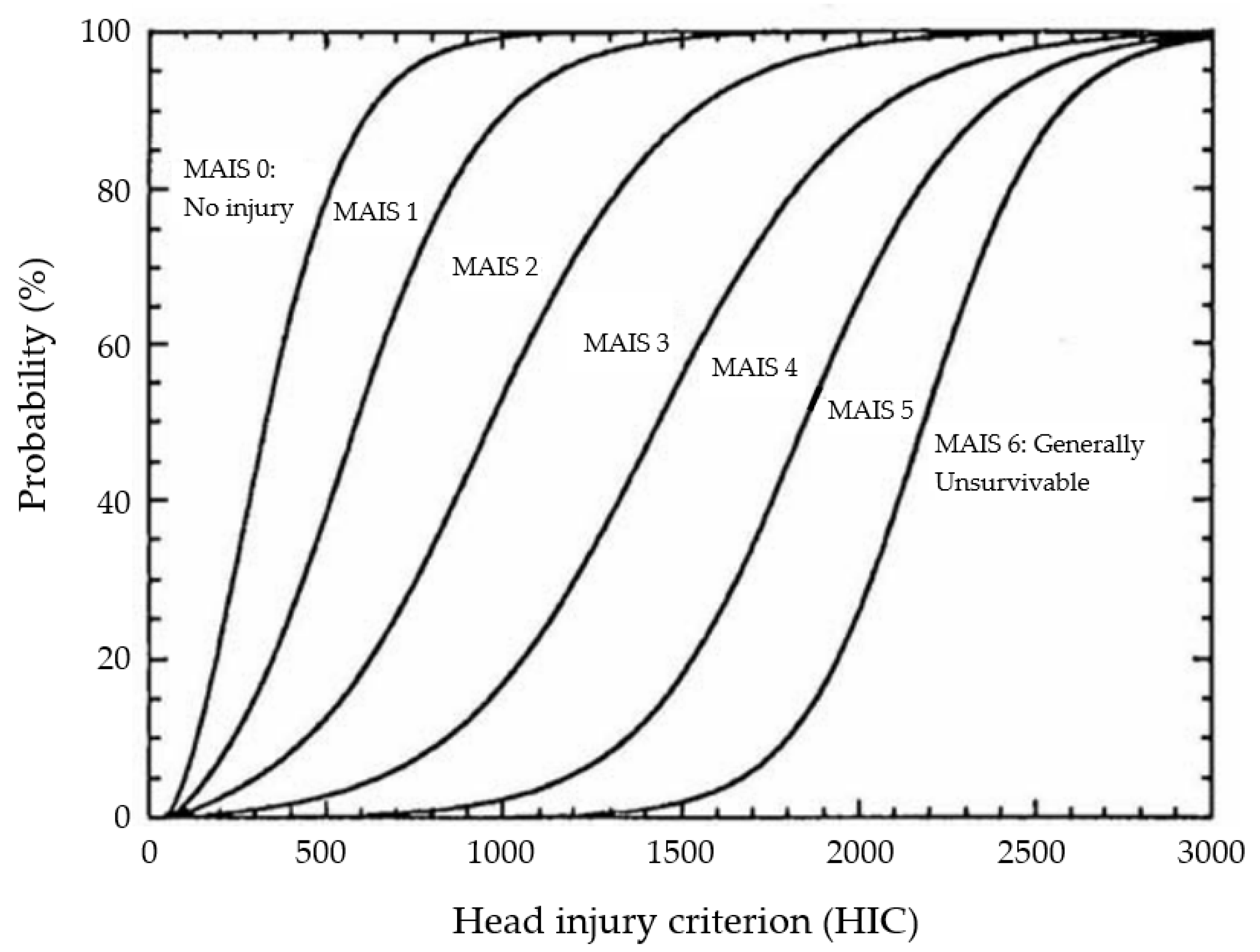
There is no known published research on the relationship of the severity of impacts on canines and the measured HIC and underlying accelerations. There is, however, considerable such research on the severity of impacts for humans [27,28]. The graph of probability of Maximum Abbreviated Injury Scale (MAIS) [29] for an average adult human male, shown in Figure 9, describes the probability of different levels of injury occurring for a certain HIC value. The graph is used in a number of performance standards both in Australia and around the world. In Australia, for example, it is used to limit the types of injuries children are exposed to within playgrounds [30].
The MAIS has a scale from 1 to 6, where:
  • Minor (e.g., superficial laceration).
  • Moderate (e.g., fractured sternum).
  • Serious (e.g., open fracture of humerus).
  • Severe (e.g., perforated trachea).
  • Critical (e.g., ruptured liver with tissue loss).
  • Maximum (e.g., total severance of aorta).
As can be seen in Figure 9, 1000 HIC indicates: a 3% probability of a critical head injury (MAIS 5); a 18% probability of a severe injury (MAIS 4); a 55% probability of a serious injury (MAIS 3); a 89% probability of a moderate injury (MAIS 2); and a 99.5% chance of a minor injury (MAIS 1).
According to the commonly used international impact attenuation standards for children’s playground equipment [31,32,33,34], to effectively avoid fatal impact of falling in playgrounds, the peak acceleration during an impact test must be less than 200 g, the HIC must be less than 1000 and the duration over which the HIC is calculated must be greater than 3 ms.
Figure 9. Prasad–Mertz probability curves of a specific injury for a specific HIC value [29,35].
Vibration 05 00028 g009

3.2. Laboratory Impact Attenuation Test

In this research, three different padding systems were tested in the laboratory as shown in Figure 10. The 75 mm-thick padding is already used on greyhound racing tracks, while the 50 mm and 85 mm-thick padding samples were tested for comparison. During the test, the padding samples were laid down on a concrete floor that provided a hard substrate. The HIC impact meter was dropped from different heights from directly above the centre of the padding. When the HIC impact meter contacted the padding after free fall, it obtained negative acceleration and ultimately stopped. The HIC and maximum acceleration were calculated and recorded during this process. For all three padding samples, tests were conducted with vinyl cover sealed and not sealed, respectively. The vinyl-cover-sealed case represents the normal use of the padding where an additional airbag effect might exist. The vinyl cover not sealed case removed the airbag effect, testing the foam/vinyl only and potentially representing a torn padding cover condition on the greyhound racing track.
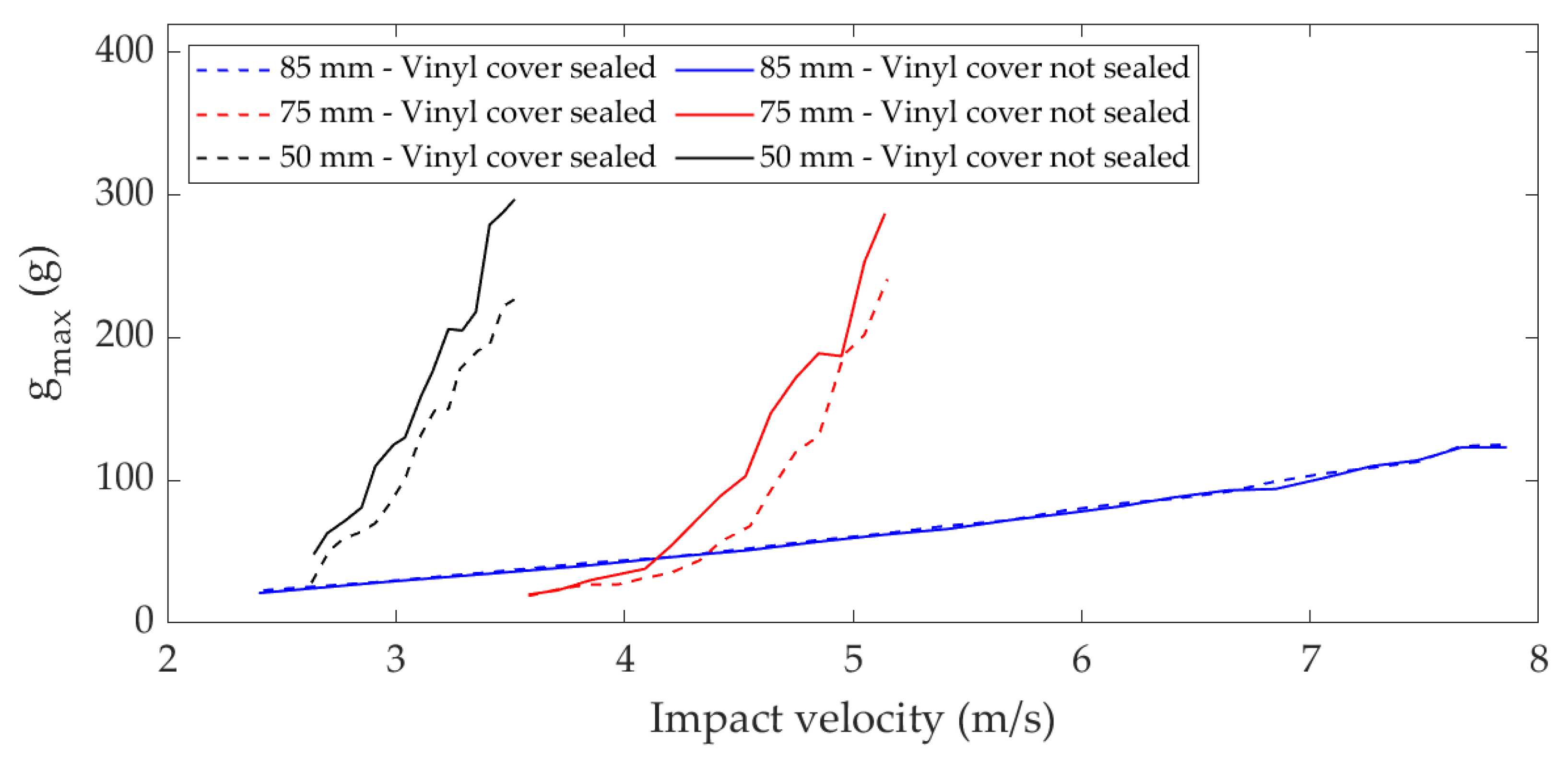
The 85 mm-thick padding was tested with HIC impact meter heights ranging from 0.3 m to 3.15 m with 0.15 m increments. The 75 mm-thick padding was tested with HIC meter heights ranging from 0.65 m to 1.35 m with 0.05 m increments. The 50 mm-thick padding was tested with HIC impact meter heights ranging from 0.35 m to 0.63 m with 0.02 m increments. The HIC impact meter maximum fall heights were determined by the HIC and maximum acceleration thresholds, which were to be less than 1000 and 200 g, respectively, as discussed. Tests were stopped when either the HIC or maximum acceleration reached their respective thresholds. During the testing, the impact positions were roamed on the padding to avoid continuously impacting the same position, which might cause padding fatigue and reduce padding performance.
The measured HIC and maximum acceleration observed during these laboratory impact attenuation tests are shown in Figure 11 and Figure 12. The results show that the 85 mm padding has the best impact attenuation performance. For the 75 mm padding and 50 mm padding, better impact attenuation performances were achieved with the vinyl cover sealed, confirming the airbag effect exists in these pads. In contrast, the 85 mm padding did not show an apparent airbag effect as little difference was observed in performance between the sealed and unsealed cases.

4. On-Site Impact Attenuation Test of Different Padding

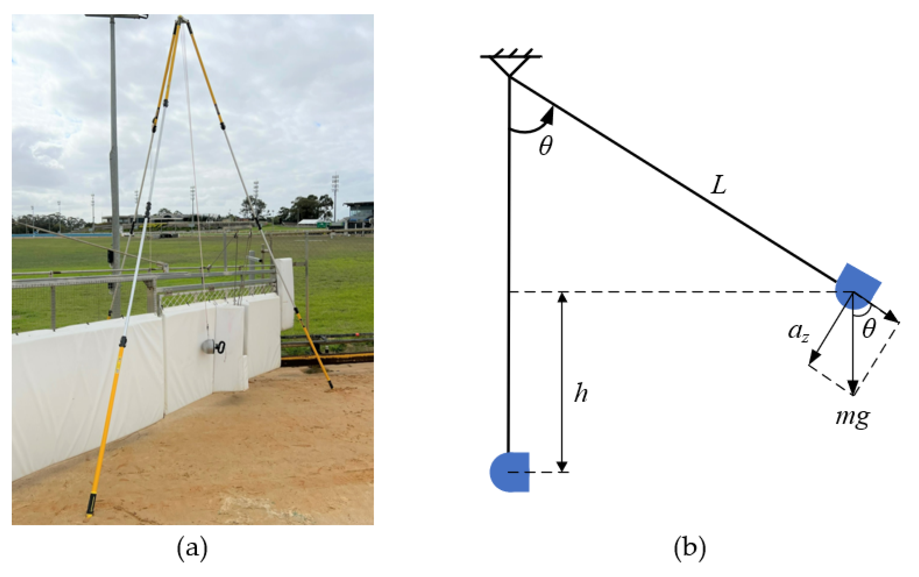
Padding systems are installed on greyhound racing tracks using different methods and with various alternative substrates in comparison with the rigid concrete floor testing in the laboratory. Therefore, on-site tests, as shown in Figure 13a, were conducted to better determine the padding impact attenuation performance when installed on the track. This testing reflected the actual in-situ greyhound racing track impact attenuation conditions. Since all the padding was installed perpendicular to the ground, the HIC impact meter had to impact the padding from the side like a pendulum. During the test, the HIC meter was hung from a tripod and released from a measured height. When released, it impacted the padding from the side which was analogous to the greyhound impact conditions.
The on-site test condition is depicted in Figure 13b. With the HIC meter lifted to a height of h above the impact location, its acceleration in the z-axis is:
a z = F z m = m g s i n θ m = g L 2 ( L h ) 2 L
where g is the gravitational acceleration 9.81 m/s 2 , L is length of the suspension rope, h is HIC meter height from its stationary position (HIC meter at lowest position and rope vertical) and θ is the angle of the rope corresponding to h height.
Ignoring the insignificant air resistance, when the HIC meter is released from a height of h, its velocity during impact can be obtained by:
v = h 0 a z d t = h 0 g L 2 ( L h ) 2 L d t
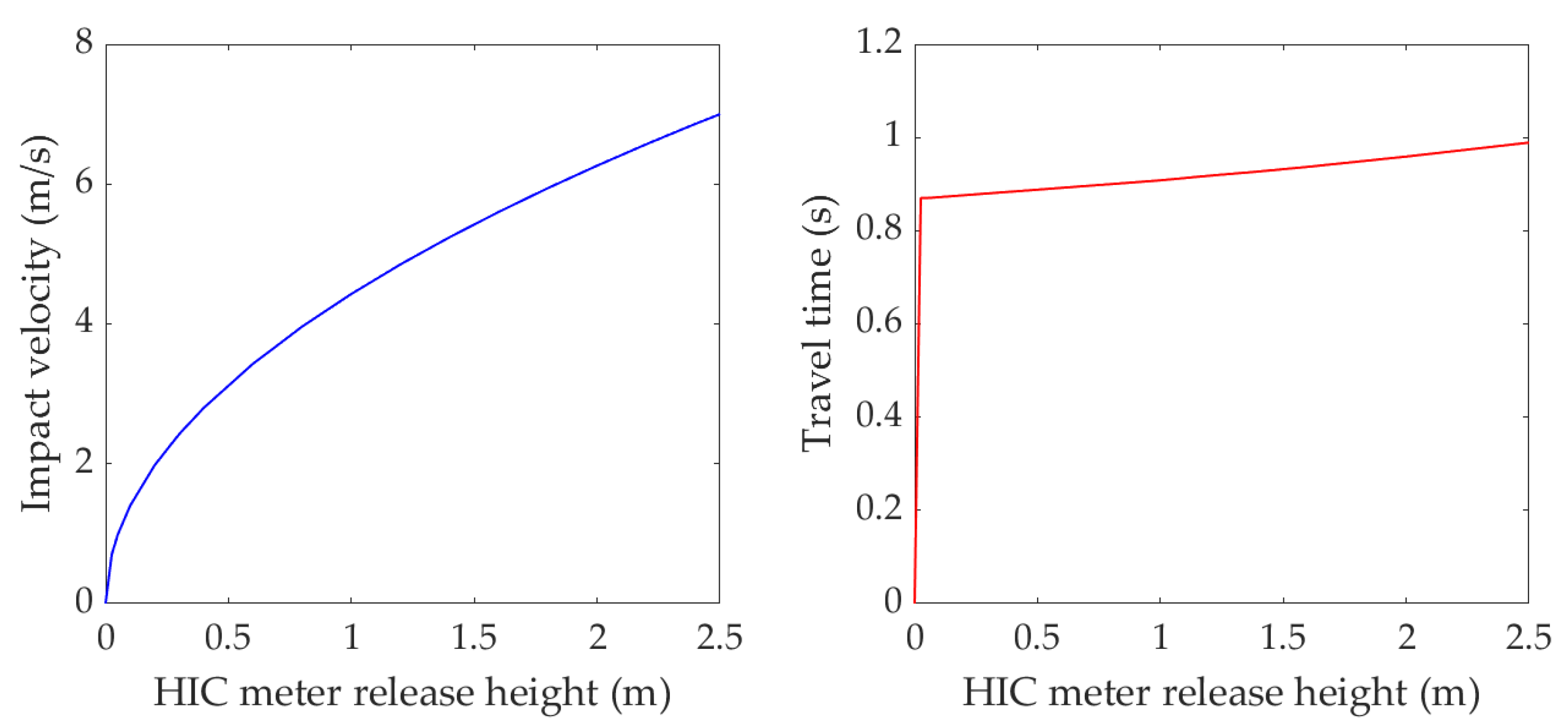
Based on Equation (3) and taking L as 3 m, the theoretical impact velocity of the HIC impact meter with different release heights h and travel times from height h to the impact position were calculated, as shown in Figure 14.
According to the law of conservation of energy, the HIC meter impact velocity can also be calculated by Equation (4), assuming all potential energy is transferred to kinetic energy.
v = 2 g h

4.1. On-Site Impact Test of the 75 mm-Thick Padding at the Greyhound Racing Track

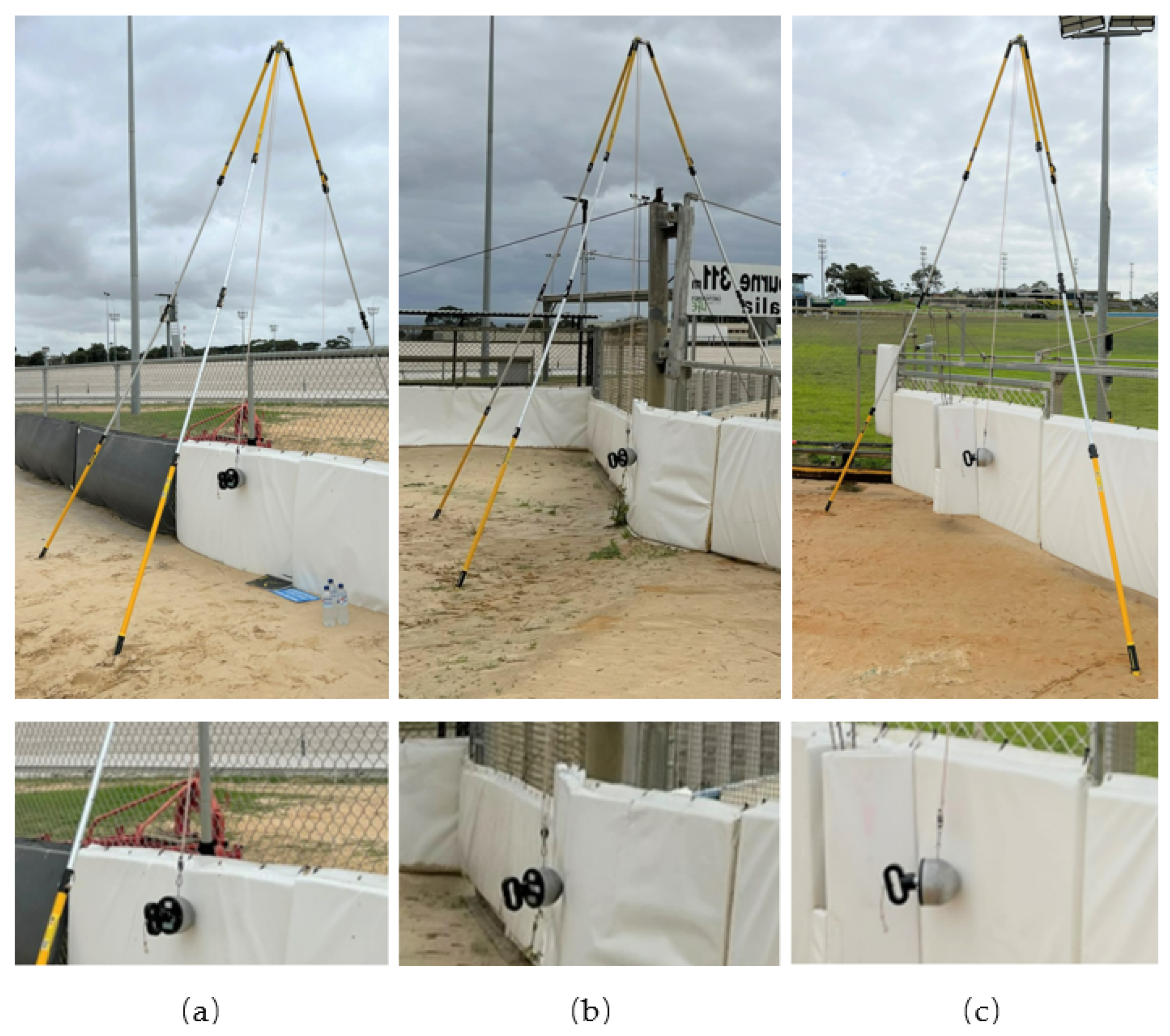
As shown in Figure 15, the 75 mm-thick padding is used at this greyhound racing track with different substrates, which provide different impact attenuation performance as a whole system. Therefore, on-site tests were conducted to assess the padding impact attenuation performance in-situ. At the various locations, the substrate was (a) corrugated steel panel; (b) stout steel mesh which was mostly rigid; and (c) thin steel mesh which had some flexibility. During the test, the HIC meter was lifted to different heights relative to its static position and released. For each height, three repeats were conducted and the average of these results determined. These are presented in Table 1. In the table, the impact velocity was calculated using Equation (4). For location (c), the minimum HIC impact meter release height was 1.15 m because the impact on the flexible mesh was insufficient to trigger the HIC impact meter data capture for release heights lower than this.
The average HIC and maximum acceleration at each location with different release heights are plotted in Figure 16 and Figure 17. The measured values were extrapolated through second-order polynomial fit. It was found that, even with identical padding, the impact attenuation performance was affected considerably by the underlying substrate. These values are much lower than those obtained from the laboratory test where the substrate was a concrete floor. The HIC and maximum acceleration at location (c) are smaller than at locations (a) and (b) due to the flexibility of the thin steel mesh. Thus, it is recommended that the padding should be tested after installation to ensure the impact attenuation performance meets the requirements. Furthermore, if the HIC 1000 and 200 g acceleration limits are used as the padding requirement criteria, all three locations suggest a safe greyhound impact for a 10 m/s velocity.

4.2. On-Site Impact Test of Other Padding Cases at the Greyhound Racing Track

On-site tests were also conducted at another greyhound racing track where different padding was used, as shown in Figure 18. Tests (a) and (b) were located at poles where the padding was tightly wrapped around the steel sections which had nearly no flexibility and was thereby more similar to the concrete substrate. During the test, the HIC impact meter was released, targeting directly on the poles. Test (c), on the other hand, was located at the catching pen gate. Here, the padding was installed on the steel mesh. For all three test locations, the HIC impact meter was lifted to 2.0 m and released. The static position height was 0.7 m, resulting in a fall height of 1.3 m and an impact velocity of 5.05 m/s.
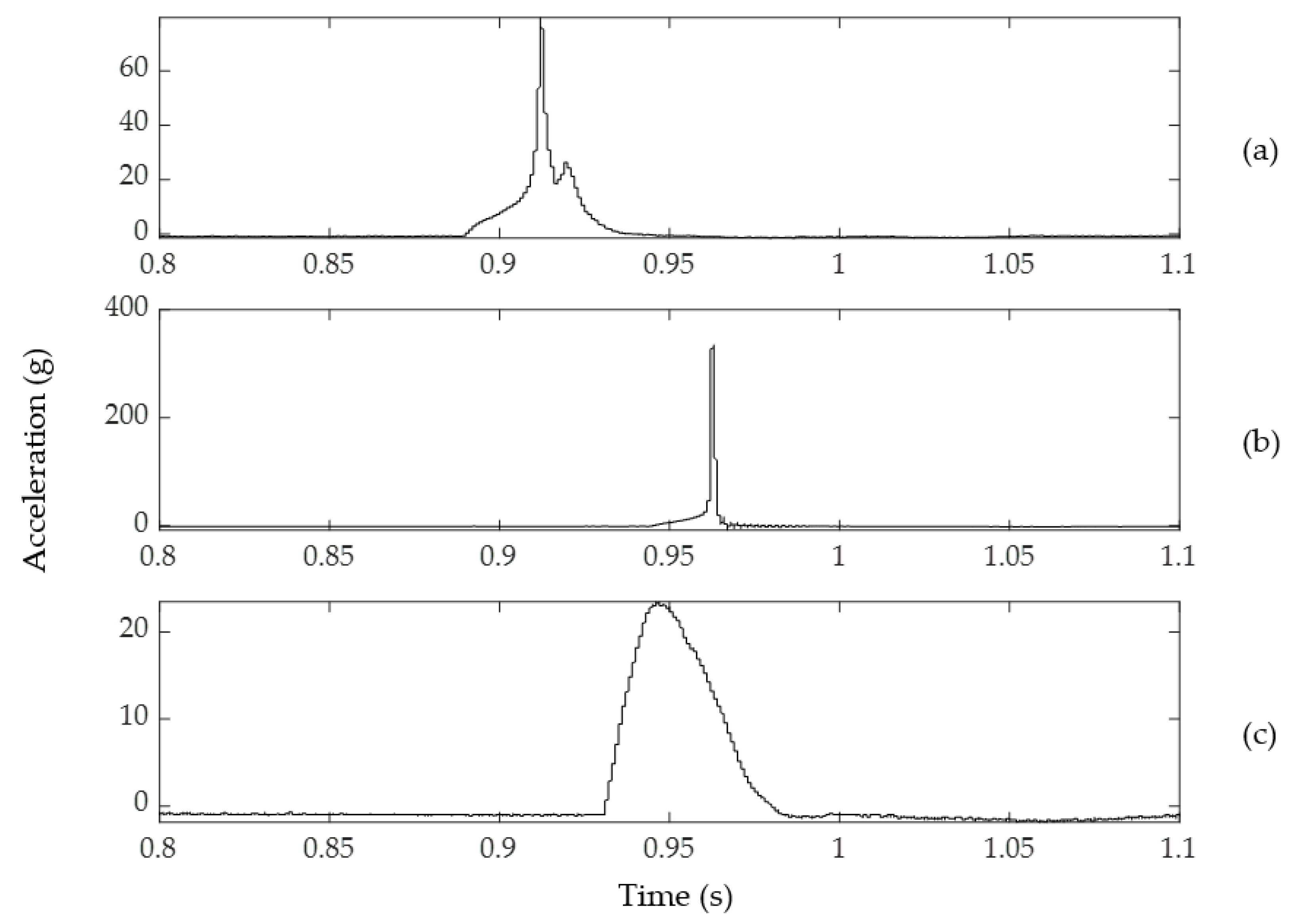
The measured HIC, HIC duration and maximum acceleration are presented in Table 2. A sample of the measured acceleration at each location is plotted in Figure 19. It can be observed that, when the padding was installed on the steel poles, the impact force was very large, as demonstrated by the large accelerations at location (b), indicating a potential safety hazard for greyhounds. Conversely, when the padding was installed on the steel mesh of the catching pen gate, the resulting impact force was relatively small, as shown in Figure 19c.
The steel mesh is more flexible than the steel poles. Therefore, longer impact duration and smaller accelerations are obtained with the steel mesh as the substrate. The test results at location (c) indicate that the steel poles remain hazardous to the greyhounds even with padding. It is concluded that extra padding or wrapping is required for these rigid poles.

5. Conclusions and Recommendations

This paper presents the results of an investigation into using impact-attenuating padding to reduce the likelihood of serious injuries associated with greyhounds impacting the outside fence and hard objects within the catching pens located at typical greyhound racing tracks.
The laboratory test results show that different padding systems have very different characteristics on impact attenuation and energy absorption. The laboratory tests obtained were different to what was expected. The laboratory tests were performed on a concrete substrate. On-site and in-situ testing was proposed to determine if testing on a concrete substrate could account for these unexpected results.
The on-site and in-situ test results for the greyhound racing track investigated in this study indicate that the padding currently used on the outside fence provides adequate protection from impact, owing in part to the fence flexibility and inherent impact attenuation properties. However, for harder/stiffer objects such as the steel poles, the impact forces observed with padding in place are significantly larger; this could lead to injury to greyhounds in the event of an impact. Thus, it is recommended that additional impact attenuation is required for these poles. Furthermore, considering there are no relevant standards for greyhound racing track padding, and various padding methods are adopted around the greyhound racing tracks, it is strongly recommended that, for padding to be properly deployed, it should be tested in-situ on the track to verify it provides satisfactory impact attenuation performance and sufficient protection for greyhounds.

Author Contributions

Conceptualization, D.E., S.Z. and I.H.; methodology, D.E., S.Z., I.H. and K.I.; software, S.Z. and I.H.; validation, D.E., S.Z., I.H., K.I. and B.H.; formal analysis, D.E., S.Z. and I.H.; investigation, D.E., S.Z. and I.H.; resources, D.E.; data curation, D.E., S.Z. and I.H.; writing—original draft preparation, D.E., S.Z. and I.H.; writing—review and editing, D.E., S.Z., I.H., K.I. and B.H.; visualization, S.Z. and I.H.; supervision, D.E. and B.H.; project administration, D.E.; funding acquisition, D.E. All authors have read and agreed to the published version of the manuscript.

Funding

This research was internally funded by the University of Technology Sydney.

Institutional Review Board Statement

Not applicable.

Informed Consent Statement

Not applicable.

Data Availability Statement

Not applicable.

Acknowledgments

The authors would like to thank Greyhound Racing Victoria for access to the various greyhound racing tracks where in situ impact testing was performed. They would particularly like to thank Scott Robins and Glenn Fish for the assistance they provided throughout this research project.

Conflicts of Interest

The authors declare no conflict of interest.

Abbreviations

The following abbreviations are used in this manuscript:
Δ tHIC duration
FPFinish post
g m a x Maximum acceleration
HICHead injury criterion
TPTransition point

References

  1. Leeworthy, D. A diversion from the new leisure: Greyhound racing, working-class culture, and the politics of unemployment in inter-war South Wales. Sport Hist. 2012, 32, 53–73. [Google Scholar] [CrossRef]
  2. Baker, N. Going to the dogs—Hostility to greyhound racing in Britain: Puritanism, socialism and pragmaticism. J. Sport Hist. 1996, 23, 97–119. [Google Scholar]
  3. Thayer, G.A. Going to the Dogs: Greyhound Racing, Animal Activism, and American Popular Culture; University Press of Kansas: Lawrence, KS, USA, 2013. [Google Scholar]
  4. Sicard, G.; Short, K.; Manley, P. A survey of injuries at five greyhound racing tracks. J. Small Anim. Pract. 1999, 40, 428–432. [Google Scholar] [CrossRef] [PubMed]
  5. Guilliard, M. Third tarsal bone fractures in the greyhound. J. Small Anim. Pract. 2010, 51, 635–641. [Google Scholar] [CrossRef] [PubMed]
  6. Iddon, J.; Lockyer, R.; Frean, S. The effect of season and track condition on injury rate in racing greyhounds. J. Small Anim. Pract. 2014, 55, 399–404. [Google Scholar] [CrossRef] [PubMed]
  7. Hossain, M.I.; Eager, D.; Walker, P.D. Greyhound racing ideal trajectory path generation for straight to bend based on jerk rate minimization. Sci. Rep. 2020, 10, 7088. [Google Scholar] [CrossRef] [PubMed]
  8. Eager, D.; Pendrill, A.M.; Reistad, N. Beyond velocity and acceleration: Jerk, snap and higher derivatives. Eur. J. Phys. 2016, 37, 065008. [Google Scholar] [CrossRef]
  9. Eager, D. Accelerometers used in the measurement of jerk, snap, and crackle. In Proceedings of the Australian Acoustical Society Annual Conference, AAS 2018, Adelaide, Australia, 7–9 November 2018. [Google Scholar]
  10. Hossain, M.I.; Eager, D.; Walker, P. Simulation of racing greyhound kinematics. In Proceedings of the SIMULTECH 2019—9th International Conference on Simulation and Modeling Methodologies, Technologies and Applications, Prague, Czech Republic, 29–31 July 2019. [Google Scholar]
  11. Hayati, H.; Eager, D.; Pendrill, A.M.; Alberg, H. Jerk within the Context of Science and Engineering—A Systematic Review. Vibration 2020, 3, 371–409. [Google Scholar] [CrossRef]
  12. Goodwin, A. Bundaberg’s First Greyhound Death of 2022. Available online: https://bundabergtoday.com.au/news/2022/03/23/bundabergs-first-greyhound-death-of-2022/ (accessed on 30 July 2022).
  13. Hayati, H.; Eager, D.; Stephenson, R.; Brown, T.; Arnott, E. The impact of track related parameters on catastrophic injury rate of racing greyhounds. In Proceedings of the 9th Australasian Congress on Applied Mechanics (ACAM9), Sydney, Australia, 27–29 November 2017; pp. 27–29. [Google Scholar]
  14. Starling, M.; Spurrett, A.; McGreevy, P. A pilot study of methods for evaluating the effects of arousal and emotional valence on performance of racing greyhounds. Animals 2020, 10, 1037. [Google Scholar] [CrossRef]
  15. Eager, D.; Hossain, I.; Ishac, K.; Robins, S. Analysis of Racing Greyhound Path Following Dynamics Using a Tracking System. Animals 2021, 11, 2687. [Google Scholar] [CrossRef] [PubMed]
  16. Eager, D. Undersurfacing—Myths and Facts; Kidsafe NSW Inc., Playground Advisory Unit: Sydney, NSW, Australia, 2003. [Google Scholar]
  17. Eager, D.; Chapman, C. Playground Surface Standards—A Discussion Paper. In Proceedings of the Kidsafe National Playground Conference, Sydney, NSW, Australia, 22–23 March 2004. [Google Scholar]
  18. Eager, D.; Chapman, C. Playground Impact Attenuating Sands; Australasian Parks and Leisure: Sydney, NSW, Australia, 2008. [Google Scholar]
  19. Eager, D. Playground Equipment and Surfacing Certification; Australasian Parks and Leisure: Sydney, NSW, Australia, 2009. [Google Scholar]
  20. Eager, D. Do Surfacing Standards Reflect Reality? International Conference Playground Fall Impacts; TüV Austria Academy: Brunn am Gebirge, Austria, 2013. [Google Scholar]
  21. Eager, D.; Hayati, H.; Chapman, C. Impulse force as an additional safety criterion for improving the injury prevention performance of impact attenuation surfaces in children’s playgrounds. In Proceedings of the ASME 2016 International Mechanical Engineering Congress and Exposition, Phoenix, AZ, USA, 11–17 November 2016. [Google Scholar]
  22. Eager, D.; Hayati, H. Additional injury prevention criteria for impact attenuation surfacing within children’s playgrounds. ASCE-ASME J. Risk Uncertain. Eng. Syst. Part B Mech. Eng. 2019, 5, 011002. [Google Scholar] [CrossRef]
  23. Chalmers, D.J.; Marshall, S.W.; Langley, J.D.; Evans, M.J.; Brunton, C.R.; Kelly, A.M.; Pickering, A.F. Height and surfacing as risk factors for injury in falls from playground equipment: A case-control study. Inj. Prev. 1996, 2, 98–104. [Google Scholar] [CrossRef] [PubMed] [Green Version]
  24. IsoLynx. The IsoLynx Real-Time Location System (RTLS) Athlete Tracking System. Available online: http://www.finishlynx.com/isolynx/ (accessed on 30 July 2022).
  25. Hayati, H.; Eager, D.; Walker, P. The effects of surface compliance on greyhound galloping dynamics. Proc. Inst. Mech. Eng. Part K J. Multi-Body Dyn. 2019, 233, 1033–1043. [Google Scholar] [CrossRef]
  26. McHenry, B.G. Head injury criterion and the ATB. ATB Users’ Group 2004, 29, 5–8. [Google Scholar]
  27. Yoon, J.M.; Lee, Y.; Park, S.O.; Han, Y.H.; Park, G.J. Crash optimization considering the head injury criterion. Proc. Inst. Mech. Eng. Part D J. Automob. Eng. 2019, 233, 2879–2890. [Google Scholar] [CrossRef]
  28. Mariotti, G.V.; Golfo, S.; Nigrelli, V.; Carollo, F. Head injury criterion: Mini review. Am. J. Biomed. Sci. Res. 2019, 5, 406–407. [Google Scholar] [CrossRef]
  29. Mackay, M. The increasing importance of the biomechanics of impact trauma. Sadhana 2007, 32, 397–408. [Google Scholar] [CrossRef] [Green Version]
  30. Eager, D.; Chapman, C.; Qi, Y.; Ishac, K.; Hossain, M.I. Additional Criteria for Playground Impact Attenuating Sand. Appl. Sci. 2021, 11, 8805. [Google Scholar] [CrossRef]
  31. AS 4422:2016; Playground Surfacing—Specifications, Requirements and Test Method. Standards Australia: Sydney, NSW, Australia, 2016.
  32. Z614:20; Children’s Playground Equipment and Surfacing. CSA: Toronto, ON, Canada, 2020.
  33. EN 1177-2018; Impact Attenuating Playground Surfacing—Methods of Test for the Determination of Impact Attenuation. CEN: Brussels, Belgium, 2018.
  34. F1292-18; Standard Specification for Impact Attenuation of Surface Materials within the Use Zone of Playground Equipment. ASTM International: West Conshohocken, PA, USA, 2018.
  35. Prasad, P.; Mertz, H.J. The position of the United States delegation to the ISO Working Group 6 on the use of HIC in the automotive environment. SAE Trans. 1985, 94, 106–116. [Google Scholar]
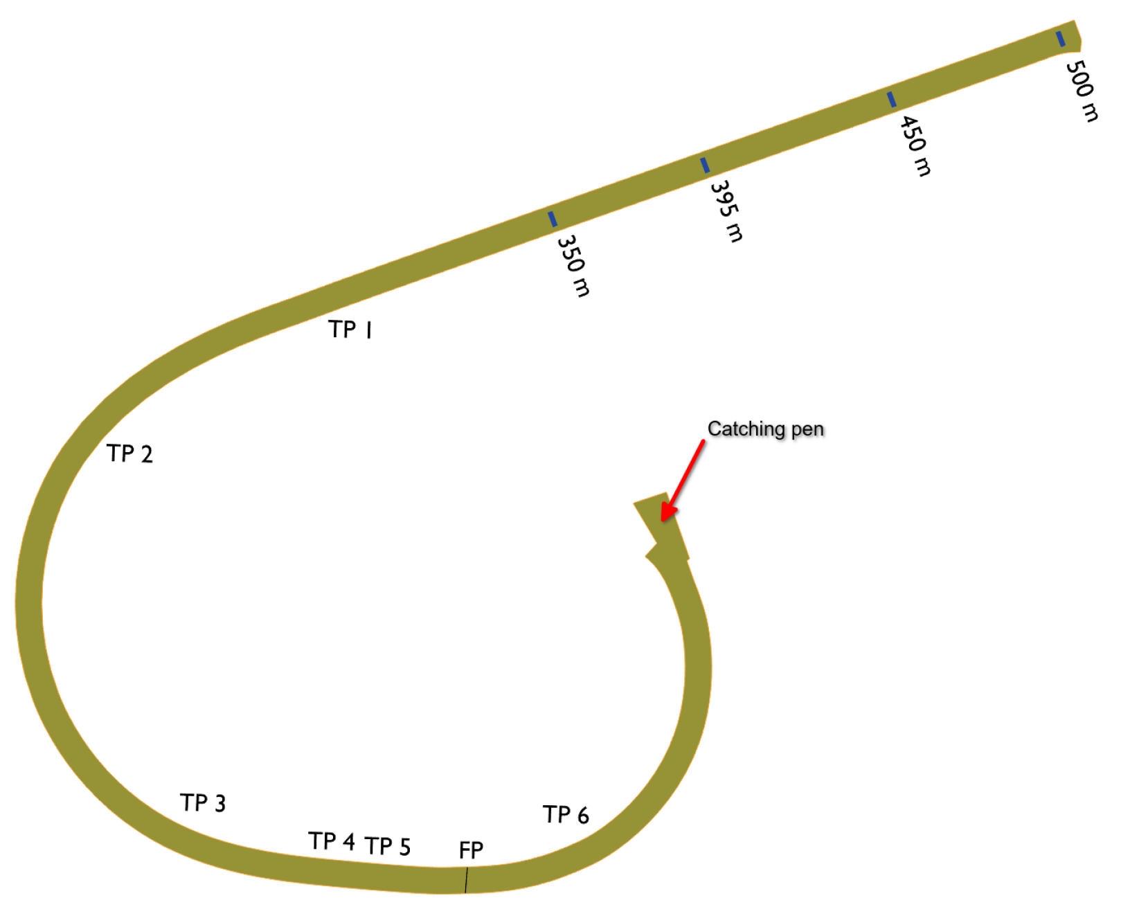
Figure 1. J-shaped greyhound racing track where greyhound racing speeds were obtained.
Vibration 05 00028 g001
Figure 2. Maximum and average instantaneous speed of racing greyhounds for the 350 m race distance (19 greyhounds).
Vibration 05 00028 g002
Figure 3. Maximum and average instantaneous speed of racing greyhounds for the 395 m race distance (16 greyhounds).
Vibration 05 00028 g003
Figure 4. Maximum and average instantaneous speed of racing greyhounds for the 450 m race distance (15 greyhounds).
Vibration 05 00028 g004
Figure 5. Maximum and average instantaneous speed of racing greyhounds for the 500 m race distance (24 greyhounds).
Vibration 05 00028 g005
Figure 6. Example of a greyhound colliding with the padding at an angle, before and after (ghost greyhound) impact.
Vibration 05 00028 g006
Figure 7. Different padding used at greyhound racing tracks on the outside fence.
Vibration 05 00028 g007
Figure 8. The HIC impact test meter used in this research.
Vibration 05 00028 g008
Figure 10. Laboratory impact test setup (LH) and three different padding thicknesses (RH).
Vibration 05 00028 g010
Figure 11. Measured HIC verses impact velocity in the laboratory test.
Vibration 05 00028 g011
Figure 12. Measured maximum acceleration verses impact velocity in the laboratory test.
Vibration 05 00028 g012
Figure 13. On-site impact test setup and its model for motion analysis, (a) on-site impact test setup; (b) model of the HIC meter motion.
Vibration 05 00028 g013
Figure 14. Theoretical HIC impact meter impact velocity and travel time.
Vibration 05 00028 g014
Figure 15. On-site impact test of the 75 mm thick padding with different substrates, (a) corrugated steel panel substrate; (b) stout steel mesh substrate; (c) thin steel mesh substrate.
Vibration 05 00028 g015
Figure 16. HIC with different substrates at a typical greyhound racing track.
Vibration 05 00028 g016
Figure 17. Maximum acceleration with different substrates at a typical greyhound racing track.
Vibration 05 00028 g017
Figure 18. Impact test of other padding cases, (a) catching pen thin pole; (b) catching pen large pole; (c) catching pen gate.
Vibration 05 00028 g018
Figure 19. Impact test measured accelerations, (a) catching pen thin pole; (b) catching pen large pole; (c) catching pen gate.
Vibration 05 00028 g019
Table 1. Impact test results of the 75 mm-thick padding at the greyhound racing track.
Location (a)Location (b)Location (c)
HeightVelocityTestHIC Δ tg max HIC Δ tg max HIC Δ tg max
(m)(m/s) (ms)(g) (ms)(g) (ms)(g)
0.753.8413028.50203325.8922
23028.41213226.0721
33028.14213226.1621
Average3028.3520.6732.3326.0421.33
0.954.3214326.97244325.3224
24326.73254424.5424
34326.88244324.8124
Average4326.8624.3343.3324.8924
1.154.7515924.84285524.27282737.2919
25924.45295524.33282836.2719
35824.54285624.30282835.5819
Average58.6724.6128.3355.3324.302827.6736.3819
1.355.1517323.37326423.70313634.9822
27723.25326923.34313534.0522
37223.73316723.16313533.6622
Average7423.4531.6766.6723.43135.3334.2322
1.555.5119622.14368122.65344431.6225
29321.99368522.05344432.5225
39222.23358521.69354730.1826
Average93.6722.1235.6783.6722.1334.334531.4425.33
1.755.86111722.98389921.90385129.7328
212220.944010321.45385528.5029
311521.183910321.24385229.2828
Average11821.739101.6721.533852.6729.1728.33
Table 2. Impact attenuation test results of other padding cases.
Location (a)Location (b)Location (c)
TestHIC Δ tg max HIC Δ tg max HIC Δ tg max
(ms)(g) (ms)(g) (ms)(g)
18712.728015151.353365029.3725
28313.057715091.353355129.6125
38612.758315391.263474929.5824
Average85.3312.848015211.32339.335029.5224.67
Publisher’s Note: MDPI stays neutral with regard to jurisdictional claims in published maps and institutional affiliations.