Article

Topological Acoustic Sensing Using Nonseparable Superpositions of Acoustic Waves

1
Department of Materials Science and Engineering, University of Arizona, Tucson, AZ 85721, USA
2
General Dynamics Mission Systems, 8220 East Roosevelt Street, Scottsdale, AZ 85257, USA
*
Author to whom correspondence should be addressed.
Vibration 2022, 5(3), 513-529; https://doi.org/10.3390/vibration5030029
Submission received: 30 June 2022 / Revised: 19 August 2022 / Accepted: 23 August 2022 / Published: 25 August 2022

Abstract

:
We introduce a method, topological acoustic sensing, which exploits changes in the geometric phase of nonseparable coherent superpositions of acoustic waves to sense mass defects in arrays of coupled acoustic waveguides. Theoretical models and experimental results shed light on the origin of the behavior and sensitivity of the geometric phase due to the presence of mass defects. The choice of the coherent superposition of waves used to probe the defects as well as the mathematical representation determining the topological characteristics of its space of states are shown to be critical in maximizing the sensitivity of the topological acoustic sensing method.

1. Introduction

The emerging field of topological acoustics (TA) is pushing the frontiers of sound science by revealing behaviors analogous to quantum mechanics [1,2,3]. The different degrees of freedom of TA waves offer intriguing opportunities to achieve quantum-like phenomena such as nonseparability, also known as “classical entanglement” [4,5]. Classical entanglement is associated with the occurrence of a multipartite tensor product structure in the state space representation of the wave. The space of states (i.e., Hilbert space) is an abstract parameter space and not the actual space in which sound propagates. This space is a composite space of subspaces associated with the individual degrees of freedom of the wave. In that composite space, the state of the acoustic wave is a product state. Classical entanglement is associated with the notion of inseparability between different degrees of freedom, whereby the composite Hilbert space can contain coherent superpositions of product states that are not algebraically separable into a single product. Consequently, the state of acoustic wave in the abstract Hilbert space can be characterized by its geometric phase. The total phase of a wave is the sum of the dynamical and geometric phases. The former relates to the time it takes an acoustic wave to travel at its velocity along some path in the space it propagates. However, the geometric phase depends on the degrees of freedom of this wave that form its Hilbert space. The state of this wave is a vector in the Hilbert space and depends on the direction of the state vector. The geometric phase accumulated along a path in state space represents the change in direction (or “angle”) of the state vector in the Hilbert space.
In general, using acoustic waves for sensing relies on changes in the wave attributes resulting from changes in the wave supporting medium. Changes in velocity, frequency, dynamical phase, or magnitude of the amplitude are commonly used in acoustic sensing technologies. Many research avenues also rely on exploiting non-linear effects of guided waves due to their sensitivity to small defects that would otherwise evade non-destructive evaluation [6]. Guided waves in laminated plates have also been investigated, showing that the sensitivity of guided waves is dependent on the frequency being used to probe a material [7]. Nondestructive evaluation will be necessary in ensuring the integrity of composite materials [8] and continuous monitoring of structures and infrastructure [9,10]. The utility of guided waves is present in the existing literature on nondestructive evaluation, however, the geometric phase of coherent states of waves has yet to be explored.
Only very recently has the possibility of using the geometric phase for acoustic sensing been investigated theoretically. The geometric phase of acoustic waves scattered by diatomic molecules adsorbed on a solid surface was shown to be strongly dependent on the arrangement of the molecules. The geometric phase was particularly sensitive to the configuration of the adsorbates near their resonant frequency [11]. This approach was extended to waves of much larger wavelength, namely seismic waves. We introduced an acoustic sensing approach that exploited the geometric phase of ground-supported seismic waves resulting from their scattering by trees in forested environments [12]. Using a simulated model forest with different spatial arrangements of trees as a testbed, we calculated numerically the geometric phase of acoustic waves and showed that it is very sensitive to the spatial pattern of trees. Furthermore, we showed that exploitation of seismic waves as a remote sensing platform for environmental monitoring is a novel avenue for detecting changes in subsurface temperatures that effect the properties of the permafrost in the arctic [13]. In that work, we used the geometric phase of seismic waves due to scattering by trees in a forest as a means of detecting global changes in permafrost stiffness. We note again that this approach is particularly sensitive to changes at frequencies near the resonance of the tree since large changes in geometric phase are expected near resonances.
In the present paper, we report the first experimental demonstration of topological acoustic sensing using the geometric phase of nonseparable acoustic waves. Recent work has demonstrated experimentally the possibility of creating “classically entangled” elastic waves in externally driven parallel arrays of coupled one-dimensional metallic acoustic waveguides [4,5]. These nonseparable coherent superpositions of acoustic states, analogous to Bell states, are constructed out of products of a spatial eigen mode part and a plane wave part. The plane waves characterize the acoustic wave along the length of the waveguides and the spatial eigen modes describe the amplitude and phase variation across the array of waveguides. These states lie in the tensor product Hilbert space of the two-dimensional subspaces associated with the degrees of freedom along and across the waveguide array. Here, we investigate the effect of mass defects (i.e., mass scatterers attached locally to the array of waveguides) on the nonseparable superpositions of product states. We show that mass scatterers effectively rotate the state vector of the nonseparable waves in its state space. The geometrical phase associated with this rotation is demonstrated experimentally to be a very sensitive metric for detecting the presence of the scatterers. We also establish that there is no theoretical limit to the sensitivity of this method.
This paper is organized as follows. In Section 2, we present theoretical models of coupled acoustic waveguides in the absence and presence of mass defects. This model system enables us to shed light on the origin of the effect of mass scatterers on the geometric phase of coherent superpositions of acoustic product states. In Section 3, we report on the experimental system, set up and methods for investigating the effect of mass scatterers on nonseparable superpositions of acoustic waves in externally driven arrays of coupled acoustic waveguides. By bringing the non-separable superpositions of states through the external drivers within a region of the state space where the geometric phase is very sensitive to perturbations, we observe significant effects on the phase due to the presence of mass scatterers. In Section 4, we discuss the experimentally observed behavior and sensitivity of the sensing method using a phenomenological argument. Finally, this work shows that the choice of the initial superposition of states is critical in maximizing the sensitivity of topological acoustic sensing methods. Conclusions are drawn in Section 5.

2. Theoretical Models

2.1. Coupled Waveguide System in Absence of Defects

We consider a system composed of three coupled elastic waveguides taking the form of one-dimensional mass-spring chains (Figure 1).
The chain and coupling springs obey linear elasticity. The discrete linear elastic equations of motion are given by:
m 2 u n t 2 β ( u n + 1 2 u n + u n 1 ) α ( v n u n ) + η u n t = 0 ,
m 2 v n t 2 β ( v n + 1 2 v n + v n 1 ) α ( u n v n ) α ( w n v n ) + η v n t = 0 ,  
m 2 w n t 2 β ( w n + 1 2 w n + w n 1 ) α ( v n w n ) + η w n t = 0
In Equations (1)–(3), u n ,   v n and w n are the displacements of n t h mass of top, middle, and lower chains, respectively. m is the mass, and the viscous damping coefficient η models the dissipation. Here we take the coupling constant between chains, α , to be the same for all coupled chains. We seek solutions in the form of plane waves, ( u n v n w n ) = A e i k n a e i ω t , with the amplitude vector A = ( a u a v a w ) . Inserting this ansatz into Equations (1)–(3), we obtain the eigen value problem:
( γ I + α C ) A = 0
where γ = m ω 2 + i η ω + 4 β ( sin k a 2 ) 2 , I is the 3 × 3 identity matrix and the coupling matrix C   takes the form ( 1 1 0 1 2 1 0 1 1 ) . The eigen vectors of the coupling matrix are spatial eigen mode isomorphic to orbital angular momenta (OAM) [14]. The three normalized OAM eigen vectors corresponding to the eigen values λ 1 = 0 , λ 1 = 1 , and λ 3 = 3 , are: e 1 = ( e 1 u e 1 v e 1 w ) = 1 3 ( 1 1 1 ) ,   e 2 = ( e 2 u e 2 v e 2 w ) = 1 2 ( 1 0 1 ) ,   e 3 = ( e 3 u e 3 v e 3 w ) = 1 6 ( 1 2 1 ) . Replacing A in Equation (4) by these eigen vectors, gives the associated dispersion relations for plane wave solutions,
m ω 0 , 1 2 i η ω 0 , 1 = 4 β ( sin k a 2 ) 2
m ω 0 , 2 2 i η ω 0 , 2 = 4 β ( sin k a 2 ) 2 + α
m ω 0 , 3 2 i η ω 0 , 3 = 4 β ( sin k a 2 ) 2 + 3 α
The coupled elastic system is then driven externally with the external force   F 0 = ( F 1 F 2 F 3 ) e i ω t = F e i ω t applied at n = 0 .
The equations of motion of the driven coupled system become:
m 2 u n t 2 β ( u n + 1 2 u n + u n 1 ) α ( v n u n ) + η u n t = F 1 e i ω t δ n , 0
m 2 v n t 2 β ( v n + 1 2 v n + v n 1 ) α ( u n v n ) α ( w n v n ) + η v n t = F 2 e i ω t δ n , 0
m 2 w n t 2 β ( w n + 1 2 w n + w n 1 ) α ( v n w n ) + η w n t = F 3 e i ω t δ n , 0
The δ n , 0 is the Kronecker delta and ensures the location of the driver. We expand the driving force over the OAM basis:
F = f 1   e 1 + f 2   e 2 + f 3   e 3
where f j = e j F for j = 1 , 2 , 3 .
We seek solutions of Equations (8)–(10) in the form of plane waves that try to follow the driving frequency: ( u n v n w n ) = A e i k n a e i ω t with the amplitude vector expanded in the OAM basis, A = A 1   e 1 + A 2   e 2 + A 3   e 3 . By inserting this ansatz and Equation (11) into Equations (9) and (10) and by using the undriven dispersion relations given by Equations (5)–(7), we obtain:
A j ( k j ) = f j m ( ω 01 2 ( k i ) ω 2 ) i η ( ω ω 0 , i )
For j = 1 , 2 , 3 . These amplitudes are complex quantities because of the dissipation term.
Equations (8)–(10) relate to infinite chains, however, in the case of more realistic finite length spring-mass chains, one deals with a finite set of modes labeled by a discrete set of wavenumbers. The general form of the displacement field will take the form:
( u n v n w n ) = ( k A 1 ( k )   e 1 e i k n a + k A 2 ( k )   e 2 e i k n a + k A 3   ( k ) e 3 e i k n a ) e i ω t
where the sums are over the discrete wavevectors, k , k , k , associated with the modes of the finite length system.
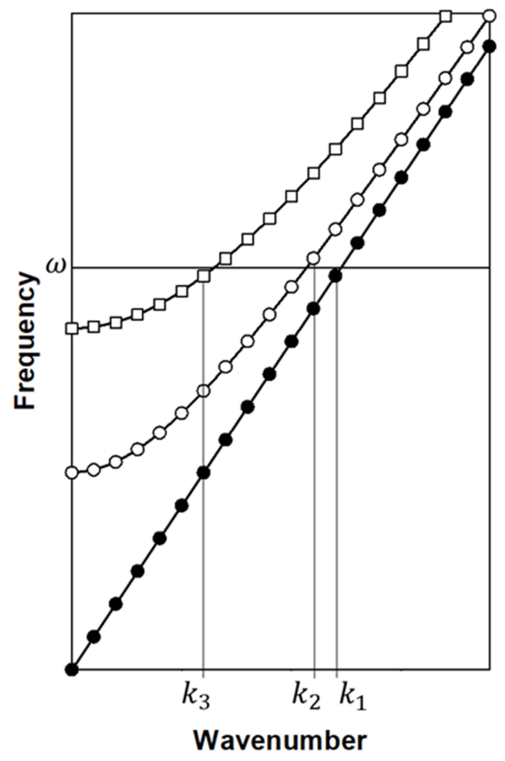
In light of the Lorentzian line shape of the amplitudes A 1 , 2 , 3 , it is possible to conceive the use of isofrequency drivers which minimize the amplitude of some modes and maximize others (Figure 2). This approach will reduce the number of wavenumbers that will contribute significantly to a driven displacement field which defines the values of k , k , k , uniquely. We note that by manipulating the driving frequencies and driving amplitudes we can choose any of the possible combination of k values and OAMs. It is therefore possible to create a driven displacement field that includes only one wave number for each OAM:
( u n v n w n ) = ( A 1 ( k 1 )   e 1 e i k 1 x + A 2 ( k 2 )   e 2 e i k 2 x + A 3   ( k 3 ) e 3 e i k 3 x ) e i ω t
In Equation (14) we us the position variable x = n a . Furthermore, by exploiting the orthogonality of the OAM basis vectors, one would also be able to employ a driving force F which is only a linear combination of e 2 and e 3 . In that case f 1 = 0 and A 1 ( k ) will have only negligible magnitude, thus reducing the number of terms in Equation (14) from three to two. This approach can also be used to reduce Equation (14) to pure states with one single OAM.
We now envision the Hilbert space of elastic waves that are products of the three OAM eigen vectors and three corresponding plane wave terms. The basis for this 32 dimensional space are e 1 e i k 1 x , e 1 e i k 2 x , e 1 e i k 3 x , e 2 e i k 1 x , e 2 e i k 2 x , e 2 e i k 3 x , e 3 e i k 1 x , e 3 e i k 2 x , e 3 e i k 3 x . The superposition of waves represented by Equation (14) is a unique vector in this complex Hilbert space, , with complex components, A j ( k j ) , that are phase locked as these amplitudes are generated by the same driving force. The angle this vector makes with some reference vector in this space is the geometric phase of the superposition. This state is also representative of a nonseparable state and cannot be written as a product of a linear combination of OAM vectors and a linear combination of the three plane waves. Such states have been demonstrated experimentally [4].
One of the key properties of acoustic waves of the form given by Equation (14) for topological acoustic sensing is coherence. By coherence, we mean that the complex amplitudes, A 1 , A 2 and A 3 are not independent of each other. A perturbation such as a scatterer will modify all three amplitudes simultaneously. This property is analyzed in next subsection.

2.2. Coupled Waveguide System with Mass Defects

The defected three-waveguide system is illustrated in Figure 3.
The equations of motion of this defected system are the same as Equations 1–3 everywhere along the waveguides but at the location of the defects. The location of the defect is taken as n = 0 . Considering harmonic waves with angular frequency, ω , the equations of motion at the defect location read:
m ω 2 u 0 = β ( u 1 2 u 0 + u 1 ) + α ( v 0 u 0 )
m ω 2 v 0 = β ( v 1 v 0 + v 1 ) + α ( u 0 v 0 ) + α ( w 0 v 0 )
m ω 2 w 0 = β ( w 1 w 0 + w 1 ) + α ( v 0 w 0 )
In Equations (15)–(17), we have omitted the dissipative term for the sake of clarity and simplicity. We will do the same for the equations of motion in the nondefected region of the system. To account for dissipation, one may replace terms of the form m ω 2 and m ω 2 by m ω 2 i η ω and m ω 2 i η ω .
We now address the scattering of plane waves with the three different OAM eigen vectors.

2.3. Scattering of an e 1 Mode

We consider an incident wave that is scattered by the defects into a reflected wave and a transmitted wave. The incident and reflected waves live on the same side of the system with respect to the defects e.g., left side. The transmitted wave is located on the opposite side of the defect as well as at the defect location.
At n = 0 , the ansatz we choose for the incident and scattered waves are:
( u 1 v 1 w 1 ) = a i e 1 e i k 1 a e i ω t + a r e 1 e i k 1 a e i ω t
( u 0 v 0 w 0 ) = a t ( γ 1 δ 1 1 ) e i ω t
( u 1 v 1 w 1 ) = a t e 1 e i k 1 a e i ω t
Note that at the defect site the vector ( γ 1 δ 1 1 ) differs from e 1 because of the difference in the masses m and m . Note also that the reflected wave in Equation (18) propagates in a direction opposite to that of the incident wave. The quantities a i , a r and a t are the amplitudes of the incident, reflected and transmitted waves. We have the conservation of amplitude constraint a i + a r = a t . For simplicity, assuming no local resonances, we normalize these amplitudes to that of the incident wave such that the constraint reduces to
1 + R 1 = T 1
where R 1 = a r / a i and T 1 = a t / a i . R 1 and T 1 are therefore the sought reflection and transmission coefficients. Similarly, we express the ansatz of Equations (18)–(20) in terms of R 1 and T 1 by normalizing them with respect to a i . Inserting the normalized Equations (18)–(20) into Equations (15)–(17) and using Equation (21), we obtain four equations for the four unknowns: γ 1 , δ 1 , R 1 and T 1 .
After extensive algebraic manipulations, we obtain the solution:
R 1 = N 1 N 1 i 4 β sin k 1 a
With
N 1 = ( m δ 1 m ) ω 2 + 2 β ( δ 1 1 ) + α ( δ 1 γ 1 )
and
γ 1 = ( 2 β + α ) m ω 2 ( 2 β + α ) m ω 2
δ 1 = ( 2 β + 3 α ) m ω 2 + α ( γ 1 1 ) ( 2 β + 3 α ) m ω 2
In the limit of m = m , γ 1 = 1 , δ 1 = 1 , N 1 = 0 and R 1 = 0 , that is there is no scattering.
In obtaining Equations (22)–(25), we have made use of the dispersion relation given by Equation (5). The reflection coefficient, R 1 , is complex. If we account for dissipation, the coefficients γ 1 and δ 1 are also complex quantities and affect the phase of the reflection coefficient. Therefore R 1 carries a phase that is a complicated function of the wave number, angular frequency, and physical parameters of the systems including the mass of the defect.

2.4. Scattering of an e 2 Mode

At n = 0 , the normalized ansatz we choose for the incident and scattered waves are:
( u 1 v 1 w 1 ) = 1 e 2 e i k 2 a e i ω t + R 2 e 2 e i k 2 a e i ω t
( u 0 v 0 w 0 ) = T 2 ( γ 2 δ 2 1 ) e i ω t
( u 1 v 1 w 1 ) = T 2 e 2 e i k 2 a e i ω t
We also have 1 + R 2 = T 2 . Following a procedure similar to that of Section 2.3, we obtain:
R 2 = N 2 N 2 i 4 β sin k 2 a
With
N 2 = ( m γ 2 m ) ω 2 + ( 2 β + α ) ( γ 2 1 )
and
γ 2 = ( m ω 2 + 2 β + α ) ( m ω 2 + 2 β + 2 α ) 2 α 2 ( m ω 2 + 2 β + α ) ( m ω 2 + 2 β + 2 α ) 2 α 2
δ 2 = α ( γ 2 1 ) m ω 2 + 2 β + 2 α
In obtaining Equations (29)–(32), we have made use of the dispersion relation given by Equation (6).
One easily verifies that the limit m = m leads to no scattering.

2.5. Scattering of an e 3 Mode

At n = 0 , the normalized ansatz we choose for the incident and scattered waves are:
( u 1 v 1 w 1 ) = 1 e 3 e i k 3 a e i ω t + R 3 e 3 e i k 3 a e i ω t
( u 0 v 0 w 0 ) = T 3 ( γ 3 δ 3 1 ) e i ω t
( u 1 v 1 w 1 ) = T 3 e 3 e i k 3 a e i ω t
and 1 + R 3 = T 3 . For this mode we find the reflection coefficient:
R 3 = N 3 N 3 i 4 β sin k 3 a
With
N 3 = ( m γ 3 m ) ω 2 + ( 2 β + α ) ( γ 3 1 ) 2 α ( δ 3 + 2 )
And
γ 3 = ( m ω 2 + 2 β + α ) ( m ω 2 + 2 β + α )
δ 3 = 2 ( m ω 2 + 2 β ) + α ( γ 3 1 ) m ω 2 + 2 β
We again verify that the reflection coefficient vanishes when the mass of the scatterers is the same as that of the masses in the waveguides.

2.6. Scattering of a Nonseparable Superposition of States

If we considered an incident wave that is generated by driving the system such that the displacement field is given by Equation (14), the transmitted wave will be a superposition of states of the form:
( u n v n w n ) T = ( ( 1 + R 1 ) A 1 ( k 1 )   e 1 e i k 1 x + ( 1 + R 2 ) A 2 ( k 2 )   e 2 e i k 2 x + ( 1 + R 3 ) A 3 ( k 3 ) e 3 e i k 3 x ) e i ω t
The frequency, ω , in Equation (40) is that of the external driver.
Since the coefficients ( 1 + R 1 ) ,   ( 1 + R 2 ) and ( 1 + R 3 ) are complex quantities and carry amplitude and phase, they act on the incident wave (Equation (14)), by rotating its corresponding state vector in the complex space H. The rotation depends on the scattering masses through the coefficients, γ and δ . Writing A j ( k j ) = | A j ( k j ) | e i ϕ j ( k j ) for j = 1 , 2 , 3 , we find ϕ j ( k j ) = tan 1 ( η ω m ω 0 j 2 ( k j ) m ω 2 ) . Writing the transmission coefficients, T j = 1 + R j = | T j | e i φ j , the displacement field (Equation (40)) at some location, x = l a can be rewritten as:
( u n v n w n ) T = ( ( 1 + R 1 ) A 1 ( k 1 )   e 1 e i k 1 x + ( 1 + R 2 ) A 2 ( k 2 )   e 2 e i k 2 x + ( 1 + R 3 ) A 3 ( k 3 ) e 3 e i k 3 x ) e i ω t
or effectively:
( u l v l w l ) T = ( | u l | e i θ u | v l | e i θ v | w l | e i θ w )
Equations (40) and (42) are two different representations of the same transmitted displacement. The first representation is in the complex Hilbert space, , or equivalently in the Hilbert subspace, S , which basis vectors are ζ 1 = e 1 e i k 1 x , ζ 2 = e 2 e i k 2 x and ζ 3 = e 3 e i k 3 x . The second representation is in the space, R , with the basis ρ 1 = ( 1 0 0 ) , ρ 2 =   ( 0 1 0 ) and ρ 3 = ( 0 0 1 ) corresponding to the first, second and third rods, respectively. We can reduce this second representation by normalizing all components in Equation (42) to that of the first rod, namely
( u ^ l v ^ l w ^ l ) T = ( 1 | v l | | u l | e i θ u v | w l | e i θ u w )
It is therefore possible to measure the rotation induced by the scatterers by measuring the relative phase of the displacement field between the first and the second waveguides and the first and third waveguides at l, namely θ u v = θ v θ u and θ u w = θ w θ u . In this representation, the displacement of the first waveguide serves as reference.
We note that the superposition of state given by Equation (41) can only be made separable if two of these amplitudes A j , j = 1 , 2 , 3 , are identically zero, that is, if the external driving force is chosen such that two of the f j , are zero in Equation (11). The only separable states are therefore the pure e 1 , e 2 , or e 3 modes. For the three pure modes, the transmitted waves are simply multiplied by the transmission coefficients T 1 , T 2 , and T 3 , respectively. Each of these complex transmission coefficients will add a general phase to the pure modes which cannot be detected in an experiment by measuring the relative phase between rods. In contrast, a nonseparable coherent superposition of states such as that of Equation (40) will lead to a measurable change in relative phase between rods as a result of scattering. In this latter case, one exploits the coherence of the superposition of states.
In the next section, we implement an experiment to quantify the sensitivity of the geometric phase of nonseparable superpositions of waves to mass scatterers, i.e., explore the effect of mass scatterers on Equation (43).

3. Experiments

3.1. Experimental System and Set Up

The experimental array of parallel acoustic waveguides consists of three aluminum rods (6061 aluminum with diameter 1.27 cm, length L = 0.609 m, and density 2660 kg / m 3 ). In the long wavelength limit, aluminum rods with large length-to-diameter ratios approximate well the 1D waveguides. We have filled a lateral gap of 2 mm between adjacent rods with epoxy (50176 KwikWeld Syringe, Sulphur Springs, TX, USA) uniformly. We have verified experimentally that epoxy provides the dissipation needed to achieve complex resonant amplitudes [4]. Ultrasonic spectroscopy is used to characterize the behavior of the system. For this we use two sets of longitudinal wave transducers (V133-RM, Olympus IMS, Tokyo, Japan) to drive and detect the waves at the rod ends, x = 0   and x = L , respectively. The three driving transducers connect to waveform generators (B&K Precision 4055B, Yorba Linda, CA, USA) through PD200 amplifiers (high bandwidth, low-noise linear amplifier). The detecting transducers connect to a Tektronix oscilloscope (MDO3024) to record signals and provide temporal and spatial DOF information across the array. A rubber band (Walmart, Bentonville, AR, USA, 564755837) is stretched to encompass each of the three rods and their associated driving and detecting transducers. The tension of the rubber bands helps ensure that the pressure on each of the transducers is uniform. This uniform pressure also helps to eliminate air bubbles and create an even layer of ultrasonic couplant. Each transducer was coupled to the aluminum rods using honey. The high viscosity of the honey results in better coupling between the transducers and rods because it provides a better acoustic impedance match (2.89 MPa m−2) with the aluminum (11.88 MPa m−2). The waveguide array/transducers assembly is suspended by two thin threads to isolate the system from the environment.
A mass scatterer is constructed by using two magnets. The attractive magnetic force binds the two magnets across the epoxy region coupling the top and middle rods as seen in Figure 4. Magnetic force enables physical contact between the rods and the magnets, thus adding mass locally to the top two waveguides in the array. This experimental system approximates the defected system of Figure 3. The magnets are located at a distance x = 305 cm from the driven ends. The magnets are rectangular prisms with length 1.905 ± 0.001 cm and square base of side length 0.497 cm. The mass of each magnet is 3.47 ± 0.01 g. The mass of the undefected array of rods is 666.21 ± 0.01 g, therefore the defects constitute 1 % of the mass of the undefected system.

3.2. Experimental Results

3.2.1. Properties of the Externally Driven Undefected Array of Waveguides

An experiment is carried out by first stimulating the coupled waveguides with driving forces that select each of the OAM eigen vectors at one end of the rods and recording the transmission at the other end of the rods (Figure 5a). The transmission spectra recorded at rod 1 are shown in Figure 5b. For recording, we chose rod 1 in contrast to rod 2 as none of the amplitudes of the eigen vectors are zero there.
The finite length rods show well defined resonant peaks in the transmission spectrum that are dependent on the stimulated mode and correspond to discrete values of wavenumbers associated with standing waves. The resonant peaks have Lorentzian line shapes indicative of dissipation. The e 1 mode exhibits resonant peaks at low frequency since its corresponding band is without cutoff. The other two modes do not show significant transmission at low frequency because of the cutoff frequencies associated with their respective bands. Because the three driving transducers are not perfectly identical, a combination of driving voltages applied to the stimulating transducers with the intent of generating a pure mode may not lead to a force that excites only one single OAM. The resonant peaks with structure in Figure 5(b and inset) most likely reflect primarily the excitation of the desired mode with some additional component of the other modes, that is, a superposition of states. In Figure 5(b inset), we focus on the transmission spectrum in the vicinity of 25 kHz. Here, the e 2 and e 3 modes have well defined overlapping resonant peaks near 25.1 kHz. At that frequency, the e 1 transmission should exhibit a trough between two of its resonances. However, the slight shoulder observed may result from the partial excitation of that OAM. We choose the frequency of 25.1 kHz for all subsequent experiments.

3.2.2. Transmitted Amplitude and Phase of Nonseparable Superposition of States in Un-defected System

Here we stimulate the undefected system with a driving force F = ( F 1 = r F 2 F 2 F 3 = 0 ) . The parameter r enables us to tune the probing superposition of states (Figure 6a). All values of the parameter r will generate nonseparable coherent superpositions of states which is a requirement for observing a measurable change in relative phase between rods. We will vary r between 0 and 2 while keeping F 2 constant. For instance, when r = 1 , F ( 1 1 0 ) and according to Equation (11), since f 1 = 0 and f 2 = f 3 , the superposition is that of the two e 2 and e 3 modes.
For a general value of r, f 1 = r 1 , f 2 = r , and f 3 = r + 2 . Only f 1 changes sign as r changes through 1. The contribution of the e 1 mode to the superposition for r < 1 will be out of phase with that when r > 1 . We therefore anticipate that θ u v will not change as a function of r, while in contrast the phase differences θ u w and θ v w ought to undergo a π phase change at r = 1 . This phase change is clearly seen in Figure 6c. We also note that the magnitude of the amplitude of the first and second rods are nearly constant and that the magnitude of the amplitude of the third rod varies linearly with r with an expected a minimum at   r = 1 . What we see here is a parametric rotation of the representation of the superposition of states given by Equation (41) within the space S or equivalently a rotation of the representation of Equation (43) in the space of the rods, R . This rotation, however, is controlled extrinsically through the driving force. The parameter r will then be used to select superpositions of states of the undefected system with optimal sensitivity to probe the presence of defects. In Section 3.2.3, we will quantify the effect of scattering masses onto the probe superpositions of states spanned by the driving parameter r .

3.2.3. Transmitted Amplitude and Phase of Nonseparable Superposition of States in Defected System

We perform the same experiment as that of Section 3.2.2 with the system containing the mass defects. The overall behavior of the magnitude of the amplitude and of the phase differences between rods is qualitatively similar to that of the undefected system. However, in Figure 7, we plot the difference Δ θ = θ v w ( defected ) θ v w ( undefected ) as a function of r.
This measurement shows that by making an appropriate choice of non-separable superposition of state and of representation of this superposition, the change in geometric phase between the un-defected and defected systems can vary significantly. Indeed, at r~1 Δ θ ~ 44 ° . We recall that the change in geometric phase Δ θ is a rotation in the space, R , due to the presence of the defects. In contrast the change in magnitude of the amplitude is only ~13%. It is clear from Figure 7 that not all nonseparable superpositions of acoustic waves are sensitive to mass defects. For r < 1 , Δ θ approaches monotonously zero. However, for r > 1 , Δ θ plateaus rapidly to a nearly constant value of ~6°. The choice of the initial superposition within a given representation is therefore critical in maximizing the sensitivity of topological acoustic sensing methods. This point is discussed below.

4. Discussion

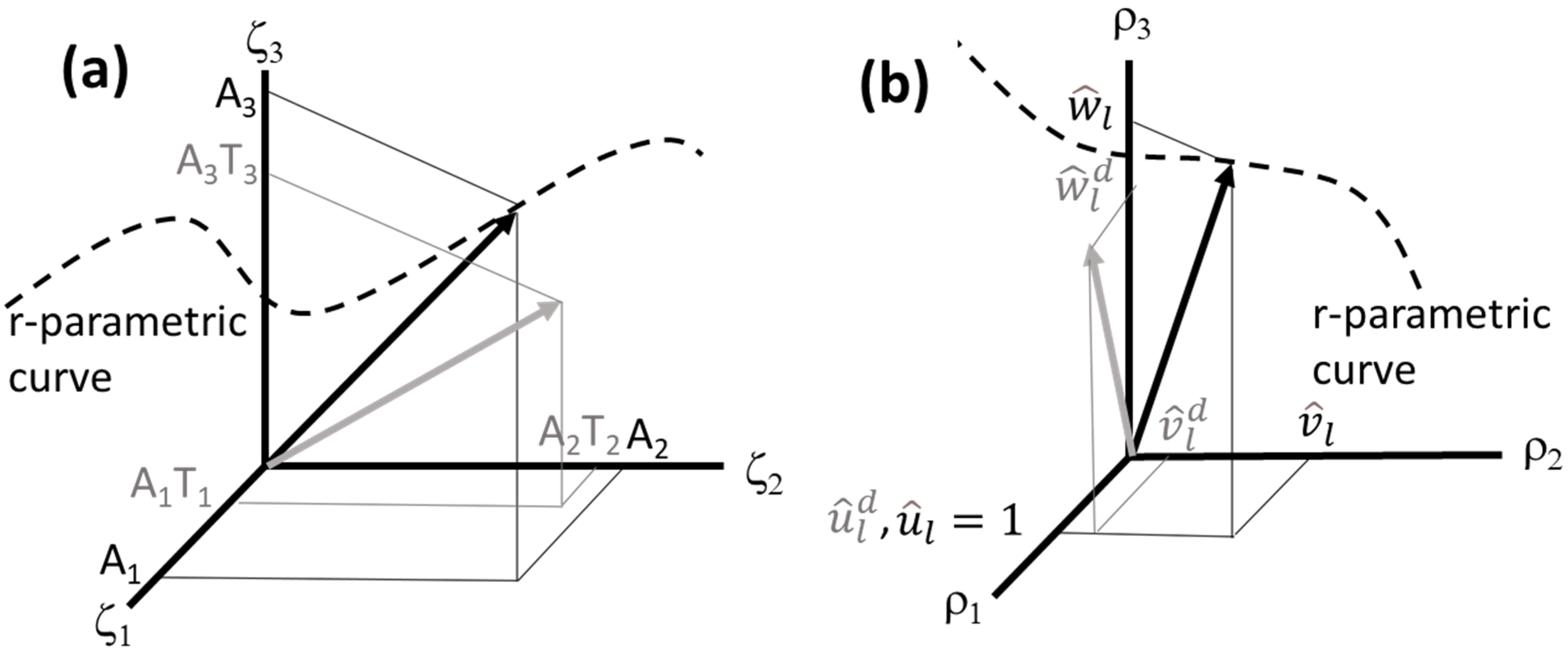
The navigation of the state spaces, S and R by varying the driving parameter r is illustrated schematically in Figure 8. Of course, these spaces are complex and are represented here as simple cartesian spaces for the sake of simplicity. A topological interpretation of the experimental results will be proposed by considering how driving conditions affect the observed phase differences by projecting the state vector on the driving parameter coordinate, r.
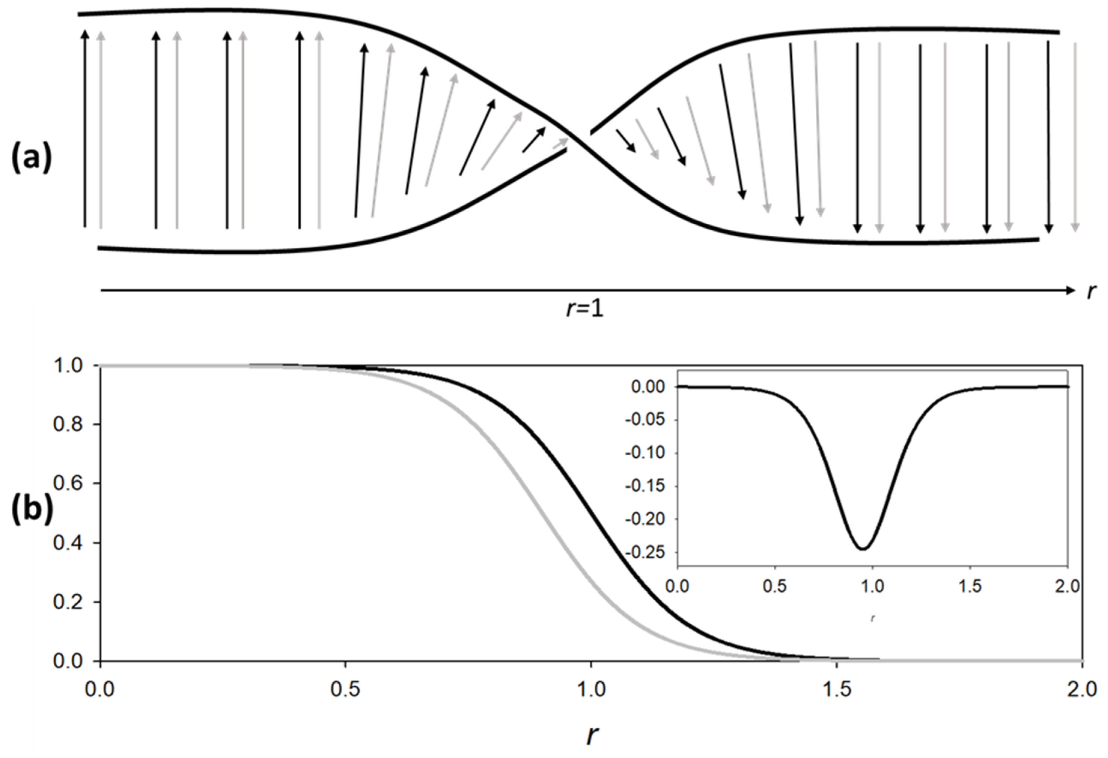
Figure 8 illustrates schematically the rotation of state vectors due to a change in driving force. It also shows, for a given driving force, the rotation due to mass defects. To shed light on the origin of the results of Figure 7, we simplify this illustration further. We reframe the rotation due to variations in the driving parameter r as the parallel transport of a vector on a manifold [15] constituted of a ribbon with a twist, a non-trivial topological feature. Here, we focus on the variations of the third component of the representation in the space of rods as measured by θ v w . Position along the ribbon is r itself. In this phenomenological illustration, rotation in the state spaces is reduced to translations along the ribbon manifold. The twist is located at r = 1 where θ v w undergoes a π phase change (Figure 6c). This ribbon is illustrated in Figure 9a. As the state vector of the undefected system is transported (i.e., translated) parallel to the ribbon, it is undergoing a rotation of π . Since the state vector of the defected system is rotated with respect to the state vector of the un-defected system by scattering, this rotation is equivalent to a translation on the ribbon. This translation may therefore lead to a π phase change that occurs prior to r = 1 . The difference in phase between the undefected and defected systems, when plotted again r , is therefore showing a minimum in the vicinity of r = 1 . The inset of Figure 9 is qualitatively in very good agreement with the experimental results of Figure 7. For r > 1 , the difference between the experimental measurements (constant Δ θ > 0 ) and the phenomenological interpretation ( Δ θ = 0 ) may result from the idealization of the ribbon manifold. In the experimental system, the manifold may retain some constant twist character for r above 1.
The rapid variation of θ v w ( r ) near r = 1 provides the sensitivity for the detection of the mass defects through measurements of the change in geometric phase. In the phenomenological model and the experiment, this variation is sigmoidal with a finite width. However, considering the ideal case of a stepwise change in θ v w ( r ) (i.e., a ribbon with an infinitesimally narrow twist), one may achieve a maximum drop in Δ θ of up to π . The width of that depression will depend on the amount of rotation in state space (or the corresponding amount of translation on the ribbon manifold) due to scattering. Strong scattering will lead to wider depressions in Δ θ ( r ) while weak scattering will lead to narrower depressions. In the limit of infinitesimally small masses, the depression may reduce to a delta peak. Therefore, the sensitivity of topological acoustic sensing depends on the shape of θ u w ( r ) . There is no theoretical limit to the magnitude of the mass of defects that can be detected. From an experimental point of view, the sensitivity will depend on the ability to control continuously the driving forces, i.e., r and on the accuracy of the measurement of phase.

5. Conclusions

We experimentally demonstrate a topological acoustic sensing method which uses the geometric phase of nonseparable coherent superpositions of acoustic waves in externally driven parallel arrays of coupled acoustic waveguides. The nonseparable coherent superpositions of acoustic states, are products of OAM states and plane wave states. These states can be described by a tensor product Hilbert space of the two-dimensional subspaces associated with the degrees of freedom along and across the waveguide array. A theoretical model is developed to shed light on the ways one can rotate the superposition of states within the system’s Hilbert space, i.e., change the geometric phase. We also consider a change of representation of the complex displacement field from the product Hilbert space to the space of the rods themselves. Within that latter space, rotations of superpositions of states are more easily measured. We show that rotation can be achieved through the external drivers by adjusting the driving force applied to each rod. A scattering theory of mass defects attached locally to the array of waveguides shows that mass scatterers also effectively rotate the state vector of the wave. By probing, through the external drivers, nonseparable superpositions within a region of the space of states where the geometric phase is very sensitive to perturbations, we observe a significant effect on the geometric phase due to the presence of mass scatterers. This work shows that by making a pertinent choice for the probe superposition as well as its representation, one can maximize the sensitivity of topological acoustic sensing methods.
Insights from this work may be relevant to other technologically important systems such as large cables in suspension bridges composed of smaller coupled cables which are structurally similar to the coupled rod array. The sensing method introduced and described here is not limited to detecting defects in such arrays. The concept of geometric phase is universal and independent of the physical characteristics of the acoustic wave supporting medium. The supporting medium or structure determines the topological characteristics of the acoustic wave state space. Topological acoustic sensing may therefore be applicable to monitor a large variety of media and structures which exhibit acoustic wave state spaces with useful topological attributes.

Author Contributions

All authors contributed equally to the research and writing of the paper. All authors have read and agreed to the published version of the manuscript.

Funding

This research was funded partially by General Dynamics Mission Systems.

Institutional Review Board Statement

Not applicable.

Informed Consent Statement

Not applicable.

Data Availability Statement

Data available upon reasonable request to corresponding author.

Acknowledgments

T.D.L., P.A.D. and K.R. are grateful for financial support from General Dynamics Mission Systems.

Conflicts of Interest

The authors declare no conflict of interest.

References

  1. Deymier, P.A.; Runge, K. Sound Topology, Duality, Coherence and Wave-Mixing: An Introduction to the Emerging New Science of Sound; Springer Series in Solid-State Sciences; Springer International Publishing AG: Cham, Switzerland, 2017; Volume 188. [Google Scholar]
  2. Huber, S.D. Topological Mechanics. Nat. Phys. 2016, 2, 621. [Google Scholar] [CrossRef]
  3. Pal, R.K.; Ruzzene, M. Edge waves in plates with resonators: An elastic analogue of the quantum valley Hall effect. New J. Phys. 2017, 19, 025001. [Google Scholar] [CrossRef]
  4. Hasan, M.A.; Calderin, L.; Lata, T.; Lucas, P.; Runge, K.; Deymier, P.A. The Sound of Bell States. Nat. Commun. Phys. 2019, 2, 106. [Google Scholar] [CrossRef]
  5. Hasan, M.A.; Calderin, L.; Lata, T.; Lucas, P.; Runge, K.; Deymier, P.A. Deymier, Experimental Demonstration of Elastic Analogues of Nonseparable Qutrits. Appl. Phys. Lett. 2020, 116, 164104. [Google Scholar] [CrossRef]
  6. Lissenden, C.J. Nonlinear ultrasonic guided waves–Principles for nondestructive evaluation. J. Appl. Phys. 2021, 129, 021101. [Google Scholar] [CrossRef]
  7. Schall, C.; Maal, A. Core-skin disbond detection in a composite sandwich panel using guided ultrasonic waves. ASME J. Nondestruct. Eval. 2017, 1, 011006. [Google Scholar] [CrossRef]
  8. Liu, S.; Liu, F.; Yang, Y.; Li, L.; Li, Z. Nondestructive evaluation 4.0: Ultrasonic intelligent nondestructive testing and evaluation for composites. Res. Nondestruct. Eval. 2020, 31, 370–388. [Google Scholar] [CrossRef]
  9. Dib, G.; Padiya, J. High performance wireless sensors system for structural health monitoring. AIP Conf. Proc. 2012, 1430, 1583. [Google Scholar]
  10. Galvagni, A.; Cawley, P. Guided wave permanently installed pipeline monitoring system. AIP Conf. Proc. 2012, 1430, 1591. [Google Scholar]
  11. Deymier, P.A.; Runge, K. Phase properties of elastic waves in systems constituted of adsorbed diatomic molecules on the (001) surface of a simple cubic crystal. J. Appl. Phys. 2018, 123, 125106. [Google Scholar] [CrossRef]
  12. Lata, T.D.; Deymier, P.A.; Runge, K.; Le Tourneau, F.-M.; Ferrière, R.; Huettmann, F. Topological Acoustic Sensing of Tree Spatial Patterns in a Model Forest. Ecol. Model. 2020, 419, 108964. [Google Scholar] [CrossRef]
  13. Lata, T.D.; Deymier, P.A.; Runge, K.; Ferrière, R.; Huettmann, F. Topological acoustic sensing of ground stiffness: Presenting a potential means of sensing warming permafrost in a forest. Cold Reg. Sci. Tech. 2022, 199, 103569. [Google Scholar] [CrossRef]
  14. Deymier, P.A.; Runge, K.; Vasseur, J.O.; Hladky, A.-C.; Lucas, P. Elastic waves with correlated directional and orbital angular momentum degrees of freedom. J. Phys. B Mol. Opt. Phys. 2018, 51, 135301. [Google Scholar] [CrossRef] [Green Version]
  15. Hobson, M.O.; Efstathiou, G.; Lasenby, A.N. General Relativity: An Introduction for Physicists; Cambridge University Press: Cambridge, UK, 2006. [Google Scholar]
Figure 1. Schematic illustration of the system composed of three coupled one-dimensional elastic waveguides. The small springs couple the three elastic chains which masses are interacting via the large springs.
Vibration 05 00029 g001
Figure 2. Illustration of the dispersion relation for the three elastically coupled waveguides. The value ω is the driving frequency of the driving force. The wavenumber of the modes with the largest amplitudes at ω has been highlighted on the x-axis. Since the amplitudes for each state are Lorentzian, states farther away from the driving frequency will have smaller amplitude.
Vibration 05 00029 g002
Figure 3. Schematic illustration of the system composed of three coupled one-dimensional elastic waveguides with two mass defects (two larger spheres with mass m’).
Vibration 05 00029 g003
Figure 4. Image of defected array of three coupled aluminum rod waveguides. The image shows the rubber bands flanking the rods. The magnet scatterers are binding to the groove made by the top two rods. In the image only one side of the array of waveguides and one magnet are visible.
Vibration 05 00029 g004
Figure 5. (a) Schematic of the approach used to measure the transmission spectrum for each OAM eigen vector. The three different driving forces are illustrated at the right of the array of waveguides. (b) Transmission spectrum of the three OAM modes reported as peak-to-peak voltage of the detecting transducer versus driving frequency. The driving frequency is varied between 0 and 60 kHz by increments of 200 Hz. Inset magnification of the transmission spectrum around 25.1 kHz.
Vibration 05 00029 g005
Figure 6. (a) Schematic of the approach used to measure the amplitude at and the phase differences between the rods when stimulated with a driving force, F = ( r F 2 , F 2 , 0 ) . (b) Magnitude of the amplitude (expressed as peak-to-peak voltage) at the detector end of each rod (labelled 1, 2, and 3) as a function of the driving parameter r. (c) Phase differences θ u v ,  θ v w and θ u w between displacement fields at the detector ends of the rods. The frequency of the drivers is 25.1 kHz.
Vibration 05 00029 g006
Figure 7. (a) Phase difference between rods 2 and 3, θ v w , with and without defect. (b) Measured Δ θ = θ v w ( defected ) θ v w ( undefected ) as a function of driving parameter r .
Vibration 05 00029 g007
Figure 8. Navigating the state spaces, (a) S and (b) R by varying the driving parameter r . The state vector in absence of defects, represented by a solid arrow, is given by (a) a coherent superposition of product states with basis ζ 1 , ζ 2 , and ζ 3 i.e., Equation (14) and (b) the corresponding representation in the space of rods in the basis ρ 1 , ρ 2 and ρ 3 i.e., Equation (43) The locus of points spanned by the state vector of the undefected and defected systems as r is varied are shown as dashed lines. The state of the transmitted wave in both systems corresponding to the same r as that of black arrows are represented as grey arrows. The grey arrow spans another r -parametric curve (not drawn). The components of the state vectors for the defected system are labelled in grey with an upper script d for (b).
Vibration 05 00029 g008
Figure 9. (a) Schematic illustration of the twisted ribbon manifold supporting the state vector of the un-defected (black arrows) and defected (grey arrows) arrays of waveguides a r is varied. The grey arrows are translated to the right along the r axis leading to an additional rotation for a given r due to scattering. (b) Rotation angle of the state vectors, θ v w , (in units of π ) for the undefected (black line) and defected (grey line) systems. Inset, Δ θ = θ v w ( defected ) θ v w ( undefected ) as a function of driving parameter r.
Vibration 05 00029 g009
Publisher’s Note: MDPI stays neutral with regard to jurisdictional claims in published maps and institutional affiliations.