Article

Practical Modal Analysis of a Prototyped Hydrogenerator

1
Institute for Drive Systems and Power Electronics, Leibniz University Hannover, 30167 Hannover, Germany
2
Voith Hydro Holding GmbH & Company KG, 89522 Heidenheim, Germany
*
Author to whom correspondence should be addressed.
Vibration 2021, 4(4), 853-864; https://doi.org/10.3390/vibration4040048
Submission received: 15 September 2021 / Revised: 26 October 2021 / Accepted: 29 October 2021 / Published: 10 November 2021
(This article belongs to the Special Issue Computation and Design of Renewable Energy Systems)

Abstract

:
The vibration on the stator core of hydrogenerators caused by electromagnetic forces is an important factor affecting the reliability and long-lasting operation of a machine. For a suitable addressment of the problem, it is necessary to accurately predict the eigenmodes and eigenfrequencies of the mechanical system. However, different results for the eigenfrequencies can be achieved depending on the applied model and material parameters. This work contributes to solving this issue by investigating the impact of different input parameters on the eigenmodes and eigenfrequencies calculated by analytical and numerical models. The results are discussed and compared to measurements performed on a prototyped 732 kVA hydrogenerator.

1. Introduction

Hydropower generation represents an important source of renewable energy. In order to keep high indexes of availability to the grid, maximize the energy production, and achieve low costs for power generation, it is crucial to maintain power plants’ maintenance expenses to a minimum. This can be done by avoiding common problems on the equipment already in the early design phase, such as excessive vibrations in the generator. This paper contributes to advancing this field by performing investigations on a stator mechanical model, which is used for predicting stator cores’ radial vibrations in hydrogenerators due to alternating magnetic forces. Such forces are commonly interpreted as the superposition of rotating magnetic pressure waves originated from the airgap magnetic field, which acts predominantly on the core laminations in the radial direction [1]. In combination with the dynamic response of the mechanical system, they may cause excessive vibration of the stator core and other structures, which is generally undesirable due to possible damage, life span reduction, and consequent audible noise.
In the particular case of hydrogenerators, which are commonly low-speed salient-pole synchronous machines, the mechanical structure has some peculiarities. One of them is that the stator frame has a significant influence on the excited eigenmodes [2]. As illustrated in Figure 1, low-speed hydrogenerators are normally vertical machines, and their stator frames consist of shelves and structural columns that transmit the stator, rotor, and turbine weight to the housing foundations [3]. In these cases, it is common that the stator core yoke is relatively thin compared to the frame shelves radial height, which increases the influence of the stator frame. Taking into account these effects for such a large structure in a time and cost-effective manner is quite a real challenge, since available analytical models assume the stator core only as a free cylinder in space. On the other hand, FE models depend substantially on the accuracy of the employed equivalent material’s properties and boundary conditions at the interfaces between frame, core, and foundations.
Several analytical models are available for calculating the stator frequency response at different mode shapes. Most of them are based on a simplified thick cylinder model, as in Jordan [4], Arnold and Warburton [5], White [6], and Girgis and Verma [7]. Experimental measurements are available in Verma and Girgis [8,9] and Verma and Balan [10] for different types of stators, but for small-sized machines. Although some of these models allow to consider simply supported boundary conditions at the cylinder axial ends, they are not able to correctly take into account the effect of the stator frame of a hydrogenerator. There are also more complex FE models and measurements for large hydrogenerators including the stator frame, as in Minnier et al. [11], Rau [12], and Zhou et al. [13]. In these studies, different considerations were made regarding the influence of teeth, yoke, winding, frame, and foundations; however, there is still a debate on the most suitable material properties for stacked laminations, winding, and correct contact conditions at the interface between frame and core. In the last years, several works were dedicated to the establishing suitable material parameters for small-sized machines [14,15,16,17,18], but the specific case of hydrogenerators has not been addressed yet. For the equivalent Young’s modulus of a stator core in the axial direction, values from ~4 GPa [17] to ~110 GPa [18] can be found. The effect of ventilation ducts is mentioned by Walker [19] only for static tests. For the winding equivalent Young’s modulus, measurements are available for a single bar hanging on space [12], but the effect of a bar fixation system inside the slot has not been assessed.
The present work aimed to perform mechanical modal analyses of the stator structure varying the material properties and contact conditions between core and frame. The effect of each factor is discussed in relation to the performed measurements.

2. Materials and Methods

In order to evaluate the mechanical response of the core, we developed an FE model for a prototyped hydrogenerator. This evaluation was also carried out using an existing analytical model, so that the results could be compared to those obtained with the FE model. The machine main data are summarized in Table 1.
Firstly, several modal analyses for different material parameters and boundary conditions were performed. Then, an experimental modal analysis (EMA) was carried out, and the eigenmodes and frequencies predicted by the different calculation models were compared.

2.1. Analytical Model

The applied analytical model was developed according to White [6], which described the stator core as a thin-walled cylinder with thickness corresponding to the stator yoke. The stator teeth were considered only as additional mass to the system, in order to account for their kinetic energy during vibration. However, the stiffness of the teeth was not considered, following the assumption that they did not experience any deformation, but rather followed the displacement according to the surrounding yoke. This simplification was also assumed for the winding inside the slots.
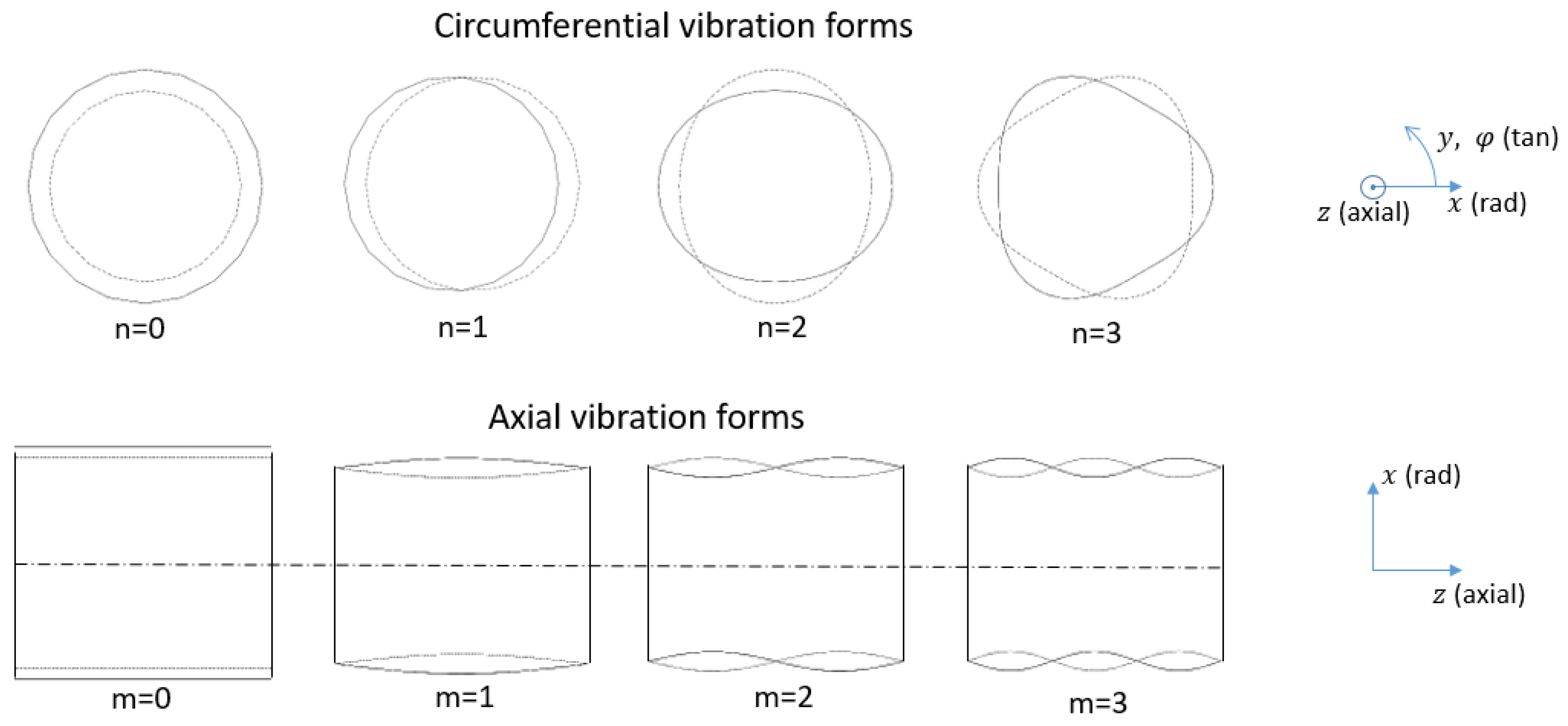
The analytical calculation of the eigenfrequencies followed the approach of applying Lagrange’s equations on the kinetic energy and strain energy of a vibrating cylindrical shell. Equations (1) and (2) illustrate the involved energies. The complete development up to the eigenfrequencies can be found in detail in [6]. This approach led to the expected eigenmodes, also known as mode shapes, as shown in Figure 2.
S = 1 2 λ 0 2 π 0 l 1 2 h 1 2 h [ E z e z ² + E y e y ² + 2 μ y x E z e z e y + λ G z y γ z y ² ]   a   d x d z d φ
T = ρ 2 0 2 π 0 l 1 2 h 1 2 h [ ( d u d t ) 2 + ( d v d t ) 2 + ( d w d t ) 2 ] a   d x d z d φ
where S is the total strain energy, T is the total kinetic energy, a is the mean radius, h is the core yoke thickness, l is the core length, e i is the direct strain in direction i, γ i j is the shear strain in direction i j , E i : is the Young’s modulus in direction i , G i j is the shear modulus in direction i j , ρ is the equivalent mass density, μ i j is the Poisson ratio in direction i j , λ = 1 μ y z μ x y .
The displacements of the cylinder intermediate surface in the directions x, y, and z are represented by the variables the u, v, and w, respectively. In Equation (1), the stator was assumed as a thin cylinder and, consequently, the direct strain in the radial direction e x and the shear strains involving the radial direction ( γ x z and γ x y ) were neglected. The trapezoidal shape of the elements in the yoke due to the cylindrical geometry was also not taken into account.
After application of Lagrange’s equations and some mathematical development (as described in [6]), the result is a system of differential equations in terms of the displacements of the cylinder intermediate surface. Such differential equations allow the determination of the system eigenfrequencies for each of the eigenmodes.
In general, mode shapes with displacement in all three directions are possible in this model. However, in this paper, only the mode shapes with dominant radial and axially uniform displacements will be discussed, since those are the ones excited by axially uniform radial magnetic forces.

2.2. Finite-Element Model

In this study, the core was modeled in three dimensions using the software ANSYS (2021 R1, ANSYS Inc, Canonsburg, PA, USA) as a solid body instead of a stack of laminations, and the material properties were defined as homogenized input parameters. The effects of air ducts and laminations were then simplified by adjusting the axial stiffness of the equivalent orthotropic material ( E z ) . With this approach, the Poisson’s ratio and shear modulus of the material were also adjusted according to the values of E z , using the homogenization formulas from [6]:
μ x z = μ x y E z E y
G x y = E x 2 ( 1 + μ x y )
G x z = E x E z E x ( 1 + μ x z ) + E z ( 1 + μ x y )
The winding inside the slots was also modeled as consisting of equivalent blocks, according to Figure 3a. The material properties were assumed to be isotropic, and the end winding region was neglected. The stator frame geometry was imported using a detailed Computer-Aided Design (CAD). It consisted of structural plates and columns, a set of double-dovetail bars, and pressure fingers. The double-dovetail bars were designed to provide tangential support and allow radial thermal expansion of the core, and the pressure fingers were responsible for keeping the core sheets axially compact. Due to its complexity, careful simplifications were made to ensure a reasonable computation time while also preserving the accuracy of the FE model. All thin bodies and plates on the outer part of the frame—which are represented in Figure 3b—were replaced by two-dimensional shell elements following the assumption that deformations along the suppressed dimensions were negligible. This avoided having 3D elements with a poor aspect ratio, which would lead to calculation inaccuracy or excessive computation time. The stator pressure fingers and the double-dovetail bars, which were in direct contact with the core, were kept as 3D elements.
The boundary conditions for the connection between the stator yoke and the double-dovetail bars of the frame, illustrated in Figure 3c, were set to either bonded, neglecting the yoke’s possible displacement designed for thermal radial expansion, or frictionless, neglecting any movement resistance in the contact region.
In an FE modal analysis, the system mass and stiffness matrices are determined to obtain the basic dynamic differential Equation (6), where mechanical damping is neglected, and the external forces are set to zero:
M d ² x ( t ) d t ² + K x ( t ) = 0
Following a diagonalization process, as in [20], the system can be decoupled based on the transformation matrix Ψ formed by the system eigenvectors ψ i (7). Each eigenvector can be arbitrarily scaled. Typically, the mass matrix is used for the scaling, giving the orthogonality relation in Equation (8). The output of the FE modal analysis are the system eigenvectors, which represent the natural mode shapes of the structure, and the eigenfrequencies associated to each one of them, as described in (9), where r = 1 n .
Ψ = [ ψ 1 ,   ψ 2     ψ n ]
Ψ T M   Ψ = I = d i a g ( 1 )
Ψ T K   Ψ = d i a g ( ω 0 ( r ) 2 )
In general, mode shapes with displacement in all three directions are possible. However, in this paper, only the mode shapes with dominant radial and axially quasi-uniform displacements will be discussed, since those are the ones excited by axially uniform radial magnetic forces.

2.3. Validation Measurements on a Prototyped Hydrogenerator

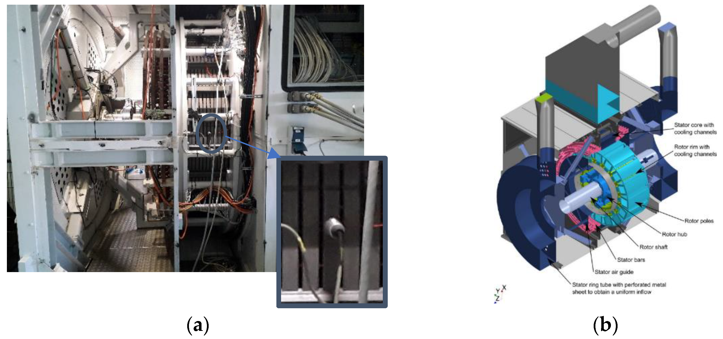
For validation of the model, an experimental modal analysis (EMA) was performed on a prototyped hydrogenerator. An instrumented hammer with sensitivity of 0.24 mV/N was used, and a 100 mV/g accelerometer was installed in the back of the stator core, at an intermediate axial height (Figure 4).
The experimental modal analysis was performed by exciting the tested structure at different points with the instrumented hammer, while the accelerometer recorded the system response at a fixed position. By dividing the FFT of the accelerometer signal by the FFT of the hammer signal, the frequency response function (FRF) for each excited point is obtained. Due to the reciprocity property of linear mechanical systems, the transfer function is equal when applying the excitation in point A and evaluating the response in point B or vice-versa (excitation in B and evaluation in A) [21]. Therefore, it is possible to obtain the structure’s natural mode shapes and eigenfrequencies based on the obtained FRFs. In the analyzed prototyped hydrogenerator, a total of 120 points were excited in the back of the stator yoke. Those were equally distributed in 5 axial rows, each one with 24 points around the circumference. The tested machine is illustrated in Figure 4b.

3. Results

The results from the calculation models and measurements are compared in the following sections. Different material properties were analyzed for the simulations, as summarized in Table 2, where x is the radial direction, y is the tangential direction, and z is the axial direction.
The mass density of the winding was defined by dividing the total mass of the winding, including insulation and overhang, by the volume of the equivalent body representing the winding inside the slots in the FE model. Furthermore, two different contact conditions between stator core and double-dovetail bars were evaluated: bonded and frictionless.

3.1. Comparison between Models Using Different Input Parameters

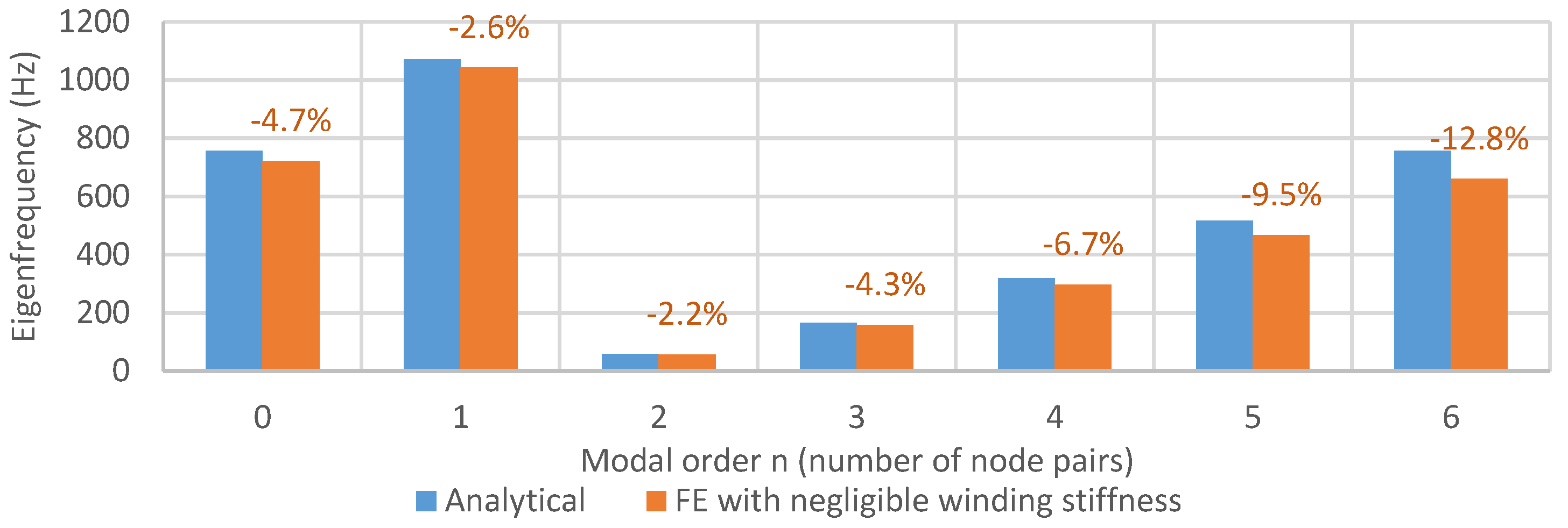
Firstly, the stator including winding was simulated with the analytical and FE models in the same conditions. It means that the stator core material was assumed to be isotropic ( E z = 180 GPa), and the winding Young’s modulus in the FE model was set to a very low value (0.1 GPa), so that it behaved only as additional mass to the system, as also assumed in the analytical model. In this analysis, the stator frame was still not included. The obtained eigenfrequencies for radial mode shapes with uniform axial displacement are shown in Figure 5, where the percentage deviation of the FE model with respect to the analytical model is depicted. In general, two mode shapes in quadrature with each other were found for the same mode order in the FE simulations. However, due to the circumferential symmetry of the cylinder, these two mode shapes presented the same eigenfrequency and therefore, initially, they will not be treated separately.
It can be noticed that the analytical and FE models generated consistent results when compared. In the analytical model, the observed deviations were related to the neglection of the stresses in the radial direction and the neglection of the trapezoidal shape of the elements, due to the simplification of considering a thin cylinder. Furthermore, some geometric details of the stator yoke, such as the holes and slots for the double-dovetail bars shown in Figure 3a, were also not considered in the analytical model and could contribute to the observed deviations.
As a second step, the FE model with an isotropic stator core, still without the frame, was calculated for different values of Young’s modulus of the winding, varying from 0.1 GPa to 67.4 GPa. The results are shown in Figure 6, where the eigenfrequencies in the y-axis are presented as percentage deviation related to the corresponding value predicted by the analytical model for each mode shape. One can observe two distinct behaviors. For the mode orders 0 (also known as the “breathing mode”) and 1, the effect of the winding stiffness was less significant and reached a maximum deviation of approximately 20% in the studied range. For the mode orders 2 to 6, the effect of the winding stiffness was more noticeable and, even for Young’s modulus values as low as 10 GPa, an increase in the range of 30% to 50% was already visible. Additionally, the mode order 2 was more affected than the mode order 3, which was more affected than the mode order 4, and so on, with increasing mode order.
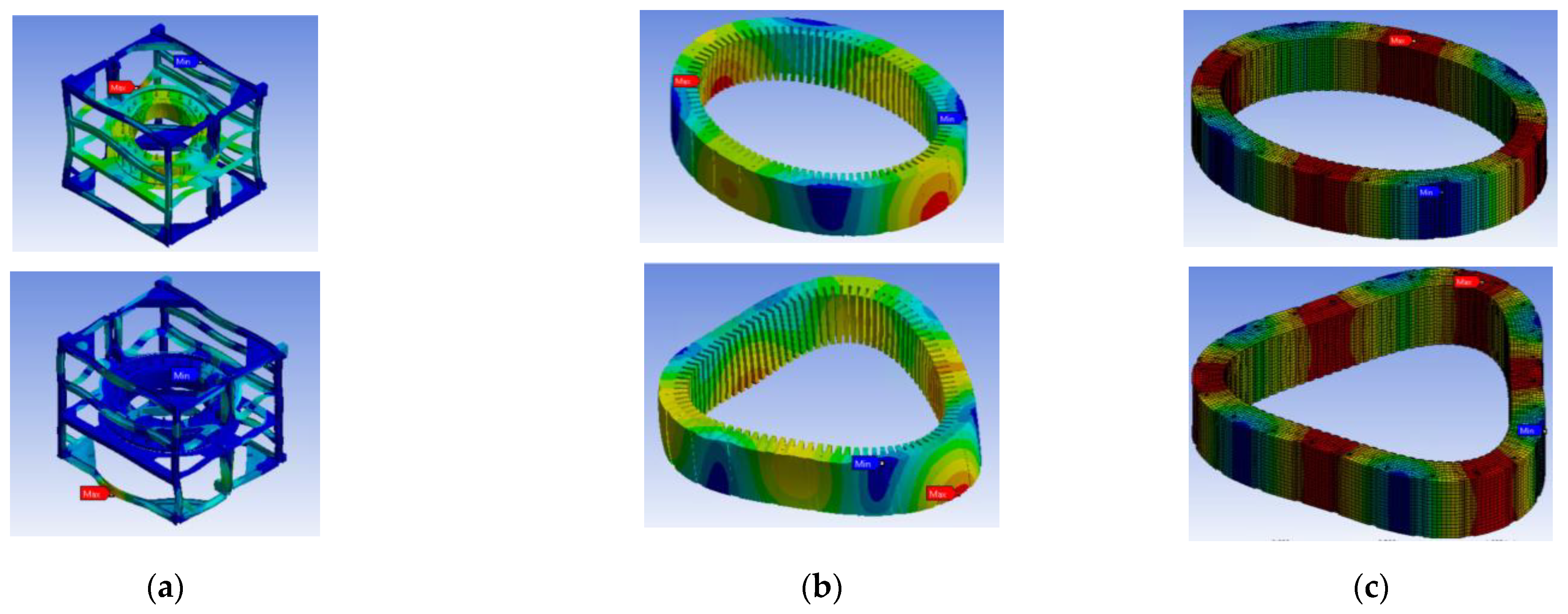
As a third step, the stator frame was included in the FE model. Initially, the winding Young’s modulus and core Young’s modulus in the axial direction were both fixed at 10 GPa, and the contact between core and double-dovetail bars was assumed as frictionless. The results for modes 2 and 3 are shown in Figure 7.
When the frame was included, the mode shapes did not present a perfectly uniform axial distribution anymore, as in the model without the frame (Figure 7b,c). This happened due to the contact between core and pressure fingers at the cylinder axial ends. Furthermore, the circumferential symmetry of a free cylinder was no longer preserved, since the frame was not cylindrically symmetrical. As a consequence, several different eigenfrequencies occurred for the same apparent mode order, instead of only two with the same value, as observed for the model without frame. Some of these modes were dominated by a global displacement of the core, while others were dominated by local eigenfrequencies of the frame structure. They can be distinguished by a detailed visual evaluation of the plotted mode shapes from the FE program.
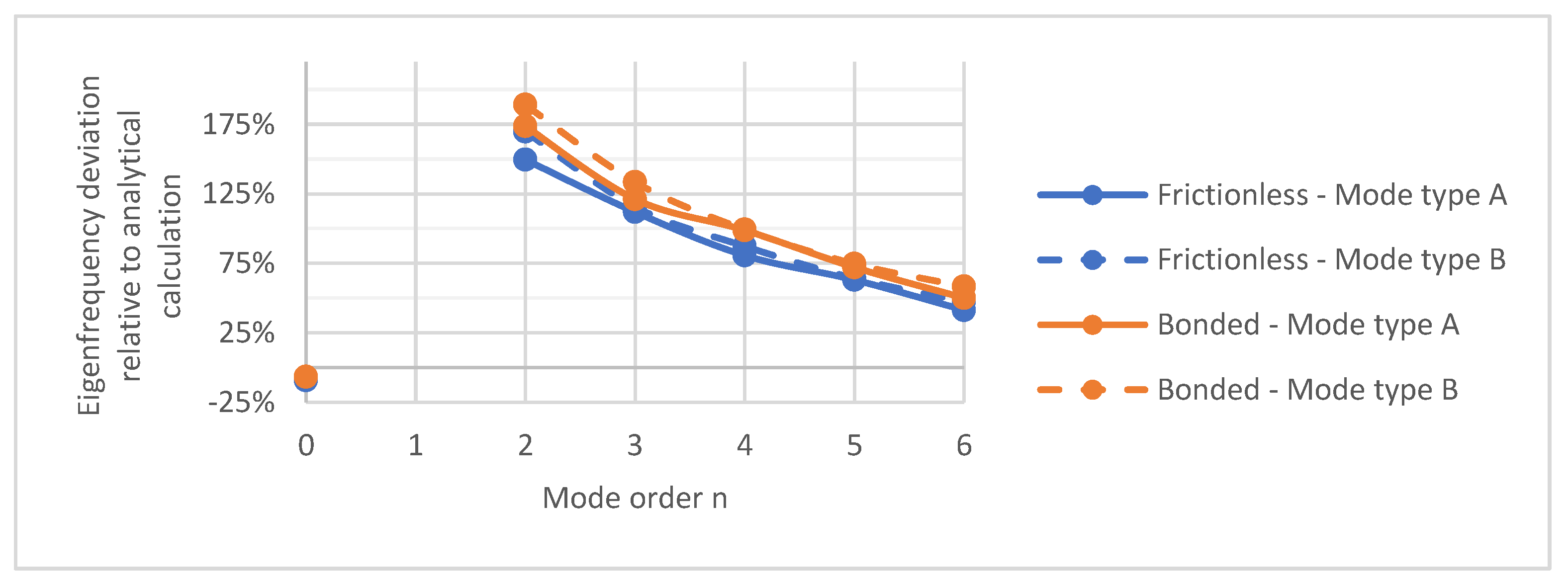
In Figure 8, the eigenfrequencies predicted by the models with bonded and frictionless contact between core and double-dovetail bars are compared for the mode shapes with dominant radial and axially uniform or quasi-uniform displacements. Among the several eigenmodes with same apparent mode order in the stator core, two were selected for evaluation, i.e., those with the most significant core displacement when the eigenmodes were normalized based on the mass matrix [20]. They are referred to as mode types A and B in Figure 8. In the y-axis, the eigenfrequencies are presented as percentage deviation related to the corresponding value predicted by the analytical model for each mode shape.
The mode order 1 depends strongly on the boundary conditions defined for the fixation of the frame on the foundations and was not evaluated in this work. For this reason, the eigenfrequencies for mode order 1 are not included in Figure 8. One can notice that, compared to the analytical model, the eigenfrequency deviation for mode order 2, for example, jumps from approx. 50% (value from Figure 6) to at least 150% when the stator frame is included with frictionless contact between core and double-dovetail bars. If bonded contact is considered, this deviation increases to 174% for the same mode order 2, making then clear the importance of considering the frame in the eigenfrequency calculation. Additionally, the effect of the stator frame was more accentuated for low mode orders, while the deviation value decreased for high mode orders, as observed in Figure 8.
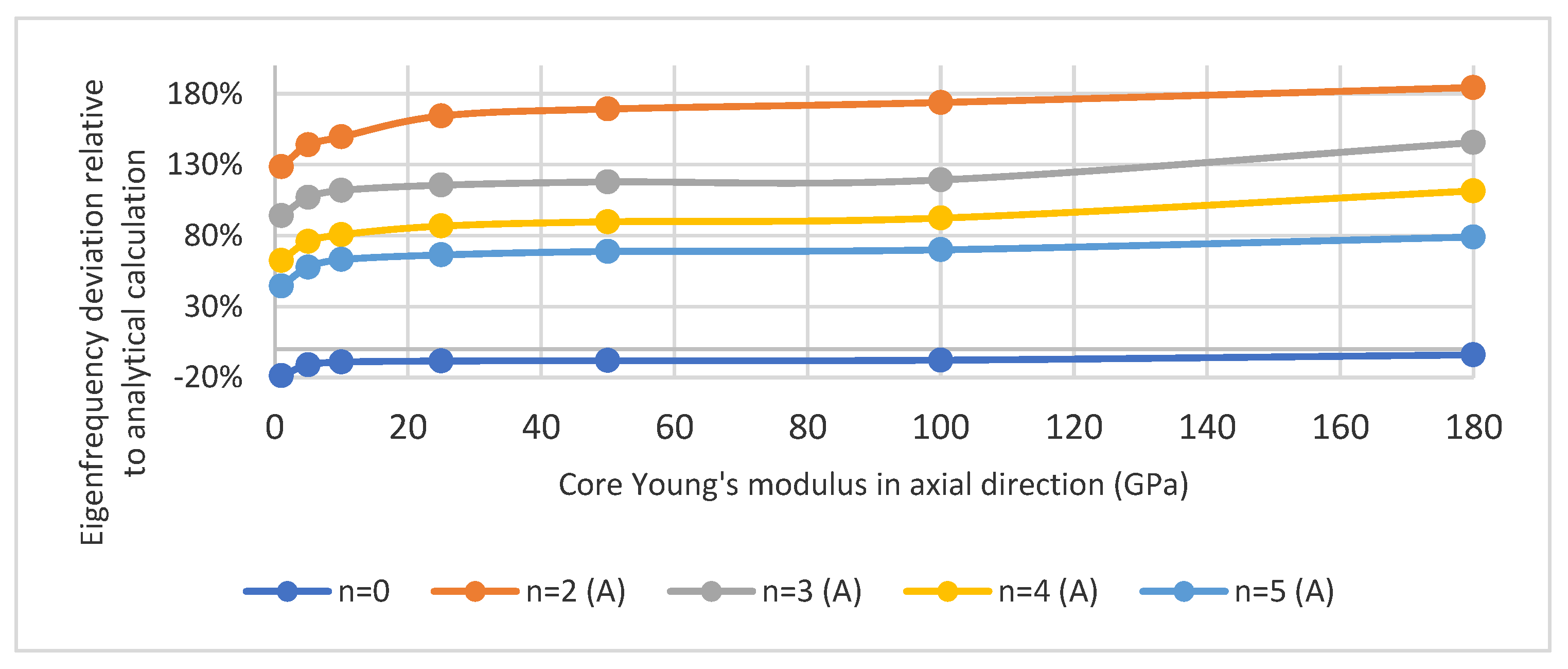
Finally, the effect of core Young’s modulus in the axial direction was investigated, as shown in Figure 9. For that, the winding Young’s modulus was fixed at 10 GPa, frictionless contact between core and double-dovetail bars was assumed, and the core Young’s modulus in the axial direction was varied from 1 GPa to 180 GPa. Only the modes of type A were used for this comparison. In the y-axis, the eigenfrequencies are presented as percentage deviation related to the corresponding value predicted by the analytical model for each mode shape.
For mode order 2, for example, the relative eigenfrequency deviation varied from 128% to 184% in the analyzed range. For higher-mode orders, a similar tendency was observed.

3.2. Experimental Results

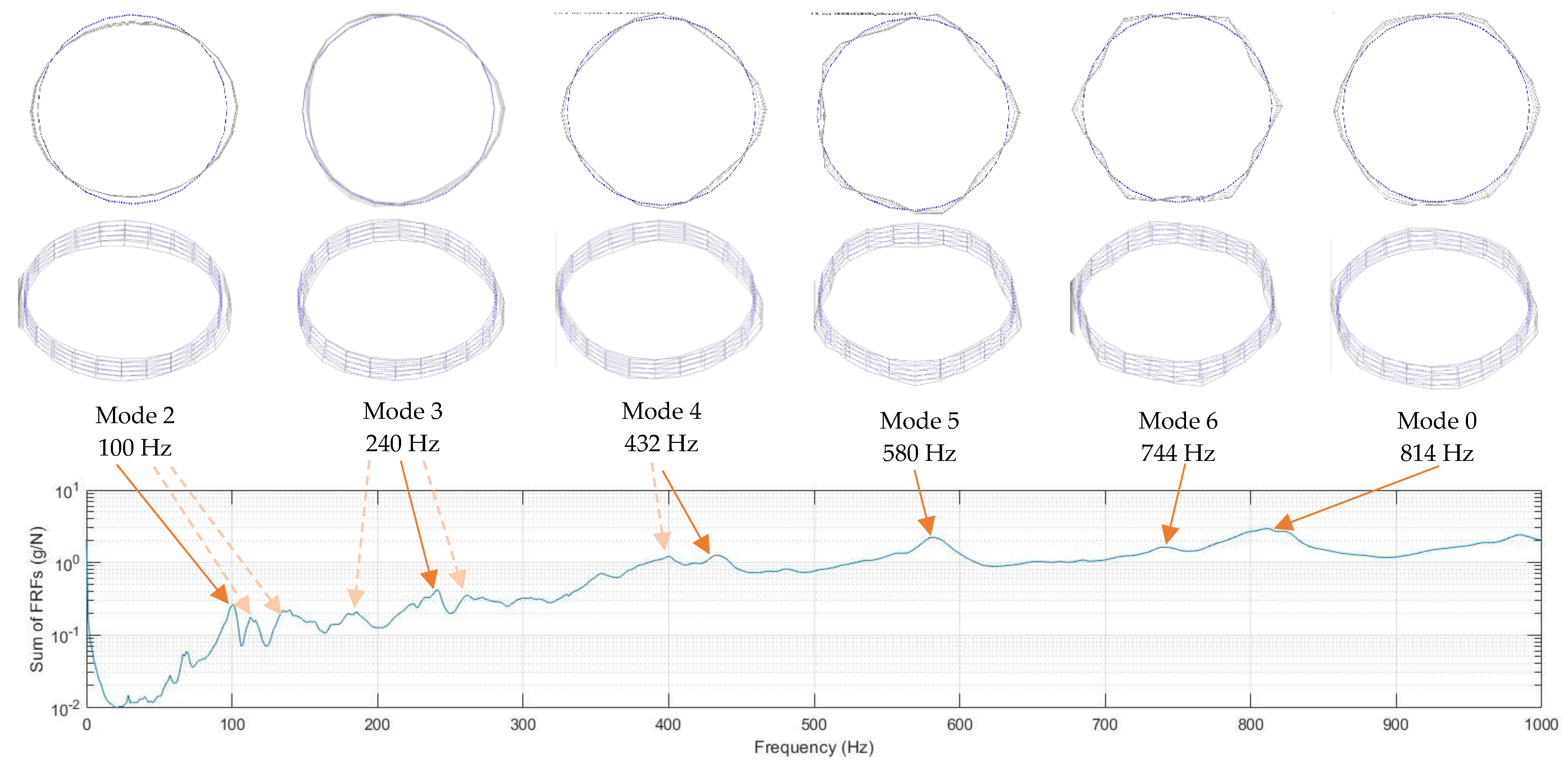
The results from the performed EMA are summarized in Figure 10. The sum of the obtained FRFs absolute values is plotted in the range between 0 and 1 kHz with a frequency resolution of 1.25 Hz, and the relevant eigenmodes for the machine operation are depicted. The eigenfrequencies can be identified by the peaks of the individual FRFs absolute values and were confirmed by their corresponding phase shifts at these points. Since there were multiple FRFs (one for each excited point) and some of them may correspond to a node of a mode shape, the sum of the amplitudes of all obtained FRFs is presented in Figure 10. This was done for the sake of simplicity, instead of showing the amplitude and phase graphs for each of the FRFs. The FRFs were obtained by using the commercial software “m + p Analyser” (version 5.3.0.20979, m + p international Mess- und Rechnertechnik GmbH, Hannover, Germany) for postprocessing the measured time signals. In some cases, multiple eigenfrequencies were identified with similar apparent mode shapes. This was due to the fact that, although no point in the frame structure was directly excited by the hammer, some local modes of the frame could still be indirectly excited and influence the measured acceleration in the stator core. For those cases, the main eigenmode with the highest amplitude in the sum of FRFs is indicated in Figure 10 by a bold solid arrow, while for the other situations, a dashed arrow is used.
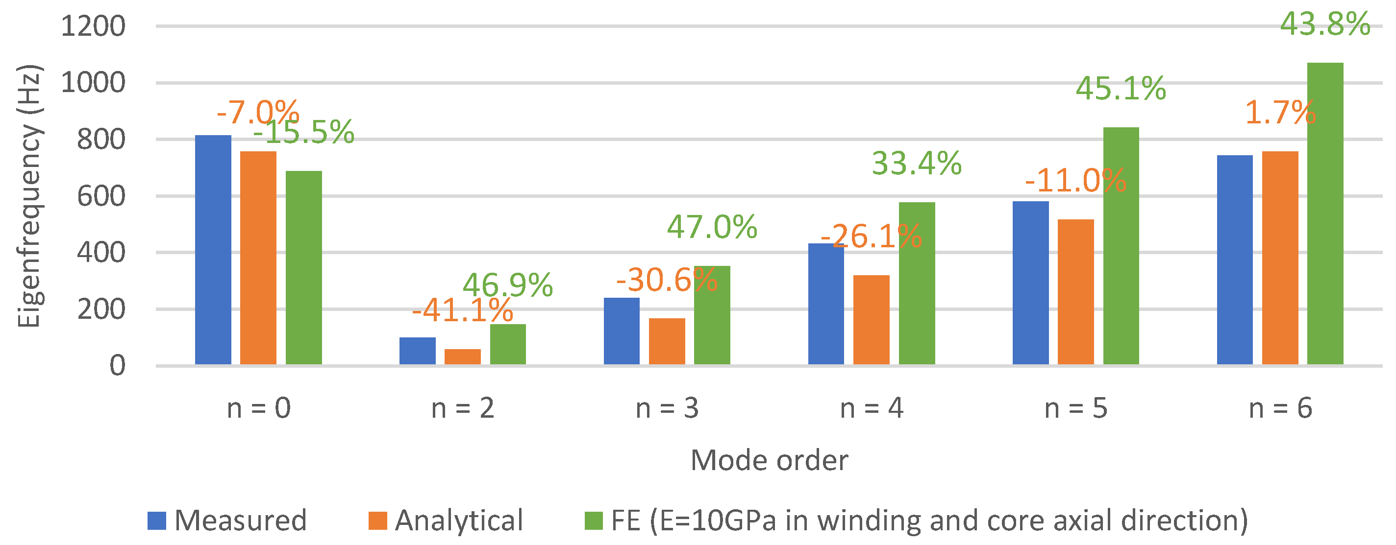
A comparison between the measured eigenfrequencies and the predicted values from the analytical and FE models is represented in Figure 11, where the main modes from Figure 10 (those indicated by a bold solid arrow) are considered. The FE model selected for this comparison was that characterized by a winding Young’s modulus of 10 GPa and a core Young’s modulus in the axial direction of 10 GPa and with frictionless contact between core and double-dovetail bars. The relative deviation of the calculated values with respect to the measurements is also presented in the graph.
In general, the analytical calculation resulted in lower eigenfrequencies than the measurements, since it did not take into account the stiffness of stator winding and frame. On the other hand, the selected FE model showed higher eigenfrequencies than the measurements for n ≥ 2, which is an indication that the winding Young’s modulus and/or core Young’s modulus in the axial direction could have been set to values even lower than 10 GPa. Such values, however, would be considerably far from the rated isolated materials properties (180 GPa for the core lamination and 120 GPa for copper, for example). Although it is theoretically possible, since the equivalent properties incorporate other effects such as lamination stacking, core air ducts, and contact condition of the winding inside the slots, it is recommended to isolate these effects in future works by performing specific material tests on prototypes of one parcel of the stator without the frame, with and without winding. This would bring more accuracy than defining multiple material parameters based on the measured eigenfrequencies of the complete system, where many effects are acting at once. It is important to highlight that the exact values for the material equivalent parameters are still not well defined in the existing literature for hydrogenerators.

4. Discussion and Conclusions

In this work, different models for the calculation of the stator core eigenfrequencies in hydrogenerators were discussed and compared. The analytical model was based on the simplification of a thin cylinder, where stator teeth and winding are considered only as additional mass. The performed FE model without frame and with negligible winding Young’s modulus showed good agreement with the analytical model; however, significant deviations started to appear between the two models when the winding Young’s modulus was increased. As an example, even for Young’s modulus values as low as 10 GPa, an increase in the range of 30% to 50% was already visible for the eigenfrequencies of mode orders 2 to 6 in comparison to the analytical calculation. When the stator frame was included in the FE calculation, even bigger deviations could be observed. The eigenfrequency deviation compared to that of the analytical model for mode order 2, for example, jumped from approx. 50% (value from Figure 6) to at least 150% when the stator frame was included with frictionless contact between core and double-dovetail bars. When assuming a bonded contact, this deviation increased up to 174% for the same mode order 2, making then clear the importance of considering the frame in the eigenfrequency calculation with suitable contact conditions at the interface with the core. Furthermore, it was shown that the core Young’s modulus in the axial direction can significantly affect the results.
For a practical verification of the models, an experimental modal analysis was performed for a prototyped 732 kVA hydrogenerator. The comparison with measured values showed that, in general, the analytical calculation provided lower eigenfrequencies than the measurements, since it did not take into account the stiffness of stator winding and frame. The selected FE model, for comparison, determined 10 GPa for the Young’s modulus in the winding and core in the axial direction, and frictionless contact between core and double-dovetail bars. It showed, in general, higher eigenfrequencies than the measurements, which is an indication that the defined Young’s modulus could have been set to values even lower than 10 GPa. The exact values for the material equivalent parameters are, however, still not well defined in the existing literature for hydrogenerators and need to be deeply investigated in future works. One proposal is to perform specific material tests on prototypes of one parcel of the stator without the frame, with and without winding, where the multiple effects occurring in the complete stator could be isolated from each other. One can highlight that the stator core of these machines is composed of stacked laminations separated in packages by ventilation ducts, which can have a great influence on the system equivalent Young’s modulus in the direction perpendicular to the laminations. Furthermore, the contact of the winding bars with the slot walls may be not perfectly homogeneous due to the winding fixation system, and this should also be investigated in future works.

Author Contributions

Conceptualization, methodology, validation, and writing: A.d.B.; Software and data curation: A.G.; Supervision: A.E. and B.S. All authors have read and agreed to the published version of the manuscript.

Funding

This research received no external funding.

Institutional Review Board Statement

Not applicable.

Informed Consent Statement

Not applicable.

Data Availability Statement

The data presented in this study are contained within the article.

Acknowledgments

The authors acknowledge Voith Hydro for providing the hydrogenerator prototype for validation of the models.

Conflicts of Interest

The authors declare no conflict of interest.

References

  1. De Barros, A.; Chabu, I.E. Modeling of Airgap Flux Density for the Study of Stator Core Vibration in Low Speed Synchronous Machines. COMPEL-Int. J. Comput. Math. Electr. Electron. Eng. 2020, 39, 839–852. [Google Scholar] [CrossRef]
  2. Sobra, J.; Byrtus, M. Impact of Electrical Machine Structural Parts on its Modal and Vibration Behavior. Proceedings of IECON 2019—45th Annual Conference of the IEEE Industrial Electronics Society, Lisbon, Portugal, 14–17 October 2019; pp. 1107–1113. [Google Scholar]
  3. Engevik, E.L. Design and Operation Investigations for Large Converter-Fed Synchronous Machines in Hydropower Applications. Ph.D. Thesis, Norwegian University of Science and Technology, Trondheim, Norway, 2019. [Google Scholar]
  4. Jordan, H. Geräuscharme Elektromotoren; W. Girardet: Essen, Germany, 1950. [Google Scholar]
  5. Arnold, R.N.; Warburton, G.B. Flexural vibrations of the walls of thin cylindrical shells having freely supported ends. Proc. R. Soc. Lond. A Math. Phys. Eng. Sci. 1949, 197, 238–256. [Google Scholar]
  6. White, J.C. The flexural vibrations of thin laminated cylinders. J. Eng. Ind. 1961, 83, 397–402. [Google Scholar] [CrossRef]
  7. Girgis, R.S.; Verma, S.P. Method for accurate determination of resonant frequencies and vibration behaviour of stators of electrical machines. IEE Proc. B (Electr. Power Appl.) 1981, 128, 1–11. [Google Scholar] [CrossRef]
  8. Verma, S.P.; Girgis, R.S. Experimental verification of resonant frequencies and vibration behaviour of stators of electrical machines. Part 1: Models, experimental procedure and apparatus. IEE Proc. B (Electr. Power Appl.) 1981, 128, 12–21. [Google Scholar] [CrossRef]
  9. Verma, S.P.; Girgis, R.S. Experimental verification of resonant frequencies and vibration behaviour of stators of electrical machines. Part 2: Experimental investigations and results. IEE Proc. B (Electr. Power Appl.) 1981, 128, 22–32. [Google Scholar] [CrossRef]
  10. Verma, S.P.; Balan, A. Experimental investigations on the stators of electrical machines in relation to vibration and noise problems. In Proceedings of the IEE Proceedings-Electric Power Applications, Cambridge, UK, 1–3 September 1997; Volume 145, pp. 455–461. [Google Scholar]
  11. Minnier, A.; Gold, B.; Chen, L.; Jahnke, S. Interaction of Generator Rotor/Stator Harmonic Response Under Electromagnetic Forces; Hydrovision: Portland, OR, USA, 2015. [Google Scholar]
  12. Rau, M. Simulation des mechanischen Schwingungsverhaltens von Generatorständern von Wasserkraftanlagen. Master’s Dissertation, Technische Hochschule Ulm, Ulm, Germany, 2016. [Google Scholar]
  13. Zhou, J.; Peng, X.; Li, R.; Xu, Y.; Liu, H.; Chen, D. Experimental and finite element analysis to investigate the vibration of Oblique-Stud stator frame in a large hydropower generator unit. Energies 2017, 10, 2175. [Google Scholar] [CrossRef] [Green Version]
  14. Gerlach, M.E.; Ponick, B. Influence of the Stator Winding and Forming of the End Winding on the Vibration Behavior of Electric Machine’s Stator Core. In Proceedings of the 2020 International Conference on Electrical Machines (ICEM), Gothenburg, Sweden, 23–26 August 2020; pp. 1171–1177. [Google Scholar] [CrossRef]
  15. Yin, H.; Ma, F.; Zhang, X.; Gu, C.; Gao, H.; Wang, Y. Research on Equivalent Material Properties and Modal Analysis Method of Stator System of Permanent Magnet Motor with Concentrated Winding. IEEE Access 2019, 7, 64592–64602. [Google Scholar] [CrossRef]
  16. Chauvicourt, F.; Faria, C.; Desmet, W.; Gyselinck, J.J.C. Transversally Asymmetric Stiffness of Laminated Stator Core: A Solution for Noise Mitigation of Electric Machine. IEEE Trans. Energy Convers. 2019, 34, 613–619. [Google Scholar] [CrossRef]
  17. Garvey, S.D. The vibrational behaviour of laminated components in electrical machines. In Proceedings of the 1989 Fourth International Conference on Electrical Machines and Drives, London, UK, 13–15 September 1989; pp. 226–231. [Google Scholar]
  18. Van der Giet, M.; Kasper, K.; De Doncker, R.W.; Hameyer, K. Material parameters for the structural dynamic simulation of electrical machines. In the Proceedings of the 2012 XXth International Conference on Electrical Machines, Marseille, France, 2–5 September 2012; pp. 2994–3000. [Google Scholar]
  19. Walker, J.H.; Rogers, G.J.; Jackson, R.L. Pressing and clamping laminated cores. Proc. Inst. Electr. Eng. 1964, 111, 565–577. [Google Scholar] [CrossRef]
  20. Braunisch, D.; Ponick, B.; Bramerdorfer, G. Combined Analytical–Numerical Noise Calculation of Electrical Machines Considering Nonsinusoidal Mode Shapes. IEEE Trans. Magn. 2013, 49, 1407–1415. [Google Scholar] [CrossRef]
  21. Cauberghe, B. Applied Frequency-Domain System Identification in the Field of Experimental and Operational Modal Analysis. Ph.D. Thesis, Vrije University Belgium, Brussel, Belgium, 2004. [Google Scholar]
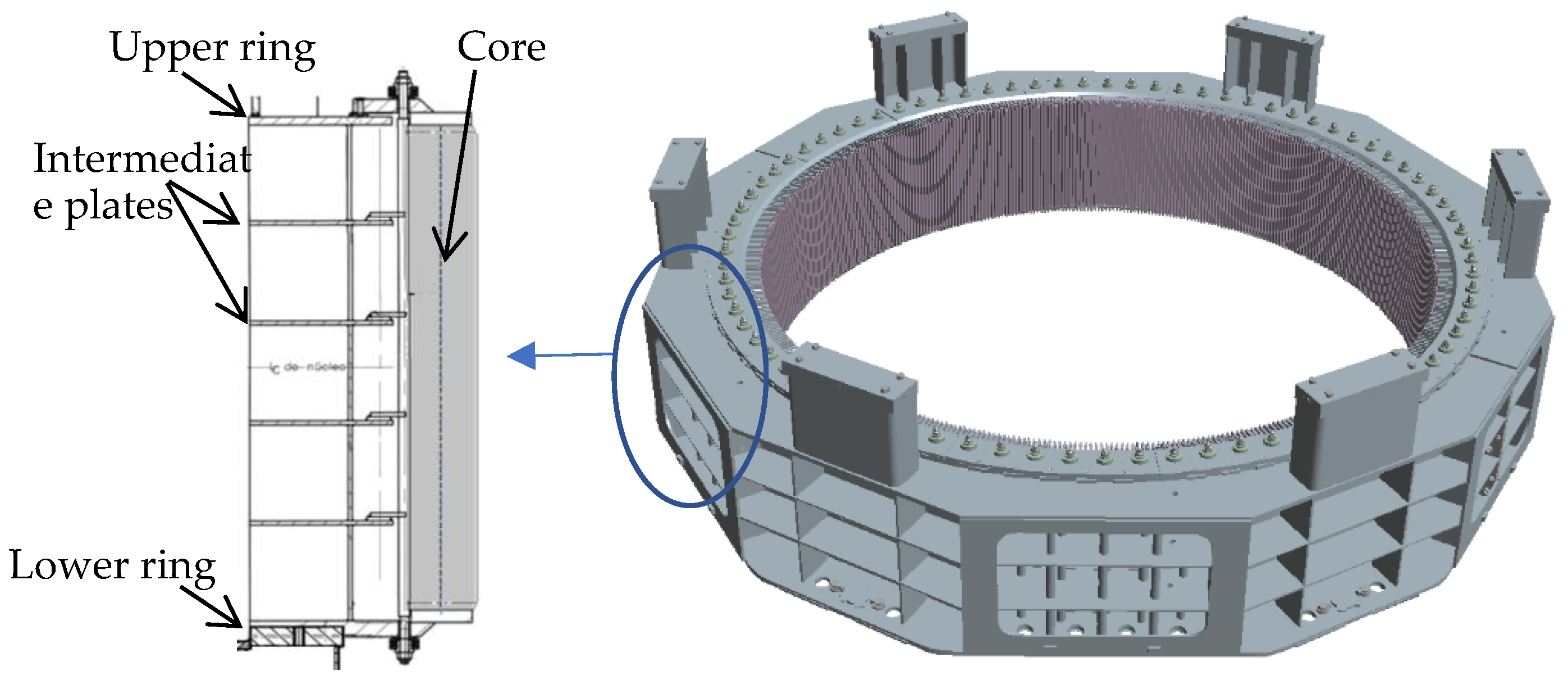
Figure 1. Typical cross section of a hydrogenerator.
Vibration 04 00048 g001
Figure 2. Eigenmodes of a thin cylinder.
Vibration 04 00048 g002
Figure 3. FE model: (a) Stator core and winding; (b) Frame parts replaced by shell elements; (c) Contact between the stator yoke and the double-dovetail bars.
Vibration 04 00048 g003
Figure 4. Tested machine: (a) Installed accelerometer; (b) General view.
Vibration 04 00048 g004
Figure 5. Comparison of analytical and FE models.
Vibration 04 00048 g005
Figure 6. Effect of winding stiffness on FE calculation.
Vibration 04 00048 g006
Figure 7. Calculated mode shapes: (a) General view of mode orders 2 and 3 with frame; (b) Mode orders 2 and 3, hiding the frame from the plot; (c) Mode orders 2 and 3 for the model without the frame.
Vibration 04 00048 g007
Figure 8. Effect of stator frame with bonded and frictionless contact between core and double-dovetail bars.
Vibration 04 00048 g008
Figure 9. Effect of core stiffness in the axial direction on FE calculation with stator frame.
Vibration 04 00048 g009
Figure 10. Results from experimental modal analysis.
Vibration 04 00048 g010
Figure 11. Comparison of the calculation results with the measurements.
Vibration 04 00048 g011
Table 1. Machine main parameters.
ParameterValue
Rated output732 kVA
Rated speed375 rpm
Number of poles16
Number of stator slots96
Stator core outer diameter1640 mm
Stator core total length330 mm
Ventilation ducts11 × 6 mm
Table 2. Material properties.
ParameterCoreWindingFrame
ρ (kg/m³)76007965.57850
E x ,   E y (GPa)1800.1...67.4200
E z (GPa)1...180
G x y (GPa)69.230.04...25.15 176.92
G x z ,   G x z (GPa)0.99...69.23 1
μ x y 0.30.340.3
μ x z ,   μ y z 0.0017...0.3 1
1 Calculated based on defined values of Young’s modulus according to Equations (3)–(5).
Publisher’s Note: MDPI stays neutral with regard to jurisdictional claims in published maps and institutional affiliations.