Article

Contact Force Reconstruction from the Lower-Back Accelerations during Walking on Vibrating Surfaces

by
Jeroen Van Hauwermeiren
1,*,
Katrien Van Nimmen
1,
Benedicte Vanwanseele
2 and
Peter Van den Broeck
1
1
Department of Civil Engineering, Structural Mechanics, KU Leuven, B-3001 Leuven, Belgium
2
Department of Movement Sciences, Human Movement Biomechanics Research Group, KU Leuven, B-3001 Leuven, Belgium
*
Author to whom correspondence should be addressed.
Vibration 2021, 4(1), 205-231; https://doi.org/10.3390/vibration4010015
Submission received: 21 January 2021 / Revised: 17 February 2021 / Accepted: 26 February 2021 / Published: 10 March 2021

Abstract

:
Current models describing the effect of crowd-induced loading require a full-scale validation. To measure the lower-back accelerations during such validation, low-cost accelerometers are used to ensure a sufficient scalability. The goal is to verify to what extent the low-cost sensors can be used for the contact force reconstruction in case the pedestrian walks on a vibrating surface. First, a data set is collected comprising the simultaneous registration of the lower-back accelerations and the contact forces. Three contact force reconstruction methods are presented to accurately reconstruct the contact force in case of walking on a rigid surface. Second, the focus is on the contact force reconstruction in case of walking on a vibrating surface. A numerical study is performed adopting quantities of the Eeklo Benchmark Dataset providing a realistic framework. The additional lower-back accelerations as a result of the vibrating surface are estimated numerically. It is found that directly reconstructing the total contact force leads to inaccurate results. Instead, it is more suited to reconstruct the contact force one would induce on a rigid surface and combine this with an independent model to account for human–structure interaction. The conclusions of this numerical example are case-specific while the presented methodology is generic and can be readily extended to virtually any other structure.

1. Introduction

As a result of ever increasing lighter and stronger materials, footbridge design today is often dominated by its vibrations’ serviceability [1]. Furthermore, human–structure interaction (HSI) effects are more prominent for footbridges with increasing ratios of the crowd mass to the structural mass [2]. The phenomenon of HSI contains all the effects related to the induced loading of a human as a result of the consciously or unconsciously perceived motion on a vibrating surface [3,4]. HSI is usually divided into two sub categories: active and mechanical HSI. Active HSI describes the phenomenon that the walking behavior itself is affected in terms of the walking gait and therefore the induced loads as a result of the perceived structural vibrations. Mechanical HSI comprises the phenomenon that a walking crowd on a footbridge not only induces forces, but also adds stiffness, damping, and mass to the structure. The effect of mechanical HSI can, depending on the properties of the structure and the crowd, highly influence the structural response and is therefore essential to be included in the analysis. Normative design codes neglect the effect of mechanical HSI or only account for the added mass effect [5,6]. This is a result of the absence of full-scale validation of this phenomenon [2]. Such a validation requires detailed information on the loading data during realistic walking scenarios consisting of the simultaneous registration of the induced loads and the structural response [7]. The Eeklo Benchmark Dataset provides, for the first time ever, such a detailed dataset and is thoroughly presented and discussed in [8]. The structural response was registered using a sensor network of tri-axial accelerometers. The trajectories of each pedestrian were registered using a camera setup. The induced loads of the crowd were characterized by registering the acceleration at the lower back of each individual. Given the scale of the application with up to 148 participants, low-cost accelerometers were employed instead of the conventional sensors. Their measurement noise variance is higher compared to their more expensive alternatives. The scope of the present work is to investigate how the employed low-cost sensors can be used to reconstruct the contact forces while specifically accounting for the fact that the pedestrians are walking on a vibrating instead of a rigid surface.
The reconstruction of the vertical contact force using a single accelerometer located at the lower back near the 5th lumbar vertebra (L5) has been extensively investigated in the literature [9,10,11,12,13,14]. When the vertical contact force is reconstructed using a single inertial sensor, it is assumed that that the acceleration coincides with the body center of mass. However, in reality, it has to acknowledged that this assumption is not entirely true as it is close instead of perfectly coinciding with the body center of mass. Denoth et al. [15] proposed an alternative formulation using an apparent mass accounting for the fact that only a fraction of the body center of mass acceleration is registered. The factor was experimentally established in [12,13] and found to be dependent on the walking velocity with values ranging between 0.74 and 0.96. The values were established by applying a least-squares minimization of the reconstructed and measured contact force in the time domain. Therefore, this approach also compensated for modeling errors such as the fact that the apparent body mass changes over the walking cycle. Shahabpoor et al. [12] proposed to replace the constant scaling factor by a time-varying template function spanning one walking cycle which was experimentally trained for a specific test group of participants. All above-mentioned methods employ the magnitude of the registered vertical acceleration to reconstruct the contact force. Therefore, the methods are inapplicable in case one registers the body motion with a sensor or setup for which the registered magnitude shows (significant) differences with the acceleration levels of the body center of mass. This might be the case when a low-cost sensor is employed or when it is placed on top of several layers of clothing. Even in case an accelerometer is placed on the skin, an inherent deviation between true and measured accelerations as a result of the soft-tissue artifact is present [16]. It is noteworthy that these sensitivity errors mainly influence the magnitude, yet the registered quantity is still proportional to the true quantity. Van Nimmen et al. [13,17] recognized this potential problem and developed a contact force reconstruction method that does not rely on the magnitude of the registered body motion. Their method consists of the identification of the consecutive step-by-step frequencies and the application of a single-step model from the literature to reconstruct the contact force. This method is ideally suited either to limit the impact of soft-tissue artefacts, or for applications where low-cost sensors are used (with a sampling rate and/or sensitivity lower than traditional high-end sensors), or even when the sensors are placed at locations other than L5. To this end, the method is ideally suited for identifying the time-variant pacing rates using, for instance, a smartphone.
The study focuses on the contact force reconstruction using the lower-back accelerations registered by a low-cost sensor, both on rigid and vibrating surfaces. First, an experimental data set is collected using an instrumented treadmill where the contact forces are simultaneously collected with the lower back accelerations using the identical low-cost sensors as used in the Eeklo Benchmark Dataset [8]. Two new contact force reconstruction methodologies are presented and are based on the collected data set containing the contact forces and lower back accelerations. Second, the study focuses on the contact force reconstruction on vibrating surfaces. The human body is a dynamic system that moves forward by the extension and contraction of the muscles, resulting in the kinetics of the body. In case the human body moves over a vibrating surface, the body kinetics are influenced by the transmission of these perceived vibrations as a result of mechanical HSI. It is virtually unverified to what extent contact force reconstruction techniques can be applied in case the body motion is registered when a pedestrian is walking on a vibrating surface. It is numerically investigated how the human body motion is affected in case of walking on a vibrating surface as a result of mechanical HSI. The additional human body accelerations are numerically estimated by modeling the human body dynamics by a spring–mass–damper system, which is a popular modeling strategy for the effect of mechanical HSI [2,11,18,19,20]. A numerical study is performed to assess the reconstructed structural response using on one hand the measured contact forces and on the other hand the reconstructed contact forces using the total lower-back accelerations. The latter are the combination of the registered ones combined with the additional numerically estimated human body accelerations as a result of the mechanical HSI phenomenon. To obtain a realistic simulation scenario, the considered structure is the Eeklo footbridge, and the flow is adopted from one of the experiments as presented in the Eeklo Benchmark Dataset [8].
The remainder of the text is organized as follows: Section 2 introduces the human body dynamics in rigid and vibrating-surface conditions and the dynamics of the coupled crowd-structure system. Then, Section 3 presents the measurement campaign in the laboratory using the instrumented treadmill allowing for the simultaneous registration of contact forces and lower back accelerations. Two new and one existing contact force reconstruction methodology are presented and assessed using the established data set. In Section 4, it is discussed how the reconstruction methodologies can be applied in case the pedestrian walks on a vibrating surface. The paper concludes by summarizing the most important conclusions in Section 5.

2. Dynamics Coupled Crowd-Structure System

2.1. Human Body Dynamics

The human body is in reality composed of a large number of body segments [21]. It is common practice to lump all the driven masses in one single driven mass m H 1 and all the non-driven masses into a single non-driven mass m H 0 [19,22,23]. Obviously, the sum equals the body weight of the pedestrian: m ped = m H 0 + m H 1 . The driven mass m H 1 is driven by an internal driving term G ( t ) , while the connection between the non-driven mass m H 0 and driven mass m H 1 is modeled by an internal reaction force G ( t ) (Figure 1a).
Expression of the force equilibrium at the contact plane and applying Newton’s second law gives:
F ( t ) = m H 0 u ¨ s ( t ) + m H 1 u ¨ H 1 ( t ) = ( 1 μ H 1 ) m ped u ¨ s ( t ) + μ H 1 m ped u ¨ H 1 ( t )
where F ( t ) is called the contact force and μ H 1 = m H 1 / m ped the ratio of the driven mass to the total mass of the pedestrian.
In case of walking on a rigid surface, the kinetics of the supporting surface are zero ( u s ( t ) = 0 ) yielding the following simplifications: G ( t ) = G RS ( t ) , F ( t ) = F G ( t ) = F RS ( t ) and u H 1 ( t ) = u H 1 RS ( t ) , where the subscript RS denotes that it concerns rigid-surface conditions. The contact force in this case reads:
F RS ( t ) = m H 1 u ¨ H 1 RS ( t ) = μ H 1 m ped u ¨ H 1 RS ( t )
For walking on vibrating surfaces, it is obvious that u s ( t ) 0 . In this study, it is assumed that the internal driving term G ( t ) is unaltered with respect to the rigid-surface conditions: G ( t ) = G RS ( t ) . This corresponds to the assumption that there is no active human–structure interaction. Moreover, in case of walking on vibrating surfaces, the human body kinetics do not only consist of the internally-driven kinetics u H 1 RS ( t ) but an additional mechanical interaction term u H 1 int ( t ) , resulting from the mechanical interaction of the human body with the vibrating surface. In this study, it is assumed that the superposition principle holds i.e., u H 1 tot ( t ) = u H 1 RS ( t ) + u H 1 int ( t ) . Combining the total human body kinetics with Equation (1) allows for writing the contact force in the following form:
F tot ( t ) = m H 1 u ¨ H 1 RS ( t ) = F RS ( t ) + m H 0 u ¨ s ( t ) = F H 0 int ( t ) + m H 1 u ¨ H 1 int ( t ) = F H 1 int ( t ) = F int ( t )
and illustrates how the total contact force ( F tot ( t ) ) is the combination of the internally-driven contact force equal to the contact force on a rigid surface ( F RS ( t ) ) and an additional mechanical interaction contact force ( F int ( t ) ).

2.2. Equations of Motion of the Coupled Crowd-Structure System

The structural response to the walking excitation of a crowd composed of n p pedestrians is calculated using the well-known equations of motions in modal coordinates of the reduced-order finite element (FE) model:
Z ¨ ( t ) + Γ Z ˙ ( t ) + Ω 2 Z ( t ) = Φ T S p ( t ) F tot ( t ) = Φ T S p ( t ) F RS ( t ) + F int ( t )
where Z ( t ) R n m are the modal displacements of the n m retained modes, Ω 2 R n m × n m a diagonal matrix containing the squared circular eigenfrequencies in increasing order, Γ R n m × n m a diagonal matrix containing the elements 2 ξ j ω j at row and column j with ξ j the modal damping ratio and ω j the circular eigenfrequency of mode j. The matrix Φ R n DOF × n m contains the corresponding mode shape values at each degree of freedom (DOF) of the structure as columns, S p ( t ) R n DOF × n p is the force-selection matrix containing the time-varying position of the n p pedestrians and thus relating each position to a corresponding degree of freedom of the system, F tot ( t ) R n p is the matrix containing the total contact force of each pedestrian, which is the combination of the internally-driven contact forces F RS ( t ) R n p and the mechanical interaction contact forces F int ( t ) R n p .
As the interaction contact forces depend on the perceived vibrations, it is convenient to place F int ( t ) on the left-hand side of Equation (4), allowing for a closed-form solution of the structural response. To this end, it is necessary to make an assumption on how the internal reaction force G ( t ) is modeled. A popular approach is to model the connection of the driven mass m H 1 with the non-driven mass m H 0 moving with the supporting surface by a linear spring and linear viscous damper (Figure 1b) [2,11,18,19]. The internal reaction force reads: G ( t ) = c H 1 [ u ˙ s ( t ) u ˙ H 1 ( t ) ] + k H 1 [ u s ( t ) u H 1 ( t ) ] where k H 1 and c H 1 respectively denote the spring and damping coefficient. The operator is linear in this case. The spring–mass–damper is often characterized in terms of its natural frequency f H 1 and damping ratio ξ H 1 [2]. Equation (4) is rewritten to:
M HB ( t ) Z ¨ ( t ) U ¨ H 1 int ( t ) + C HB ( t ) Z ˙ ( t ) U ˙ H 1 int ( t ) + K HB ( t ) Z ( t ) U H 1 int ( t ) = Φ T S p ( t ) F RS ( t ) 0
where M HB ( t ) , C HB ( t ) and K HB ( t ) are the system matrices of the coupled crowd-structure system. Their derivation and definition are given in [2]. For a certain loading scenario ( S p ( t ) and F RS ( t ) ), Equation (5) is solved for the response of the coupled crowd-structure system ( Z ¨ ( t ) U ¨ H 1 int ( t ) T ) using a discrete-time state space approach [2].

3. Contact Force Reconstruction on Rigid Surfaces

3.1. Overview of Measurement Setup and Experiments

In total, 15 healthy Belgian adults (age: 21–51 years, weight: 54–85 kg, height: 1.66–1.90 m, females: 2, males: 13, Table 1) participated in the experimental program in the Movement and posture Analysis Laboratory Leuven at the Department of Movement Sciences of KU Leuven [24]. The participants signed an informed consent in accordance with the ethical guidelines for research involving human participants at KU Leuven.
An instrumented treadmill with two separate belts (Forcelink) was used to register the tri-axial contact forces with a sampling rate of 1 kHz. The instrumented treadmill is considered to correspond to a rigid surface. The study in [17] compared the contact forces registered using either the instrumented treadmill or a force plate embedded in the floor (type AMTI) and thus perfectly rigid. Comparison of the registered contact forces revealed that there is no significant difference between the patterns of the two registered quantities.
Each participant performed three tests with each a different treadmill (walking) speed (Table 1). The walking speeds were randomized to avoid a bias due to fatigue or psychological adaptation of the walking gait. Each test duration is approximately two minutes. The first 15 s are considered to be the time to adapt to the walking speed of the treadmill, and are removed in the further analysis. The test results of pedestrian 7, trial 1 and pedestrian 12, trial 1 are discarded due to errors in the data registration.
In addition to the contact force, the 3D body acceleration of each participant was registered at the lower back (L5). The employed sensor is the low-cost tri-axial USB accelerometer of the type GCDC X-16D and is identical to the one used during the collection of the Eeklo Footbridge Benchmark Dataset [8]. The sensors were placed on top of the jacket of each participant. This is similar to the Eeklo Footbridge Benchmark Dataset, where every individual wore a jacket. In addition to the low-cost accelerometers, the body motion was measured using visual markers in combination with a 10-camera Vicon motion capture system [25] with a sampling frequency of 200 Hz. The Vicon system was calibrated prior to the first experiment. The visual markers were placed on the low-cost accelerometers. The accelerations of the visuals markers are calculated based on the trajectories by applying a central second-order finite differencing.
First, the force plate data are decimated to 200 Hz. To mitigate the effect of measurement noise, all signals are low-pass filtered using a 4th order Butterworth filter with a cutoff frequency of 12 Hz. As such, the relevant frequency content (0–10 Hz) for the vibration serviceability assessment of footbridges (scope of application) is retained [4]. The visual marker and force plate data are synchronously registered. The data from the low-cost accelerometers are synchronized with the visual marker and force plate data by maximizing the cross correlation between the accelerometer data and the derived accelerations of the visual marker data. In the remainder of this paper, only the (synchronized) accelerations registered by the low-cost sensors are used.
Figure 2 illustrates a typical time series and amplitude spectrum of the registered contact force, corresponding to participant 2 during trial 2, hereafter referred to as the reference trial. The frequency content of the contact force is narrow banded and consists of multiple main and subharmonics. The power leakage around the main harmonics and the occurrence of sub harmonic components are a result of the imperfect walking behavior, as reported in [26]. Additionally, Figure 3 shows the time series and amplitude spectrum of the vertical L5 acceleration of the reference trial. The narrow-banded nature is also observed for the L5 acceleration.
The average step frequency f s , av is obtained as the abscissa corresponding to the maximum value of the power spectral density (PSD) of the contact force or lower-back acceleration, as proposed in [13]. Welch’s method is used and estimates the PSD by consecutively dividing the signal into overlapping segments followed by a windowing and calculation of the periodogram of each segment. Then, the PSD estimate is obtained by averaging the squared periodogram over all segments. The method is ideally suited to estimate the PSD based on a measured time series of the signal and is illustrated in Figure 4a for the reference trial. The PSD is estimated practically using Welch’s method (pwelch command of Matlab R2016b [27]) employing a Gaussian window with a duration of 10 s and a 50% overlap between consecutive segments. Figure 4b shows the histogram of the average step frequency for all trials, thus containing different walking speeds. The distribution has a Gaussian shape with a mean value of 1.97 Hz and a standard deviation of 0.10 Hz.

Quantification of the Measurement Noise

The X16-1D uses the Analog Devices ADXL345 3-axis digital accelerometer sensor (ADI, Wilmongton, MA, USA), which is based on micro-electro-mechanical semiconductor technology (MEMS) [28]. While the employed sensors use built-in oversampling algorithms and signal filters minimizing the effects of sensor noise [28], the measurements are inevitably subjected to noise. It is assumed that the noise is additive, meaning that it is uncorrelated to the true acceleration. In order to determine the measurement noise characteristics, a set of 12 sensors was selected and were placed on a rigid floor for 21 h. A detrend with constant coefficient is applied to remove the static gravity component. The measurement noise is modeled as bandpass-limited white noise. The modeling choice is inspired by the observation that the autocorrelation resembles the Dirac delta function while the PSD is nearly flat up to 70 Hz. The variance is calculated for all sensors and directions. The histogram (Figure 5a) shows that the distribution tends to decrease while its cumulative distribution (Figure 5b) indicates a 95% value of 0.0124 ( m / s 2 ) 2 , which is used through the rest of the work. The body motion in a controlled environment is often registered using the Xsens MTw Development Kit measurement system [29], as was for instance done in [13,17]. According to the technical data sheet [29], the measurement noise variance is 0.000693 ( m / s 2 ) 2 , which is approximately 18 times lower than the measurement noise of the X16-1D. When calculating the signal-to-noise ratio (SNR) of a signal registered by the low-cost accelerometer (X16-1D), it is taken into account that the signal is low-pass filtered with a cutoff frequency of 12 Hz. In other words, the denominator in the calculation of the SNR is 0.0124 ( m / s 2 ) 2 / Hz × 12 Hz/70 Hz. The registered L5 acceleration of the reference trial (Figure 3) has an SNR of 3449 (≈35.6 dB). This high value suggests that the low-cost sensors are suited for the contact force reconstruction.

3.2. Decomposition and Normalization of the Signals

Given their narrow-banded nature, the registered quantities (L5 acceleration and contact force) are approximated as the summation of a static component and n h main and n h s subharmonic contributions. The harmonic contributions are obtained by applying a 4th order Butterworth filter with lower and upper cutoff frequencies f m L and f m U for the main harmonics, and f m L , s and f m U , s for the sub harmonics are used. The values are adopted from [26], which is [ m 0.25 , m + 0.25 ] f s , av for main harmonic m and [ m 0.75 , m 0.25 ] f s , av for sub harmonic m. Typically, the number of main and sub harmonics is limited to 5. This decomposition was initially proposed by Živanović et al. [26]. The contact force and L5 accelerations are written as:
F ( t ) F filt ( t ) = G + m = 1 n h F m ( t ) + m = 1 n h s F m s ( t )
u ¨ L 5 ( t ) u ¨ L 5 filt ( t ) = g + m = 1 n h u ¨ L 5 , m ( t ) main harmonics + m = 1 n h s u ¨ L 5 , m s ( t ) sub harmonics
where F ( t ) is the contact force, u ¨ L 5 ( t ) is the vertical body acceleration at L5. F m ( s ) ( t ) and u ¨ L 5 , m ( s ) ( t ) are the main (sub) harmonic components of the contact force and the L5 acceleration, and are obtained by applying a bandpass filter. The approximation signs stem from the errors obtained by applying the bandpass filter but is found to be small and neglected in the further analysis.
Once the signal is decomposed into its harmonic components, each harmonic component is written as the product of a normalized signal with a power equal to a sine wave with unit amplitude and a power-scaling factor. This representation will prove useful for the contact force reconstruction. The main (sub) harmonic components of the contact force and L5 acceleration are written as:
F m ( s ) ( t ) = G DLF m ( s ) F m ( s ) ( t )
u ¨ L 5 , m ( s ) ( t ) = g DAF m ( s ) u ¨ L 5 , m ( s ) ( t )
where G and g respectively denote the body weight of the pedestrian and the gravity constant (=9.81 m/s2). The abbreviations DLF and DAF respectively denote Dynamic Loading and Acceleration Factor. The quantities F m ( s ) ( t ) and u ¨ L 5 , m ( s ) ( t ) respectively are the normalized main (sub) harmonic components of the contact force and L5 acceleration.
The normalized signals satisfy 1 T 0 T | F m ( s ) ( t ) | 2 d t = 1 2 and 1 T 0 T | u ¨ L 5 , m ( s ) ( t ) | 2 d t = 1 2 , so that the power of these signals equals 1 2 , the power of a unit-amplitude sine wave. Expressing this using Equations (8) and (9) allows for obtaining the values of the DLFs and DAFs as follows:
DLF m ( s ) = 2 G 1 T 0 T | F m ( s ) ( t ) | 2 d t
DAF m ( s ) = 2 g 1 T 0 T | u ¨ L 5 , m ( s ) ( t ) | 2 d t

3.3. Modeling the Relation between the Contact Force and the L5 Acceleration

The way the contact force is conventionally reconstructed (Section 1) is motivated by the strong correlation between the contact force and the acceleration at L5. While the conventional reconstruction methods assume a constant proportional factor between the two quantities, the relation here is instead modeled using a transfer function h ( t ) relating the weight-normalized dynamical part of the contact force and gravity-normalized dynamical part of the L5 acceleration. The relation between contact force and L5 acceleration using the transfer function formally reads:
F ( t ) G G = h ( t ) u ¨ L 5 ( t ) g g
The use of a transfer function allows for a more sophisticated reconstruction rather than employing a single scaling constant. Moreover, the narrow-banded nature of both signals (Figure 2) is accounted for by simplifying the transfer function to the following form:
m = 1 n h F m ( t ) G + m = 1 n h s F m s ( t ) G m = 1 n h h m u ¨ L 5 , m ( t τ m ) g + m = 1 n h s h m s u ¨ L 5 , m s ( t τ m s ) g
m = 1 n h DLF m F m ( t ) + m = 1 n h s DLF m s F m s ( t ) m = 1 n h h m DAF m u ¨ L 5 , m ( t τ m ) + m = 1 n h s h m s DAF m s u ¨ L 5 , m s ( t τ m s )
where the transfer function is now characterized by a magnitude (amplitude ratio) h m ( s ) and a phase shift τ m ( s ) for each main (sub) harmonic m. In fact, this way of modeling assumes that the harmonic component m of the contact force can be reconstructed by shifting the harmonic component m of the L5 acceleration and rescaling its power content. The magnitude of main (sub) harmonic component m is estimated as h m ( s ) = DLF m ( s ) / DAF m ( s ) . The phase shift τ m ( s ) corresponds to the value which maximizes the cross correlation between F m ( s ) ( t ) and u ¨ L 5 , m ( s ) ( t τ m ( s ) ) . The corresponding phase angle is found as θ m = 2 π m f s , av τ m and θ m s = 2 π ( m 0.5 ) f s , av τ m s in case of the main and sub harmonics, respectively. The approximation signs in Equations (13) and (14) arise from the fact that a simplified form of the transfer function is employed. The specific form of the transfer function results in the absence of poles.
The estimated transfer function of the reference trial (Figure 6) shows that the values are indeed frequency dependent (harmonic number), both for the magnitude and phase angle. Additionally, the time dependence of the transfer function for the reference trial is examined. The transfer function characteristics as a function of time are calculated by considering a sliding window (length 20 s). Analysis shows that, for all harmonics components, the transfer function quantities are nearly constant over time. Therefore, the transfer function characteristics are considered to be time-invariant in the further analysis.
The procedure is applied for every trial. The empirical distribution of the transfer function components approximates a Gaussian (first three main harmonic components shown in Figure 7). The results of all trials are combined into a single stochastic transfer function. Each harmonic is now represented by a mean value and 95% confidence value, calculated as mean ± 2 × the standard deviation (Figure 8). The averaged transfer function is denoted as h ¯ ( t ) and consists of the averaged magnitudes h ¯ m ( s ) and averaged phase angles θ ¯ m ( s ) , corresponding to the mean value of the stochastic transfer function (Figure 8). The magnitude of the transfer function of the first harmonic (Figure 8a) is nearly one with a relatively low scatter. For the higher harmonics, the values are on average 0.5 and a relative high scatter with values comprised between 0.25 and 1.5. The phase values of the transfer function (Figure 8b) for the first main harmonic are all nearly zero with low scatter. The second and third main harmonic are also zero mean with a scatter comprised between π / 4 and π / 4 . The fourth and fifth main harmonic exhibit a larger scatter comprised between π / 2 and π / 2 and are nearly zero mean. Analysis shows that the correlation between the components of the transfer function and the average step frequency is weak ( | Correlation coefficient | 0.30 ). Therefore, the relation between the magnitude of the transfer function and the average step frequency is not further considered.

3.4. Contact Force Reconstruction Based on the Registered L5 Acceleration Using the Averaged Transfer Function

It is often not possible to establish an individual transfer function for every participant. Instead, an averaged transfer function h ¯ ( t ) is used that is estimated based on a representative group of participants. The averaged transfer function is previously established in a laboratory setting (Section 3.3).
This paragraph presents three reconstruction methods (RMs) to reconstruct the contact force based on the registered L5 accelerations. The different RMs combine different degrees of information of the registered L5 accelerations, the averaged experimentally established transfer function (Section 3.3) and information provided by literature contact force models.

3.4.1. Reconstruction Method I

RM I employs the averaged transfer function to reconstruct the contact force F ˜ I ( t ) based on the registered accelerations u ¨ L 5 ( t ) . As such, the reconstructed contact force using RM I reads:
F ˜ I ( t ) = G + m = 1 n h G h ¯ m DAF m u ¨ L 5 , m ( t ( 2 π m f s , av ) 1 θ ¯ m ) = DLF ˜ m = F ˜ I , m ( t ) u ¨ L 5 , m ( t ( 2 π m f s , av ) 1 θ ¯ m ) = F ˜ I , m ( t ) = F ˜ I , m ( t ) + m = 1 n h s G u ¨ L 5 , m s ( t ( 2 π ( m 0.5 ) f s , av ) 1 θ ¯ m s ) ) h ¯ m s DAF m s = DLF ˜ m s = F ˜ I , m s ( t ) u ¨ L 5 , m s ( t ( 2 π ( m 0.5 ) f s , av ) 1 θ ¯ m s ) ) = F ˜ I , m s ( t ) = F ˜ I , m s ( t )
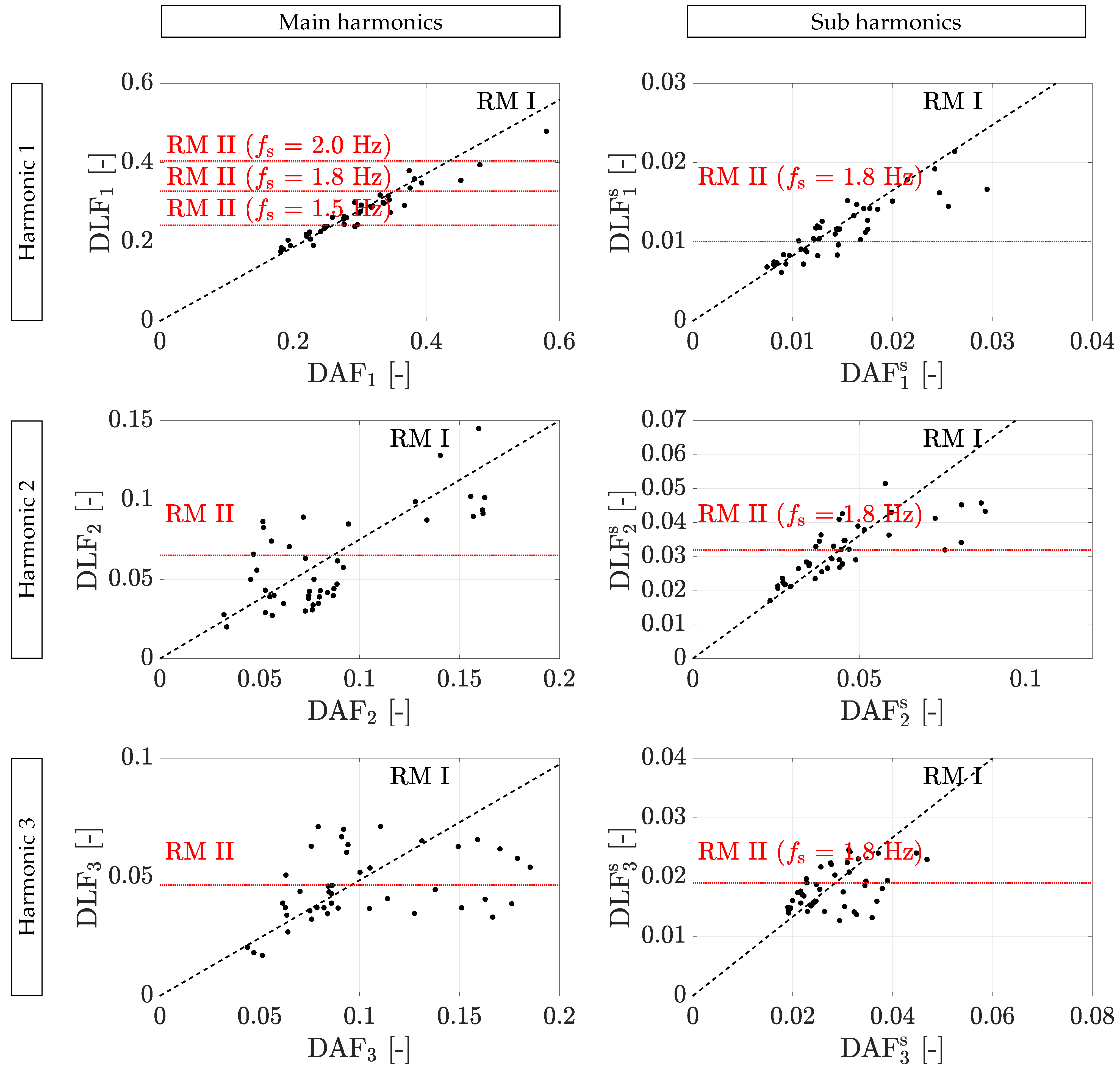
where F ˜ I ( t ) denotes the reconstructed force and h ¯ ( t ) the averaged transfer function.This representation clearly shows that the reconstructed harmonic force component F ˜ I , m ( s ) ( t ) is the combination of the reconstructed power content of the force, DLF ˜ m ( s ) , and the reconstructed normalized force F ˜ I , m ( s ) ( t ) . RM I uses both the registered power ( DAF m ( s ) ) and the normalized registered L5 acceleration ( u ¨ L 5 , m ( s ) ( t ) ). The power content of the reconstructed force ( DLF ˜ m ( s ) ) is estimated based on the power content at the lower back ( DAF m ( s ) ). This is possible because the two quantities are correlated. Table 2 lists the correlation coefficient between between the DAF and DLF for each main and sub harmonic component. For the calculation of the correlation coefficient, the data of all trials are considered. The first main harmonic has a very strong correlation (correlation coefficient > 0.90). The other harmonics have a lower correlation which tends to decrease with the harmonic number. The statistical scatter is a combined effect of the measurement noise and the inherent variability amongst pedestrians and trials. Incorporation of the existing correlation between the power of the L5 acceleration and the contact force through the magnitude of the transfer has the advantage that the inter-person variability in DLFs is accounted for.

3.4.2. Reconstruction Method II

Sometimes, it is impossible to rely on the power of the registered accelerations while the registered quantity is still proportional to the true one. A possible cause is the presence of severe soft tissue artifacts e.g., sensors placed on several layers of clothing. One can opt to use the transfer function to reconstruct the normalized contact force while using a pre-defined value for its power content (DLF). Such pre-defined DLFs can, for instance, be adopted from the literature in case the group size is large or previously elaborated measurements for a specific small-size test group of participants. The formal methodology of RM II reads:
F ˜ II ( t ) = G + m = 1 n h G DLF ¯ m u ¨ L 5 , m ( t ( 2 π m f s , av ) 1 θ ¯ m ) = F ˜ II , m ( t ) = F ˜ II , m ( t ) + m = 1 n h s G DLF ¯ m s u ¨ L 5 , m s ( t ( 2 π ( m 0.5 ) f s , av ) 1 θ ¯ m s ) ) = F ˜ II , m s ( t ) = F ˜ II , m s ( t )
where DLF ¯ m ( s ) contains the pre-defined power content of the reconstructed contact forces, and the bar denotes that it concerns a pre-defined quantity.
The DLFs as proposed by Živanović et al. [26] are shown in Figure 9 for each harmonic. This representation shows how the DLFs are independent of the registered DAFs in the case of RM II, while RM I exploits the measured DAFs and its correlation with the DLFs. Furthermore, it is noteworthy that the reconstructed normalized contact force of RM I and RM II are identical since the same averaged transfer function h ¯ ( t ) is used: F ˜ I , m ( s ) ( t ) = F ˜ II , m ( s ) ( t ) . One of the consequences of this approach is that all pedestrians possess an equal power for each harmonic, with the exception of the fundamental main harmonic as this depends on the average step frequency (Figure 9). In other words, the inter-person variability in DLFs is disregarded using this reconstruction approach.

3.4.3. Reconstruction Method III

In some cases, even the normalized L5 acceleration is not a relevant measure to reconstruct the normalized contact force. This is the case when one uses sensors with a low signal-to-noise ratio or irregular sampling rate. Other cases constitute the situation where the sensor is not placed at L5, ill positioned, too many layers of clothing are present or the sensor is not securely fixed to the human body. A methodology to reconstruct the contact force in such case is provided in [13,17]. The normalized L5 acceleration of the first harmonic ( u ¨ L 5 , m = 1 ( t ) ) is used to reconstruct the contact force F ˜ III ( t ) . The methodology is a two-step process where first the time of the consecutive footfalls is determined as the dips or peaks in the normalized first harmonic of the L5 acceleration, followed by a contact force reconstruction using a single-step load model established in the literature. It is shown [13] that reconstructing the force with the load model of Butz [30] yields the most accurate results. The contact force reconstruction procedure is illustrated in Figure 10 for the reference trial using Butz’s load model.
The present study adopts a slightly different approach. The contact forces are first reconstructed using the methodology presented in [13]. Consecutively, the force is divided into the normalized main and sub harmonic contributions using the previously presented process (Section 3.2) yielding reconstructed normalized contact forces F ˜ III , m ( s ) ( t ) . The reconstructed contact force is obtained by the incorporation of the pre-defined DLFs DLF ¯ m ( s ) , and as such, the reconstructed contact force in case of RM III reads:
F ˜ III ( t ) = G + m = 1 n h G DLF ¯ m F ˜ III , m ( u ¨ L 5 , m = 1 ( t ) ; t ) + m = 1 n h s G DLF ¯ m s F ˜ III , m s ( u ¨ L 5 , m = 1 ( t ) ; t )
In fact, RM III is a harmonic-component-wise power-rescaled version of the methodology presented in [13]. The power-rescaling is performed to ensure that the different RMs yield the same averaged power per main and sub harmonic component This allows a comparison of the reconstruction performance of the different RMs.
Furthermore, it is noteworthy that the power of the reconstructed contact force using RM II and RM III is identical since the same pre-defined DLFs are used. Moreover, RM III does not use any information of the averaged transfer function as established in Section 3.3.

3.5. Results of the Force Reconstruction Methodologies

This paragraph presents the results of the contact force reconstruction. The transfer function is established based on the first 29 trials, hereafter referred to as the reference group. The remaining 14 trials (cross-reference group) are used for validation. The choice for the reference and cross-reference group is made such that the trials of one participant all belong to the reference or cross-reference group. As such, the cross-validation is performed with a transfer function that is established on other participants than those of the cross-reference group. For RM III, no abstraction is made between the reference and cross-reference group as this method does not employ the averaged transfer function.
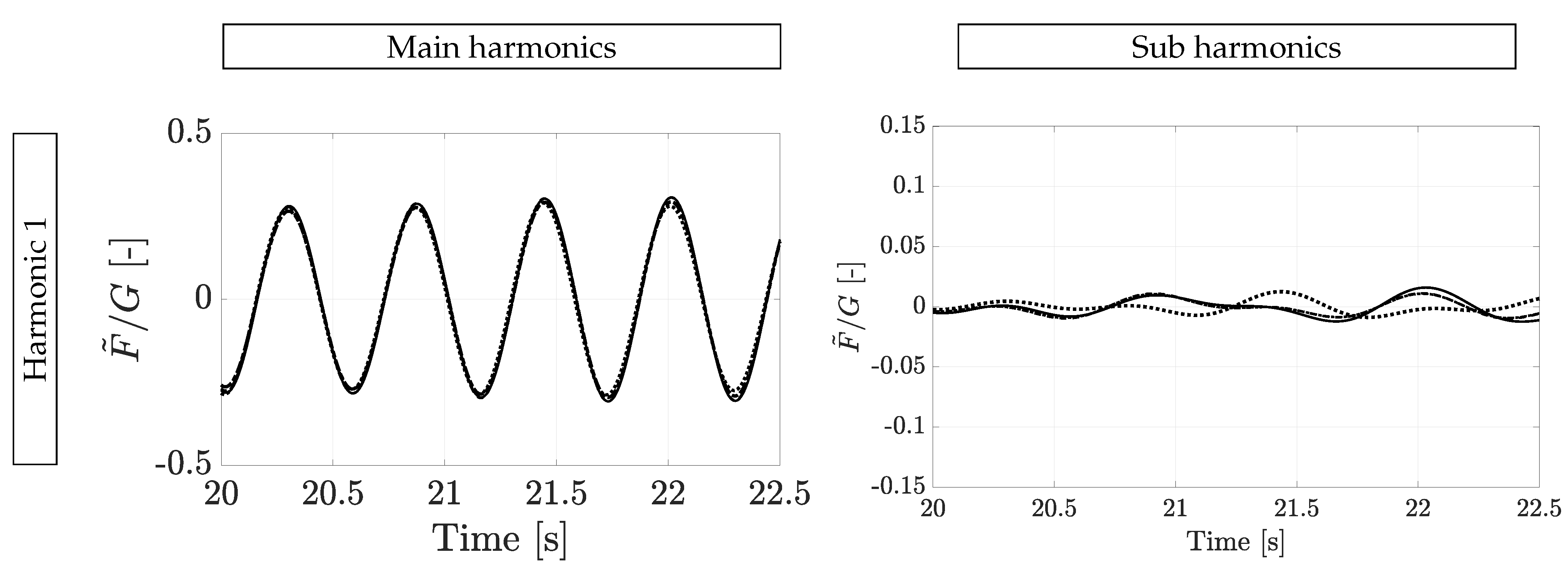
To allow a correct comparison of the three different RMs, the pre-defined DLFs in RM II and RM III are not the ones defined by Živanović’s load model but instead the average values as observed during the experimental setup (Section 3.1). Given the relatively small number of trials (43), it would be possible that there is a difference in the mean of the experimental DLFs and the DLFs described by Živanović’s load model. Hence, a systematic error would be introduced and bias the comparison of the results. An example of the reconstructed versus the measured contact force for the reference trial is shown in Figure 11 and Figure 12.
The reconstructed contact forces are compared to the measured ones, and the quality is assessed in terms of the NRMSE (Equation (17)), which is calculated as:
NRMSE = 1 T 0 T | F ( t ) F ˜ X ( t ) | 2 d t max ( F ( t ) ) min ( F ( t ) ) × 100 %
with F ( t ) the measured (true) contact force and F ˜ X ( t ) the reconstructed contact force using RM X with X { I ,   II ,   III } one of the three presented RMs.
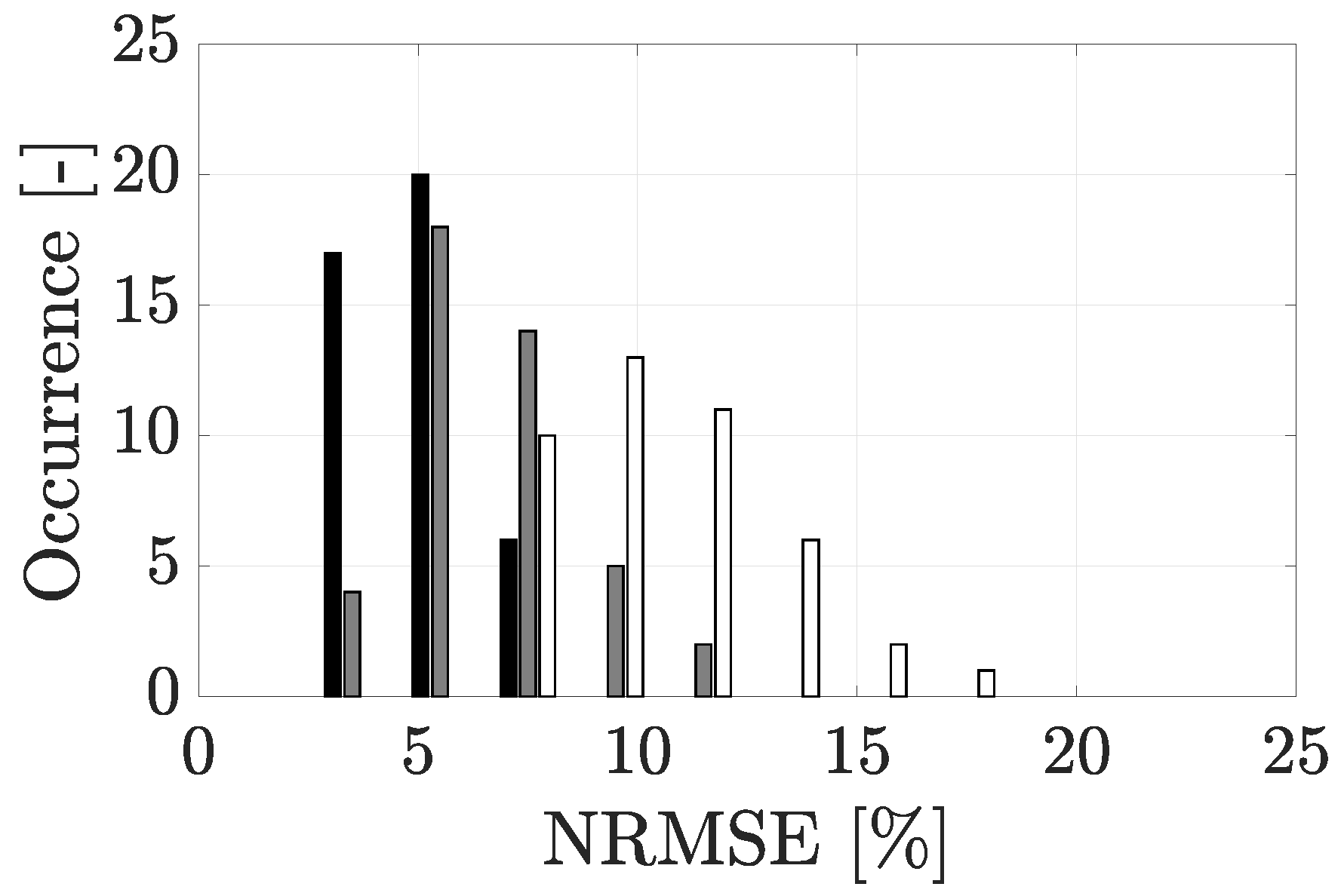
The NRMSE is calculated for all trials and summarized in a histogram (Figure 13) and in Table 3. The reconstructed vertical contact force is evaluated both for the entire frequency content as well as per main/sub harmonic. Human-induced loading is narrow banded consisting of multiple harmonics. While the first main harmonic component is the largest one, the higher ones can still induce high vibration levels in case resonance is attained with these higher harmonics. Given the fact that civil engineering structures are generally lightly damped and lively due to a small modal mass associated with slender designs, even the higher harmonics can provoke high vibration levels. In the literature, the quality of reconstruction is generally assessed for the entire frequency content. The result is, consequently, that the first main harmonic component dominates the assessment quantity as its power content is much higher than the other harmonics. Therefore, the quality of reconstruction of the higher harmonics is underrepresented. A harmonic-component-wise assessment of the reconstructed force was first introduced by Živanović et al. for reconstructed jumping loading [31].
The difference between the reference and cross-reference group is relatively small and neglected in the further discussion. Furthermore, it is observed that the new methodologies (RM I and RM II) provide more accurate results when considering the entire frequency content between 0 Hz and 10 Hz with an NRMSE of respectively 5%, 7%, and 11% for RM I, II, and III. This observation can directly be attributed to the fact that there is a decreasing degree of registered L5 acceleration that is accounted for for RM I to RM III. Similar observations are made for the main and sub harmonic components.
Shahabpoor et al. [12] used a test-group-specific (6 participants) template function to reconstruct the contact forces (Section 1) and found an average NRMSE of 6%, meaning that the proposed force RMs, in particular RM I and RM II, are competitive with this state-of-the-art force reconstruction method technique. The advantage is that RM I and RM II allow for a cheap implementation procedure and, assuming that the averaged transfer function is based on a sufficiently large training dataset, no test-group-specific training is required for these RMs.
RM I provides the most accurate reconstruction compared to RM II and RM III for the first and second main harmonic component (average NRMSE of 3%/6%/9% for main harmonic 1, average NRMSE of 10%/14%/25% for main harmonic 2). For the third main harmonic, RM I and RM II return a similar accuracy which is more accurate than RM III (average NRMSE of 12%/12%/22%). For the fourth main harmonic, RM II and RM III provide better results than RM I (average NRMSE of 19%/16%/16%). In case of the fifth main harmonic, RM I and RM II preform nearly equally and somewhat better than RM III (average NRMSE of 16%/14%/21%). In case of the sub harmonic components, it is observed that RM I and RM II provide a comparable accuracy. The average NMRSE is nearly half of the NMRSE obtained by using RM III (Table 3). It is concluded that overall RM I returns the most accurate reconstruction. This is in line with the expectation as method employs the most in-situ registered information for the contact force reconstruction. Moreover, the sensor is placed at L5, and the sensor is firmly fixed to the human body by a strap resulting in a low influence of soft-tissue artifacts.

4. Contact Force Reconstruction on Vibrating Surfaces

The majority of contact force reconstruction techniques and related contact force models in the literature are established in rigid-surface conditions. This is also the case with the reconstruction methods presented in the previous paragraph. The methods consider the internally-driven L5 acceleration u ¨ L 5 RS ( t ) and its relation with the internally-driven contact force F RS ( t ) , and is written as:
F ˜ RS ( t ) = F X u ¨ L 5 RS ( t )
where F X denotes the contact force reconstruction operator using RM X { I , II , III } and contains all the necessary operations to reconstruct the internally-driven contact force F ˜ RS ( t ) from the internally-driven L5 acceleration u ¨ L 5 RS ( t ) (presented in Section 3.4).
In case of walking on a vibrating surface, an additional component is present in the L5 acceleration and contact force due to HSI. As such, the total L5 acceleration reads u ¨ L 5 tot ( t ) = u ¨ L 5 RS ( t ) + u ¨ L 5 int ( t ) , while the total contact force reads F tot ( t ) = F RS ( t ) + F int ( t ) (Equation (3)). The goal is to investigate what is obtained in case the force reconstruction operator is applied on the total L5 accelerations. In other words, it is examined how the reconstructed contact force F ˜ ( t ) = F X u ¨ L 5 tot ( t ) should be interpreted.
A numerical-experimental study is conducted to assess this research question. A procedure to numerically estimate the additional L5 accelerations due to mechanical HSI is presented in Section 4.1. Then, Section 4.2 presents the different strategies for the contact force reconstruction in vibrating-surface conditions. Section 4.3 presents the framework of the numerical-experimental study while Section 4.4 presents the results of the different approaches.

4.1. Numerical Estimation of the Additional L5 Accelerations Resulting from Human–Structure Interaction

Previously, the L5 accelerations were related to the contact forces in rigid-surface conditions (Section 3.3). The relation was modeled using a transfer function: F RS ( t ) G G = h ( t ) u ¨ L 5 RS ( t ) g (see also Equation (12)). Assuming that the governing human body dynamics hold for the mechanical HSI effects as well, one can estimate the additional interaction acceleration at L5 u ¨ L 5 int ( t ) by applying a deconvolution on F H 1 int ( t ) :
u ¨ L 5 int ( t ) g = h 1 ( t ) F H 1 int ( t ) G
where it is noted that F H 1 int ( t ) does not contain the static gravity component G and therefore G is not subtracted from F H 1 int ( t ) . It is noteworthy that, from a numerical point of view, deconvolution can be numerically unstable as the transfer function can possess poles in the frequency domain. As such, a division by nearly zero is obtained leading to inaccurate results. In the present case, however, the established transfer function does not possess any poles as it is established exploiting the narrow-banded nature of the L5 acceleration and contact force (see also Equations (13) and (14)). Therefore, the deconvolution boils down to a rescaling operation followed by a time shift. In contrast to the internally-driven components, the interaction component is not narrow banded, per se. Therefore, the deconvolution is done using a single value for the rescaling and time shifting, which is obtained as the frequency-averaged value of the transfer function.
In case one experimentally registers the L5 and/or contact force of a pedestrian in vibrating-surface conditions, the total quantity is registered. It is impossible to divide this registered total quantity into the internally-driven and interaction components. Therefore, in the present work, the interaction L5 accelerations are estimated numerically. To this end, the internally-driven interaction forces as registered in laboratory conditions (Section 3.1) are applied on a coupled crowd-structure system. The equations of motion (Equation (5)) are solved for the modal accelerations and the interaction acceleration of each human body model u ¨ H 1 int ( t ) representing the mechanical HSI effect of each occupying pedestrian. The latter is used to obtain the interaction contact force component of the driven mass as F H 1 int ( t ) = m H 1 u ¨ H 1 int ( t ) (Equation (3)). Finally, the interaction L5 acceleration is estimated using Equation (19).

4.2. Contact Force Reconstruction Strategies

The contact force is reconstructed using the L5 accelerations. In rigid-surface conditions, the internally-driven L5 acceleration u ¨ L 5 RS ( t ) is measured and is used to reconstruct the internally-driven contact force F ˜ RS ( t ) . In vibrating-surface conditions, the total L5 acceleration u ¨ L 5 tot ( t ) is measured and is used to reconstruct the total contact force F ˜ tot ( t ) . The formal framework of all reconstruction strategies is presented in the sub paragraphs below.

4.2.1. Internally-Driven Contact Force Reconstruction Using the Internally-Driven L5 Accelerations

For the reconstruction of the ground reaction forces using the L5 accelerations in rigid-surface conditions (RCS), three reconstruction methods are presented (Section 3.4):
F ˜ X RS , RSC ( t ) = F X u ¨ L 5 RS ( t )
where the operator F X comprises all the necessary actions of reconstruction method X { I ,   II ,   III } applied on the internally-driven L5 accelerations u ¨ L 5 RS ( t ) yielding the reconstructed internally-driven contact forces F ˜ X RS , RCS ( t ) .

4.2.2. Total Contact Force Reconstruction Using the Total L5 Accelerations

In vibrating-surface conditions, the total L5 accelerations are registered. The quantity consists of the true internally-driven L5 acceleration, the interaction L5 acceleration and the measurement error. If it is assumed that the human body dynamics that relate the internally-driven and interaction contact force and L5 acceleration are identical, one could opt to reconstruct the total contact force by applying the established transfer function (Section 3.3) on the total L5 acceleration. The transfer function employs all the information of the registered L5 acceleration. Obviously, only RM I can be applied in this case since RM II and RM III use predefined DLFs. The reconstructed total contact force reads:
F ˜ I tot ( t ) = m H 0 u ¨ s ( t ) + F I ( u ¨ L 5 tot ( t ) )
where m H 0 u ¨ s ( t ) is the estimated contribution of the non-driven body mass and F I ( u ¨ L 5 tot ( t ) ) the estimated contribution of the driven mass.

4.2.3. Internally-Driven Contact Force Reconstruction Using the Total L5 Accelerations

It is shown later that the interaction L5 accelerations are small compared to the total ones. Therefore, one can also opt to consider the total L5 acceleration as an approximation of the internally-driven ones, thereby assuming that u ¨ L 5 tot ( t ) u ¨ L 5 RS ( t ) or u ¨ L 5 int ( t ) u ¨ L 5 RS ( t ) . This paragraph considers the case where the total L5 accelerations are considered as an estimation of the internally-driven ones. As such, the internally-driven contact forces in vibrating-surface conditions (VSC) are reconstructed as:
F ˜ X RS , VSC ( t ) = F X ( u ¨ L 5 tot ( t ) )

4.3. Framework of the Numerical-Experimental Example

The contact force reconstruction procedure on vibrating surfaces is illustrated by a numerical example. The quantities of the example are chosen such that a representative scenario of the Eeklo Footbridge Benchmark Dataset as presented in [8] is obtained.
The modal parameters of the digital twin of the structure presented in the corresponding Eeklo Footbridge Benchmark Dataset are considered and stored in Φ , Ω 2 , Γ [8]. The structure consists of 14 modes below 12 Hz and are calculated with a detailed FE model, which is calibrated using experimental operational modal analysis data [17]. The first six mode shapes are shown in Figure 14. A flow S p ( t ) consisting of 148 persons (≈0.50 pers./m2) is considered where the trajectories of the participants correspond to those as registered in the Eeklo Footbridge Benchmark Dataset (total duration of 20 min) and shown in Figure 15. The HSI is modeled by a moving spring–mass–damper (SMD) at each location of the pedestrian occupying the bridge (see also Figure 1b). The values are adopted from [19]: f H 1 = 3.25 Hz , ξ H 1 = 0.30 and μ H 1 = 0.95 .
The crowd-induced loading and related response of the numerical study are established by the following steps:
1.
The internally-driven contact forces F RS ( t ) are selected from the registered trials during the laboratory measurements on rigid surfaces (Section 3.1). As the total test duration is longer than the typical trial duration, the contact force and lower-back acceleration vector are repeated. As trials are selected multiple times, a random uniformly-distributed time shift is assigned and sampled from ± the average step period to avoid an artificial correlation between the pedestrians in the crowd. The reason to use the treadmill-identified contact forces and L5 accelerations in the present example instead of the L5 accelerations as collected in the Eeklo Footbridge Benchmark Dataset is twofold. First, only the L5 accelerations are registered in the Eeklo Footbridge Benchmark Dataset, and not the corresponding contact forces. Second, the total L5 accelerations are registered in-situ. It is not possible to extract the internally-driven and mechanical interaction components from the total L5 accelerations. Instead, an estimation of the mechanical interaction component is made by assuming the human body dynamics representing the mechanical HSI can be modeled by an SMD.
2.
The corresponding part of the L5 acceleration as registered during the laboratory experiments is selected and stored in the matrix U ¨ H 1 RS ( t ) . This quantity is used to determine the total human body accelerations (step 5) and the contact force reconstruction.
3.
The reference response is calculated by plugging in the internally-driven contact forces F RS ( t ) in Equation (5). The equation is solved for the modal accelerations Z ¨ ( t ) and the interaction human body accelerations U ¨ H 1 int ( t ) .
4.
The modal accelerations Z ¨ ( t ) are used to calculate the vertical acceleration at the middle of the central span u ¨ MCS ( t ) and the middle of the side span u ¨ MSS ( t ) . This structural acceleration quantity is hereafter referred to as the reference response.
5.
The kinetics of the SMD representing HSI are converted to interaction contact forces and the additional L5 accelerations (Equations (3) and (19)). An example of both quantities is shown in Figure 16. The interaction L5 accelerations are assumed to correspond to the additional kinetics that a pedestrian registers in case of walking on a vibrating surface as a result of the HSI. The total acceleration registered at the lower back is: U ¨ L 5 tot ( t ) = U ¨ L 5 RS ( t ) + U ¨ L 5 int ( t ) . This quantity is used for the contact force reconstruction.
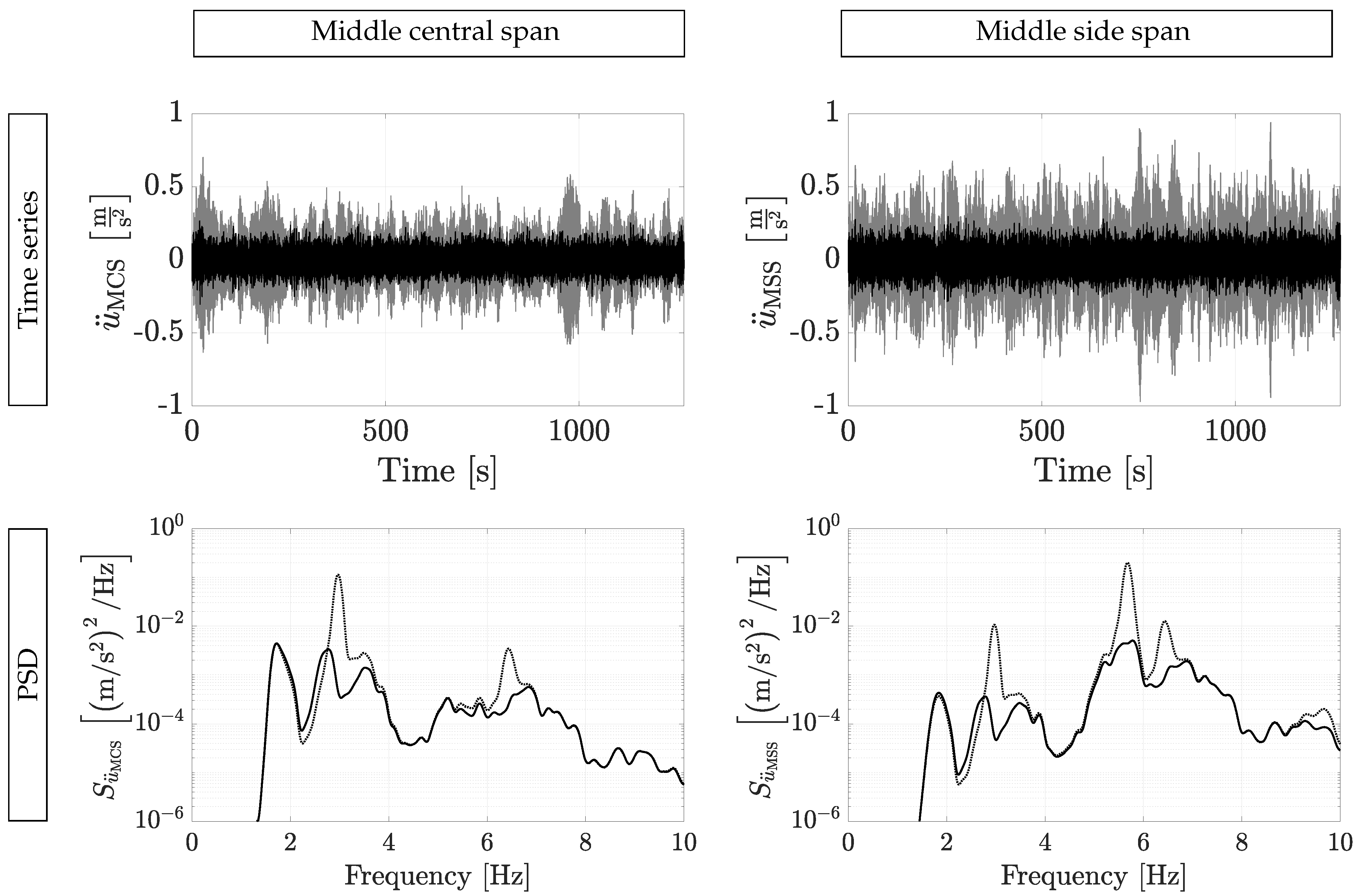
Figure 17 shows an example of the reference structural response at the middle of the central and side span, both with and without consideration of mechanical HSI. It is observed that the influence of mechanical HSI on the structural response is high, especially near the frequency regions of the eigenfrequencies of modes 2 ( f 2 = 2.97 Hz) and mode 5 ( f 5 = 5.68 Hz).
The difference in PSD of the structural response with and without the incorporation of HSI is quantified in terms of the relative difference in PSD. The considered frequency range is 0.5 Hz to 10 Hz. The relative difference in PSD of a time series u ¨ B ( t ) relative to a the PSD of a time series u ¨ A ( t ) is defined as:
Δ S u ¨ = f = 0.5 Hz f = 10 Hz | S u ¨ A ( f ) S u ¨ B ( f ) | d f f = 0.5 Hz f = 10 Hz S u ¨ A ( f ) d f
The relative difference of the reference response without incorporation of HSI to the reference response with HSI is, respectively, 5.15 and 7.63 for the middle of the central and side span. This value is a measure for the sensitivity of the reference response to HSI. This high difference indicates that HSI has a prominent influence on the structural response. This was one of the main motivations to choose for the Eeklo footbridge when establishing the Eeklo Footbridge Benchmark Dataset [8].
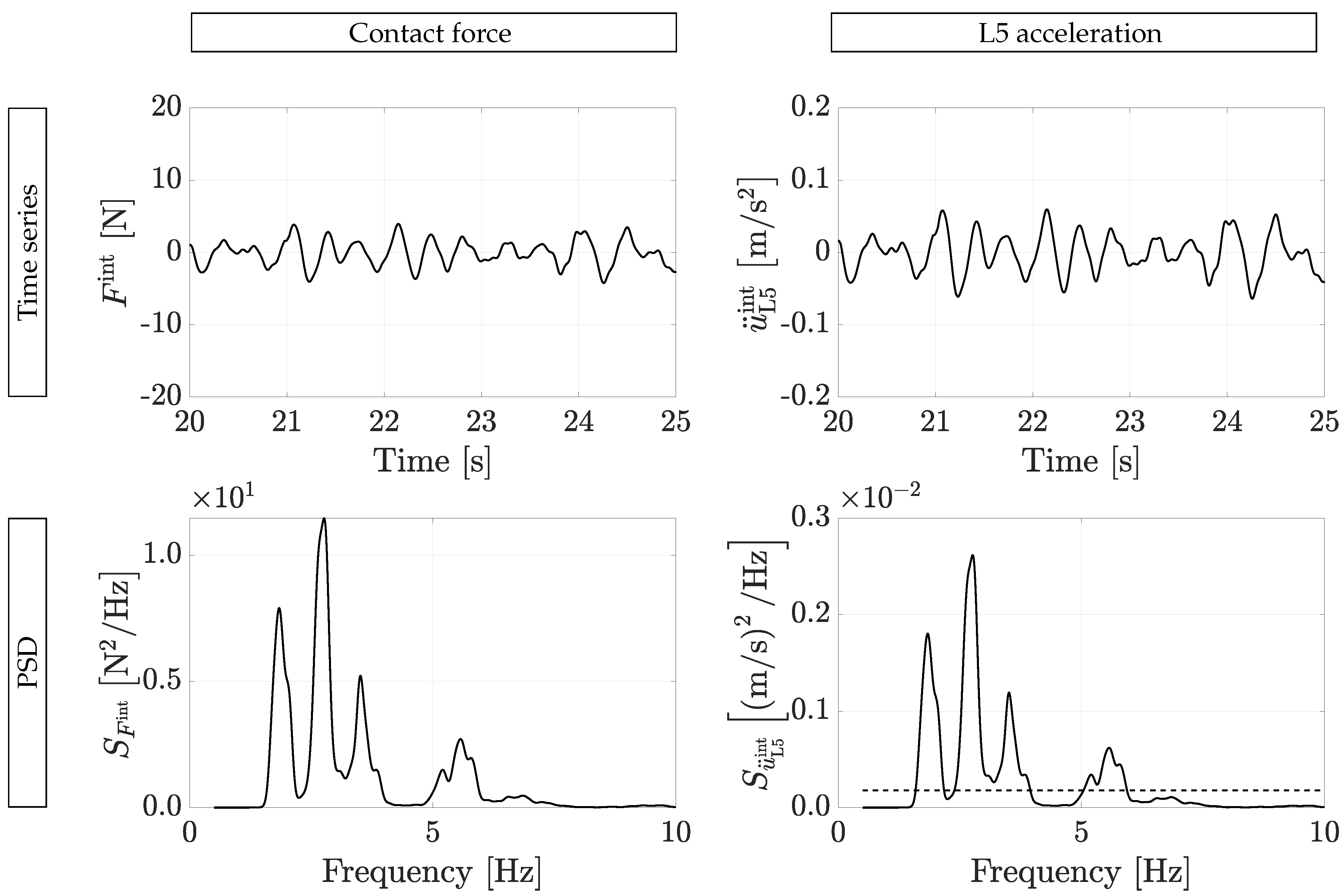
An example of the interaction contact force and interaction L5 acceleration (Figure 16) illustrates that the interaction components are very small compared to their internally-driven counterparts (Figure 2). On the contrary, the influence of these interaction components on the structural response is high (Figure 17).This can be attributed to the fact that a part of the frequency content of the interaction contact forces is near-resonant with mode 2 ( f 2 = 2.97 Hz) and mode 5 ( f 5 = 5.68 Hz), which are characterized by a low modal mass and modal damping ratio. Compared to the measurement noise of the low-cost sensors in the frequency band 0.5 Hz–10 Hz, a signal-to-noise ratio of the mechanical interaction L5 accelerations of 1.58 ≈ 1.99 dB is found, which is very low. This low value suggests that a direct total contact force reconstruction is not feasible.

4.4. Results of the Different Reconstruction Scenarios in Vibrating-Surface Conditions

First, the case is considered where the contact forces are reconstructed using the internally-driven L5 accelerations (elaborated in Section 4.2.1). The reconstructed internally-driven contact forces are applied on the equations of motion of the coupled crowd-structure system (Equation (5)). The relative differences in reconstructed and reference structural response for RM I/RM II/RM III, respectively, are 0.17/0.20/0.33 and 0.34/0.19/0.30 for the middle of the central and side span (white bars in Figure 18). The reconstruction error is nearly identical for all reconstruction methods, and is low compared to the sensitivity of the response to mechanical HSI.
Second, the case is considered where total contact forces are directly reconstructed using the total L5 accelerations (presented in Section 4.2.2). Only RM I is considered in the present case. The reconstructed total contact forces are applied on the equations of motion of the empty structure (Equation (4)) and solved for the structural response. Large reconstruction errors are found, with relative differences in PSD respectively of 2.35 and 6.03 for the middle of the central and side span (black bars in Figure 18). These errors are very high compared to the sensitivity of the response of mechanical HSI. This observation confirms the inadequacy for a direct total force reconstruction in the case of the Eeklo footbridge.
Third, the internally driven contact forces are reconstructed using the total L5 accelerations (presented in Section 4.2.3). The reconstructed internally-driven contact forces are applied on the equations of motion of the coupled crowd-structure system (Equation (5)). The relative differences in reconstructed and reference structural response for RM I/RM II/RM III, respectively, are 0.60/0.90/0.26 and 0.30/0.30/0.30 for the middle of the central and side span (gray bars in Figure 18). Compared to the case where the internally-driven contact force is reconstructed using the internally-driven L5 accelerations, a small increase in reconstruction error is found. The reconstruction error is low compared to the sensitivity of the response to mechanical HSI. RM III is the least affected by the additional interaction L5 accelerations, which is a logical consequence of the fact that this reconstruction method merely employs the first main normalized harmonic of the L5 acceleration. In addition, RM III returns the most accurate result in terms of relative PSD between the reconstructed and the reference structural acceleration, for both locations. It is to be noted, however, that, in this particular case, the actual participant-averaged DLFs were available.
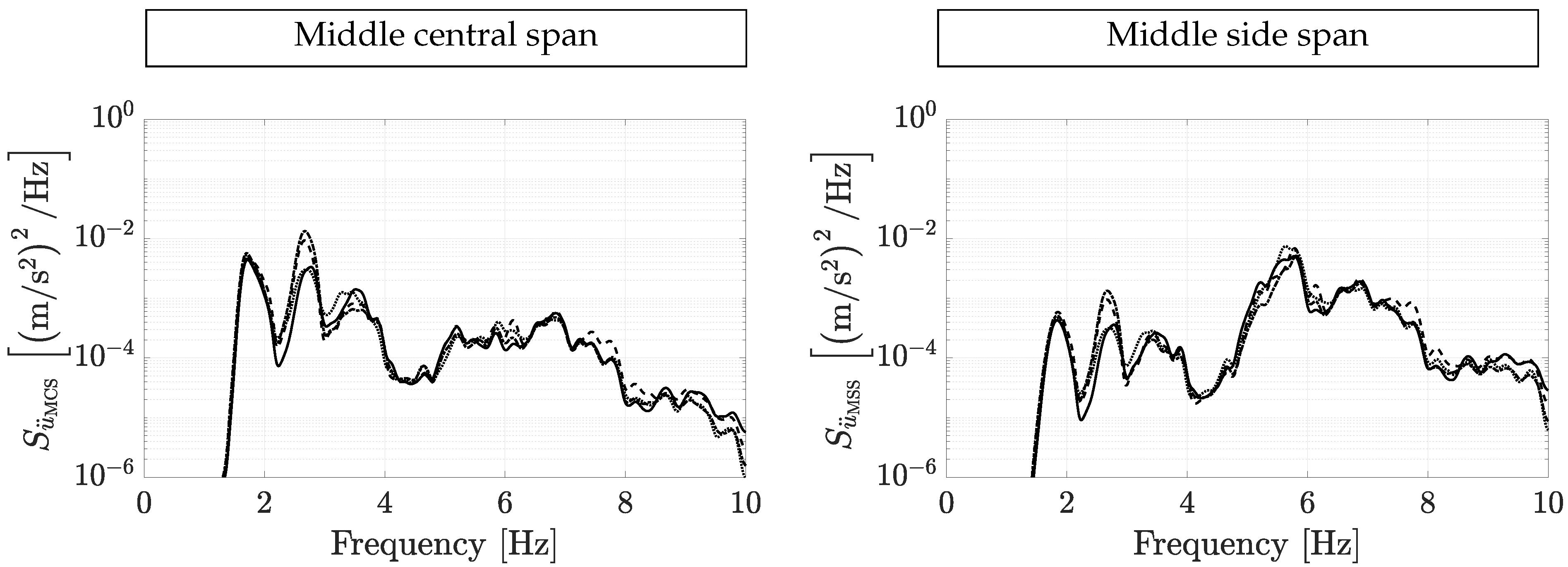
The comparison in PSD between the true and reconstructed response for all reconstruction methods is shown in Figure 19. All reconstruction methods yield a good reconstruction. However, it is found that, for RM I and RM II, an overestimation of the response is present around 3 Hz where no overestimation is found in case of RM III. This overestimation can be ascribed to the present additional mechanical HSI L5 accelerations, which does affect the reconstructed contact force employing RM III.
Overall, it is concluded that all three reconstruction methods are capable for reconstructing the structural response using the total L5 accelerations in case of the Eeklo footbridge. To this end, the total L5 accelerations are considered as a good approximation for the internally-driven ones. On the other hand, a direct total contact force reconstruction is inadequate for the Eeklo footbridge.

5. Conclusions

The paper investigates how the contact force can be reconstructed using the measured lower-back accelerations registered by low-cost sensors on both rigid and vibrating surfaces. The relation between the contact force and L5 acceleration is modeled using a transfer function. To this end, an experimental data set is established comprising both the contact forces and corresponding lower-back accelerations, registered with the low-cost sensors. The narrow-banded nature of both signals is exploited by simplifying the transfer function to a power scaling and time shift per main and sub harmonic component. It is found that the transfer function values vary over the harmonic components, thus confirming the added value of using a transfer function rather than a single scaling constant.
To reconstruct the contact forces, two new reconstruction methods are presented. RM I employs the averaged transfer function values. RM II uses the phase information of the averaged transfer function while the power of the reconstructed contact force is determined using predefined values. These values can be adopted from literature models or determined for a specific group through measurements. RM III is a method previously established in the literature and determines the consecutive step-by-step frequencies combined with a single-step literature model. The reconstruction quality is assessed by means of the NMRSE. For the frequency content between 0.5 Hz and 10 Hz containing the frequency content of the first five main and sub harmonic components, the NMRSE of RM I, RM II, and RM III, respectively, is 5%, 7%, and 11%. RM I and RM II provide a comparable accuracy considering the frequency content between 0.5 Hz and 10 Hz as conventional reconstruction methodologies using expensive measurement techniques. For the main harmonic components, the NRMSE respectively is 3%, 6%, and 9% for harmonic 1 and 10%, 14%, and 25% for harmonic 2. The reconstruction quality decreases from RM I to RM II to RM III, which is ascribed to the decreasing degree of the registered information that is accounted for in the reconstruction methods.
The performance of the reconstruction methods in case of walking on a vibrating surface is assessed by means of a numerical study. The framework of the study adopts the quantities as presented in the Eeklo Footbridge Benchmark Dataset, except for the contact forces. The considered contact forces are adopted from the laboratory experiment. The comparison is made between the structural response that is calculated using either the measured or reconstructed contact forces. The latter considers the total lower-back accelerations, which are the combination of the measured internally-driven component and numerically estimated additional interaction component. The results show that directly reconstructing the total contact forces yields inaccurate results. Instead, it is beneficial to consider the total body accelerations as a good approximation of the internally-driven ones. As such, one can reconstruct the internally-driven contact forces using the total lower-back accelerations and modeling the interaction effect separately. Furthermore, it is observed that the three reconstruction methods perform nearly equally on a vibrating surface, as opposed to a rigid surface. The obtained conclusions hold for the considered structure, the Eeklo footbridge in this case. However, the presented methodology can be applied on virtually any structure.

Author Contributions

Conceptualization, methodology, investigation, visualization, writing—original draft preparation: J.V.H.; Experimental work: J.V.H., B.V., K.V.N., P.V.d.B.; writing—review and editing, B.V., K.V.N., P.V.d.B.; supervision, K.V.N., P.V.d.B. All authors have read and agreed to the published version of the manuscript.

Funding

The first author is a doctoral fellow of the Research Foundation Flanders (FWO, 1S42317N). The second author is a postdoctoral fellow of the Research Foundation Flanders (FWO, 12E0816N). The financial support is gratefully acknowledged.

Institutional Review Board Statement

Not applicable.

Informed Consent Statement

Not applicable.

Data Availability Statement

Not applicable.

Conflicts of Interest

The authors declare no conflict of interest.

Abbreviations

The following abbreviations are used in this manuscript:
DAFDynamic acceleration factor
DLFDynamic loading factor
HSIHuman–structure interaction
L55th Lumbar vertebra
PSDPower spectral density
RMReconstruction method
SMDSpring mass damper

References

  1. Van Nimmen, K.; Lombaert, G.; De Roeck, G.; Van den Broeck, P. Vibration serviceability of footbridges: Evaluation of the current codes of practice. Eng. Struct. 2014, 59, 448–461. [Google Scholar] [CrossRef]
  2. Van Nimmen, K.; Lombaert, G.; De Roeck, G.; Van den Broeck, P. The impact of vertical human–structure interaction on the response of footbridges to pedestrian excitation. J. Sound Vib. 2017, 402, 104–121. [Google Scholar] [CrossRef] [Green Version]
  3. Živanović, S.; Pavic, A.; Reynolds, P. Human-structure dynamic interaction in footbridges. Proc. Inst. Civ. Eng. Bridge Eng. 2005, 158, 165–177. [Google Scholar] [CrossRef]
  4. Živanović, S.; Pavic, A.; Reynolds, P. Vibration serviceability of footbridges under human-induced excitation: A literature review. J. Sound Vib. 2005, 279, 1–74. [Google Scholar] [CrossRef] [Green Version]
  5. Association Française de Génie Civil, Sétra/AFGC. Sétra: Evaluation du Comportement Vibratoire des Passerelles Piétonnes Sous L’action des Piétons (Assessment of Vibrational Behaviour of Footbridges Under Pedestrian Loading); AFGC: Paris, France, 2006. [Google Scholar]
  6. Heinemeyer, C.; Butz, C.; Keil, A.; Schlaich, M.; Goldack, A.; Lukić, M.; Chabrolin, B.; Lemaire, A.; Martin, P.; Cunha, A.; et al. Design of Lightweight Footbridges for Human Induced Vibrations; EUR 23984 EN; European Commission: Luxembourg, 2009. [Google Scholar]
  7. Živanović, S. Benchmark footbridge for vibration serviceability assessment under vertical component of pedestrian load. J. Struct. Eng. 2012, 138, 1193–1202. [Google Scholar] [CrossRef] [Green Version]
  8. Van Nimmen, K.; Van Hauwermeiren, J.; Van den Broeck, P. The Eeklo footbridge: Benchmark dataset on pedestrian-induced vibrations. J. Bridge Eng. 2021. forthcoming. [Google Scholar] [CrossRef]
  9. Bocian, M.; Brownjohn, J.M.; Racic, V.; Hester, D.; Quattrone, A.; Gilbert, L.; Beasley, R. Time-dependent spectral analysis of interactions within groups of walking pedestrians and vertical structural motion using wavelets. Mech. Syst. Signal Process. 2018, 105, 502–523. [Google Scholar] [CrossRef]
  10. Bocian, M.; Brownjohn, J.M.; Racic, V.; Hester, D.; Quattrone, A.; Monnickendam, R. A framework for experimental determination of localised vertical pedestrian forces on full-scale structures using wireless attitude and heading reference systems. J. Sound Vib. 2016, 376, 217–243. [Google Scholar] [CrossRef] [Green Version]
  11. Toso, M.A.; Gomes, H.M.; Da Silva, F.T.; Pimentel, R.L. Experimentally fitted biodynamic models for pedestrian-structure interaction in walking situations. Mech. Syst. Signal Process. 2016, 72–73, 590–606. [Google Scholar] [CrossRef]
  12. Shahabpoor, E.; Pavic, A. Estimation of vertical walking ground reaction force in real-life environments using single IMU sensor. J. Biomech. 2018, 79, 181–190. [Google Scholar] [CrossRef] [PubMed]
  13. Van Nimmen, K.; Zhao, G.; Seyfarth, A.; Van den Broeck, P. A Robust Methodology for the Reconstruction of the Vertical Pedestrian-Induced Load from the Registered Body Motion. Vibration 2018, 1, 18. [Google Scholar] [CrossRef] [Green Version]
  14. Guo, Y.; Storm, F.; Zhao, Y.; Billings, S.A.; Pavic, A.; Mazzà, C.; Guo, L.Z. A new proxy measurement algorithm with application to the estimation of vertical ground reaction forces using wearable sensors. Sensors 2017, 17, 2181. [Google Scholar] [CrossRef] [PubMed]
  15. Denoth, J. Chapter: Load on the locomotor system and modelling. In Biomechanics of Running Shoes; Nigg, B., Ed.; Human Kinetics Publishers: Champaign, IL, USA, 1986; pp. 63–116. [Google Scholar]
  16. Racic, V.; Brownjohn, J.M.W.; Pavic, A. Reproduction and application of human bouncing and jumping forces from visual marker data. J. Sound Vib. 2010, 329, 3397–3416. [Google Scholar] [CrossRef]
  17. Van Nimmen, K.; Lombaert, G.; Jonkers, I.; De Roeck, G.; Van den Broeck, P. Characterisation of walking loads by 3D inertial motion tracking. J. Sound Vib. 2014, 333, 5212–5226. [Google Scholar] [CrossRef] [Green Version]
  18. Ahmadi, E.; Caprani, C.; Živanović, S.; Evans, N.; Heidarpour, A. A framework for quantification of human–structure interaction in vertical direction. J. Sound Vib. 2018, 432, 351–372. [Google Scholar] [CrossRef] [Green Version]
  19. Matsumoto, Y.; Griffin, M.J. Mathematical models for the apparent masses of standing subjects exposed to vertical whole-body vibration. J. Sound Vib. 2003, 260, 431–451. [Google Scholar] [CrossRef]
  20. Vasilatoua, V.; Harrisona, R.; Nikitasb, N. Development of a human–structure dynamic interaction model for human sway for use in permanent grandstand design. In Proceedings of the 10th International Conference on Structural Dynamics, EURODYN 2017, Rome, Italy, 10–13 September 2017; Vestroni, F., Romeo, F., Gattulli, V., Eds.; Elsevier: Amsterdam, The Netherlands, 2017; pp. 1877–7058. [Google Scholar] [CrossRef]
  21. Winter, D.A. The Biomechanics and Motor Control of Human Gait; University of Waterloo Press: Waterloo, ON, Canada, 1988; Volume 74, p. 94. [Google Scholar] [CrossRef]
  22. Brownjohn, J.M.W. Energy dissipation from vibration floor slabs due to human–structure interaction. J. Shock Vib. 2001, 8, 315–323. [Google Scholar] [CrossRef]
  23. Zheng, X.; Brownjohn, J.M.W. Modelling and simulation of human-floor system under vertical vibration. In Smart Structures and Materials 2001: Smart Structures and Integrated Systems; Davis, L., Ed.; International Society for Optics and Photonics: Bellingham, WA, USA, 2001; Volume 4327, pp. 513–520. [Google Scholar]
  24. Duysens, J.; Jonkers, I.; Verschueren, S. MALL: Movement & posture Analysis Laboratory Leuven; Interdepartmental Research Laboratory at the Faculty of Kinisiology and Rehabilitation Sciences-KU Leuven: Leuven, Belgium, 2019. [Google Scholar]
  25. Vicon Motion Systems. Vicon Motion Systems Product Manuals; Vicon Motion Systems: Los Angeles, CA, USA, 2019. [Google Scholar]
  26. Živanović, S.; Pavić, A.; Reynolds, P. Probability-based prediction of multi-mode vibration response to walking excitation. Eng. Struct. 2007, 29, 942–954. [Google Scholar] [CrossRef]
  27. MATLAB. R2016b; The MathWorks Inc.: Natick, MA, USA, 2016. [Google Scholar]
  28. Gulf Coast Data Concepts. X16-1D: User manual rev B; GCDC LLC: Waveland, MS, USA, 2016. [Google Scholar]
  29. Xsens Technologies B.V. In MTw User Manual; Xsens: Enschede, The Netherlands, 2010.
  30. Butz, C. Beutrag zur Berechnung fussgängerinduzierter Brückenschwingungen—Shaker Verlag (Contribution to the Determination of Pedestrian Induced Bridge Vibrations). Ph.D. Thesis, RWTH Aachen, Aachen, Germany, 2006. [Google Scholar]
  31. McDonald, M.G.; Živanović, S. Measuring Ground Reaction Force and Quantifying Variability in Jumping and Bobbing Actions. J. Struct. Eng. 2017, 143, 1–14. [Google Scholar] [CrossRef]
  32. Van Hauwermeiren, J.; Van Nimmen, K.; Van den Broeck, P.; Vergauwen, M. Vision-Based Methodology for Characterizing the Flow of a High-Density Crowd on Footbridges: Strategy and Application. Infrastructures 2020, 5, 51. [Google Scholar] [CrossRef]
Figure 1. Schematic representation of the human body dynamics modeled by a non-driven ( m H 0 ) and a driven mass ( m H 1 ). Connection with the supporting surface modeled (a) generically and (b) by a spring and viscous damper.
Vibration 04 00015 g001
Figure 2. Vertical contact force with the static component removed from the reference trial (average walking speed of 4.5 km/h, average step frequency of 1.75 Hz) (a) time series and (b) amplitude spectrum normalized to the body weight.
Vibration 04 00015 g002
Figure 3. Vertical L5 acceleration with the static component removed of the reference trial: (a) time series and (b) amplitude spectrum normalized to the gravity constant.
Vibration 04 00015 g003
Figure 4. (a) PSD of the vertical contact force of the reference trial (solid line) with indication of the maximum value (×) of which the abscissa corresponds to the estimated average step frequency f s , av and (b) histogram of all the trials (bars) with indication of the group-averaged value (dashed line).
Vibration 04 00015 g004
Figure 5. Statistical characterization of the measurement noise in terms of the variance: (a) histogram and (b) empirical cumulative distribution (solid line) with indication of the 95% percentile value (dashed line).
Vibration 04 00015 g005
Figure 6. Estimated transfer function for the reference trial: (a) magnitude and (b) phase angle.
Vibration 04 00015 g006
Figure 7. Histogram of the components of the estimated transfer function based for main harmonic 1 (black), 2 (dark gray) and 3 (light gray): (a) magnitude and (b) phase angle.
Vibration 04 00015 g007
Figure 8. The averaged stochastic transfer function: mean (solid line) and 95% confidence bounds (dashed lines) of the (a) magnitude and (b) phase value. The frequency is normalized to the average step frequency.
Vibration 04 00015 g008
Figure 9. The experimentally observed relationship between the dynamic acceleration factor (DAF) and dynamic loading factor (DLF). Indication of the magnitude of the transfer function (slope of the dashed line) which is used in RM I and the DLF proposed by the load model of Živanović et al. [26] and is used in RM II (red dotted line).
Vibration 04 00015 g009aVibration 04 00015 g009b
Figure 10. Illustration of the contact force reconstruction method provided in [13]: (a) L5 acceleration (black solid line) and fundamental main harmonic component (gray solid line) with indication of the consecutive footfalls corresponding to the local minima of the fundamental main harmonic (gray dashed lines), (b) step-by-step contact force reconstruction using Butz’s single-step force model for one foot (black) and the other foot (gray).
Vibration 04 00015 g010
Figure 11. Comparison of the measured (solid line) and reconstructed contact force using RM I (dashed line), RM II (dash-dotted line), or RM III (dotted line): (a) relevant zoom of the time series and (b) amplitude spectrum.
Vibration 04 00015 g011
Figure 12. Relevant zoom of the time series of the contact force of the reference trial for the different harmonic components: measured (solid line) and reconstructed contact force using RM I (dashed line), RM II (dash-dotted line), and RM III (dotted line).
Vibration 04 00015 g012aVibration 04 00015 g012b
Figure 13. Histogram of the NRMSE of the reconstructed to the measured contact force using RM I (black), RM II (gray) or RM III (white).
Vibration 04 00015 g013
Figure 14. Top and side view, eigenfrequency and damping ratio of the first five modes of the Eeklo footbridge, after [17].
Vibration 04 00015 g014
Figure 15. Heat map of the position for the case of walking for half a bridge deck (with length L and width B) during test 1 of pedestrian density 0.50 pers./m2: (a) a single pedestrian and (b) the entire crowd (after [32]).
Vibration 04 00015 g015
Figure 16. The interaction contact force and interaction L5 acceleration of a representative participant: time series and PSD (solid line) with an indication of the measurement noise or the low-cost sensors (dashed line).
Vibration 04 00015 g016
Figure 17. The vertical structural accelerations of the reference response with (black) and without mechanical HSI (gray) at the middle of the central span and the middle of the side span: time series and PSD.
Vibration 04 00015 g017
Figure 18. Relative error in PSD of the reconstructed to the reference structural response at the middle of the central span and middle of the side span. The internally-driven contact forces are reconstructed using either the internally-driven L5 accelerations (white) or the total L5 accelerations (gray) using three different reconstruction methods. The total contact forces are reconstructed using the total L5 accelerations (black, only reconstruction method I). The dashed horizontal line is the relative difference in PSD of the vertical structural acceleration with and without mechanical HSI.
Vibration 04 00015 g018
Figure 19. PSD of the vertical structural response at the middle of the central span and middle of the side span: reference response (solid), reconstructed response where the internally-driven contact forces are reconstructed using the total L5 accelerations using RM I (dashed), RM II (dash-dotted), or RM III (dotted).
Vibration 04 00015 g019
Table 1. Overview of the participants, mean, and standard deviation: gender, age, height, mass and considered treadmill speeds.
ParticipantGenderAge [years]Height [m]Mass [kg]Treadmill Speeds [km/h]
1male251.82774.00, 4.50, 5.00
2male221.77724.00, 4.50, 5.00
3male511.75774.00, 4.50, 5.00
4male271.89724.00, 4.50, 5.00
5male281.90854.00, 4.50, 5.00
6female321.66544.00, 4.50, 5.00
7male241.80614.00, 4.50, 5.00
8male241.87824.25, 4.75, 5.25
9male241.85794.50, 5.00, 5.50
10male241.73714.00, 5.00, 5.50
11male211.85784.25, 5.25, 5.75
12male221.85774.50, 5.00, 6.00
13male221.65744.00, 4.50, 5.00
14female231.71704.25, 4.75, 5.25
15male211.77814.50, 5.25, 6.00
Mean 261.7974.04.70
Standard deviation 7.50.088.00.60
Table 2. Correlation coefficient (CC) between the DAF and DLF for the different harmonics.
Main HarmonicsSub Harmonics
1234512345
CC0.960.730.360.460.400.890.760.460.760.63
Table 3. Summary of the NRMSE [%] of the reconstructed contact force using the different reconstruction methods with respect to the measured contact force.
Frequency Content0 Hz–10 HzMain HarmonicsSub Harmonics
1234512345
RM I531012191647101316
RM II761412161448101213
RM III11925221621819192019
Publisher’s Note: MDPI stays neutral with regard to jurisdictional claims in published maps and institutional affiliations.