
Article

Numerical Investigation on Thermal-Mechanical Coupling Behavior and Fire Resistance Performance of Steel Structures in Substation Fires

1
State Grid Zhejiang Electric Power Research Institute, Hangzhou 310014, China
2
School of Naval Architecture, Ocean and Energy Power Engineering, Wuhan University of Technology, Wuhan 430070, China
3
State Key Laboratory of Silicate Materials for Architectures, Wuhan University of Technology, Wuhan 430070, China
*
Author to whom correspondence should be addressed.
Fire 2026, 9(5), 183; https://doi.org/10.3390/fire9050183
Submission received: 27 January 2026 / Revised: 9 April 2026 / Accepted: 19 April 2026 / Published: 27 April 2026
(This article belongs to the Special Issue Recent Developments in Flame Retardant Materials, 2nd Edition)

Abstract

Transformer fires within indoor substations constitute severe hydrocarbon fire scenarios characterized by rapid heat release rates and extreme peak temperatures, posing a critical threat to the structural integrity of steel frameworks and power grid stability. To rigorously assess structural safety under such conditions, this study employs a sequential thermal-mechanical coupled numerical methodology combining Computational Fluid Dynamics (CFD) and Finite Element Analysis (FEA). Focusing on a 110 kV indoor substation, the research simulates the transient, non-uniform temperature fields induced by transformer oil combustion and analyzes the thermo-mechanical response of key steel components. Furthermore, the protective efficacy of two non-intumescent coatings (Material A and Material B) with distinct thermal conductivities is systematically evaluated. Computational results elucidate significant thermal stratification, with upper-level structures sustaining exposure to temperatures exceeding 1500 K. Unprotected steel components subjected to direct flame impingement exhibit severe stress concentrations and plastic deformation, reaching their load-bearing limit within 4825 s. The application of fire-retardant coatings markedly enhances fire resistance; a 5 mm layer of Material A (λ = 0.20 W/(m·K)) extends the time to failure to approximately 9390 s. Notably, increasing the thickness of Material A to 20 mm, or alternatively employing a 10 mm layer of Material B (λ = 0.10 W/(m·K)), effectively mitigates thermal stress concentrations. This ensures structural deformation remains within safe limits throughout a 3 h (10,800 s) fire duration. This study provides a theoretical basis and quantitative engineering references for the optimal fire protection design of substation steel structures.

1. Introduction

Electric power systems serve as the critical infrastructure underpinning the stable operation of modern society, making their safety, reliability, and resilience of paramount importance [1]. Substations function as essential components of the electrical grid, where internal apparatus—such as oil-immersed transformers—can suffer oil leaks and subsequent ignition during operational failures, resulting in catastrophic hydrocarbon jet fires [2,3]. These flames are marked by swift temperature increases, elevated flame temperatures, and substantial heat release rates, presenting significant risks to load-bearing steel structures. This temperature exposure can cause local buckling or even global structural failure, leading to considerable economic losses and serious public safety risks [4]. Therefore, investigating the fire resistance capabilities of substation steel structures is crucial for maintaining their structural integrity and operational resilience in fire scenarios.
The severity of a fire hazard in the context of a transformer oil leak is dictated by key physical parameters: flame height, flame temperature, and radiant heat flux [5]. Due to the combined effects of intense thermal radiation and high-temperature flue gases, steel components quickly absorb heat, resulting in considerable degradation of mechanical properties and drastic decreases in stiffness and strength. This deterioration may ultimately lead to structural instability or catastrophic failure [6].
In recent decades, the scientific community has devoted substantial effort to understanding the durability and mechanical behavior of steel frames under high-temperature conditions. These efforts have primarily bifurcated into experimental testing and numerical simulation of steel frame systems [7,8]. Qi et al. [9] conducted thorough examinations into the collapse modes and mechanisms of steel structures, focusing on how temperature distribution influences structural stability. Similarly, Lou et al. [10] performed full-scale fire tests on steel portal frames to elucidate collapse behaviors under varying fire source locations. While experiments provide ground-truth data, they are often constrained by high costs, safety concerns, and the difficulty of replicating the scale of industrial fires.
Nevertheless, the substantial expenses and intrinsic safety hazards linked to large-scale tests have prompted a growing number of researchers to utilize numerical simulations for comprehensive investigation of structural fire performance, facilitated by advancements in finite element methods [11]. Parametric studies [12] and comparative assessments employing diverse approaches [13] have facilitated a more systematic comprehension of progressive failure mechanisms in different steel frame configurations subjected to fire loads [14]. Researchers like Qin et al. [15] have developed three-dimensional finite element models of multi-story steel buildings to assess the collapse behavior of individual members and sub-assemblies. Jiang et al. [16] utilized OpenSees software for parametric analyses, proposing collapse mechanisms for steel frames under diverse fire scenarios. Despite these advancements, a critical gap remains. Most existing studies rely on standard fire curves and simplified thermal-structural analysis methods. These standard curves, designed for testing building elements, often fail to capture the aggressive transient nature and spatial non-uniformity of hydrocarbon fires specific to transformer layouts. The simplified assumptions regarding temperature uniformity can lead to non-conservative estimates of structural safety in the complex, high-ceilinged environment of a substation.
Notably, passive fire protection remains the primary defense strategy for steel structures. Although innovations in steel metallurgy continue, the application of fire-retardant coatings is the most effective method for enhancing fire resistance [17]. These coatings are generally categorized into intumescent (swelling) and non-intumescent types. They function by forming an insulating barrier that delays the heat transfer from the fire environment to the steel substrate. While the chemical formulations and macroscopic fire performance of these coatings have been extensively studied [18,19], there is a scarcity of research that quantitatively evaluates the specific impact of coating thickness and thermal conductivity on the stress and deformation history of critical members in a realistic substation fire scenario. For instance, Ji et al. showed that intumescent coatings, when applied to steel surfaces in substations, expand upon heating to create a porous carbonaceous char layer, therefore effectively mitigating the rate of temperature increase in the underlying steel substrate [17]. Fireproof coatings on steel structures are generally categorized into intumescent and non-intumescent varieties, comprising film-forming agents, flame retardants, fillers, additives, and solvents [20]. Intumescent coatings experience four successive steps under high-temperature exposure: thermal degradation, foaming expansion, carbonization and shell creation, and structural stabilization. This method creates a low-thermal-conductivity insulating char coating on the steel surface, markedly impeding heat transmission and maintaining the structural integrity of the steel component [21]. Wei et al. investigated the fire resistance of steel structures in real fire scenarios by using FDS simulations to examine the effects of beam-to-column stiffness ratio, beam-to-column bending moment ratio, and fireproof coating thickness on the fire response of steel buildings [11]. Ji et al. developed an intumescent fireproof coating specifically for substation frame substrates to enhance the fire resistance of substation frames. Results indicated that the temperature changes on the back surface and internal regions of coated specimens differed significantly from uncoated conditions. This disparity primarily stemmed from the chemical reaction within the fireproof coating during heating, causing expansion and forming a dense internal surface with a porous structure. This mechanism effectively reduced heat transfer to a certain extent [11].
Unconventional fire scenarios, such as localized or mobile fires, generate non-uniform and time-varying temperature fields on load-bearing structures, featuring distinct heating and cooling phases. To more intuitively describe this thermo-mechanical coupling process, numerous researchers have employed coupled simulations to investigate this complex phenomenon. Song et al. systematically analyzed the critical influence of wind on the thermomechanical response of steel columns under fire conditions using validated and coupled CFD-FEM simulations [22]. Peng et al. employed a coupled CFD-FE analysis method based on fire simulation to investigate the thermomechanical behavior of composite beams with corrugated steel webs (CSWs) under localized fire exposure [23]. Similarly, Janardhan et al. employed a CFD-FEA coupled approach to analyze the structural response of long-span steel truss beams under fire propagation scenarios [24]. However, most existing performance-based fire protection studies primarily focus on building room fires, office structures, or the behavior of general steel frames under parametric fires or standard room fires. In contrast, research on hydrocarbon jet fires in indoor substations—such as those triggered by transformer oil leaks—remains relatively scarce. These fires exhibit distinct characteristics, including high heat release rates, rapid temperature rise, significant buoyancy-driven plume behavior, and highly non-uniform spatial temperatures, fundamentally differing from conventional room fire scenarios studied in performance-based fire protection research.
Addressing the identified deficiencies in current research, this study focuses on a representative 110 kV fully indoor substation transformer chamber. The research adopts a rigorous sequential thermal-mechanical coupling simulation approach to provide a high-fidelity assessment of structural safety. The primary objectives are:
  • High-fidelity fire modeling: Utilize the Computational Fluid Dynamics (CFD) software ANSYS Fluent 2021 to accurately reconstruct the combustion process of a transformer oil leak. This involves solving for fluid flow, turbulence, and reaction kinetics to generate a precise, time-dependent, non-uniform temperature field within the substation.
  • Coupled mechanical analysis: Employ the Finite Element Analysis (FEA) software Abaqus 2024 to perform a sequential coupled analysis. By importing the CFD-generated thermal data as a boundary condition, the study analyzes the transient thermal stress and deformation response of key steel components.
  • Performance evaluation of coatings: Systematically investigate the protective effects of two water-based, non-intumescent fire-retardant coatings (Material A and Material B). By varying their thermophysical parameters (thermal conductivity) and application thicknesses, the study aims to quantify their ability to suppress temperature rise and maintain load-bearing capacity.
This paper intends to provide theoretical guidance and engineering references for the performance-based fire design, risk assessment, and coating selection for substation steel structures, ensuring resilience against catastrophic hydrocarbon fire events.

2. Mathematical Models and Numerical Simulation Configuration

To accurately predict the structural response of the substation during a fire, a decoupled multi-physics simulation strategy is employed. The fire dynamics are solved first to determine the thermal environment, followed by a stress analysis of the structure subjected to that thermal load.

2.1. Engineering Overview and Geometric Modeling

To systematically evaluate the response behavior of substation structures under fire conditions, this paper establishes a multiphysics coupling analysis framework. This section first introduces the modeling and meshing of the geometric model.
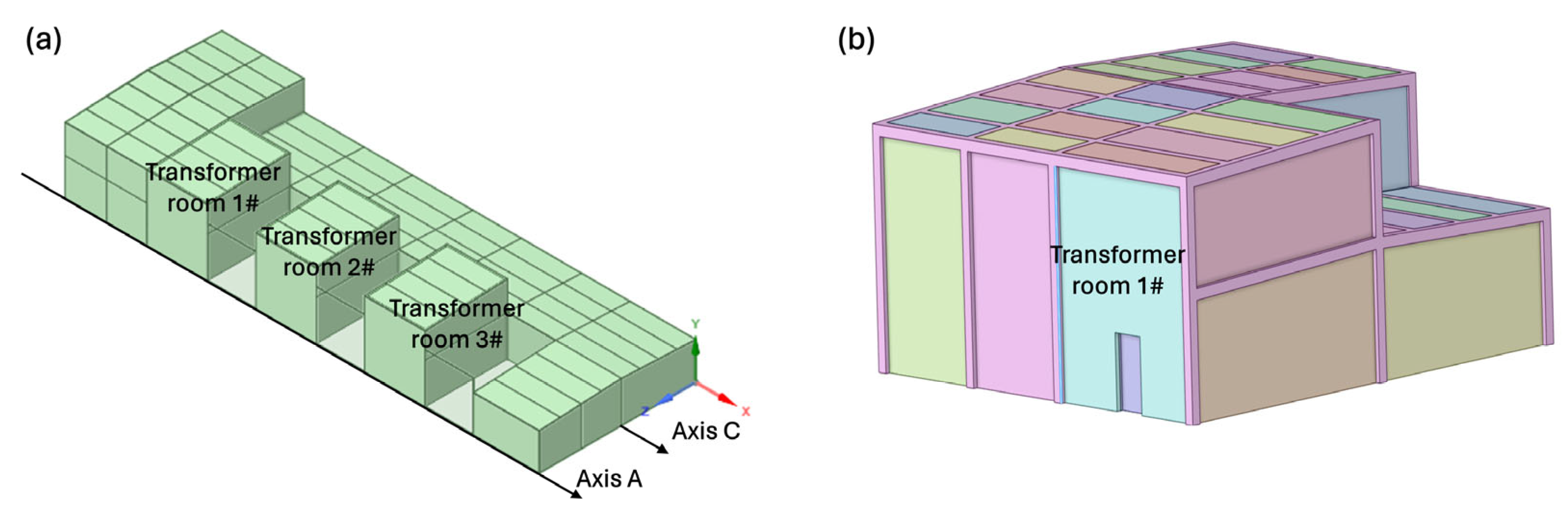
This study examined a 110 kV indoor steel frame substation with three physically identical transformer rooms. The 1# transformer room was designated as the representative case (Figure 1a), with the subsequent important structural parameters:
  • Structural specifications: The columns and beams of the frame are constructed from H-type steel, grade Q355B. Moreover, the transformer chamber features a column span of 7.5 m × 10.2 m. It is a double-height space with a sloped roof elevation ranging from 8.1 m to 8.6 m.
  • Wall assemblies: Exterior walls are composed of 100 mm thick fiber-reinforced cement siding paired with a 100 mm thick polystyrene granule cement composite board as an inner liner. This assembly provides a fire resistance rating of 3.0 h. Internal partitions are constructed from 150 mm thick polystyrene granule cement composite boards, also rated for 3.0 h. An integrated fireproof pressure-relief wall, with inspection doors, is positioned along the A-axis, while the other three sides are secured by firewalls or fire-rated doors. Simultaneously, an electrically powered double-layer waterproof aluminum alloy louver is installed on the C-axis at the second-story level for ventilation.
Notably, to balance computational cost with simulation accuracy, a simplified three-dimensional geometric model of the 1# transformer chamber and adjacent rooms was established (Figure 1b). The model retains the primary load-bearing steel skeleton, the volumetric representation of the transformer, and the essential spatial boundaries, while omitting secondary non-structural components.
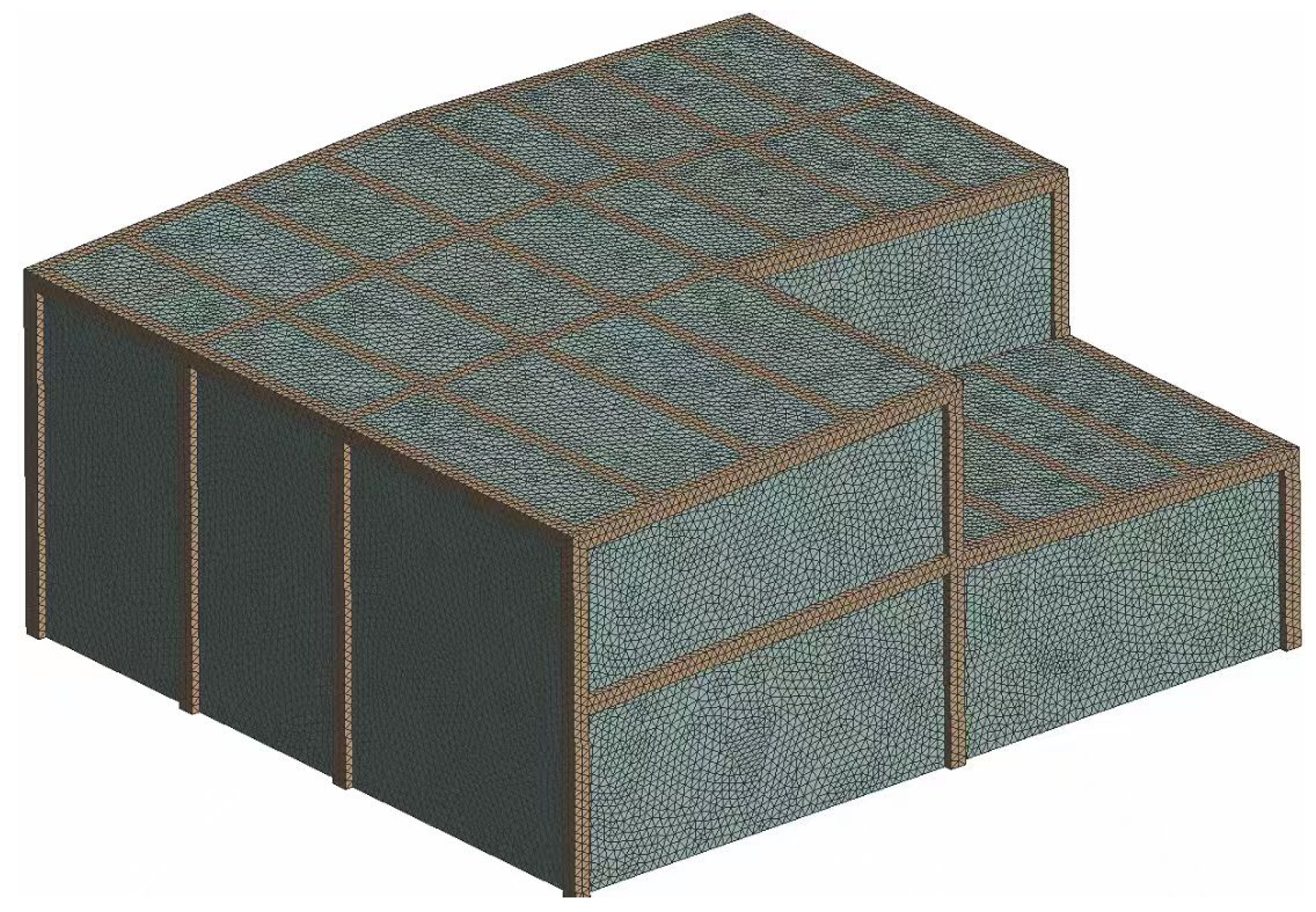
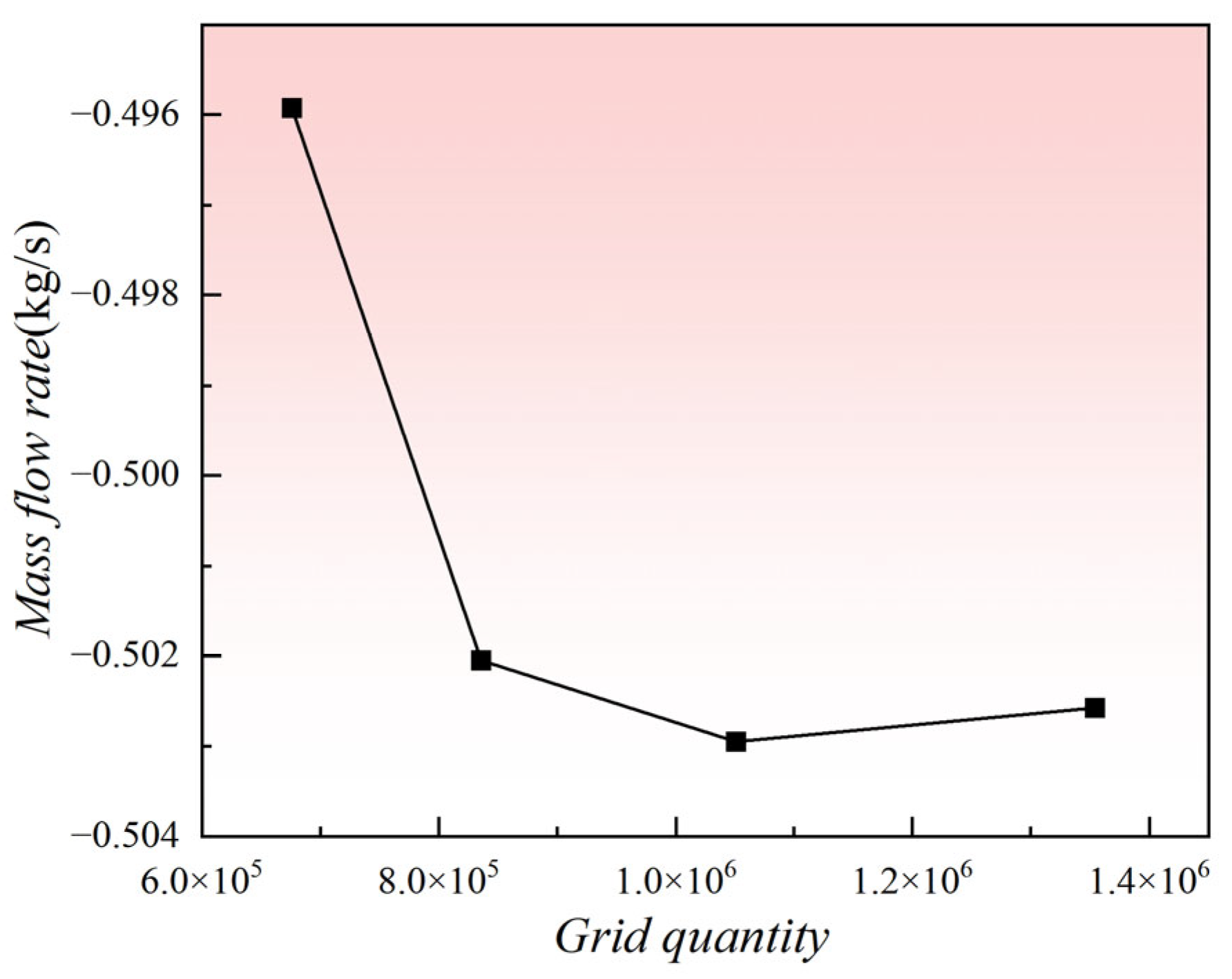
The computational domain was discretized using unstructured tetrahedral grids via ANSYS Mesh 2021. A grid independence study was conducted to ensure the solution’s insensitivity to mesh density. The final computational grid comprised approximately 194,600 elements with an average orthogonal quality of 0.816, satisfying the stringent requirements for numerical stability and convergence in transient CFD calculations (Figure 2). Furthermore, Figure 3 clearly shows that when the number of grid cells reaches approximately 1.05 million, the total mass flow rate at the outlet has essentially stabilized. Further increasing the grid density no longer significantly affects the computational results. Therefore, this study ultimately selected 1.05 million grid cells as the mesh configuration for subsequent numerical calculations.

2.2. Simulation of Fire Temperature Field

The simulation of the transformer fire is based on the combustion of transformer oil, a complex hydrocarbon mixture. The modeling approach utilizes ANSYS Fluent 2021 to solve the coupled non-linear partial differential equations governing fluid flow, heat transfer, and combustion. Based on the geometric model and mesh partitioning results established in Section 2.1, this section employs computational fluid dynamics (CFD) methods to construct a fire temperature field simulation system.

2.2.1. Mathematical Models and Governing Equations

The physical processes of the fire were described by the conservation laws of mass, momentum, energy, and species, augmented by models for turbulence and radiation.
Basic Conservation Equations
The equation for the conservation of mass in a compressible flow is (Mass Conservation):
ρ t + x i ( ρ u i ) = 0
where ρ is the fluid density, t is time, and u i is the velocity component in the i-direction.
The conservation of momentum accounts for fluid acceleration driven by pressure gradients, viscous forces, and body forces (Momentum Conservation):
t ( ρ u i ) + x j ( ρ u i u j ) = P x i + τ i j x j + ρ g i + F i
where P represents static pressure, τ i j is the viscous stress tensor, ρ g i denotes the gravitational body force (crucial for modeling buoyancy-driven smoke plumes), and F i represents external body forces such as drag from dispersed fuel droplets.
The energy equation governs the thermal field, balancing the rate of change in total energy against convection, diffusion, and heat sources (Energy Conservation):
( ρ E ) t + ( u ( ρ E + p ) ) = ( k e f f T ) + S
k e f f = k + k 1
where E is the total energy (internal + kinetic), k e f f is the effective thermal conductivity comprising the thermal conductivity k and the turbulent thermal conductivity k 1 , and S is the source term representing the heat released from chemical combustion.
Species Transport and Combustion Models
To model the mixing and reaction of fuel and oxidant, the transport equations for chemical species mass fractions Yi are solved (Species Transport Equation):
t ( ρ Y i ) + ( ρ u Y i ) = J i + R i + S i
where R i is the generation rate of the i-th component during the chemical reaction process (when no chemical reaction occurs, this term is set to zero); S i accounts for the source terms arising from the discrete phase and other external contributions; j i represents the diffusion flux of the i-th component.
Turbulence and Radiation Models
The flow regime in a large-scale fire is highly turbulent. The standard k-ε model was employed to close the Reynolds-averaged Navier–Stokes (RANS) equations. This model solves two transport equations: one for turbulent kinetic energy (k) and one for its dissipation rate (ε):
t ( ρ k ) + x i ( ρ k u i ) = x j μ + μ t σ k k x j + G k + G b ρ ε Y M + S k
t ( ρ ε ) + x i ( ρ ε u i ) = x j μ + μ t σ ε ε x j + C 1 ε ε k G k + C 3 ε G b C 2 ε ρ ε 2 k + S ε
These equations account for turbulence generation due to mean velocity gradients G k and, critically for fires, buoyancy ( G b ).
To accurately simulate the combustion behavior of transformer oil, this study employs a non-premixed combustion modeling framework in ANSYS Fluent. The interaction between turbulence and chemical reactions is described using the Finite-Rate/Eddy-Dissipation (FR/ED) model. Within this hybrid model, the actual reaction rate is determined by whichever mechanism—chemical kinetics or turbulent mixing—imposes the more restrictive constraint.
This modeling strategy is particularly well-suited for simulating hydrocarbon jet fires in substations, where such fires typically involve the coupled effects of rapid turbulent mixing and finite-rate chemical reactions.
For the combustion, the reaction rate was determined by the Finite Rate/Eddy Dissipation model or similar species transport formulations. The chemical reaction rate constant k was governed by the Arrhenius Law, linking reaction speed to temperature:
k = A r T n exp ( E a / R T )
where Ea is the activation energy. This relationship dictates that reaction intensity increases exponentially with temperature once the activation threshold is crossed.
For the radiation, in hydrocarbon fires, soot production makes radiative heat transfer the dominant mode of energy exchange. The Discrete Ordinates (DO) radiation model was selected for its ability to handle the full range of optical thicknesses and directional dependencies typical of fire environments. The Radiative Transfer Equation (RTE) solved is:
d I ( r , s ) d s + ( a + σ s ) I ( r , s ) = a n 2 σ T 4 π + σ s 4 π 0 4 π I ( r , s ) Φ ( s s ) d Ω
This equation describes the change in radiation intensity I along a path s due to absorption (a), scattering ( σ s ), and emission (related to T4).

2.2.2. Boundary Conditions and Solution Parameters

A transient formulation was utilized in this numerical simulation. The air intake and the transformer oil leaking source were designated as velocity inlet boundary conditions. The air entrance was designated a velocity of 0.2 m/s and a temperature of 293.15 K, whereas the oil leakage source was configured with a velocity of 0.3 m/s and a temperature of 358.15 K [25]. The default diesel-air model was employed to simulate species transport and chemical reactions, serving as a built-in simplified reaction mechanism for modeling the combustion of hydrocarbon fuels with air, while the DO radiation model was utilized with a wall emissivity of 0.96. The upper exit of the substation was designated as a pressure outlet boundary condition. The convergence criterion for all governing equation residuals was established at 1 × 10⁻⁶ to guarantee computational accuracy.

2.3. Sequential Thermal-Mechanical Coupling

Based on the transient temperature field results obtained in Section 2.2, this section further conducts sequential thermal-mechanical coupling structural analysis to evaluate the response behavior of critical steel members under actual fire conditions. It analyzes the deformation evolution and load-bearing capacity degradation process of steel structures in fire environments. Following the CFD simulation, the structural response was analyzed using Abaqus. A sequential coupled thermal-stress analysis methodology was adopted. This approach is predicated on the assumption that while temperature changes induce significant stress and deformation in the structure (via thermal expansion and material degradation), the deformation of the structure has a negligible effect on the thermal field itself (one-way coupling).

2.3.1. Coupling Methodology

The transient temperature history of the fluid surrounding the steel structure, obtained from the Fluent simulation, was applied in Abaqus by defining it as an ambient air temperature curve for the heat transfer analysis. Subsequently, the resulting temperature field of the steel structure was used as the thermal load input for the sequential thermo-mechanical coupling analysis. Additionally, the mechanical solver calculated the resulting strains, stresses, and displacements at each time increment, accounting for thermal expansion and the temperature-dependent reduction in material stiffness and strength.

2.3.2. Structural Model and Material Constitutive Laws

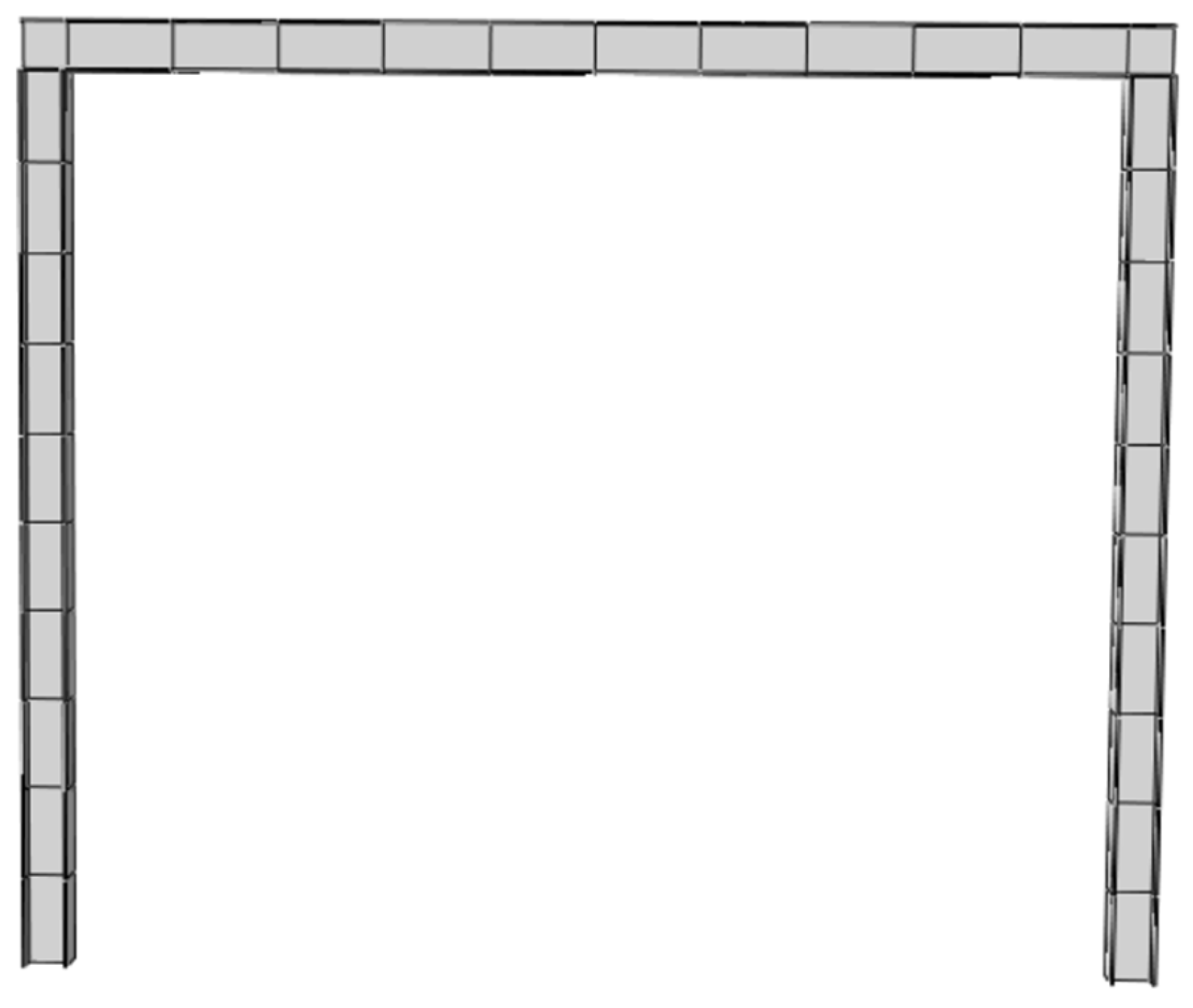
The structural analysis focused on a local sub-model of the steel frame, specifically the middle-span steel beam (H450 × 250 × 12 × 16, Q355B) and its supporting columns, as this component bears the highest risk of flexural failure (Figure 4). The column base of the steel frame is hinged, and tie contact is set between components. Although GB/T 9978.1-2008 itself is a normative test method based on standard fire curves, the failure criterion it specifies—maximum deflection of the member reaching L/30, i.e., 355 mm—as the ultimate limit state for structural loss of load-bearing capacity has certain applicability [26]. Therefore, this study adopts this ultimate displacement as the mechanical criterion for assessing structural failure in natural fire scenarios. The failure criterion for plastic strain is defined as the equivalent plastic strain being less than 0.2.
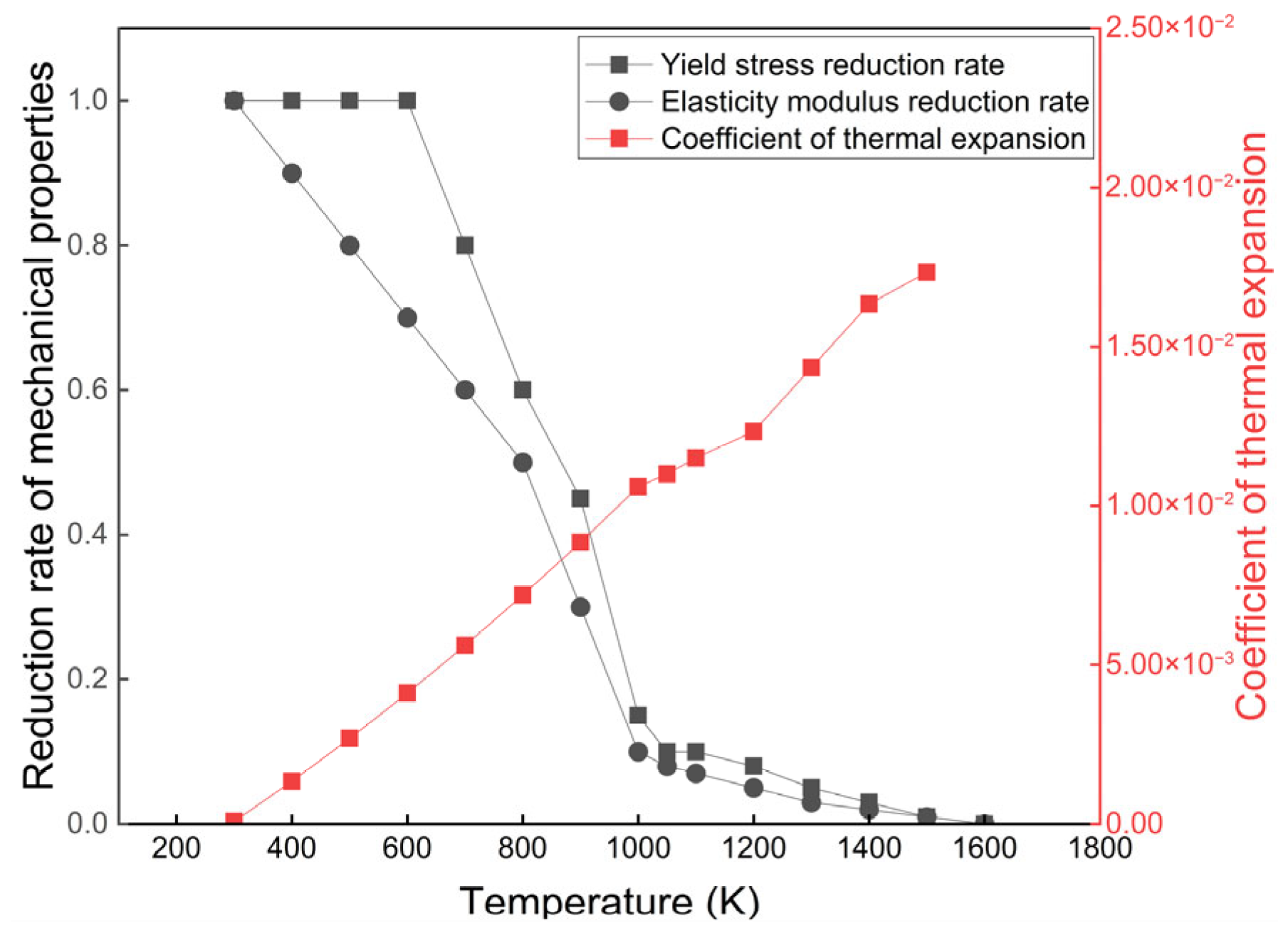
Regarding thermal boundary conditions, convective heat transfer coefficients of 50 W/(m2·K) and 9 W/(m2·K) were applied to the fire-exposed and unexposed surfaces, respectively. The use of 50 W/(m2·K) for the fire-exposed surface is based on the recommendation for hydrocarbon fire exposure in EN 1991-1-2, representing a relatively conservative assumption [27]. Although a lower value (e.g., approximately 35 W/(m2·K)) could also be justified by CFD-based natural fire models, adopting 50 W/(m2·K) favors conservative (safe-side) predictions. The mechanical properties of the Q355B steel (elastic modulus and yield strength) were defined as non-linear functions of temperature, strictly adhering to the European Standard EN 1993-1-2 [28]. As illustrated in Figure 5 of the source document, the material properties exhibit a precipitous decline between 700 K and 1000 K, effectively reaching zero strength near 1500 K.

2.3.3. Loading Criteria

A uniform line load of 27.44 kN/m was applied to the beam. This value represents the design load combination for the fire limit state, including permanent dead loads, roof live loads, snow loads, and wind loads. Verification confirmed that the beam satisfies all stress and deflection requirements under ambient temperature conditions.

2.3.4. Fireproof Coating Parameters

To evaluate the effectiveness of passive fire protection, the simulation modeled the application of two proprietary non-intumescent fireproof coatings, designated Material A and Material B. These were modeled as solid layers perfectly bonded to the steel substrate (ignoring contact thermal resistance). The thermophysical properties and thickness configurations are detailed in Table 1. It should be noted that although the thermal properties (thermal conductivity, specific heat, and density) of such materials typically vary significantly with temperature under real fire conditions, this study assumes constant thermophysical parameters at elevated temperatures for engineering simplification, using the thermal conductivity at an intermediate temperature as a reference value. This simplification may lead to incomplete accuracy in predicting the fire resistance of protected steel members and may have certain limitations, but it is considered acceptable.

3. Results and Discussion

3.1. Analysis of Fire Dynamics and Temperature Field Evolution

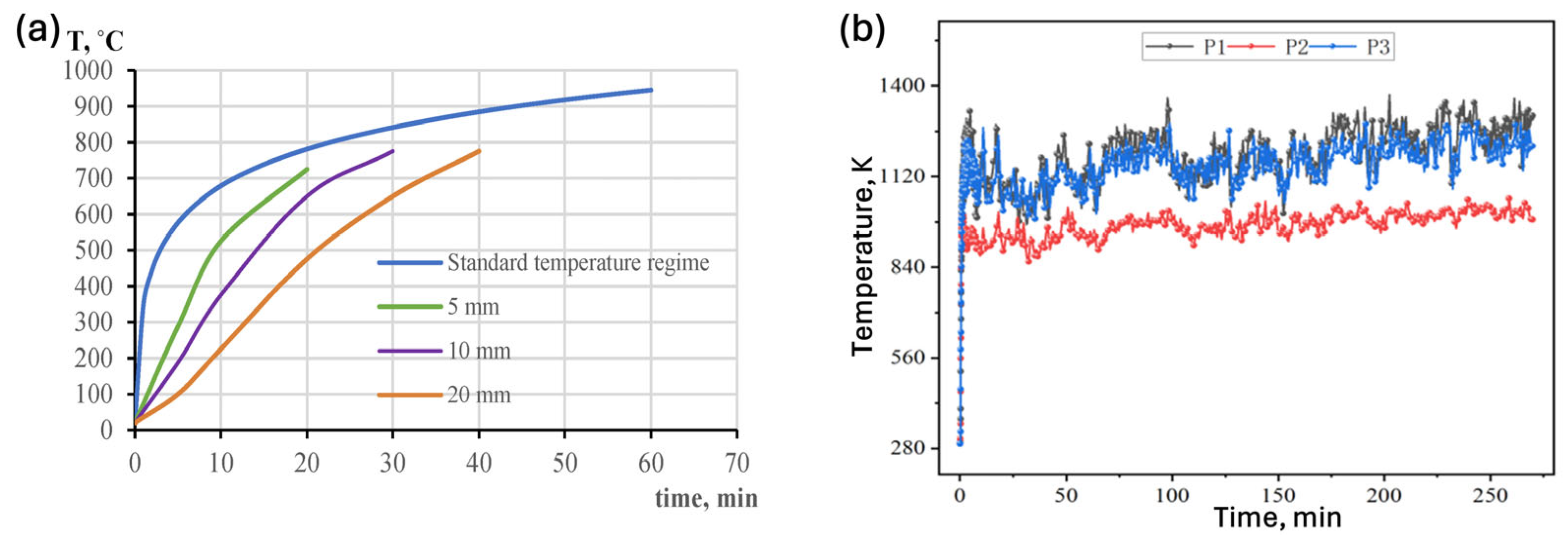
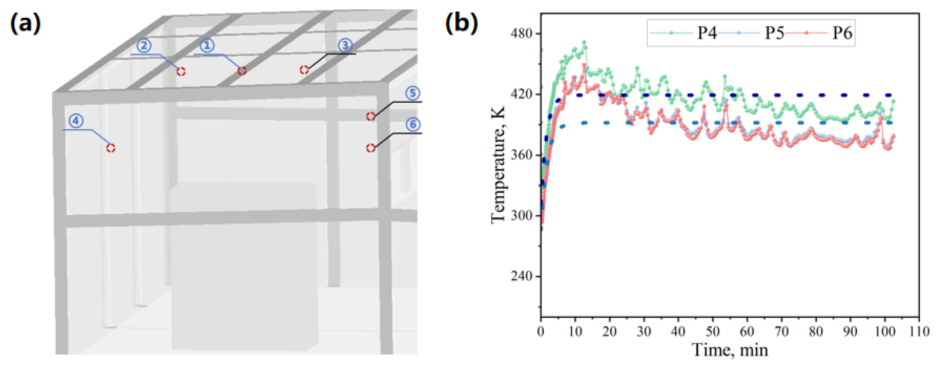
The CFD simulation results for the globally averaged temperature rise within the transformer chamber were compared against standard empirical correlations for hydrocarbon fires to validate the model’s accuracy. The comparison (Figure 6) reveals a high degree of concordance in the heating rate and general trend. Moreover, Figure 7b similarly demonstrates this characteristic. And the distribution of relevant points is shown in Figure 7a.

3.1.1. Temperature Field Evolution

The simulated temperature profile exhibited three distinct phases: (1) Initial growth phase: Upon ignition, the temperature rose explosively. This is attributed to the presence of a fuel-rich mixture and ample oxygen near the leak source, leading to a localized deflagration or “flash” combustion. (2) Transition phase: Following the initial spike, a slight decrease in temperature was observed. This phenomenon likely resulted from the rapid consumption of local oxygen and the transition of the combustion regime from pre-mixed/efficient burning to a diffusion-limited steady state. Additionally, as the fire plume established, entrainment of cooler air regulated the core temperature. (3) Steady-state phase: As the fire developed, a dynamic equilibrium was reached between the heat release rate of the burning oil, the intake of fresh air through vents, and the heat losses through the building envelope.
The findings aligned with those of Sun et al. [3], who indicated that in transformer oil jet fires, the flame progresses from the growth phase to the attenuation phase as the availability of combustible materials decreases, resulting in a temperature peak followed by a progressive reduction.

3.1.2. Spatial Thermal Stratification

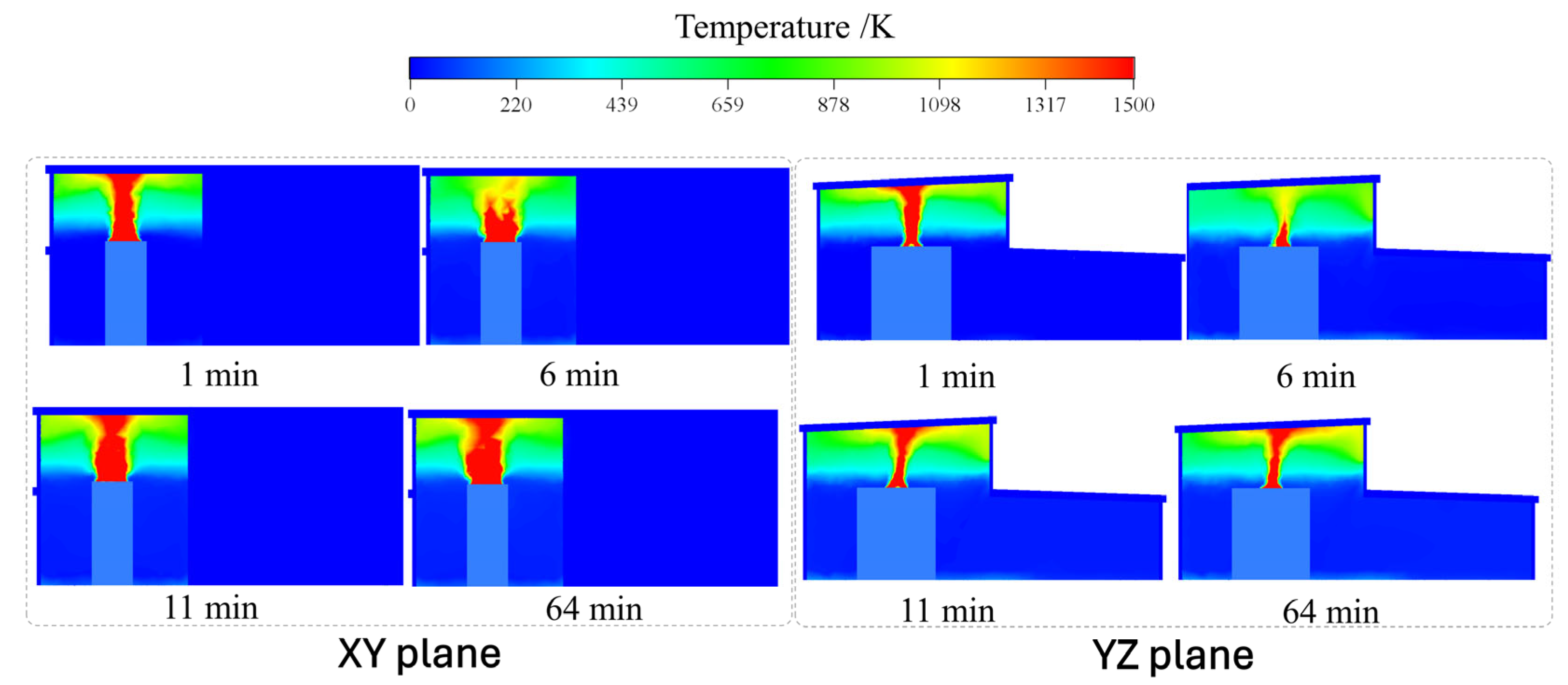
The spatial temperature distribution within the chamber (Figure 8) demonstrated a significant thermal stratification or “chimney effect” typical of fires in high-ceilinged spaces. A high-temperature core was situated just above the burning oil jet when convective and radiative heat fluxes were at their peak. Furthermore, propelled by buoyancy, hot combustion gases and soot ascend swiftly to the roof. Unable to leave promptly, they coalesced to create a stable, high-temperature smoke layer that occupied the upper volume of the substation. As a result, the steel roof trusses and the upper flanges of the portal frames were perpetually submerged in this heated gas layer. The simulation shows that these higher structural elements are exposed to intense thermal radiation from the flame zone exceeding 1500 K, while the surrounding hot gas layer maintains temperatures in the range of 800–1100 K throughout the fire duration. This combined thermal exposure leads to rapid heating of critical structural members. Certain components within the superstructure experience intermittent or sustained direct exposure to high temperatures within the flame zone, resulting in extremely high local surface heat flux densities that cause rapid temperature rise in these specific areas. Simultaneously, the entire upper space is enveloped by a high-temperature smoke layer (typically ranging from 800 to 1100 K), which continuously heats all upper components through convection and radiation.

3.1.3. Distribution of Combustion Products

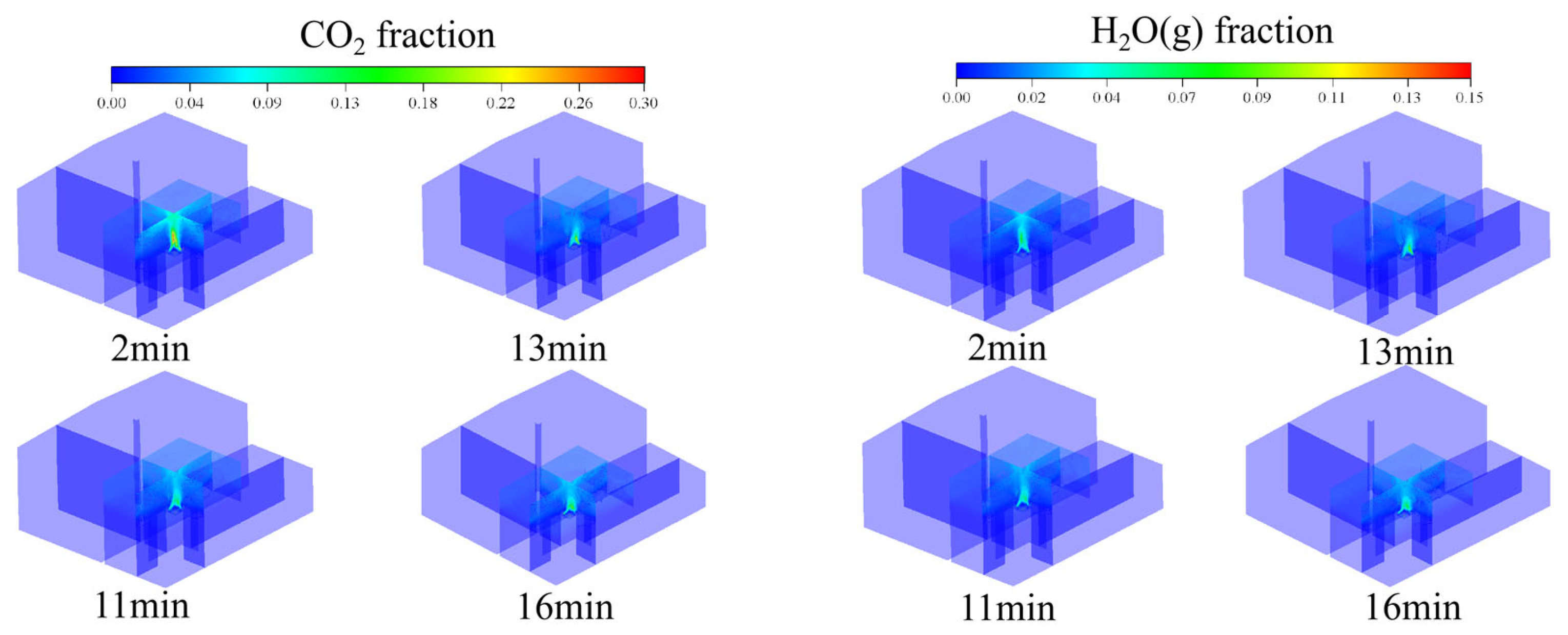
The distribution of chemical species, specifically CO2 and water vapor (H2O), closely correlated with the thermal field (Figure 9). In the initial phase, a localized zone of high CO2 and H2O concentration followed the trajectory of the initial jet flame. During the initial stage of fire development, the peak volume fraction of CO2 near the roof was approximately 0.06–0.08, while that of H2O was about 0.05–0.07. Subsequently, as the fire stabilized, combustion products accumulated significantly in the upper regions of the chamber (The space approximately 0.7 m below the roof). During the late stage of the fire, the distribution of combustion products within the upper smoke layer stabilized. The volume fraction of CO2 remained consistently high at around 0.14, reaching nearly 0.22 in localized areas, while the volume fraction of H2O maintained a range of 0.12–0.15. The high concentration of CO2 at the roof level reinforced the finding that the upper steel structure was situated in a chemically reactive and thermally extreme environment. The presence of these triatomic gases (CO2, H2O) further enhanced the radiative heat transfer to the structure due to their substantial emissivity at high temperatures.
It should be noted that the presence of high concentrations of CO2 and H2O in combustion products not only affects smoke distribution characteristics but also directly influences the thermal behavior of structural elements. In high-temperature fire environments, CO2 and H2O are typical highly radiative gases. As their concentrations increase, the effective emissivity of the smoke layer significantly rises, thereby amplifying radiative effects.
In substation environments, once a fire reaches its steady state, a high-temperature smoke layer forms at the upper level. The CO2 and H2O within this smoke layer not only absorb radiant energy from the flames but also re-emit radiant energy toward surrounding structural surfaces, creating a substantial net radiative heat flux input. Compared to pure convective heat transfer mechanisms, radiative heat transfer contributes more significantly to the temperature rise in high-temperature steel structures. This effect becomes particularly pronounced when gas temperatures exceed 1000 K, causing the proportion of radiative heat flux to increase rapidly.
Therefore, the accumulation of high concentrations of CO2 and H2O accelerates the temperature rise and mechanical property degradation of steel by enhancing the effective emissivity of the smoke layer and increasing the radiative heat load on steel surfaces.

3.1.4. Thermal Response of Steel Members

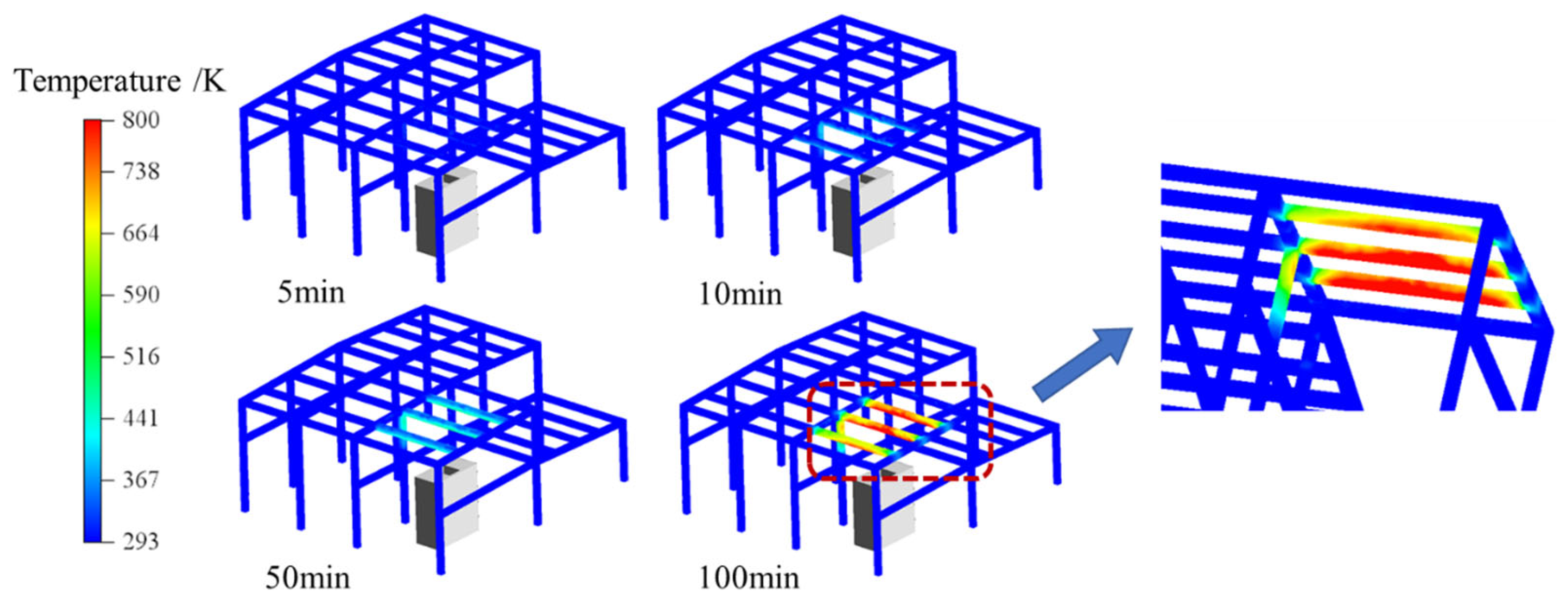
The thermal response of the steel members (Figure 10) exhibited a lag relative to the gas temperature due to the thermal inertia of the material. In the early stages, the steel temperature remained relatively low as the fire plume developed. As the gas temperature stabilized at 1500 K, the steel absorbed heat via convection and radiation. The temperature of unprotected steel members increased continuously.
The simulation shows that regions of the steel frame directly above the fire source reach localized temperatures of 800 K. Once the fire enters its sustained development phase, the ambient temperature continues to rise and remains at 800–1000 °C or even higher. Although the critical temperature of steel frames is primarily determined by factors such as the load ratio and restraint conditions of the components, under the medium load ratio conditions commonly used in engineering, the steel temperature can still gradually reach its critical value (typically around 500 °C [30]). Furthermore, the local maximum temperature above the fire source can reach 800 K, and the surrounding steel structural connections also gradually heat up due to the effects of heat conduction. At this stage, the mechanical properties of the steel structure significantly deteriorate, with strength reduced to approximately 50% of its initial value. This degradation may lead to overall structural instability or collapse.

3.2. The Thermal Mechanical Response of Steel Structures

3.2.1. Thermo-Mechanical Response of Unprotected Structures

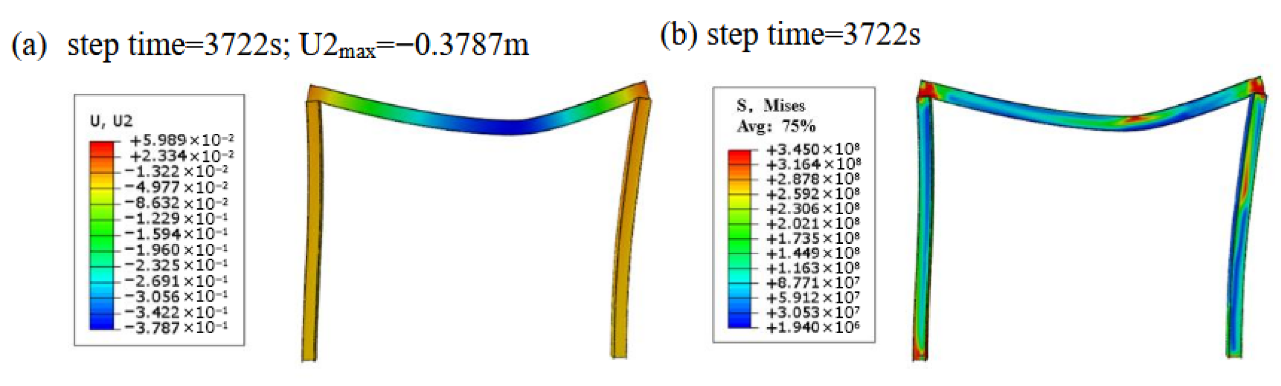
In terms of deformation and failure, the unprotected steel beam demonstrated a swift deterioration of structural integrity under the simultaneous influence of the mechanical design load (27.44 kN/m) and the thermal load resulting from the fire simulation. The progression of vertical displacement at the beam’s mid-span (Figure 11a) exhibited a non-linear runaway tendency. The initial deflection was caused by thermal expansion. When the temperature increases, nonetheless, the modulus of elasticity of the steel deteriorates markedly. The reduction in stiffness resulted in a fast escalation of mechanically induced deflection.
Specifically, at t = 3722 s (roughly 62 min), the vertical displacement at mid-span attained 378.7 mm. This value surpassed the code-specified failure threshold of 355 mm (see Section 2.3.1). Therefore, the unprotected structure was said to have attained its ultimate limit state and subsequently failed. The deformation profile demonstrates a peak at the mid-span, diminishing towards the supports, which aligns with the characteristics of a simply supported beam experiencing plastic hinge development under thermal loading.
Concerning stress distribution and concentration, the von Mises stress distribution at the moment of failure (Figure 11b) highlighted the mechanisms of collapse. For example, significant stress concentrations were observed in the lower flange of the beam, directly in the zone of flame impingement. The peak stress in these regions reached 345 MPa. Moreover, referring to the temperature-dependent material properties of Q355B steel (Figure 5), at a temperature of 800 K, the yield strength reduced to ~248 MPa.
In conclusion, the calculated stress (345 MPa) far exceeded the reduced yield strength (248 MPa) of the material at that temperature. This confirms that the bottom flange has yielded and entered the plastic deformation range. The inability of the yielded section to sustain the bending moment leads to the redistribution of forces and eventual structural instability. This analysis quantitatively confirms that unprotected steel structures possess insufficient fire resistance to withstand hydrocarbon transformer fires.

3.2.2. Verification of Fire Resistance Performance of Coating Materials

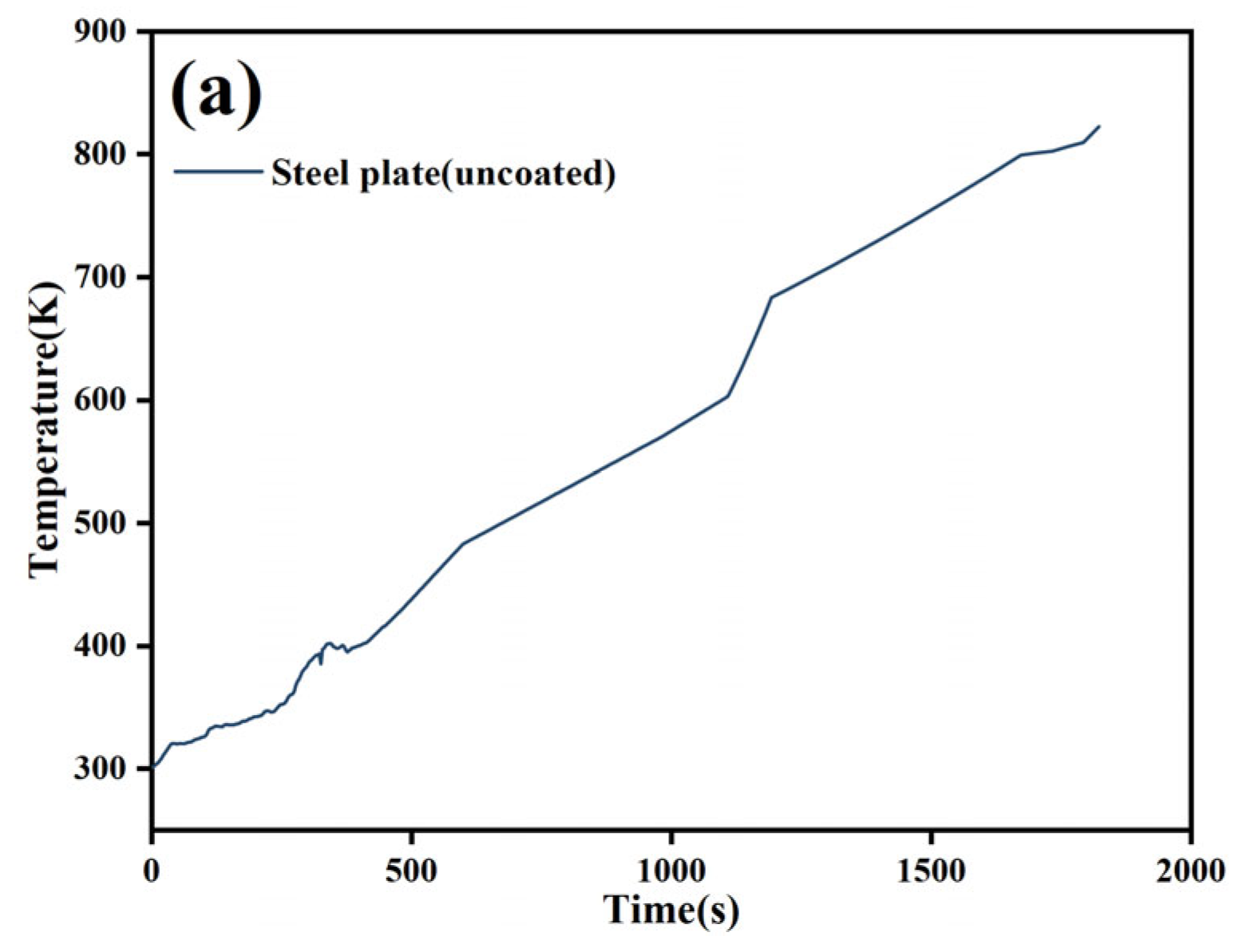
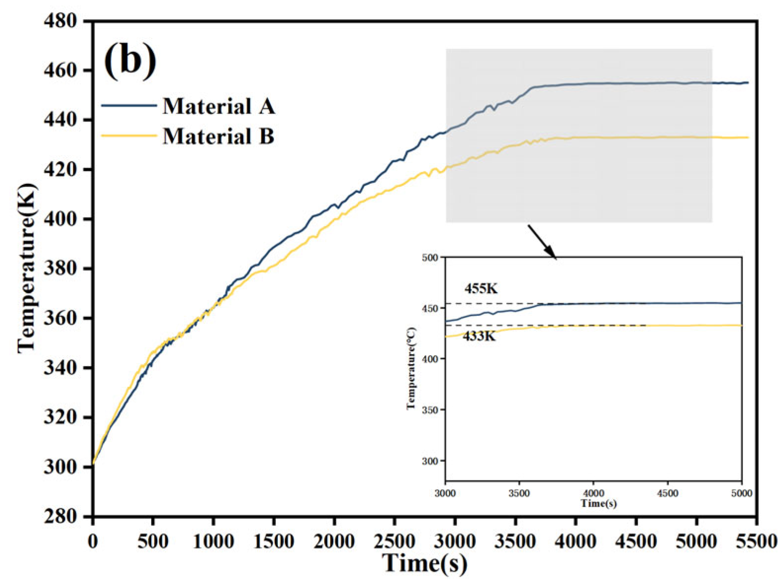
Fire-resistant coatings ensure the integrity of steel structures by blocking heat transfer, and the temperature on the non-fire-exposed side serves as a direct indicator of their thermal insulation performance. Figure 12b showed the temperature change on the non-fire-exposed side of steel structures protected by 10 mm-thick Material A and Material B. Compared to uncoated steel (Figure 12a, where the monitored temperature rose up to ~800 K, which was consistent with the modeling result shown in Figure 10), both coatings exhibited a trend where the temperature initially rose before stabilizing. However, Material B, which had a lower thermal conductivity, exhibited a slower rate of temperature rise and a lower stabilized temperature, demonstrating significantly superior thermal protection compared to Material A of the same thickness. It could effectively delay the temperature rise and mechanical property degradation of the steel, substantially extending the fire resistance limit of the steel structure, fully confirming that reducing the thermal conductivity of the coating is the key approach to enhancing the fire resistance of steel structures in substations.

3.3. Evaluation of Fire Protection Effectiveness

To mitigate the rapid failure observed in the unprotected scenario, passive fire protection is essential. This section evaluates the sensitivity of the structure’s survival time to coating thickness and material properties.

3.3.1. Impact of Coating Thickness

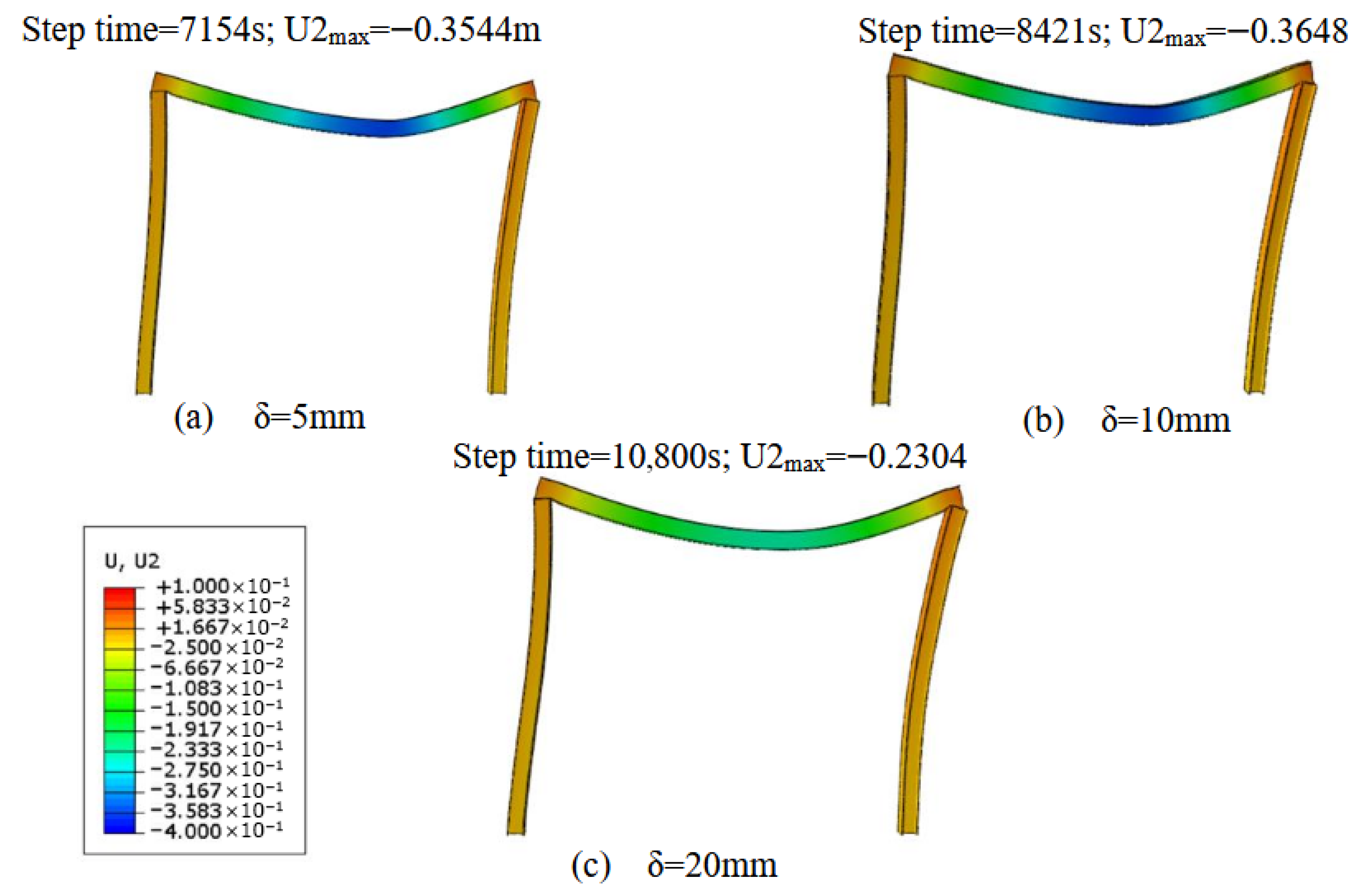
Material A represents a standard fire-retardant coating with a thermal conductivity of λ = 0.20 W/(m·K). The analysis results (Figure 13) demonstrated a non-linear relationship between coating thickness and fire resistance time.
The application of a thin 5 mm layer extended the time to failure (displacement = 355 mm) from 4825 s to 9390 s. This represented a 95.8% increase in fire resistance time. While a significant improvement, 9390 s (~2.6 h) falls short of the typical 3 h (10,800 s) fire rating requirement for critical substation infrastructure. Sequentially, augmenting the thickness to 10 mm prolonged the failure duration to 9900 s. The incremental gain (510 s increase for doubling the thickness from 5 to 10 mm) signifies declining returns for this particular material’s conductivity within the intermediate thickness range. This indicates that heat ultimately saturates the covering, rendering conduction the predominant mechanism of transfer.
A critical performance threshold was crossed with a 20 mm application. Under this condition, the maximum mid-span displacement stabilized at 160.4 mm for the entire 3 h (10,800 s) simulation duration. This is well below the 355 mm failure limit (Figure 13c).
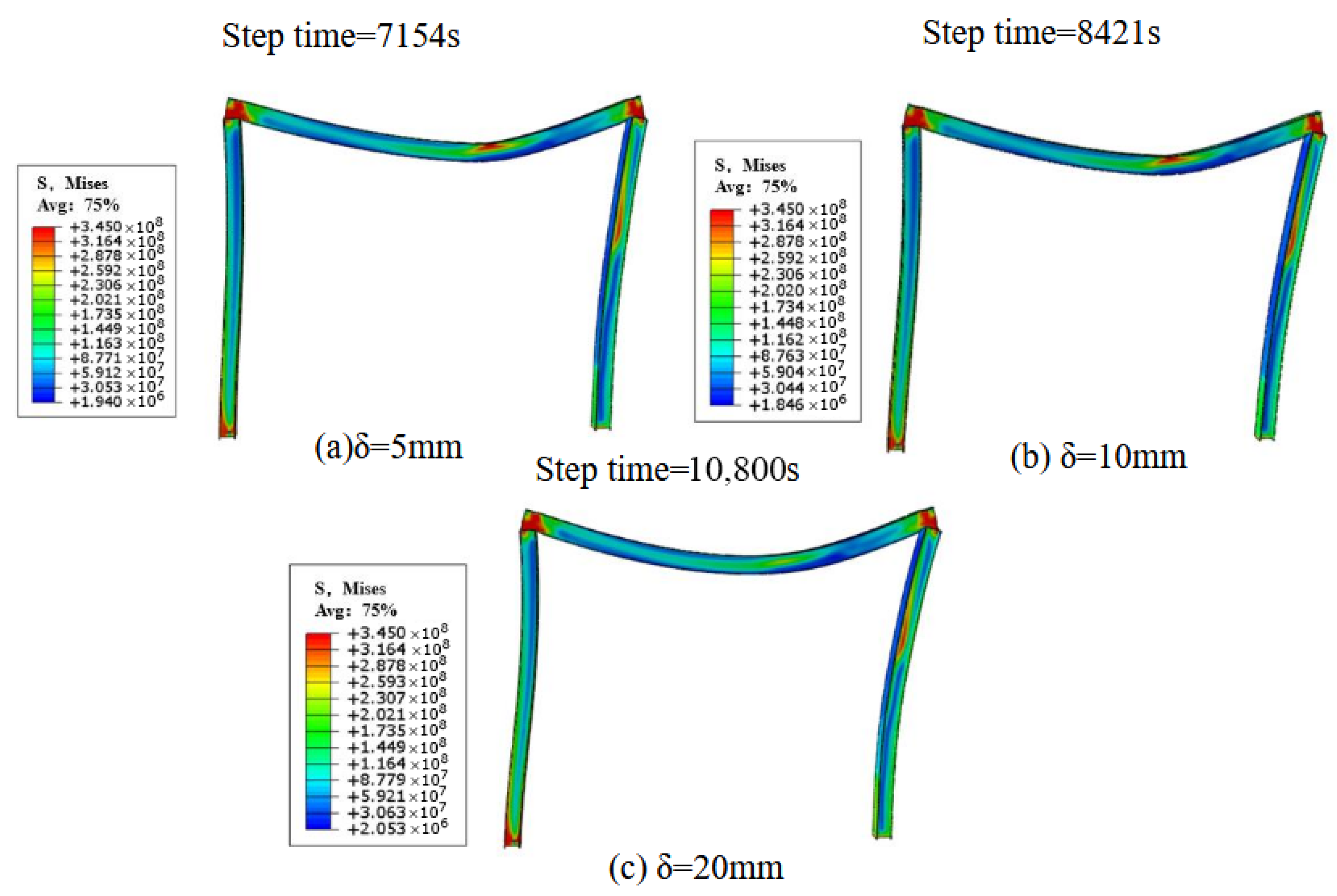
Additionally, Figure 14 illustrates the stress field distributions of steel beams associated with varying coating thicknesses. At coating thicknesses of 5 mm and 10 mm, the maximum stress at structural failure attained 345 MPa. Conversely, increasing the coating thickness to 20 mm significantly mitigated the high stress concentration previously reported in the node regions under thinner coatings. The stress distribution became more uniform, with most places maintaining stress levels below the 248 MPa yield strength barrier, indicating effective preservation of the structural load-bearing capability. The results indicate that augmenting the thickness of fireproof coating material A enhances thermal insulation, reduces the rise in steel temperature, postpones the deterioration of mechanical characteristics, and so considerably improves structural fire resistance performance.

3.3.2. Impact of Material Properties

The study further investigated the efficacy of Material B, a high-performance insulating material characterized by a lower thermal conductivity (λ = 0.10 W/(m·K)), lower density, and higher specific heat capacity than Material A.
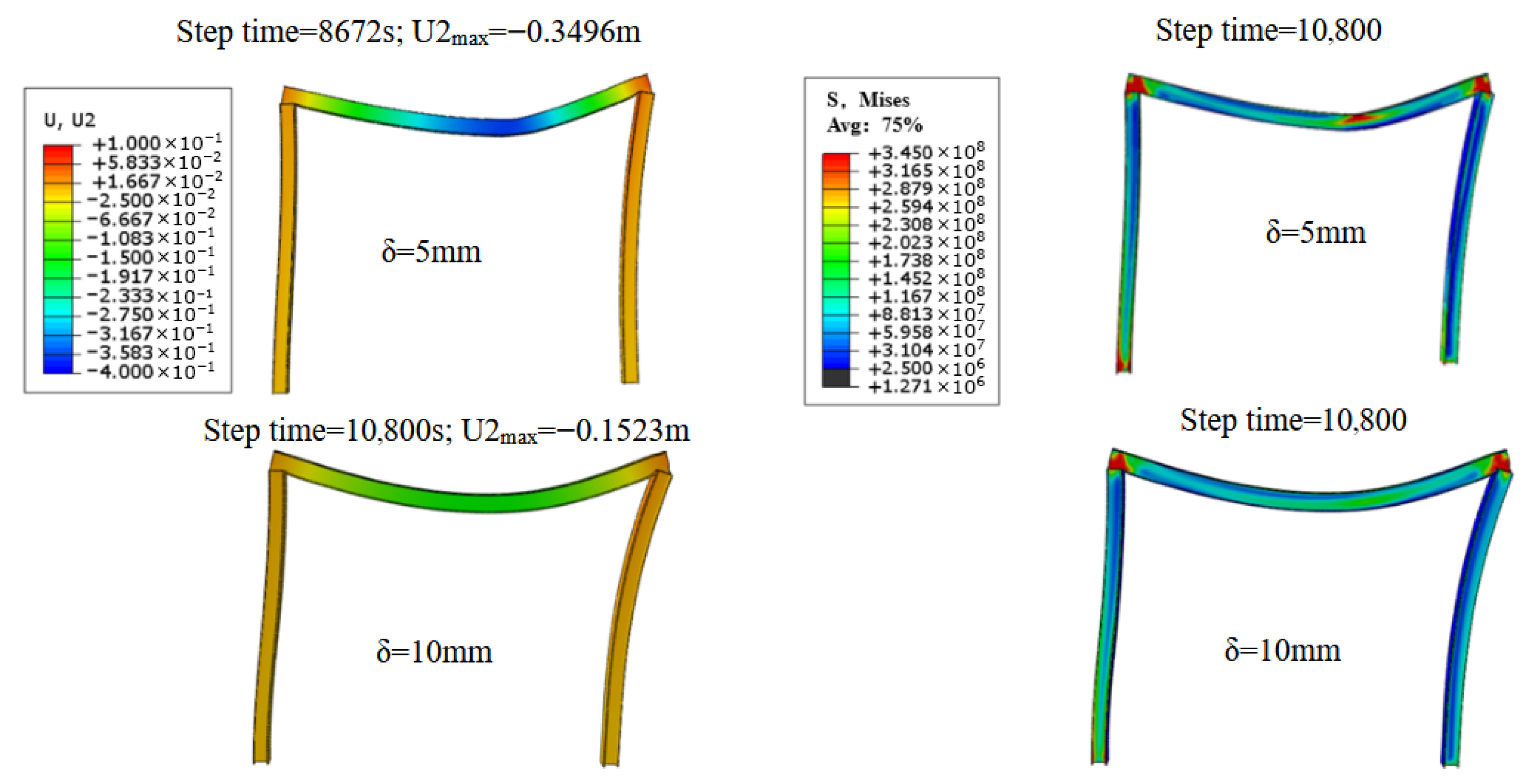
Even at a thin application of 5 mm, Material B significantly outperformed Material A. The beam survived 8672 s (about 144 min). The maximum displacement reached 349.6 mm, which is very close to the strict safety limit of 355 mm (Figure 15). This highlights that thermal conductivity is one of the key parameters. Lowering the thermal conductivity directly and substantially improves the fire resistance period of steel members.
Increasing Material B to 10 mm provided superior protection. The maximum mid-span displacement was limited to just 152.3 mm after 3 h. This performance was better than even the 20 mm layer of Material A (which resulted in 230.4 mm displacement). The stress levels in the beam remain negligible relative to the material’s yield strength.
Overall, the protective function of fireproof coatings for steel structures is mostly accomplished by retarding the rate of temperature increase in steel, therefore postponing the deterioration of its mechanical qualities. Enhancing coating thickness and diminishing thermal conductivity can significantly augment thermal insulation efficacy and prolong the structure’s fire resistance threshold. From an engineering perspective, in spatially restricted situations like substations or where sensitivity to additional structural stresses is critical, the use of low-thermal-conductivity fireproof coating material B is advisable. This method significantly improves fire-resistant performance without augmenting coating thickness or structure weight, providing notable technological benefits and practical value. When coating thickness is not severely constrained, and cost efficiency is paramount, a slight increase in coating thickness offers a financially advantageous approach to enhancing fire protection. This study provides a theoretical framework for the design and safety evaluation of fireproof coatings in steel structures of substations by systematically analyzing the impact of coating thickness and material parameters on the thermal-mechanical coupling response.
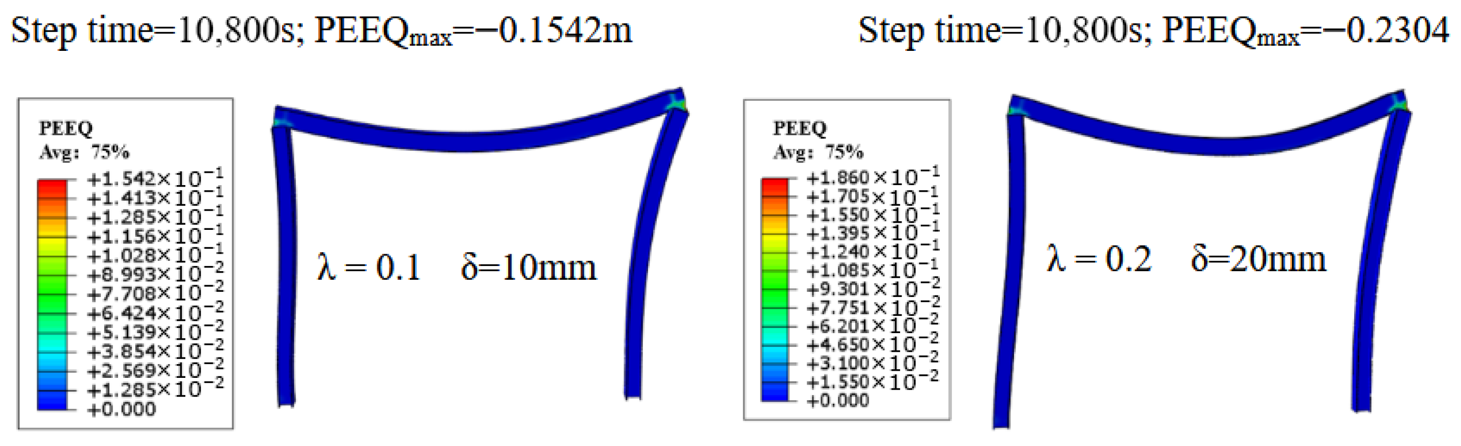
Figure 16 illustrates the equivalent plastic strain contours for two configurations in which the vertical displacement remained within the acceptable limit (i.e., did not exceed the failure criterion): one with a thermal conductivity of 0.20 W/(m·K) and a thickness of 20 mm, and the other with a thermal conductivity of 0.10 W/(m·K) and a thickness of 10 mm. As shown, after achieving the target fire resistance duration of three hours, the maximum equivalent plastic strains reached 0.1542 and 0.1860, respectively. Both values remain below the failure threshold of 0.2. Notably, the configuration with the lower thermal conductivity (0.10 W/(m·K)) and reduced thickness (10 mm) exhibits superior performance, as indicated by its lower maximum equivalent plastic strain under the same fire exposure conditions.

4. Conclusions

This study investigated hydrocarbon fires initiated by 110 kV substation transformers. A coupled numerical model integrating Fluent and Abaqus was developed to systematically analyze the temperature field evolution, thermal-mechanical response characteristics, and protective performance of two non-intumescent fireproof coatings (Material A and Material B) in steel structures under fire exposure. The following conclusions are drawn:
  • During fire development, a pronounced temperature stratification was observed within the substation. Combustion products such as CO2 rose with hot airflows and accumulated at the ceiling, forming a stable high-temperature smoke layer that continuously heated the upper enclosure. As a result, the top-mounted steel structures remained exposed to extreme temperatures of ~1500 K for extended durations.
  • Steel components near the fire source experienced progressive temperature increase due to direct thermal exposure, with local temperatures reaching up to 800 K. This led to significant degradation of their mechanical properties. In the absence of coating protection, high stress and large deformations were concentrated in the directly exposed regions. The maximum mid-span vertical displacement of the steel beam exceeded the load-bearing limit of 355 mm, leading to structural failure within a relatively short time frame.
  • The application of non-intumescent fireproof coatings substantially improved the thermo-mechanical behavior of steel structures during fire events by effectively retarding heat transfer and delaying temperature rise, thereby extending the fire resistance period. Applying 20 mm-thick Material A (equivalent thermal conductivity: 0.20 W/(m·K)) or 10 mm-thick Material B (lower equivalent thermal conductivity: 0.10 W/(m·K)) effectively mitigated thermal stress concentration at critical locations. Both configurations ensured that structural deformation remained within the safety threshold throughout the full 3 h fire exposure duration, preserving structural integrity and load-bearing capacity.
  • It should be noted that while numerical results indicate fireproof coatings significantly enhance the fire resistance of steel structures, their engineering application requires comprehensive consideration of potential risks and limitations. First, thicker coatings increase material and construction costs, potentially imposing significant economic burdens on large-scale substation structures. Second, the additional weight of the coating increases the structure’s dead load, necessitating re-verification of member load-bearing capacity and stability during the design phase. Additionally, practical implementation may encounter issues such as uneven coating thickness, localized voids, or material performance degradation during long-term service, all of which could compromise actual protective efficacy. Therefore, the proposed protective scheme should undergo comprehensive optimization—balancing fire resistance requirements with economic analysis, structural load-bearing verification, and long-term maintenance strategies. Future research could further integrate life-cycle cost assessment and durability analysis to enhance the engineering applicability of fire protection design solutions.
This study confirms the necessity of using advanced coupled simulation techniques to capture the true behavior of structures in industrial fires, providing a verified, data-driven framework for the fire safety design of critical electrical infrastructure.

Author Contributions

L.Q.: Conceptualization, Methodology, Data curation; Z.Z. (Zheng Zhou): Investigation, Data curation; W.O.: Investigation, Writing—original draft; Y.Z.: Conceptualization, Methodology; J.H.: Investigation, Writing—original draft; Z.Z. (Zhoufeng Zhao): Conceptualization; H.L.: Conceptualization, Supervision, Writing—review and editing. K.L.: Methodology. S.J.: Supervision, Funding acquisition. All authors have read and agreed to the published version of the manuscript.

Funding

This work was financially supported by the Science and Technology Project of State Grid Zhejiang Electric Power Co., Ltd. (5211DS250005).

Institutional Review Board Statement

Not applicable.

Informed Consent Statement

Not applicable.

Data Availability Statement

The raw data supporting the conclusions of this article will be made available by the authors on request.

Conflicts of Interest

Authors Lvchao Qiu, Zheng Zhou, Yutong Zhou, Zhoufeng Zhao and Kuangda Lu were employed by the company State Grid Zhejiang Electric Power Research Institute. The remaining authors declare that the research was conducted in the absence of any commercial or financial relationships that could be construed as a potential conflict of interest. The authors declare that this study received funding from the Science and Technology Project of State Grid Zhejiang Electric Power Co., Ltd. The funder was not involved in the study design, collection, analysis, interpretation of data, the writing of this article or the decision to submit it for publication.

References

  1. Guo, X.; Ding, L.; Ji, J. Method for Fire Risk Assessment of Urban Power Substation Considering Data Uncertainty. Fire Technol. 2025, 61, 5291–5317. [Google Scholar] [CrossRef] [Scilit]
  2. Shi, S.; Liu, G.; Li, Z.; Ye, X. Elevation-Dependent Growth Trends of Forests as Affected by Climate Warming in the Southeastern Tibetan Plateau. For. Ecol. Manag. 2021, 498, 119551. [Google Scholar] [CrossRef] [Scilit]
  3. Sun, R.; Wang, J.; Yang, X.; Chen, P. Experimental Research on the Combustion Characteristics of Transformer Oil Jet Fires in Oil-Filled Equipment under Heat. ACS Omega 2021, 6, 31843–31853. [Google Scholar] [CrossRef] [Scilit] [PubMed]
  4. Wu, C.; Zhou, T.; Chen, B.; Liu, Y.; Liang, P. Experimental Study on Burning Characteristics of the Large-Scale Transformer Oil Pool Fire with Different Extinguishing Methods. Fire Technol. 2021, 57, 461–481. [Google Scholar] [CrossRef] [Scilit]
  5. Mashhadimoslem, H.; Ghaemi, A.; Behroozi, A.H.; Palacios, A. A New Simplified Calculation Model of Geometric Thermal Features of a Vertical Propane Jet Fire Based on Experimental and Computational Studies. Process Saf. Environ. Prot. 2020, 135, 301–314. [Google Scholar] [CrossRef] [Scilit]
  6. Harmathy, T.Z. Effect of Moisture on the Fire Endurance of Building Elements; Research Paper; National Research Council of Canada, Division of Building Research: Ottawa, ON, Canada, 1965; p. DBR-RP-270. [CrossRef]
  7. Jiang, B.; Wang, M.; Shen, Y.; Li, Y. Robustness Assessment of Planar Steel Frames Caused by Failure of a Side Column under Localized Fire. Struct. Des. Tall Spec. Build. 2020, 29, e1711. [Google Scholar] [CrossRef] [Scilit]
  8. Venkatachari, S.; Kodur, V.K.R. Effect of Transient Creep on Fire Induced Instability in Steel Framed Structures. J. Constr. Steel Res. 2021, 181, 106618. [Google Scholar] [CrossRef] [Scilit]
  9. Qi, H.-H.; Hou, J.; Lou, G.-B.; Jiang, Y.; Zhong, B.; Li, G.-Q. Experimental and Numerical Study on Fire-Induced Collapse of Unprotected Steel Framed Structures. J. Constr. Steel Res. 2024, 218, 108730. [Google Scholar] [CrossRef] [Scilit]
  10. Lou, G.; Wang, C.; Jiang, J.; Jiang, Y.; Wang, L.; Li, G.-Q. Fire Tests on Full-Scale Steel Portal Frames against Progressive Collapse. J. Constr. Steel Res. 2018, 145, 137–152. [Google Scholar] [CrossRef] [Scilit]
  11. Wei, X.; Liu, J.; Xu, L. The Collapse Mechanism and Paths of Steel Frame Structures under Designed Fire Scenarios. Structures 2025, 76, 108942. [Google Scholar] [CrossRef] [Scilit]
  12. Gu, L.; Kodur, V. Role of Insulation Effectiveness on Fire Resistance of Steel Structures under Extreme Loading Events. J. Perform. Constr. Facil. 2011, 25, 277–286. [Google Scholar] [CrossRef] [Scilit]
  13. Liew, J.Y.R.; Ma, K.Y. Advanced Analysis of 3D Steel Framework Exposed to Compartment Fire. Fire Mater. 2004, 28, 253–267. [Google Scholar] [CrossRef] [Scilit]
  14. Sun, R.; Huang, Z.; Burgess, I.W. The Collapse Behaviour of Braced Steel Frames Exposed to Fire. J. Constr. Steel Res. 2012, 72, 130–142. [Google Scholar] [CrossRef] [Scilit]
  15. Qin, C.; Mahmoud, H. Collapse Performance of Composite Steel Frames under Fire. Eng. Struct. 2019, 183, 662–676. [Google Scholar] [CrossRef] [Scilit]
  16. Jiang, J.; Li, G.-Q.; Usmani, A. Progressive Collapse Mechanisms of Steel Frames Exposed to Fire. Adv. Struct. Eng. 2014, 17, 381–398. [Google Scholar] [CrossRef] [Scilit]
  17. Ji, J.; Nie, J.; Zhu, H.; Han, Y.; Liu, H.; Wang, X. Experimental Analysis of Intumescence Fireproofing Coating on Base Material of Substation Frames. Case Stud. Therm. Eng. 2024, 64, 105478. [Google Scholar] [CrossRef] [Scilit]
  18. Lucherini, A.; Maluk, C. Intumescent Coatings Used for the Fire-Safe Design of Steel Structures: A Review. J. Constr. Steel Res. 2019, 162, 105712. [Google Scholar] [CrossRef] [Scilit]
  19. Weil, E.D. Fire-Protective and Flame-Retardant Coatings—A State-of-the-Art Review. J. Fire Sci. 2011, 29, 259–296. [Google Scholar] [CrossRef] [Scilit]
  20. Yew, M.C.; Yew, M.K.; Saw, L.H.; Ng, T.C.; Durairaj, R.; Beh, J.H. Influences of Nano Bio-Filler on the Fire-Resistive and Mechanical Properties of Water-Based Intumescent Coatings. Prog. Org. Coat. 2018, 124, 33–40. [Google Scholar] [CrossRef] [Scilit]
  21. Yasir, M.; Ahmad, F.; Yusoff, P.S.M.M.; Ullah, S.; Jimenez, M. Latest Trends for Structural Steel Protection by Using Intumescent Fire Protective Coatings: A Review. Surf. Eng. 2020, 36, 334–363. [Google Scholar] [CrossRef] [Scilit]
  22. Song, W.-B.; Meng, F.-Q.; Zhou, K.; Clifton, G.C.; Zhu, M.-C. Structural performance analysis of steel columns under the single-vehicle fire using CFD-FEM simulation. J. Build. Eng. 2026, 119, 115065. [Google Scholar] [CrossRef] [Scilit]
  23. Peng, X.; Zhou, M. Thermo-mechanical behavior of composite beams with corrugated steel webs exposed to localized fire. J. Constr. Steel Res. 2023, 211, 108180. [Google Scholar] [CrossRef] [Scilit]
  24. Janardhan, R.K.; Shakil, S.; Lu, W.; Hostikka, S.; Puttonen, J. Coupled CFD-FE analysis of a long-span truss beam exposed to spreading fires. Eng. Struct. 2022, 259, 114150. [Google Scholar] [CrossRef] [Scilit]
  25. Zhang, S.; Zhao, J.; Zhang, Q.; Zhang, J.; Jiang, H. Experimental Study and Numerical Analysis of Thermal Hazard for Fire Accident in Converter Transformers. Therm. Sci. Eng. Prog. 2023, 45, 102108. [Google Scholar] [CrossRef] [Scilit]
  26. GB/T 9978.1-2008; Fire-Resistant Building Materials—Part 1: General Requirements. Standards Press of China: Beijing, China, 2008.
  27. EN 1991-1-2; Eurocode 1: Actions on Structures—Part 1-2: General Actions—Actions on Structures Exposed to Fire. European Committee for Standardization (CEN): Brussels, Belgium, 2002.
  28. EN 1993-1-2; Eurocode 3: Design of Steel Structures. Part 1-2: General Rules. Structural Fire Design. European Committee for Standardization (CEN): Brussels, Belgium, 2005.
  29. Gravit, M.; Dmitriev, I.; Shcheglov, N.; Radaev, A. Oil and Gas Structures: Forecasting the Fire Resistance of Steel Structures with Fire Protection under Hydrocarbon Fire Conditions. Fire 2024, 7, 173. [Google Scholar] [CrossRef] [Scilit]
  30. Ma, X.; Pan, J.; Cai, J.; Zhang, Z.; Han, J. A Review on Cement-Based Materials Used in Steel Structures as Fireproof Coating. Constr. Build. Mater. 2022, 315, 125623. [Google Scholar] [CrossRef] [Scilit]
Figure 1. Three-dimensional geometric model of substation steel structure. (a) Overall architectural model diagram; (b) Simplified model of 1# transformer room.
Fire 09 00183 g001
Figure 2. Grid division results of transformer room 1#.
Fire 09 00183 g002
Figure 3. Grid independence test.
Fire 09 00183 g003
Figure 4. Partial model for steel beam structure analysis of the transformer room.
Fire 09 00183 g004
Figure 5. High-temperature mechanical property reduction curves of steel.
Fire 09 00183 g005
Figure 6. Comparison of temperature rise in hydrocarbon fires. (a) Standard hydrocarbon curve [29]; (b) The temperature rise curve of the fire occurrence process in this study.
Fire 09 00183 g006
Figure 7. Schematic Diagram of Monitoring Point Distribution and Temperature Changes at Surrounding Monitoring Points: (a) Temperature Distribution at Monitoring Points; (b) Temperature Changes at Monitoring Points P4–P6.
Fire 09 00183 g007
Figure 8. The temperature distribution within the substation at different times.
Fire 09 00183 g008
Figure 9. The distribution characteristics of CO2 and H2O in the smoke of the transformer room at different times.
Fire 09 00183 g009
Figure 10. The temperature variation characteristics of the steel frame structure in the transformer room at different times.
Fire 09 00183 g010
Figure 11. Characteristics of structural changes in steel frames under fire without coating during laying: (a) vertical displacement (represented by U2), (b) stress deformation.
Fire 09 00183 g011
Figure 12. Comparison of fire resistance limits of different coating materials. (a) uncoated steel; (b) coated steel.
Fire 09 00183 g012aFire 09 00183 g012b
Figure 13. The vertical displacement characteristics of steel frames under fire at different coating thicknesses (equivalent thermal conductivity λ = 0.2).
Fire 09 00183 g013
Figure 14. The fire-induced stress and deformation characteristics of steel frames under different coating thicknesses (equivalent thermal conductivity λ = 0.2).
Fire 09 00183 g014
Figure 15. The vertical displacement and stress distribution characteristics of steel beams during the application of coating B.
Fire 09 00183 g015
Figure 16. Equivalent plastic strain (represented by PEEQ) contour of the steel frame under the ultimate limit state.
Fire 09 00183 g016
Table 1. Parameters of fireproof coating.
CaseCoating MaterialThermal Conductivity (W/(m·K))Density (kg/m3)Specific Heat (J/(kg·K))Thickness (mm)
Case 1Material A0.206379005
Case 2Material A0.2063790010
Case 3Material A0.2063790020
Case 4Material B0.1040011005
Case 5Material B0.10400110010
Disclaimer/Publisher’s Note: The statements, opinions and data contained in all publications are solely those of the individual author(s) and contributor(s) and not of MDPI and/or the editor(s). MDPI and/or the editor(s) disclaim responsibility for any injury to people or property resulting from any ideas, methods, instructions or products referred to in the content.