Article

A Study on Dangerous Areas for Coal Spontaneous Combustion in Composite Goafs in Goaf-Side Entry Retaining in the Lower Layer of an Extra-Thick Coal Seam

1
School of Safety Science and Engineering, Xi’an University of Science and Technology, Xi’an 710054, China
2
Key Laboratory of Mine and Disaster Prevention and Control of Ministry of Education, Xi’an University of Science and Technology, Xi’an 710054, China
*
Authors to whom correspondence should be addressed.
Fire 2025, 8(8), 298; https://doi.org/10.3390/fire8080298
Submission received: 20 June 2025 / Revised: 21 July 2025 / Accepted: 22 July 2025 / Published: 28 July 2025
(This article belongs to the Special Issue Simulation, Experiment and Modeling of Coal Fires (2nd Edition))

Abstract

Taking a composite goaf in goaf-side entry retaining as our research focus, a kilogram-level spontaneous combustion experiment was carried out, and limit parameters for coal spontaneous combustion characteristics were assessed. Combined with the key parameters of the site, a numerical model of a multi-area composite goaf was constructed, and the distribution features of the dangerous area for coal spontaneous combustion in the lower layer of in goaf-side entry retaining were determined by means of the upper and lower layer composite superposition division method. The results show that at a floating coal thickness in the goaf of 1.9 m, the lower limit of oxygen concentration Cmin, upper limit of air leakage intensity, and corresponding seepage velocity are 6%, 0.282 cm−3·s−1·cm−2, and 11.28 × 10⁻³ m/s respectively. The dangerous area regarding residual coal on the intake side is 23~38 m away from the working face, while that on the return air side is concentrated amid the goaf at 23~75 m, and that on the flexible formwork wall is concentrated at 0~121 m. The research results are of crucial practical importance for the prevention and control of coal spontaneous combustion within a composite goaf.

1. Introduction

Coal spontaneous combustion represents the main form of disaster in mines, causing massive coal resource losses and severely impacting safe coal mine production [1,2]. According to statistics, coal mines with a spontaneous combustion risk account for over half of all coal mines in China, with 80% of spontaneous combustion fires occurring during thick coal seam mining [3,4]. Extra-thick coal seam mining mostly consists of layered fully mechanized caving mining, with fully mechanized caving mining being adopted in the lower layered working face along goaf-side entry retaining, which can save coal resources and greatly improve the coal recovery rate. Because there are many broken areas within the roof coal seam within a fully mechanized caving face in lower layered goaf-side entry retaining, air leakages within the upper layered goaf may cause residual coal spontaneous combustion inside the upper layered goaf. Meanwhile, in lower layered working face mining, residual coal within the upper layered goaf falls into the goaf of the lower layered goaf-side entry retaining, which may ignite residual coal inside the goaf of the lower layered goaf-side entry retaining [5,6]. Goaf fires are a major form of disaster in mines and are a major factor inducing secondary disasters like coal dust and mine gas explosions [7,8]. Therefore, the accurate delineation of the dangerous area for residual coal spontaneous combustion inside the composite goaf of a fully mechanized caving face in the lower layer goaf-side entry retaining can help to avoid and manage residual coal spontaneous combustion inside the goaf, thus ensuring safe coal mine production.
Numerous scholars and experts have carried out numerous studies to identify dangerous areas in the goaf. By analyzing typical parameters for coal spontaneous combustion, Xu et al. [9] determined the “three zones” range within the goaf and put forward the judgment conditions and division methods for coal spontaneous combustion danger zones. Xu et al. [10] identified the spontaneous combustion danger zone range and risk level during multi-layer staggered mining by combining three-zone observation, theoretical analysis, and temperature-programmed experiments and put forward the monitoring and early warning method for spontaneous combustion danger zones within multi-layer mining. Ma et al. [11] constructed the multi-field coupling model through numerical simulation and found that the dangerous goaf area gradually extended from the return air side to amid the goaf. Li et al. [12] analyzed oxygen concentration distribution inside the whole goaf through field observation and numerical simulation and preliminarily identified three spontaneous combustion zones within the goaf through combining field simulation and observation data. Wang et al. [13] measured the temperature and gas concentration variation range inside the goaf through laying a beam tube within the goaf and classified the “three zones” range in the goaf through using oxygen concentration combined with temperature as the standard. Finally, the dangerous spontaneous combustion areas on both the inlet and return air sides in the goaf and amid the working face were obtained. Through combining field observation with numerical simulation, Liu et al. [14] determined the “three zones” range for coal spontaneous combustion inside the goaf. They finally concluded that the spontaneous combustion areas inside the goaf were 55–72 m, 20–50 m, and 45–68 m on the inlet side, on the return side, and in the center, respectively, with the minimum safe advance speed being 0.44 m/d on the working face. The above research results provide an important basis for the accurate determination of dangerous areas for coal spontaneous combustion, but most of them are focused on studying the dangerous area for a single coal seam goaf. At present, there is still a lack of research on the dangerous areas of composite goafs in layered mining.
In order to save coal resources, the fully mechanized caving mining technology of goaf-side entry retaining can be utilized for the lower layered working face of Chenjiagou Coal Mine. Due to air leakages from the broken coal seam of the roof of the fully mechanized caving face in the lower layered goaf-side entry retaining to the upper layered goaf, air leakage channels can be observed on the flexible formwork wall in the lower layered goaf-side entry retaining, and the coal spontaneous combustion risk inside the composite goaf in the fully mechanized caving face within the lower layered goaf-side entry retaining increases under complex air leakage conditions [15]. Currently, research regarding the distribution of dangerous areas for coal spontaneous combustion inside the composite goaf of fully mechanized caving faces of lower layered goaf-side entry retainings is lacking. Therefore, focusing on the goaf of the gob-side entry retaining in the layered caving in Chenjiagou Coal Mine, combined with the analysis of complex air leakage conditions, this paper constructs a composite model using the upper and lower layers and studies dangerous areas in the composite goaf in the fully mechanized caving face of the gob-side entry retaining in the lower layers by means of the dynamic superposition of dangerous areas in the upper and lower layers in order to provide a reference for the fully mechanized caving mining of gob-side entry retainings in lower layers and the prevention and control of coal spontaneous combustion in composite goafs of working faces under similar conditions.

2. General Situation of Working Face

This paper takes the 8521 working face in Chenjiagou Coal Mine as its study object. This coal mine is located in the western suburbs of Huating County, Pingliang City, Gansu Province, at the junction of Shaanxi, Gansu, and Ningxia provinces. Its eastern side is bounded by a 6 m isolated coal pillar in the 8511 return airway, it is bounded to the north by a 6 m isolated coal pillar in an open-off cut of the 8511 working face, its western side is bounded by a 6 m isolated coal pillar in the 8522 return airway, and it is bounded to the south by the centralized coal transportation roadway in the first and second sections of the eighth mining area. Meanwhile, its upper layer is the 8511 goaf. The mining height is 3 m on the 8511 working face, while the top coal thickness is 8.9 m. In its lower layer, the coal caving is 6.5 m high, the mining-to-caving ratio is 1:1.61, the recoverable length is 2207.6 m, the length of the return air crossheading is 2445.2 m, the length of the transportation crossheading is 2437.6 m, and the open-off cut length is 122 m. It utilizes fully mechanized caving mining in the goaf-side entry retaining, where concrete goaf-side entry retaining is performed inside the return airway, with the roadway being retained as a crossheading of the 8522 working face. In addition, the W-type ventilation mode is adopted for the fully mechanized caving face of the goaf-side entry retaining—that is, the 8521 transport crossheading and 8522 transport crossheading intake air, while the 8521 return air crossheading returns air. Figure 1 and Figure 2 present the layout of the 8521 working face and the W-type ventilation mode.
The upper layer 8511 goaf has a large degree of coal fragmentation, and there is more residual coal in the goaf. Considering the impacts of rock burst and air leakage between the upper and lower layers, the residual coal ignition probability is high within the goaf. During fully mechanized caving face mining in the lower layer goaf-side entry retaining and the upper layer goaf, the layers interact with each other, resulting in excessive residual coal inside the composite goaf. Meanwhile, due to fluctuations in the roadway roof, as well as the crushing of the middle coal seam and some thin coal areas in the fully mechanized caving face within the lower layer goaf-side entry retaining, certain coal seams in the roadway roof have cracks, resulting in the widespread distribution of air leakage areas and prominent coal spontaneous combustion risk.

3. Study on Limit Parameters for Residual Coal Spontaneous Combustion

3.1. Judgment of Limit Parameter Conditions for Coal Spontaneous Combustion Dangerous Zone

A limit parameter is an external condition that causes coal spontaneous combustion. Parameters characterizing the external conditions of coal spontaneous combustion include minimal floating coal thickness, lower limit of oxygen concentration, and upper limit of air leakage intensity [16].
d i v λ c g r a d T m + q 0 T d i v n ρ g c g U T m 0
(1) Minimal floating coal thickness
In an ideal state, residual coal is regarded as a boundaryless plane, and the heat is transmitted through the coal rock to dissipate heat. The air leakage intensity is very low, meaning it can be considered in a single dimension, and the temperature in the coal is basically the same. Then, the spontaneous combustion conditions and temperature rise of coal are simplified as Equation (1) [17]:
h > 8 × ( T m T y ) λ c q T ¯ m T m T y ρ g C g Q / x = h min
That is, when h < h m i n , it cannot cause loose coal spontaneous combustion, while h m i n represents the minimal floating coal thickness.
(2) Limit of oxygen concentration
In the simplified one-dimensional heat transfer model of an infinite plane in the goaf, the expression of the limit of oxygen concentration is [18]:
C min = C O 2 0 q 0 T m ¯ 8 × λ c T m T y h 2 + ρ g c g Q ¯ 2 × T m T y x
From the above formula, when C << Cmin, the coal and oxygen compound reaction amounts decrease relative to the heat emitted amount, meaning coal cannot spontaneously combust. Thus, Cmin is called the lower limit of oxygen concentration.
(3) Ultimate air leakage intensity
When the floating coal thickness is greater than hmin, the oxygen concentration is sufficient, and the air leakage speed remains constant, with a single direction, the expression of the ultimate air leakage intensity is [19]:
Q ¯ max = x q T m ¯ 8 T m T y λ c h 2 ρ g C g T m T y
According to the field observation, the floating coal porosity inside the goaf is 0.38, the loose coal thermal conductivity is 0.0008681 J/(cm·s·°C), the air leakage intensity is 0.05 cm−3·s−1·cm−2, and the rock temperature is 23.42 °C. 
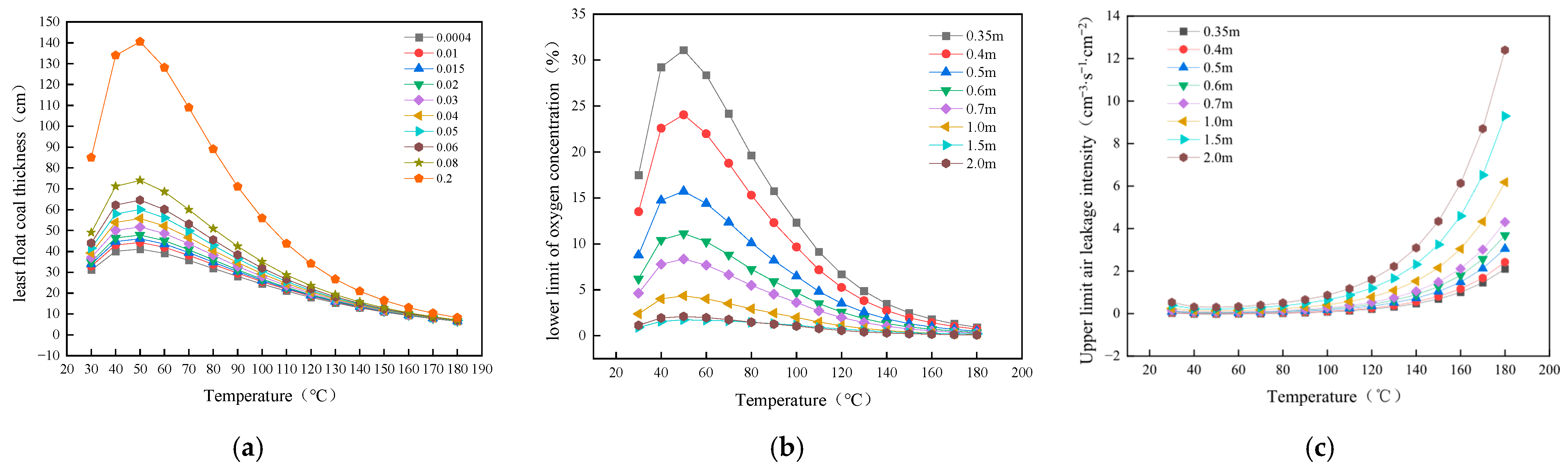
Figure 3a presents the variation law for minimal floating coal thickness obtained through the coal spontaneous combustion experiment at an air leakage intensity of 0~0.2 cm−3·s−1·cm−2. Based on the diagram, at 30–50 °C, the minimal floating coal thickness increases as temperature increases, while at >50 °C, the minimal floating coal thickness decreases as temperature increases.
Figure 3b,c present the lower limit of oxygen concentration and the upper limit of air leakage intensity at a floating coal thickness of 0.35~2 m and a coal temperature of 30 °C~180 °C determined based on experimental results. Clearly, the lower limit of oxygen concentration required for spontaneous combustion for 0.35 m thick floating coal is 31.08%, which is impossible inside loose floating coal, so spontaneous combustion will not occur. At a floating coal thickness of 0.35 m, a coal temperature of 50 °C induces the smallest upper limit of air leakage intensity.
The spontaneous combustion experiment of No.5 coal seam in Chenjiagou Coal Mine was carried out by using XK-8 type coal spontaneous combustion experimental platform (from China Shenmu Chuangyou Company, Shenzhen, China). The experimental test device consisted of an adiabatic oxidation device, a gas supply system, a temperature detection and control system, an oxidation gas product analysis system, and a quality change detection system. The average particle size of the coal sample was 0.86 mm, and the experimental test temperature ranged from room temperature to 190 °C. The spontaneous combustion process of residual coal in goaf was simulated, and the spontaneous combustion period and oxidation characteristic parameters of coal were measured. Based on the experimental test and theoretical analysis of five layers (average particle size of 0.86 mm) of mine coal, the lowest spontaneous combustion duration was 30 days at an underground starting temperature of 23.42 °C, and while a value of 26 days was obtained in our laboratory, with a starting temperature of 30 °C. According to the calculation formula for coal spontaneous combustion limits, the floating coal thickness and coal sample temperature are 0.35 m and 50 °C, respectively, after the calculation of the lower limit of oxygen concentration Cmin = 31.08%. The oxygen concentration of fresh air flow is far less than 31.08%, and thus this does not conform to real site conditions. At this time, floating coal cannot spontaneously combust. At a coal sample temperature of about 50 °C, the upper limit of air leakage intensity has its minimum value, being lower than the air leakage intensity required for floating coal to spontaneously combust. Table 1 displays the upper limit of air leakage intensity at different floating coal thicknesses. At 50 °C, the floating coal has its maximum thickness. When the floating coal thickness is lower than this limit for thickness at this temperature, the floating coal does not combust spontaneously. A higher air leakage intensity leads to more heat being removed via airflow. Table 2 shows the limit for floating coal thickness under diverse air leakage intensities.

3.2. Study on the Oxidation Temperature Rise Zone Range

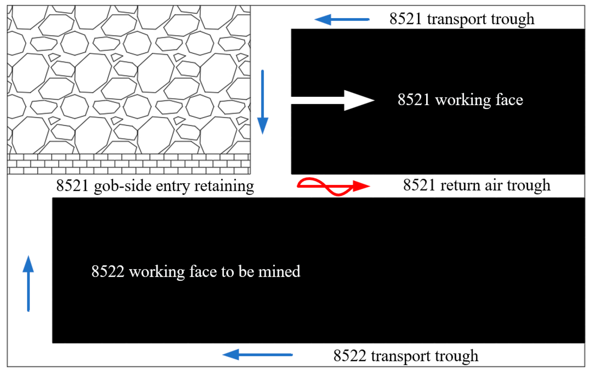
Floating coal thickness and the width of the upper layer 8511 goaf and the lower layer 8521 goaf are calculated. The upper layer 8511 working face is mined out, and there is a certain thickness of residual coal and a 6.5 m thick coal pillar amid the upper layer goaf and two roadways. The thickness of the upper layer 8511 working face is 11.9 m, of which the thickness of the machine cutting is 3 m, while that of the top coal is 8.9 m. The lower layer 8521 working face is being mined, and there are two residual coals with a thickness of 4 m within the goaf inside the fully mechanized caving face. Affected by caving during the mining process, both the upper and lower layered goafs will be connected, forming the composite goaf, thereby increasing floating coal thickness inside this composite goaf. Simultaneously, the residual coal in two roadways of the upper layer and the coal pillar with a width of 6 m also fall into the goaf of the fully mechanized caving face inside the goaf-side entry retaining in lower layer 8521. The thickness of this fully mechanized caving face within the goaf-side entry retaining of the lower layer is 10.5 m, of which the thickness of the machine cutting is 4 m. According to the observed top coal thickness and the recovery rate on the working face, the mean floating coal thickness and width are determined.
(1) The floating coal thickness amid upper layered goaf:
(11.9 − 3) × (1 − 85%)/(1 − 30%) = 1.9 m
(2) The coal and rock mass thickness at lower layered inlet and return air trough and the support at both ends:
(10.5 − 4)/(1 − 30%) = 9.30 m
(3) The floating coal thickness amid lower layered goaf:
(10.5 − 4) × (1 − 85%)/(1 − 30%) = 1.40 m
According to the above formulas, 
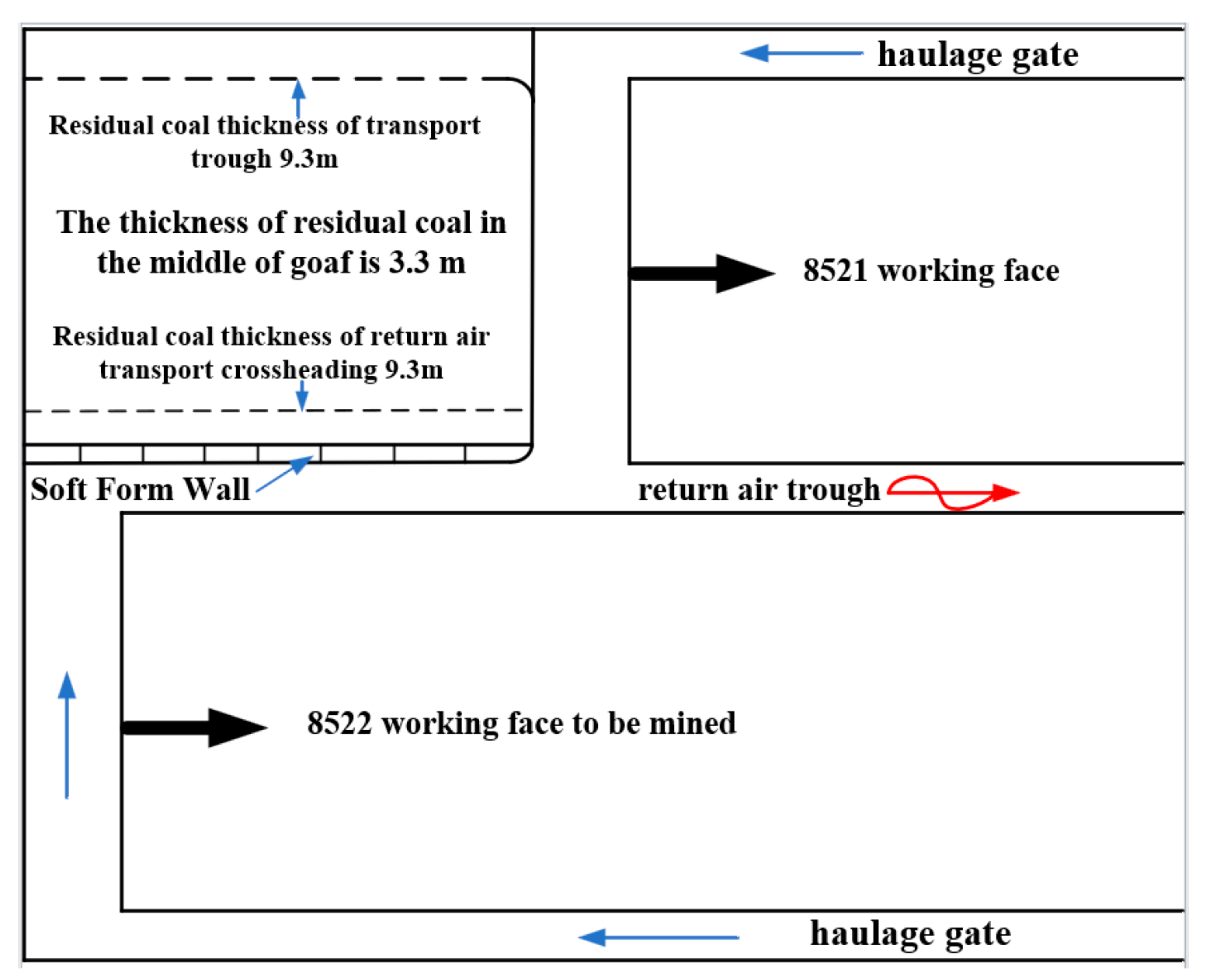
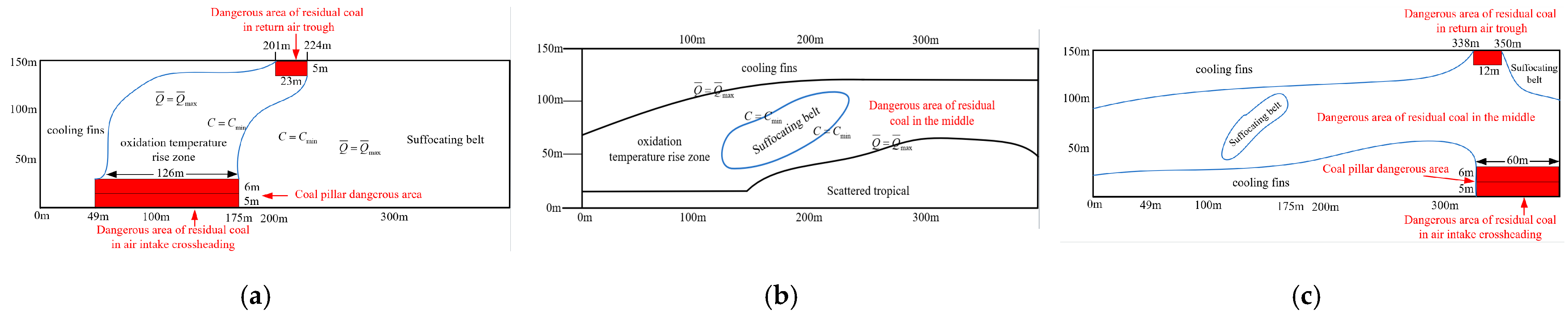
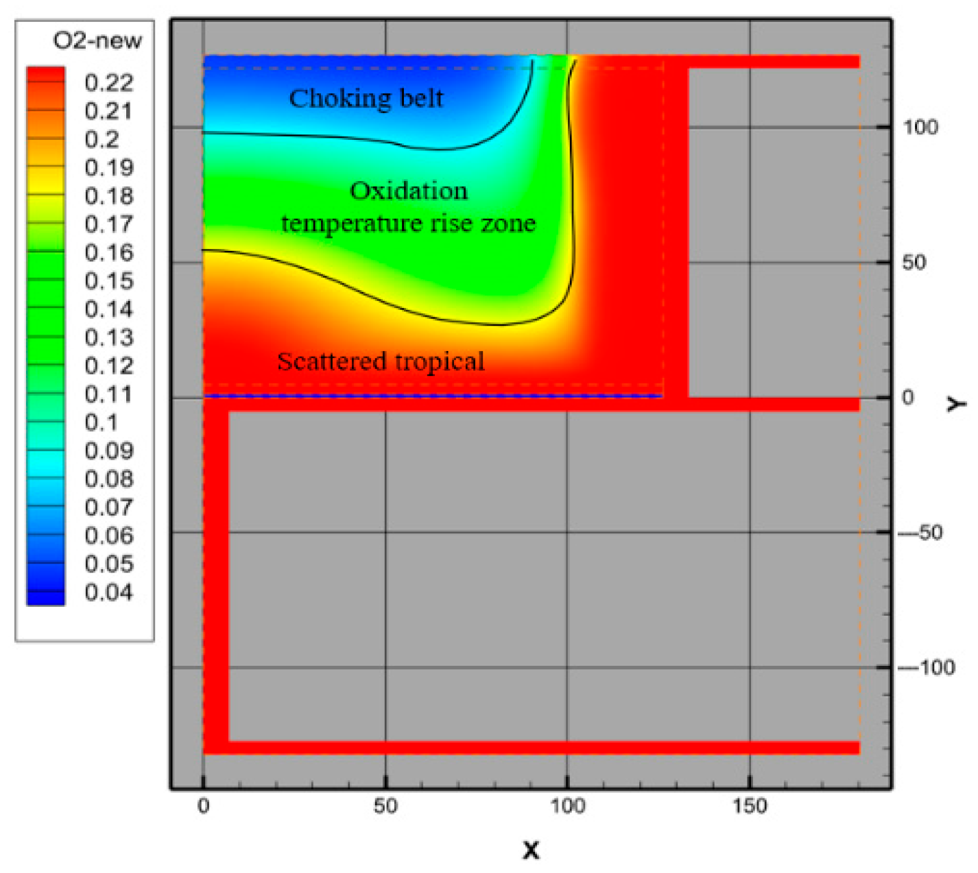
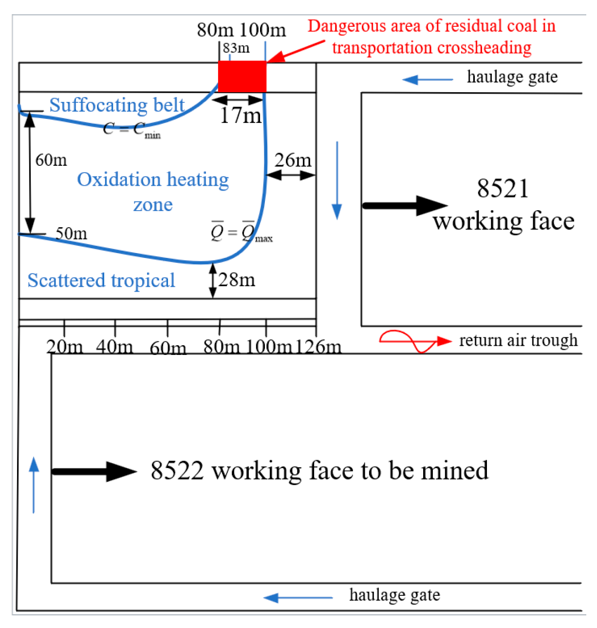
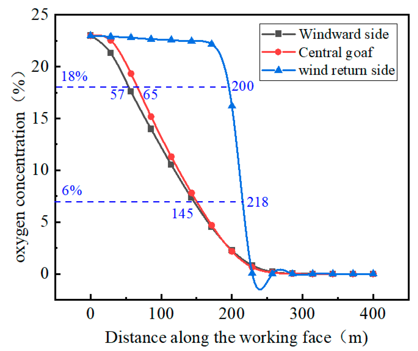
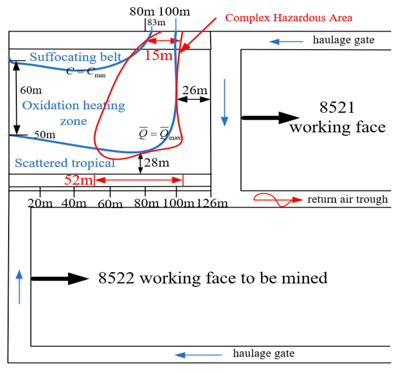
Figure 4 displays the contour map of floating coal thickness in this composite goaf within goaf-side entry retaining in lower layer of Chenjiagou Coal Mine. Based on our experimental data for coal spontaneous combustion, at floating coal thickness of 1.9 m, lower limit oxygen concentration Cmin = 6%, upper limit air leakage intensity is 0.282 cm−3·s−1·cm−2, the corresponding seepage velocity is 11.28 × 10
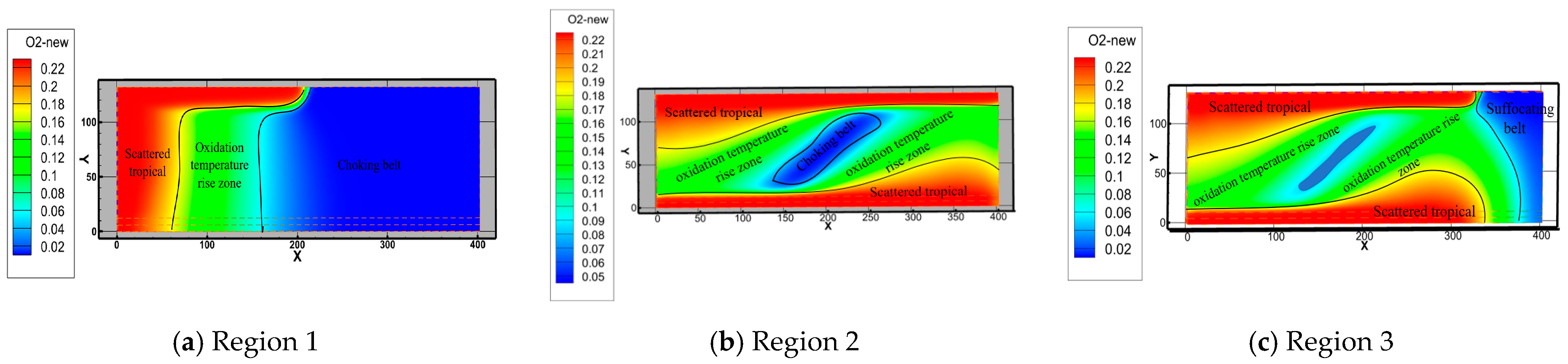
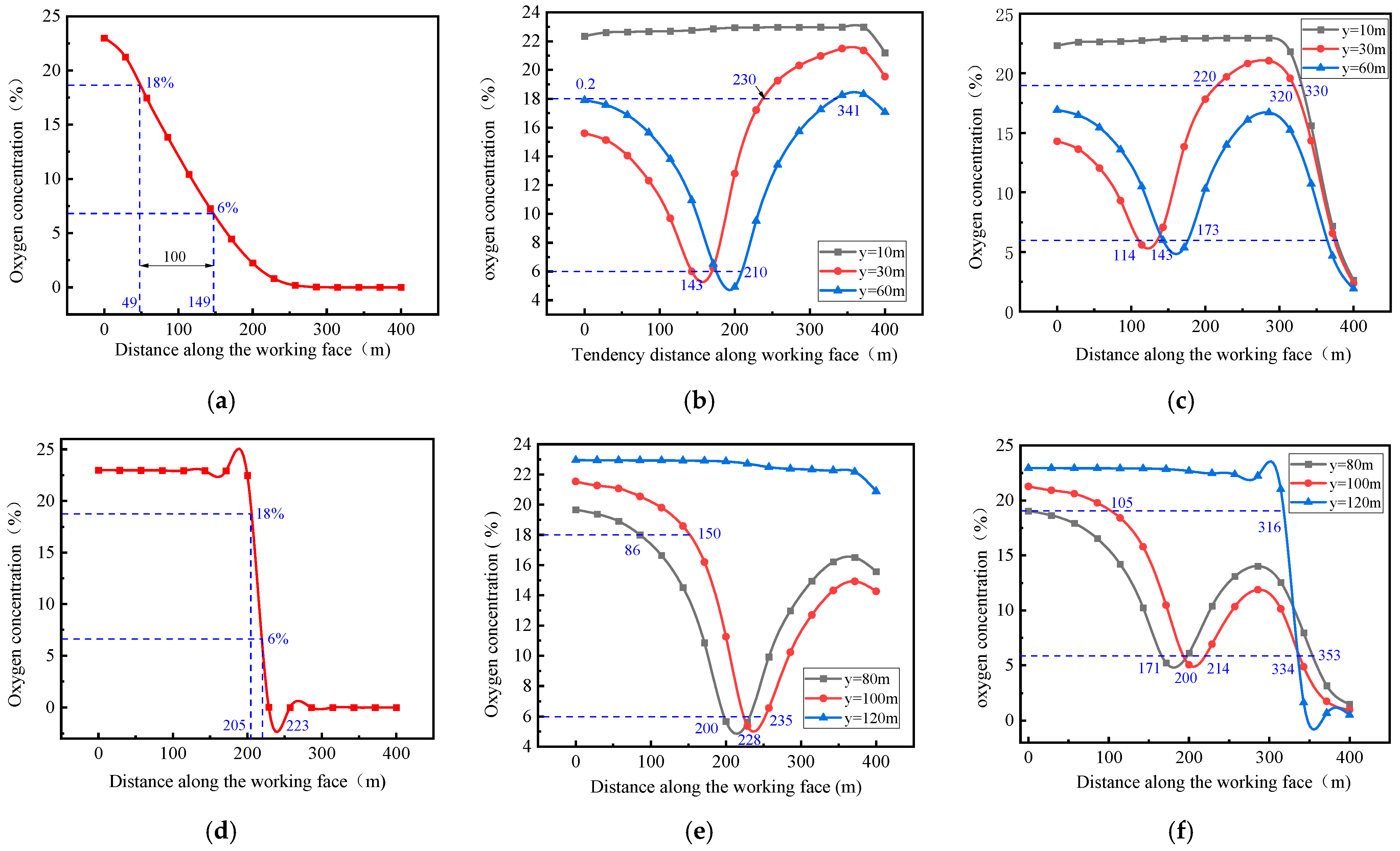
⁻³ m/s, and the oxidation heating zone is ranges from 6% to 18%.

4. Numerical Model Construction

4.1. Mathematical Model Construction

Gas flow obeys the mass conservation law, momentum conservation law, energy conservation law and transport equation of components [20].
s i = j = 1 3 D i j μ v j + j = 1 3 C i j 1 2 ρ v j v j
When goaf is an isotropic porous medium, that is, porosity, viscosity and inertial resistance coefficients at each position are equal in all directions, the momentum loss source term is [21]:
s i = μ α v j + 1 2 C 2 ρ v j v j

4.2. Geometric Model

We establish the working face geometric model based on the real situation on the 8521 working face in Chenjiagou Coal Mine. The model includes the upper layer 8511 goaf and the lower layer 8521 goaf. In this paper, considering the limitations of Fluent large-scale modeling, the upper layer 8511 goaf is divided into three different regions following the dip direction of the lower layer 8521 working face in order to establish a geometric model. The region contains three thin coal seam areas, namely Regions 1–3. Additionally, when the intersection point between the return airway and the goaf boundary is taken as the origin, this working face is in a positive direction relative to the X-axis’, the working face strike is in a positive direction relative to the Y-axis’, and the vertical upward direction of the floor is in a positive direction relative to the Z-axis’, and geometric model of the 8521 working face in the lower layer is established. The geometric model of the upper and lower layers is observed in Figure 5. Geometric dimensions can be obtained from Table 3.

4.3. Boundary Conditions

For the free-flow field, air intake roadway inlet is velocity boundary. Following the real situation in Chenjiagou Coal Mine, cement wall of goaf-side entry retaining section is set as interior (air leakage, void ratio = 0.1), and the ventilation mode is set as ‘W’ type. According to the determined numerical simulation operating parameters, flow field under the goaf under air leakage conditions is numerically simulated. Baseline simulation parameters can be observed in Table 4.

5. Numerical Simulation Results and Analysis

5.1. Distribution Characteristics and Dangerous Area Determination of ‘Three Zones’ in Upper Layered Goaf

Oxygen concentration inside the goaf represents an extremely important basis for determining the dangerous area for spontaneous combustion [22]. ANSYS Fluent simulation software (https://www.ansys.com) [23] was utilized for simulating the oxygen concentration distribution within the upper layered goaf. The distribution of three coal spontaneous combustion zones within the upper layered goaf can be observed in Figure 6.
According to our analysis, the upper oxygen concentration near the intake and return air lanes of working face is higher. The oxygen concentration of zone 1 is mainly concentrated around its open-off cut. There may be cracks within the thin coal seam in the roof area of the roadway, causing this area to have a high level of air leakage, meaning that the oxygen concentration within the area around the open-off cut and amid the goaf is higher. The oxygen concentration within the upper goaf in the inlet and the return air roadway in region 2 is higher. This is because the air leakage channel in region 2 flows into the upper goaf due to the effect of wind pressure, and the oxygen concentration amid upper goaf is low, while that within the thin coal seam of the roadway roof in region 3 is high. Because of wind pressure, air flow inside this area flows into the upper goaf, and the oxygen concentration in the upper goaf of both the inlet and the return air outlet is low, while that on the inlet side is as high as 21% near the inlet corner. As it moves deeper into the goaf, the oxygen concentration decreases. The oxygen diffusion and oxygen consumption of the residual coal inside the goaf are major factors affecting oxygen concentration distribution inside the goaf. Air flow penetrates into the upper layered goaf along the cracks in the thin coal seam within the roof of the intake and return air roadway, which increases the hidden coal spontaneous combustion risk. To further determine the specific location of the three spontaneous combustion zones in the upper layer under the simulated conditions, the monitoring points are set along the strike direction on the air inlet and return roadway sides inside the goaf, and corresponding oxygen concentration variation curves are drawn (Figure 7).
Based on figure analysis, on the air inlet side in the goaf of Region 1, the area 0~49 m away from the working face is viewed as the heat dissipation zone, the area 49~149 m away from the working face is viewed as the oxidation heating zone, and the area 149~400 m away from the working face is viewed as suffocation zone. The oxidation heating zone on the return air side is small, with a length of only 18 m. In addition, the heat dissipation zone within Region 2 is concentrated near the two lanes and is 400 m long. As the working face advances, the oxygen concentration of the intake and return air sides within the goaf decreases first and then increases along the working face. In addition, the inlet side has a maximal length of 173 m, while that on the return side is 314 m. The suffocation zone is located in a small area amid the goaf. The oxidation heating zone has a maximal length of 195 m on the inlet side of Region 3, while that on the return air side is 171 m. The suffocation zone is located deep in the goaf, and its maximal length is 66 m. Based on the oxidation heating zone distribution features, dangerous areas for coal spontaneous combustion in the three areas are characterized by an oxygen concentration of 6%~18% on the air inlet and return roadway sides inside the goaf, as shown in Figure 8. The location and distribution of these areas are shown in Table 5.

5.2. Distribution Characteristics and Dangerous Area Determination of ‘Three Zones’ in Lower Layered Goaf

According to the lower limit of oxygen concentration associated with different floating coal thicknesses, the floating coal thickness of the composite goaf, and the oxygen concentration obtained by means of simulation, the distribution of the ‘three zones’ distribution in the lower layer goaf 8521 goaf-side entry retaining working face can be seen in Figure 9. The upper layered goaf’s dangerous area is plotted in Figure 10.
As observed, the area 0 m~21 m away from the working face inside the goaf on the air inlet side belongs to the heat dissipation zone, the area 21 m~38 m away from the working face inside the goaf on the air inlet side is in the oxidation heating zone, and the area with an oxygen concentration decreasing to 6% after 38 m is in the asphyxiation zone. Considering the air leakage channels on the flexible formwork wall of the goaf side of the air intake crossheading, the oxygen concentration deep inside the goaf near the goaf side is too high. The oxygen volume fraction within the area 27 m~38 m away from the working face on the return air side is between 6% and 18%, representing a dangerous area regarding residual coal in the transport crossheading. The deep part of the goaf is 49 m~90 m away from the flexible formwork wall along the strike direction, representing the dangerous area regarding residual coal in the middle.

5.3. Coal Spontaneous Combustion Danger Zone Distribution Inside Composite Goaf

In the mining of a fully mechanized caving face inside a goaf-side entry retaining on the lower layer, the goaf interacts with the upper layer goaf, forming the composite goaf, which causes the upper layer residual coal and the 6 m wide coal pillar to fall into the lower layer goaf, with the floating coal thickness increasing. Considering the influence induced by air leakages, residual coal within the composite goaf is likely to spontaneously combust. Therefore, according to the limit parameters for coal spontaneous combustion and the oxygen mass fraction, three-zone coal spontaneous combustion inside the goaf is identified. Changes in the oxygen mass fraction in the upper layer goaf and the lower layer goaf-side entry retaining goaf can be observed in Figure 11 and Figure 12, respectively.
According to the analysis, an oxygen concentration of 6~18% is observed in the range of 51 m~149 m along working face, while that within 60 m~152 m along the middle of the goaf is 6~18%, and that within 190 m~220 m along the return air side is 6~18%. An oxygen concentration of 6~18% is observed in the 88 m~103 m range along the inclination of working face, while a concentration of 12~18% is observed in the range of 0 m~101 m along the inclination amid the goaf, while that within the 0 m~126 m range along the inclination of the return air side is 22%. Three spontaneous combustion zones inside the composite goaf due to the overlapping of the coal spontaneous combustion danger zones inside the upper layered goaf and the coal spontaneous combustion danger zone inside the composite goaf in the lower layered goaf-side entry retaining fully mechanized caving face can be seen in Table 6, while the composite danger zone can be observed in Figure 13.
In summary, the dangerous areas regarding coal spontaneous combustion inside the composite goaf on the lower layer goaf-side entry retaining are as follows: in the air inlet channel, the 23~38 m area on the air inlet side as well as the narrow 0~121 m area along the flexible formwork wall in the strike direction, and in the central part, the middle area 23 m~38 m from the goaf on the inlet side to the working face and the middle area 23 m~75 m from goaf of the return side to the working face. In comparison with previous research results, compared with the single coal seam condition, the distribution of dangerous areas in the composite goaf is larger and the positions are more dispersed [24,25]. This may be because the lower layer mining leads to the collapse of the upper layer coal, which increases the thickness of the floating coal in the goaf, and the existence of the three-dimensional air leakage channels increases the range of oxygen diffusion. In view of the different distribution characteristics of natural dangerous areas of coal in the composite goaf, the measures for preventing and controlling coal spontaneous combustion are also different. In the actual mining process, the natural prevention and control of coal spontaneous combustion can be carried out by means of partition dynamic prevention and control. The 23~38 m area on the air inlet side is the key prevention and control area, and a pulsed nitrogen injection nozzle should be added to the tail beam of the hydraulic support. The 23~75 m area on the return air side is a dynamic inerting area, which can be continuously inerted by the nitrogen generator. The flexible formwork wall area is a plugging monitoring area, which can be filled with a polymer spray plugging material.

6. Conclusions

(1)
The key conditions of coal spontaneous combustion danger zones are determined according to the coupling relationship between floating coal thickness, the lower limit of oxygen concentration, and leakage intensity. Typically, the lower limit of oxygen concentration required for coal to spontaneously combust significantly declines with increasing floating coal thickness. The ultimate air leakage intensity of goafs is 0.282 cm−3·s−1·cm−2. When the intensity is less than this value, it will promote an oxidation reaction; otherwise, it will suppress coal spontaneous combustion.
(2)
The coal spontaneous combustion danger zone distribution features inside composite goaf are easily affected by the floating coal thickness, oxygen concentration, and leakage intensity. From these critical conditions, it is determined that the danger zone is concentrated at 23~38 m from working face of intake side, 23~75 m amid the goaf of return side, and 0~121 m near the flexible formwork wall.
(3)
For the thick coal seam composite goaf, based on the partition dynamic prevention and control strategy, the top coal caving process and the recovery rate should be optimized to control the thickness of the floating coal in the goaf. A polymer spray plugging material should be used to reduce the air leakage intensity of the gob-side entry retaining, and the oxygen concentration in the goaf should be dynamically controlled in combination with the inerting process, so as to realize the efficient prevention and control of coal spontaneous combustion in the goaf under the condition of layered mining.
(4)
In this study, the numerical simulation of dangerous areas in the layered mining of static gob-side entry retaining is carried out for the composite goaf of gob-side entry retaining. The research results are suitable for mining areas with similar geological conditions. Subsequently, risk assessments of gas and coal spontaneous combustion coupling disasters under dynamic mining conditions can be constructed.

Author Contributions

Conceptualization, Supervision, Formal analysis, N.Y.; Writing (original draft), L.W.; Formal analysis, J.G.; Methodology, Investigation, Y.L.; Methodology, Investigation, C.C.; Supervision, Formal analysis, B.G. All authors have read and agreed to the published version of the manuscript.

Funding

The research was supported by the Key R&D Project in Shaanxi Province (grant number 2025SFYBXM549 and 2025SFYBXM557), Xianyang Key Research and Development Program (grant numbers L2024-ZDYF-ZDYF-SF-0050) and the National Natural Science Foundation of China (grant numbers 52004209 and 52174198).

Institutional Review Board Statement

Not applicable.

Informed Consent Statement

Not applicable.

Data Availability Statement

The data presented in this study are available on request from the corresponding author.

Acknowledgments

We are grateful for the support of laboratories and assistants who provided experimental conditions for this work.

Conflicts of Interest

All authors declare that the research was conducted in the absence of any commercial or financial relationships that could be construed as a potential conflict of interest.

Nomenclature

hFloating coal thickness (m)
ρgAir flow density of working face (g·cm−3)
cgSpecific heat capacity (J·g−1·°C−1)
q0(T)Exothermic intensity of experimental coal sample (J·cm−3·s−1)
λcThermal conductivity of residual coal (J·cm−1·°C−1·s−1)
U Air leakage velocity in goaf (cm·s−1)
TmMaximum temperature of floating coal (°C)
nPorosity
T ¯ m Average temperature of floating coal (°C)
TyRock stratum temperature (°C)
QUltimate air leakage intensity (J·kg−1)
xEmpirical coefficient
SiMomentum loss source term (N·s/m)
DijViscosity loss coefficient
μDynamic viscosity of porous media in goaf (Pa·s)
vjThe velocity component in the j direction (m·s−1)
CijInertia loss coefficient
ρGas density(kg·m−3)
αPermeability of porous media
C2Internal resistance factor
C O 2 0 Initial oxygen concentration (%)
Cminlimit oxygen concentration (%)

References

  1. Cheng, Z.Z. Present situation and prospect of coal washing and processing in China under the new situation. Coal Process. Compr. Util. 2022, 1, 20–26. [Google Scholar]
  2. Wang, C.P.; Du, Y.X.; Deng, Y.; Zhang, Y.; Deng, J.; Zhao, X.Y.; Duan, X.D. Study on Spontaneous Combustion Characteristics and Early Warning of Coal in a Deep Mine. Fire 2023, 6, 396. [Google Scholar] [CrossRef]
  3. Hu, L.T.; Zhu, H.Q.; Wang, J.S.; Qu, B.L.; Liao, Q.; Tao, R.Y.; Zhang, Z.Q. Research and application of continuous and precise nitrogen injection fire extinguishing technology in coal mines. Miner. Eng. 2024, 215, 108801. [Google Scholar] [CrossRef]
  4. Zhang, J.G.; Wang, W.; Li, Y.H.; Li, H.M.; Zhang, G.J.; Wu, Y.H. Fracture Distribution Characteristics in Goaf and Prevention and Control of Spontaneous Combustion of Remained Coal under the Influence of Goaf-Side Entry Retaining Roadway. Energies 2022, 15, 4778. [Google Scholar] [CrossRef]
  5. Guo, J.; Chen, C.M.; Wen, H.; Cai, G.B.; Liu, Y. Prediction model of goaf coal temperature based on PSO-GRU deep neural network. Case Stud. Therm. Eng. 2024, 53, 103813. [Google Scholar] [CrossRef]
  6. Hu, D.J.; Li, Z.X. Dynamic distribution and prevention of spontaneous combustion of coal in goaf-side entry retaining goaf. PLoS ONE 2022, 17, e0267631. [Google Scholar] [CrossRef]
  7. Chen, X.K.; Song, C.; Zhang, Z.P. The Influence of the Fire Point on the Thermal Dynamic Disaster in the Goaf. Fire 2024, 7, 270. [Google Scholar] [CrossRef]
  8. Guo, J.; Wang, L.; Liu, Y.; Chen, C.M.; Cai, G.B.; Du, W.T. Experimental Study on the Influence of Staged Oxygen Consumption on the Oxidation Characteristics of Coal Spontaneous Combustion. Fire 2024, 7, 359. [Google Scholar] [CrossRef]
  9. Xu, J.C.; Zhang, X.H.; Deng, J.; Wen, H.; Wang, Z.B.; Jin, Y.F. Study on “Three Zones” Law and Spontaneous Combustion Risk in Goaf of 2106 fully-mechanized Caving Face in Changcun Coal Mine. J. Hunan Univ. Sci. Technol. (Nat. Sci. Ed.) 2004, 19, 1–4. [Google Scholar]
  10. Xu, Y.H.; Cheng, X.J.; Wen, H.; Zhai, X.W.; Fan, S.X.; Jin, Y.F.; Liu, Y.; Yu, Z.J. Research on spontaneous combustion law and precise prevention and control technology of extra-thick residual coal in multi-layer staggered mining. Coal Sci. Technol. 2024, 52, 101–113. [Google Scholar]
  11. Ma, L.; Zhang, P.Y.; Chen, X.K.; He, Y.P.; Wei, G.M.; Fan, J. Numerical Investigation of coupling hazard zone of coal spontaneous combustion and gas in goaf for high-gas mines. Case Stud. Therm. Eng. 2024, 63, 105341. [Google Scholar] [CrossRef]
  12. Li, C.M.; Li, Y.Y.; Wang, H.W. Study on the distribution law of spontaneous combustion danger area in fully-mechanized caving face of extra-thick coal seam. Coal Mine Saf. 2013, 44, 34–37. [Google Scholar]
  13. Wang, Z.J.; Zhang, D.P.; Han, W. Measurement and numerical simulation of spontaneous combustion dangerous area in fully-mechanized caving goaf of Liujia Coal Mine. Mod. Min. 2023, 39, 187–190. [Google Scholar]
  14. Liu, S.; Lu, S.D.; Wang, K.; Wang, Z.; Bai, G.X. Study on the dangerous area of coal spontaneous combustion in the goaf of fully-mechanized caving face with large dip angle in Wangjiashan Coal Mine. Energy Environ. Prot. 2023, 45, 62–67. [Google Scholar]
  15. Hao, M.; Li, Y.L.; Song, X.L.; Kang, J.H.; Su, H.T.; Zhou, F.B. Hazardous areas determination of coal spontaneous combustion in shallow-buried goafs of coal seam group: A physical simulation experimental study. Environ. Earth Sci. 2019, 78, 1–11. [Google Scholar] [CrossRef]
  16. Zhang, F.J.; Xu, H.; Qin, Y.P.; Guo, M.Y.; He, S.D. Numerical simulation and investigation of methane gas distribution and extraction in goaf with U-type ventilation of working face. Environ. Sci. Pollut. Res. 2023, 30, 59510–59527. [Google Scholar] [CrossRef]
  17. He, L.; Wu, D.; Ma, L.F. Numerical simulation and verification of goaf morphology evolution and surface subsidence in a mine. Eng. Fail. Anal. 2023, 144, 106918. [Google Scholar] [CrossRef]
  18. Zhang, Y.F.; Cui, C.B.; Peng, R.; Li, W. Study on the law of air leakage in goaf under the influence of double-series coal seam mining. Heliyon 2025, 11, 41337. [Google Scholar] [CrossRef]
  19. Chen, X.J.; Du, Y.F.; Wang, L.; Zhao, S. Evolution and application of airflow permeability characteristics of goaf in roof cutting and pressure releasing mining method. Energy Sci. Eng. 2020, 8, 2073–2085. [Google Scholar] [CrossRef]
  20. Gui, X.H.; Xue, H.T.; Zhan, X.R.; Hu, Z.Y.; Song, X.G. Measurement and Numerical Simulation of Coal Spontaneous Combustion in Goaf under Y-type Ventilation Mode. ACS Omega 2022, 7, 9406–9421. [Google Scholar] [CrossRef]
  21. Zheng, Y.N.; Li, S.S.; Xue, S.; Jiang, B.Y.; Ren, B.; Zhao, Y. Study on the evolution characteristics of coal spontaneous combustion and gas coupling disaster region in goaf. Fuel 2023, 349, 128505. [Google Scholar] [CrossRef]
  22. Zhang, X.Q.; Zou, J.X. Research on collaborative control technology of coal spontaneous combustion and gas coupling disaster in goaf based on dynamic isolation. Fuel 2022, 321, 124123. [Google Scholar] [CrossRef]
  23. Wang, J.W.; Liu, X.F. CFD Simulation Study on Nitrogen Injection to Suppress Coal Spontaneous Combustion in Goaf under Downward-Ventilation Conditions. ACS Omega 2025, 10, 27165–27173. [Google Scholar] [CrossRef]
  24. Gao, S.Q.; Tang, M.Y.; Luo, X.; Zhou, L.; Qiu, J.W.; Zhang, R.Q. Dynamic simulation study on space-time evolution law of coal spontaneous combustion hazardous zone and high-temperature points in goaf. Int. J. Heat Mass Transf. 2025, 251, 127321. [Google Scholar] [CrossRef]
  25. Gao, S.A.; Gao, D.Y.; Liu, Y.L.; Chai, J.; Chen, J.H. Distribution Law of Coal Spontaneous Combustion Hazard Area in Composite Goaf of Shallow Buried Close Distance Coal Seam Group. Combust. Sci. Technol. 2023, 195, 1960–1980. [Google Scholar] [CrossRef]
Figure 1. Schematic diagram for 8521 working face layout.
Fire 08 00298 g001
Figure 2. Ventilation system diagram of 8521 working face.
Fire 08 00298 g002
Figure 3. Curve of limiting characteristic parameters with coal temperature under different conditions: (a) The variation in minimal floating coal thickness according to coal temperature, (b) Change in lower limit oxygen concentration depending on coal temperature, (c) Variation in upper limit air leakage intensity depending on coal temperature.
Fire 08 00298 g003
Figure 4. Plane diagram of floating coal thickness in goaf.
Fire 08 00298 g004
Figure 5. Geometric model of upper and lower layers: (a) Upper-stratified region 1, (b) Upper-stratified region 2, (c) Upper-stratified region 3, (d) Lower layered goaf.
Fire 08 00298 g005
Figure 6. Layered oxygen concentration distribution: (ac) Regions 1–3.
Fire 08 00298 g006
Figure 7. Variation curve for oxygen concentration on both inlet and return air sides in goafs in Regions 1, 2 and 3: (a) Region 1 inlet side oxygen concentration curve, (b) Region 2 inlet side oxygen concentration curve, (c) Region 3 inlet side oxygen concentration curve, (d) Region 1 return air side oxygen concentration curve, (e) Region 2 return air side oxygen concentration curve, (f) Region 3 return air side oxygen concentration curve.
Fire 08 00298 g007
Figure 8. Dangerous areas for coal spontaneous combustion inside the upper layer goaf: (a) Region 1’s dangerous area plan; (b) Region 2’s dangerous area plan; (c) Region 3’s dangerous area plan.
Fire 08 00298 g008
Figure 9. Distribution cloud diagram of the ‘three zones’ inside the goaf on the fully mechanized caving face of the layered goaf-side entry retaining.
Fire 08 00298 g009
Figure 10. Plane diagram of the dangerous area of layered residual coal.
Fire 08 00298 g010
Figure 11. Variation curve for oxygen concentration in upper layered goaf.
Fire 08 00298 g011
Figure 12. The change curve for oxygen concentration inside goaf of layered goaf-side entry retaining.
Fire 08 00298 g012
Figure 13. Danger zone distribution regarding coal spontaneous combustion inside the composite goaf.
Fire 08 00298 g013
Table 1. Lower limit oxygen concentration and upper limit air leakage intensity at different floating coal thicknesses.
Floating coal thickness/m0.350.400.50.60.71.01.52.033.3
Lower limit of oxygen concentration/%31.0824.0515.7211.148.354.342.111.290.660.57
Upper limit air leakage intensity/cm−3·s−1·cm−2−0.020−0.0030.0250.0500.0720.1290.2160.2980.4580.51
Table 2. Ultimate floating coal thickness at diverse air leakage intensities.
Air leak intensity/cm−3·s−1·cm−20.00040.010.0150.020.030.040.050.060.080.2
The limit thickness of floating coal/cm41.0844.2946.0647.8851.7255.7860.0765.5674.08140.54
Table 3. Geometric parameter table.
Regional ModelGeometric Size (m)Regional ModelGeometric Size (m)
Upper-stratified region 1325 × 5 × 1Lower layer 8521 mined-out area126 × 122 × 4
Upper-stratified region 2780 × 5 × 18521 working face122 × 7 × 4
Upper-stratified region 3620 × 5 × 18521 goaf-side entry retaining240 × 5 × 4
Table 4. Baseline simulation parameters.
TitleNumerical ValueTitleNumerical Value
Air velocity in air intake gateway (m/s)1.5Section area of air intake roadway (m2)20
Turbulence intensity (%)3.23Air distribution volume of working face (m3/s)30
Goaf porosity (%)0.2Thin coal seam thickness in 8521 fully-mechanized caving face1 m
Table 5. Dangerous areas for coal spontaneous combustion inside the layered goaf.
Regional LocationDistribution Range (m)Region Area (m2)
Area 1 dangerous area on the windward sideLength 126, width 114016
Area 1 dangerous area on return air sideLength 12, width 15180
Area 2 dangerous area in the middle of goafLength 400, width 6027,729
Area 3 dangerous area on the windward sideLength 60, width 11660
Area 3 dangerous area on return air sideLength 12, width 15180
Area 3 dangerous area amid the goafLength 380, width 5229,462
Table 6. Three-zone spontaneous combustion width inside goaf.
MethodPositionScattered Tropical (m)Oxidation Zone (m)Asphyxiation Band (m)
Numerical SimulationWindward side>103 m88 m~103 m<88 m
Wind return side0~126 m//
Disclaimer/Publisher’s Note: The statements, opinions and data contained in all publications are solely those of the individual author(s) and contributor(s) and not of MDPI and/or the editor(s). MDPI and/or the editor(s) disclaim responsibility for any injury to people or property resulting from any ideas, methods, instructions or products referred to in the content.

