Article

Experimental Investigation of Flame Spread Characteristics in Cable Fires Within Covered Trays Under Different Tilt Angles

by
Changkun Chen
1,*,
Yipeng Bao
1,
Boyuan Zuo
1,
Jia Zhang
2 and
Yuhuai Wang
2
1
Institute of Disaster Prevention Science and Safety Technology, Central South University, Changsha 410018, China
2
State Grid Jiangsu Elect Power Co., Ltd., Nanjing Power Supply Co., Nanjing 210009, China
*
Author to whom correspondence should be addressed.
Fire 2025, 8(7), 272; https://doi.org/10.3390/fire8070272
Submission received: 4 June 2025 / Revised: 6 July 2025 / Accepted: 9 July 2025 / Published: 11 July 2025
(This article belongs to the Special Issue Fire Detection and Public Safety, 2nd Edition)

Abstract

In the actual installation of cables, inclined cable laying within covered cable trays is a relatively common method. To investigate the effects of different tilt angles on the combustion behavior of cables within covered cable trays, aluminum conductor polyethylene-insulated power cables were used as the test cables. The flame morphology, temperature distribution, and fire spread rate during the cable combustion process were analyzed for experimental scenarios for which the cable laying angles and the ignition positions changed. The results indicate that the inclination angle of the covered cable tray has a significant impact on flame propagation and temperature distribution. For the ignition located at the lowest part of the cable, the fire spread rate increases significantly with the tilt angle. In contrast, for the ignition located at the highest part of the cable, the fire spread rate initially decreases slightly and then increases, with a relatively smaller overall change in magnitude. Under both ignition positions, the flame spread rate significantly increases at 15–30°. Therefore, in actual cable installation processes, cables within covered troughs should avoid large-angle inclinations.

1. Introduction

With the progress of the times and advancements in technology, electrical power has become increasingly critical to society. The extensive use of electrical equipment has driven a significant increase in cable installations. Meanwhile, the inherent structure and operating environments of cables can pose fire hazards. The main internal ignition risks for cables include sheath aging, conductor overheating due to overloading, and combustion; in humid environments, damage to the outer sheath can cause flashover and ignition [1,2,3,4]. These situations directly threaten people’s lives and property. On 7 May 2023, in Linquan Town, Linyi County, Luliang City, Shanxi Province, a cable fire was ignited by an arc discharge that burned the cable sheath. The fire spread rapidly, resulting in five deaths, a fire-affected area of approximately 100 square meters, and direct economic losses of 8.4042 million yuan.
In actual cable installation practice, cables are generally not directly suspended. Instead, they are supported and installed using various types of cable tray structures. Among these, cable installation within covered cable trays is a relatively common method. Therefore, investigating the combustion performance and fire spread characteristics of polyethylene-insulated cables in covered cable trays has significant practical importance [5,6]. Currently, both domestic and international research on cable fires is extensive, primarily focusing on the thermal decomposition and melting of cable sheathing materials (polymers) during combustion, as well as the fire and smoke spread patterns.
In the study of thermal decomposition of cable sheathing materials during combustion, Zhang et al. investigated the dripping phenomena of commonly used cable sheathing materials such as PE (polyethylene) and PP (polypropylene) during vertical upward combustion, focusing on analyzing the time of first drip appearance and the mass change of drips, and establishing mathematical models to analyze the impact of molten material on polymer mass loss rate [7,8]. Xie et al. conducted experiments to simulate the melting and dripping of polyethylene, a cable insulation material, with a focus on analyzing the heat release rate and CO concentration during combustion, clarifying the coexistence of multiple states (melting, dripping, and flowing) of the polyethylene material during combustion [9,10]. Kandola et al. focused on analyzing the dripping phenomena of thermoplastic materials under different external radiation conditions, investigated the heating and melting process of thermoplastic materials and their dripping process, and established a temperature rise model for the cable surface based on experiments [11,12]. Leung et al. focused on the influence of heat conduction of metal conductors during the thermal decomposition of the outer insulation material of wires, analyzing the mass loss process and temperature distribution of copper core–PE material wires under the heating condition of conductor heat conduction through numerical calculation models [13].
In the research on fire and smoke spread patterns during cable combustion, Liu et al. conducted experimental studies on the combustion characteristics of cables in urban utility tunnels, finding that the combustion process can generally be divided into six stages: ignition, sheath combustion, slow propagation, rapid propagation, fully developed fire, and decay, and analyzed the relationships between ignition time (TTI), mass loss rate (MLR), and heat release rate (HRR) [14]. Huang investigated the combustion characteristics of vertically arranged cables in open and closed environments. The study found that a room with a vertical cable fire can be divided into three zones based on thermal characteristics, and an expression for predicting the ceiling jet temperature was established by fitting experimental data [15]. Chen et al. conducted multilayer cable fire experiments and found that as the number of cable layers increased, flame height and HRR significantly increased, proposing a heat drip-driven propagation mechanism [16]. Wang et al. studied the heat release rate of horizontal cable trays in long and narrow confined spaces, finding that when the cable spacing is one to two times the cable diameter, the peak HRR is maximized, and a predictive model for heat release efficiency in confined spaces was established [17]. Zavaleta et al. studied the burning behavior of cables in a combination of horizontal and inclined configurations. The results showed that compared with the horizontal configuration alone, the combination of horizontal and inclined cables increased the fire growth rate and the heat release rate [18]. Verma, N. et al. proposed a computational fluid dynamics (CFD) method for simulating horizontal cable fires based on the FLASHCAT model and the surface temperature ignition model of the FDS (6.7.7 version) [19]. Zavaleta used Video Fire Analysis (VFA) to investigate flame spread and assess the heat release rate of horizontal cable trays [20]. From the aforementioned studies, it is evident that the existing research on cable combustion mainly focuses on the combustion behavior of different cable arrangements, with primary emphasis on individual angles such as horizontal and vertical, while research on the effects of different inclinations is relatively scarce.
Building on the research of predecessors, we conducted combustion experiments on cables laid within covered cable trays. In practical cable installation, differences in elevation necessitate the use of inclined cable laying in some sections, which poses new challenges for fire prevention. Moreover, in actual fires, flame spread occurs in both upward and downward directions. Therefore, this study establishes conditions for upward and downward flame spread by using two different ignition positions. Based on this, the research investigates the temperature changes and flame images of cables during combustion at different laying angles within covered cable trays. It explores the fire spread characteristics of cables under these two ignition positions and various laying angles. The aim is to provide support for the actual fire safety engineering of cables laid within covered cable trays.

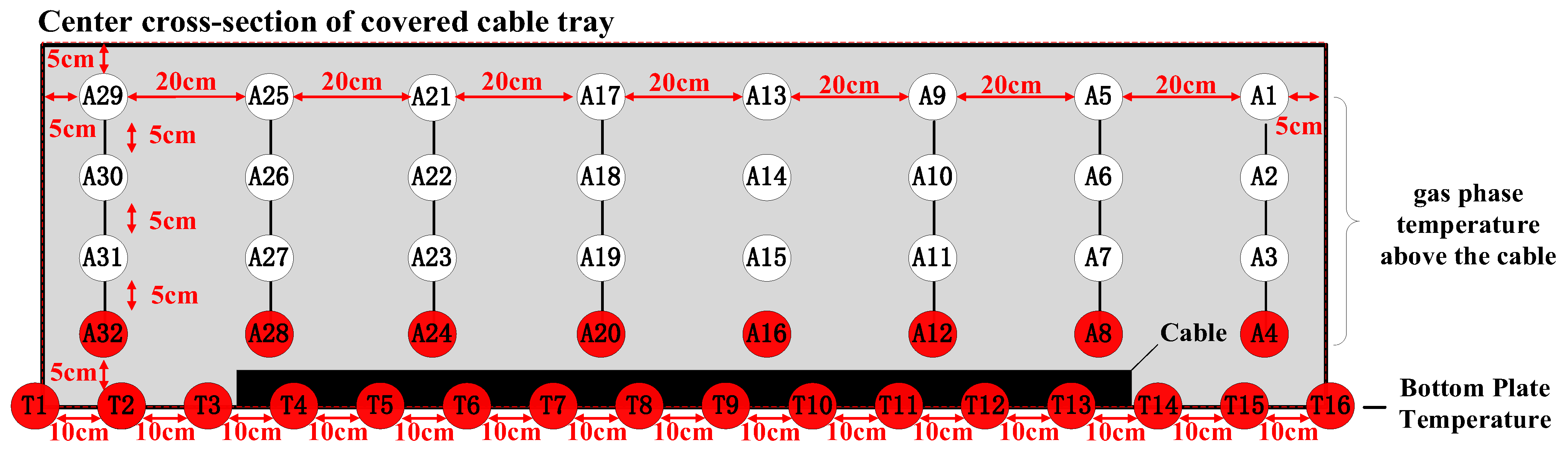
2. Experimental Set-Up

This experiment focuses on the actual conditions of cable installation projects. According to Article 5.6.7 of GB 50217-2018—Standard for Design of Cables of Electric Power Engineering [21], in practice, cables should be laid obliquely in cable tunnels with height differences to avoid step-type laying. At the same time, the experiment focuses on covered trays and uses a commonly available aluminum-core cross-linked polyethylene-insulated power cable as the experimental material. The experimental setup for the covered cable tray is illustrated in Figure 1.
The main structure of the experimental setup was a covered cable tray, which was designed based on the actual covered cable trays used in engineering applications and reproduced at full scale. The experimental setup was open at the two extremities. Three sides of the tray were made of metal materials commonly used in engineering, while one side was made of cesium–potassium fire-resistant glass to facilitate the collection of flame image data during combustion. The cross-sectional dimensions of the tray were 40 × 25 cm (internal space dimensions), and the length of the cable tray was 150 cm. The cables were arranged in a single row and closely packed within the tray, with a total of four cables used. The cable used in this experiment was an aluminum-core cross-linked polyethylene-insulated power cable, model number YJLY 3 × 25. It was a cross-linked polyethylene (XLPE)-insulated, polyethylene-sheathed power cable, with a rated voltage of 0.6/1 kV. The core material of the cable was aluminum, with a wire core diameter of 25 mm. The thickness of the sheath layer was 1.8 mm. These cables were straightened using a tensioning clamp and then laid flat in the cable tray. This experimental scenario considered different tilt angles and ignition positions. The varying tilt angles simulated non-horizontal cable tray installations in real applications, while different ignition positions could affect the combustion behavior. Two ignition positions were designed in this experiment: top-end ignition and bottom-end ignition. In this experiment, a flame torch was used for ignition. Due to the influence of different ignition positions and tilt angles, the time required to ignite the cable varied. Therefore, the ignition time was determined based on the appearance of the flame on the cable. The specific experimental conditions are detailed in Table 1.
The experiment utilized Type K thermocouples. Several thermocouple holes were drilled on the side panel of the covered cable tray for the installation of fixed thermocouples. The arrangement of the thermocouples is detailed in Figure 2. When the tilt angle of the cable tray was adjusted, the corresponding thermocouple measurement points also followed the tilt.

3. Results and Discussion

3.1. Influence of Upstream and Downstream Fire Spread in Covered Cable Trays at Different Tilt Angles

Figure 3 shows the typical flame shapes at different moments under various tilt angles in the covered cable tray. It can be observed from the figure that in the horizontal laying state, cable combustion was relatively stable. This indicated that when cables burned in a horizontal state, the material properties of the cables were relatively stable, and the disturbances caused by differences in material properties were minimal. As the tilt angle increased, under the condition of top-end ignition, the flame gradually exhibited overall combustion, but the degree of combustion weakened. This was because under top-end ignition conditions, the increase in tilt angle led to a continuous reduction in the preheating effect of the flame. Fire spread increasingly relied on the flow of molten material, and the accumulation of this flow further led to overall combustion. Under the condition of bottom-end ignition, the flame clearly exhibited overall combustion, and at a tilt angle of 60°, jet-like combustion occurred. The degree of combustion became more intense. This was because under bottom-end ignition conditions, the preheating effect of the flame front continuously strengthened, and the scale of the flame grew sharply. Meanwhile, the accelerated flow of molten material prolonged the overall combustion time, making the overall combustion more pronounced.

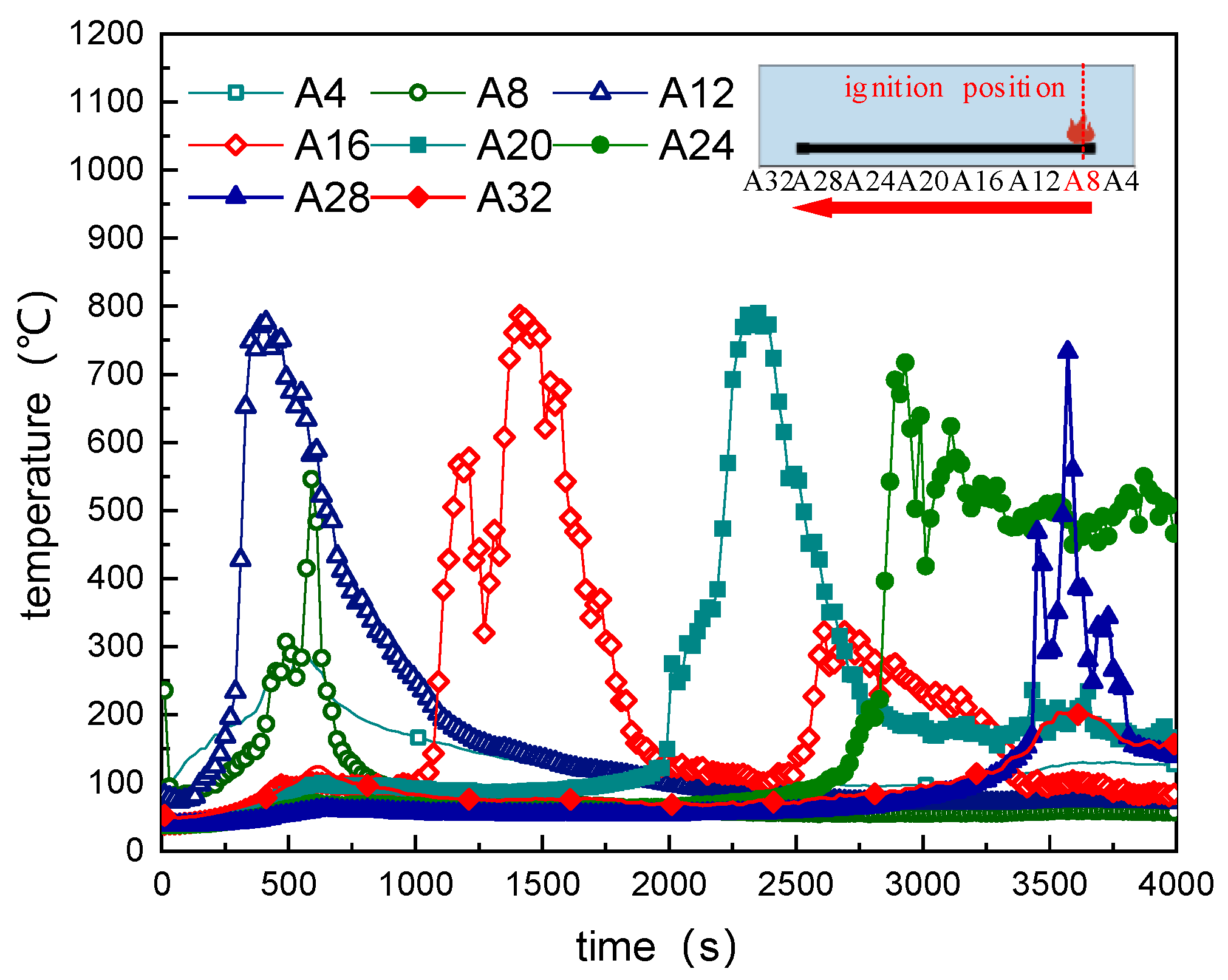
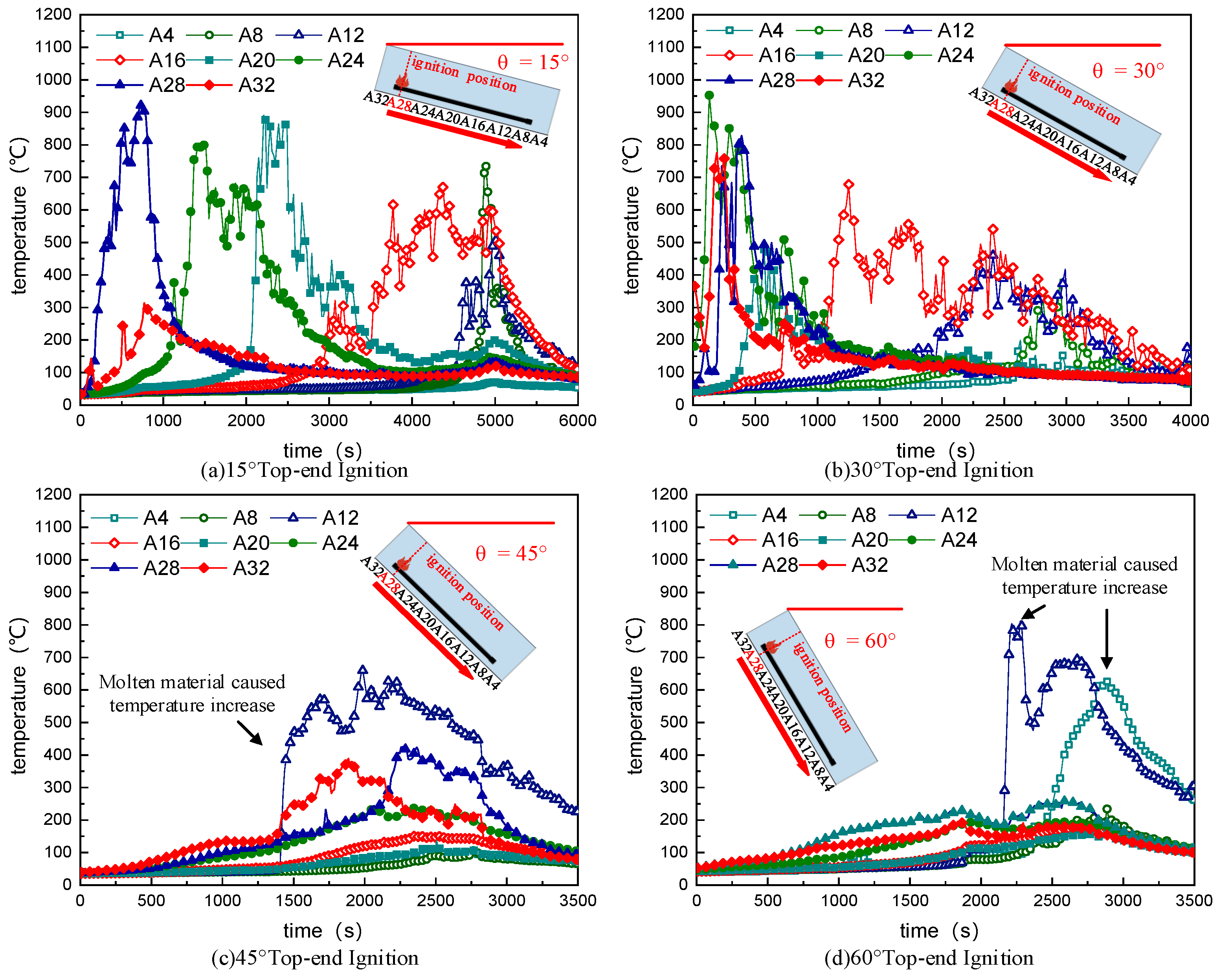
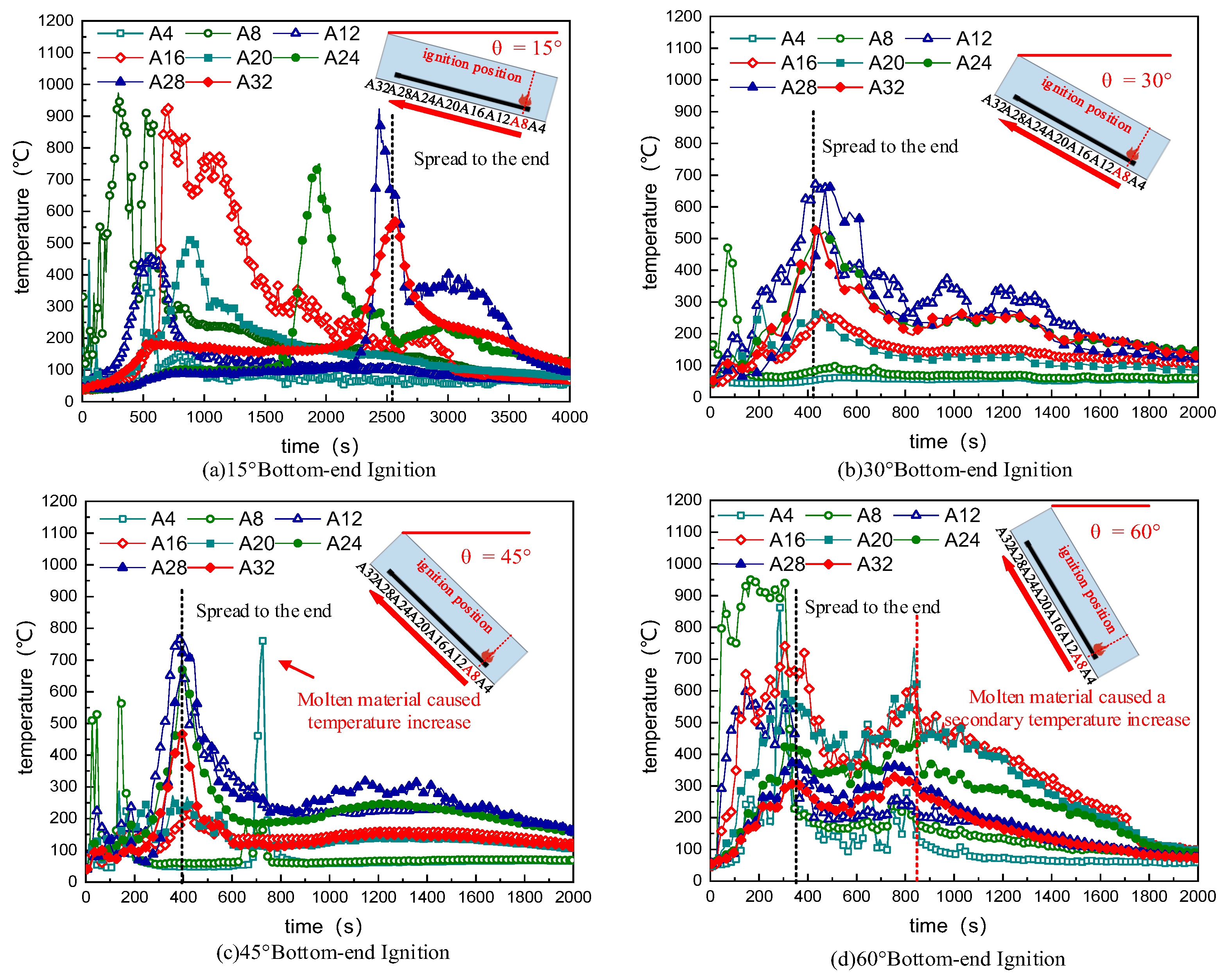
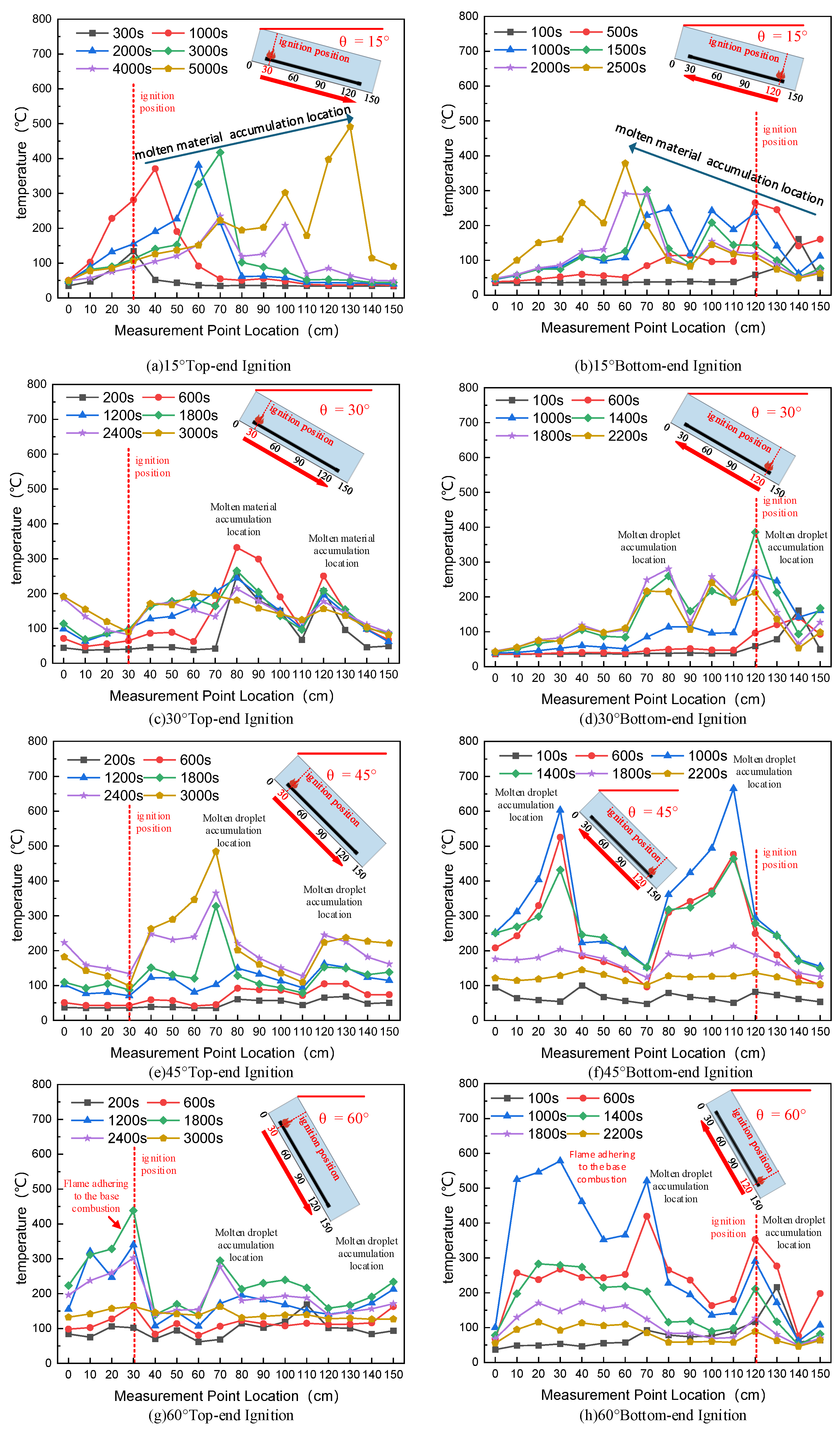
3.2. Temperature Analysis in Covered Cable Trays at Different Tilt Angles

The series of temperature curves for cable combustion in a covered cable tray under horizontal laying conditions are shown in Figure 4. In this figure, curve A8 represents the temperature near the ignition point, while curve A32 represents the temperature near the end of the combustion zone.
The temperature curves showed that the initial combustion of the cable lasted for approximately 250 s. At this time, significant temperature increase occurred at the A8 location, and due to the effect of heat conduction along the cable core, significant temperature increase also occurred at the A12 location, with the flame size beginning to increase. The temperature reached its peak at 500 s. Subsequent measurement points also experienced some temperature rise, which was due to the incomplete initial combustion of the cable, generating a large amount of smoke. Affected by the cover plate, the smoke spread horizontally, raising the temperature at subsequent measurement points. Around 1600 s, the flame spread to the A16 location, and by 2800 s, it had reached the A20 location. Based on the spacing of the measurement points and the moments of significant temperature rise, the fire spread rate in the middle section of the cable tray under horizontal conditions was relatively stable, and the combustion duration at each location was also relatively balanced, ranging from 600 to 800 s. It is worth noting that the temperature rise at A12 occurred earlier than at A8. After ignition, the flame was small in scale, and the thermocouple at A8 warmed up slowly. However, when the flame spread to A12, the flame size increased, and the temperature at A12 rose significantly. At this point, the A4 location, after burning and producing molten material, formed a larger flame. Therefore, the temperature rise at A4 was mainly due to the combustion of the molten material, which lagged behind that at A12. When the fire spread to the A24 location, a different phenomenon was observed. The temperature at this location remained high for an extended period. This was because during the experiment, the measurement point recorded the temperature of the flame above the cable. After the fire had passed, the cable did not completely burn, and the cable core remained at a high temperature, resulting in a sustained high temperature that decayed slowly. This also reflected a characteristic of cable fires: after being exposed to fire, cables tend to accumulate molten material, leading to sustained high temperatures. If additional fuel or oxidizing agents are introduced later, re-ignition is highly likely.
The series of temperature curves for cables in a covered cable tray with four different tilt angles under top-end ignition are shown in Figure 5a–d. They present the temperature curves for tilt angles of 15°, 30°, 45°, and 60°, respectively. Curve A28 represents the temperature near the ignition point, while curve A4 represents the temperature near the end of the combustion zone. From the temperature curve at a tilt angle of 15°, it was observed that the small tilt angle reduced the heating effect of the flame and decreased the fire spread rate, making it slower than that of horizontal combustion. The fire spread rate was stable during the early and middle stages of combustion. However, it is worth noting that in the later stage of combustion, local overall combustion occurred, with A8 and A12 simultaneously experiencing rapid temperature increases. This was due to the accumulation of molten material and its flow towards the lower end of the cable in the later stage of combustion, which caused the temperature of the cable in the later stage to rise. At a tilt angle of 30°, the accelerated flow of molten material not only increased the fire spread rate, but also led to overall combustion in the early stage of combustion, with A28 and A24 almost simultaneously beginning to heat up and burn. In the later stage of combustion (A16, A12, A8), the accumulation of molten material increased the combustion time at the same location, resulting in prolonged overall combustion. As the tilt angle further increased to 45°, the preheating effect of the flame was relatively weak, and the fire spread mainly relied on the heating effect of the molten material flow. The temperature curve clearly showed that the fire spread in the early stage of combustion was significantly slower at a tilt angle of 45°. At the same time, the temperature was relatively low, significantly lower than that at small tilt angles. This is due to the fact that at large tilt angles, the flame preheating effect is minimal, the flame size is smaller, and the flame is tilted, resulting in reduced heating of the thermocouples on the upper cables. Therefore, the temperatures recorded by the thermocouples are relatively low. After a period of combustion, a certain amount of molten material formed on the cable and flowed along it. The molten material continuously increased, flowed along the cable to a specific location (A8), accumulated, and continuously heated the cable, causing it to ignite. Due to the tilt, the preheating effect of the flame front caused a significant temperature increase at A12. At the same time, the solid-phase heat conduction of the cable core also caused significant temperature increases at the front end of the cable (A32, A28), leading to compartmentalized combustion within the cable tray. At a tilt angle of 60°, the flame front had completely moved upward along the tilt direction of the cable tray. In this case, the preheating effect of the flame on the unburned area was extremely weak, and the maintenance of subsequent combustion spread almost entirely relied on molten material and solid-phase heat conduction of the cable core. Therefore, the combustion at the front end of the cable was slow, the flame size decreased, and the production of molten material slowed down. The combustion at the rear end occurred slightly later than at 45°. However, the increase in tilt angle accelerated the flow of molten material, causing it to reach the end area (A4) more quickly. This resulted in a significant temperature increase at A4 and sped up the fire spread rate. In summary, it could be concluded that under top-end ignition conditions, the tilt angle had a strengthening effect on the flow and combustion of molten material, which significantly influenced the combustion situation under top-end ignition. At a small angle (15°), the weakening of the flame preheating effect was more significant than the influence of molten material flow, resulting in a slower fire spread rate and a longer combustion time. As the tilt angle increased, the influence of molten material flow became more pronounced, accelerating the fire spread rate and leading to compartmentalized combustion, where the front end and the back end of the cable burned simultaneously.
The series of temperature curves for cables in a covered cable tray with four different tilt angles under bottom-end ignition are shown in Figure 6a–d. They provide the temperature curves for tilt angles of 15°, 30°, 45°, and 60°, respectively. Curve A8 represents the temperature near the ignition point, while curve A32 represents the temperature near the end of the combustion zone.
At a tilt angle of 15°, the small tilt angle allowed the flame to heat the unburned cable section, accelerating fire spread. At locations A16, A20, and A28, A32, the heating effect of the flame front caused the adjacent positions to experience significant simultaneous temperature rises. Meanwhile, the flow of molten material resulted in a secondary temperature rise at each location. As the tilt angle increased, a significant concentrated temperature rise phenomenon occurred at various points. This was due to the enhanced preheating effect of the flame front and the significant reduction in combustion time as the tilt angle increased, resulting in jet-like flame combustion, which is also the most obvious combustion behavior when ignited from the bottom and is affected by the sensitivity of the thermocouples themselves. Nevertheless, it can be observed from the figure that the temperature rise at A12 occurred slightly earlier than at other locations. Notably, at a tilt angle of 45°, a significant temperature increase occurred at A4 at 350 s. A4 is at the lower end of the cable. This was because in the middle and later stages of combustion, the overall flame size decreased, allowing molten material to flow downward instead of being completely consumed in the middle section. The accumulated molten material reached the end and reignited after accumulating sufficient heat, causing a significant temperature increase at the end position. At a tilt angle of 60°, simultaneous temperature increases occurred at multiple measurement points, with combustion temperatures exceeding 300 °C. A collective temperature drop occurred at 400 s, followed by a collective temperature rise at 600 s. This was because the intense combustion caused molten material to form at each location, further extending the combustion time. In summary, it could be concluded that under bottom-end ignition conditions, as the tilt angle increased, the preheating effect of the flame accelerated, and downstream combustion intensified. At large tilt angles, jet-like combustion occurred, leading to large-scale overall combustion. Meanwhile, the flow of molten material at different tilt angles caused a secondary temperature rise in the cables, reflecting a significant characteristic of cable fires: the spread of molten material can lead to the expansion of combustion zones or re-ignition at previously burned locations.

3.3. The Effect of Different Tilt Angles on Molten Material

The molten material had a significant impact on the combustion behavior of cables under different tilts. To further analyze the effect of tilt angles on molten material, Figure 7 presents the temperature curves of molten material under different tilt angles. The data measurement points were the T1–T16 points in Figure 2, which collected the temperature of the central cross-sectional floor of the cable tray. Comparing vertically across different tilt angles, it could be observed that as the tilt angle increased, the location where molten material accumulated became more concentrated. This was because the increase in tilt angle accelerated the flow of molten material, preventing it from dripping vertically and instead causing it to flow and accumulate at the lower end.
The location of concentrated accumulation is not only affected by the tilt angle, but it is also related to the position and intensity of combustion. The more intense the combustion was, the more quickly molten material was produced, and the closer the accumulation location was to the combustion site. Under top-end ignition conditions, the larger the tilt angle, the weaker the initial combustion intensity, resulting in less molten material being produced in the early stage. This molten material flowed downward and accumulated at the lower end. At tilt angles of 45° and 60°, it could be clearly observed that the overall floor temperature was relatively low in the early stage of combustion, while the temperature at the rear end of the cable was higher. After significant combustion began at the T5 position under a large tilt angle, that is, after 1800 s, the intensified combustion accelerated the production of molten material, leading to accumulation at the T8 position. It is worth noting that at a tilt angle of 60°, the front end of the cable experienced an increase in temperature. This was due to the floor being affected by the flame burning along the bottom, causing a temperature peak.
Under bottom-end ignition conditions, a comparison between tilt angles of 30° and 45° clearly showed that at 45°, the molten material accumulated significantly more than at 30°. This was because the larger the tilt angle, the more intense the initial combustion, the faster the flame spread, the quicker the molten material was produced, and the earlier it accumulated. As the tilt angle reached 60°, the accumulation location moved lower compared to that at 45°. This was because the increase in combustion intensity from 45° to 60° was not significant, but the flow speed of the molten material increased significantly, causing the accumulation location to move lower. Additionally, the flame burning along the bottom at a 60° tilt angle further heated the molten material, causing a secondary temperature rise and extending the combustion time. Similarly, at a tilt angle of 60°, the flame burning along the bottom heated the rear end of the floor, causing a significant temperature increase in the floor.

3.4. Analysis of Fire Spread Rate in Covered Cable Trays

Figure 8 presents the average fire spread rate curves for cable combustion in a covered cable tray. The results showed that there were significant differences in the fire spread rates between top-end and bottom-end ignition under different tilt angles. Due to the inclination, under the condition of top-end ignition, the flame size was relatively small and tilted. As a result, the thermocouples at the front of the combustion could not reach the specified threshold temperature, even though the flame continued to spread. Therefore, image and video data were chosen to determine the rate of fire spread. When the flame front reached a certain position, it was considered that the fire had spread to that location. Using video processing software, the video data were output as images at fixed time intervals (typically according to the video frame rate). By recording the flame positions, the average fire spread rate for the cable section could be calculated.
Figure 8 indicates that under top-end ignition conditions, the average fire spread rate of the cable increased continuously as the tilt angle increased. When the tilt angle reached 30°, a significant acceleration in the fire spread rate was observed. However, as the angle continued to increase, the rate of increase gradually leveled off. In contrast, under bottom-end ignition conditions, when the tilt angle changed from horizontal to 15°, the average fire spread rate decreased. This was because at this angle, the preheating effect of the flame on the unburned area was weakened, and the tilt of the cable tray did not significantly enhance the flow of molten drips, leading to a reduction in the fire spread rate, with an average attenuation of 28%. When the tilt angle further increased to 30° under bottom-end ignition conditions, the flame began to closely adhere to the cable surface, thereby enhancing the preheating effect on the unburned area. Meanwhile, the presence of the top cover plate strengthened radiative heat transfer, significantly accelerating the fire spread rate, with an average spread rate reaching 3.5 mm/s. Under top-end ignition conditions, convective heat transfer was further weakened, but the flow of molten material along the cable was enhanced, increasing the preheating effect on the unburned area and thus promoting combustion acceleration. As the tilt angle continued to increase, the rate of increase in the fire spread rate slowed down under both top-end and bottom-end ignition conditions, because further increases in angle did not introduce new factors that enhanced heat transfer. Overall, the fire spread rate under bottom-end ignition conditions was consistently higher than that under top-end ignition conditions. After the tilt angle exceeded 30°, the fire spread rate under bottom-end ignition was approximately twice that under top-end ignition. Regardless of the ignition position, the flame spread rate significantly increased at 15–30°.

4. Conclusions

This study experimentally investigated the combustion temperature distribution and flame propagation characteristics of cross-linked polyethylene cables in a covered cable tray under different laying angles and ignition positions, and the following conclusions were drawn.
Under top-end ignition, the tilt angle has a strengthening effect on the flow and combustion of molten material, which significantly impacts the combustion situation in the upstream direction. At small angles, the weakening of the flame preheating effect has a greater influence than the flow of molten material, resulting in longer combustion times. As the tilt angle increases, the influence of molten material flow becomes more pronounced, and accumulation of molten material becomes more concentrated, leading to compartmentalized combustion, where the front end and the end of the cable burn simultaneously.
Under bottom-end ignition, as the tilt angle increases, the preheating effect of the flame accelerates, and downstream combustion intensifies. At large tilt angles, jet-like combustion occurs, leading to large-scale overall combustion. Meanwhile, the flow of molten material at different tilt angles intensifies, causing the accumulation of molten material at the front end of the combustion, which results in a secondary temperature rise in the cable.
Through quantitative analysis of the fire spread rate, it was found that the fire spread rate is significantly affected by the direction of flow (upstream or downstream) and the angle of inclination. Under top-end ignition, the fire spread rate initially decreased slightly and then increased, with a relatively small change in magnitude. Under bottom-end ignition, the fire spread rate increased with the tilt angle. Regardless of the ignition position, the flame spread rate significantly increases at 15–30°. Therefore, in actual cable installation processes, cables within covered troughs should avoid large-angle inclinations and should not exceed 15°.
Finally, the existing research mainly focuses on the impact of inclination angles and different ignition positions on the fire spread process in cable fires within covered trays. However, based on the limitations of the existing research and the diversity of cable fires, there are the following issues: the combustion behavior of different cable materials and cable structures, such as stepped cable structures and vertical cable structures, shows significant differences, and there is a need for a clearer understanding of the mechanisms of preheating and molten materials on combustion. These problems need to be further explored and revealed by future research.

Author Contributions

C.C.: conceptualization, methodology, and writing—review and editing. Y.B.: writing—original draft preparation, data curation, and investigation. B.Z.: visualization and editing. J.Z.: supervision and project administration. Y.W.: validation. All authors have read and agreed to the published version of the manuscript.

Funding

This work was supported by the National Natural Science Foundation of China (grant No. 72091512). The authors appreciate the support deeply.

Institutional Review Board Statement

Not applicable.

Informed Consent Statement

Not applicable.

Data Availability Statement

The raw data are held by the author and may be made available upon request.

Conflicts of Interest

Authors Jia Zhang and Yuhuai Wang were employed by the company State Grid Jiangsu Elect Power Co., Ltd., Nanjing Power Supply Co. The remaining authors declare that the research was conducted in the absence of any commercial or financial relationships that could be construed as a potential conflict of interest.

References

  1. Godakandage, R.; Weerasinghe, P.; Gamage, K.; Adnan, H.; Nguyen, K. A Systematic Review on Cavity Fires in Buildings: Flame Spread Characteristics, Fire Risks, and Safety Measures. Fire 2024, 7, 12. [Google Scholar] [CrossRef]
  2. Guo, D.; Wang, J.; Li, S.; Shi, C.; Zhou, Y.; Li, P.; An, X.; Xiong, Y. Numerical study on smoke temperature and exhaust efficiency in electric cable tunnel. J. Phys. Conf. Ser. 2024, 2728, 012010. [Google Scholar] [CrossRef]
  3. Cai, J.; Guo, W.; Ji, H.; Li, H.; Ren, Z.; Pan, Z.; Men, Y. Study on the Configuration and Fire-Resistant Property of Cable Tunnel Fireproof Clapboard Based on Equivalent Fire Condition Testing. Fire 2024, 7, 357. [Google Scholar] [CrossRef]
  4. Niu, Y.; Li, W. Simulation Study on Value of Cable Fire in the Cable Tunnel. Procedia Eng. 2012, 43, 569–573. [Google Scholar] [CrossRef]
  5. Mo, S.; Zhang, J.; Liang, D.; Chen, H.-Y. Study on Pyrolysis Characteristics of Cross-linked Polyethylene Material Cable. Procedia Eng. 2013, 52, 588–592. [Google Scholar] [CrossRef]
  6. An, W.; Wang, X.; Tang, Y.; Wang, T.; Lu, J. Influence of cable inclination angle and longitudinal ventilation on temperature distribution during cable fire in utility tunnel. Case Stud. Therm. Eng. 2021, 27, 101304. [Google Scholar] [CrossRef]
  7. Zhang, J.; Wang, Y.; Lu, X. Study on melting behavior of polymers during burning. Fire Saf. Sci. 2005, 8, 637–646. [Google Scholar] [CrossRef]
  8. Wang, Y.; Zhang, J. Thermal stabilities of drops of burning thermoplastics under the UL94 vertical test conditions. J. Hazard. Mater. 2013, 246, 103–109. [Google Scholar] [PubMed]
  9. Xie, Q.; Zhang, H.; Ye, R. Experimental study on melting and flowing behavior of thermoplastics combustion based on a new setup with a T-shape trough. J. Hazard. Mater. 2009, 166, 1321–1325. [Google Scholar] [CrossRef] [PubMed]
  10. Xie, Q.; Tu, R.; Wang, N.; Ma, X.; Jiang, X. Experimental study on flowing burning behaviors of a pool fire with dripping of melted thermoplastics. J. Hazard. Mater. 2014, 267, 48–54. [Google Scholar] [CrossRef] [PubMed]
  11. Kandola, B.K.; Price, D.; Milnes, G.J.; Da Silva, A. Development of a novel experimental technique for quantitative study of met dripping of thermoplastic polymers. Polym. Degrad. Stab. 2013, 98, 52–63. [Google Scholar] [CrossRef]
  12. Kandola, B.K.; Ndiaye, M.; Price, D. Quantification of polymer degradation during meltdripping of thermoplastic polymers. Polym. Degrad. Stab. 2014, 106, 16–25. [Google Scholar] [CrossRef]
  13. Leung, C.H.; Staggs, J.E.J.; Brindley, J.; McIntosh, A.C.; Whiteley, R.H. The effects of an inertcentral core on the thermal pyrolysis of an electrical cable. Fire Saf. J. 2000, 34, 143–168. [Google Scholar] [CrossRef]
  14. Liu, M.; Zhou, Y.; Li, J.; Chen, Y.; Zhao, S.; Xu, T.; Wang, F.; Zhuang, Z. An experimental study on the combustion characteristics of YJV and YC cables in urban utility tunnels. Case Stud. Therm. Eng. 2025, 69, 105986. [Google Scholar] [CrossRef]
  15. Huang, X.; Zhu, H.; Peng, L.; Zheng, Z.; Zeng, W.; Bi, K.; Cheng, C.; Chow, W. Thermal Characteristics of Vertically Spreading Cable Fires in Confined Compartments. Fire Technol. 2019, 55, 1849–1875. [Google Scholar] [CrossRef]
  16. Chen, J.; Qin, S.; Zhao, X.; Tong, Y.; Fan, M. Experimental study on the influence of layer number and initial ignition location on burning characteristic of multi-layer cable fire. Fire Saf. J. 2025, 153, 104368. [Google Scholar] [CrossRef]
  17. Wang, T.; Ding, J.; Zhang, T.; Liu, P.; Yu, X.; Wang, Y.; An, W. Modelling of heat release rate of horizontal cable trays fire in long-narrow confined spaces. Tunn. Undergr. Space Technol. Inc. Trenchless Technol. Res. 2024, 150, 105831. [Google Scholar] [CrossRef]
  18. Zavaleta, P.; Bascou, S.; Suard, S. Effects of cable tray configuration on fire spread. In Proceedings of the 15th International Conference and Exhibition on Fire and Materials, San Francisco, CA, USA, 6–8 February 2017; Volume 1, pp. 17–33. [Google Scholar]
  19. Verma, N.; Hostikka, S.; Vaari, J.; Korhonen, T. Adapted FLASHCAT methodology to model horizontal cable tray fires using computational fluid dynamics. Fire Saf. J. 2023, 138, 103814. [Google Scholar] [CrossRef]
  20. Zavaleta, P.; Hanouzet, R.; Beji, T. Improved Assessment of Fire Spread over Horizontal Cable Trays Supported by Video Fire Analysis. Fire Technol. 2019, 55, 233–255. [Google Scholar] [CrossRef]
  21. GB 50217-2018; Standard for Design of Cables of Electric Power Engineering. China Planning Press: Beijing, China, 2018.
Figure 1. Schematic diagram of the experimental setup.
Fire 08 00272 g001
Figure 2. Arrangement of thermocouple measurement points on the center cross-section.
Fire 08 00272 g002
Figure 3. Typical flame shapes at different moments of cable combustion in covered cable trays at various tilt angles.
Fire 08 00272 g003
Figure 4. Temperature curves of cables in a covered cable tray under horizontal laying conditions.
Fire 08 00272 g004
Figure 5. Temperature curves of cables in a covered cable tray with different tilt angles under top-end ignition.
Fire 08 00272 g005
Figure 6. Temperature curves of cables in a covered cable tray with different tilt angles under bottom-end ignition.
Fire 08 00272 g006
Figure 7. Temperature curves of molten material in a covered cable tray at different tilt angles.
Fire 08 00272 g007
Figure 8. Fire spread rate curves of cables in a covered cable tray at different tilt angles.
Fire 08 00272 g008
Table 1. Summary of the experimental conditions.
Test IDCable Length (m)Tilt AngleIgnition Position
A11Right end
A2115°Top end
A3115°Bottom end
A4130°Top end
A5130°Bottom end
A6145°Top end
A7145°Bottom end
A8160°Top end
A9160°Bottom end
Disclaimer/Publisher’s Note: The statements, opinions and data contained in all publications are solely those of the individual author(s) and contributor(s) and not of MDPI and/or the editor(s). MDPI and/or the editor(s) disclaim responsibility for any injury to people or property resulting from any ideas, methods, instructions or products referred to in the content.

