Article

Research on Control of Ammonia Fuel Leakage and Explosion Risks in Ship Engine Rooms

College of Merchant Marine, Shanghai Maritime University, Shanghai 201306, China
*
Author to whom correspondence should be addressed.
Fire 2025, 8(7), 271; https://doi.org/10.3390/fire8070271
Submission received: 4 June 2025 / Revised: 25 June 2025 / Accepted: 8 July 2025 / Published: 9 July 2025
(This article belongs to the Special Issue Clean Combustion and New Energy)

Abstract

Due to the unique physicochemical properties of ammonia fuel, any leakages in the engine room will inevitably endanger ship safety. This study focuses on investigating the diffusion behavior of ammonia fuel within the engine room during ship navigation after leakage, aiming to identify hazardous points and implement measures, such as installing air-blowing and extraction devices, to mitigate the risks. To address potential leakage risks in ammonia-fueled ships, a simplified three-dimensional computational model was developed based on ship design drawings and field investigations. ANSYS Fluent software (2024 R2) was employed to simulate ammonia fuel leakage from pipelines and equipment, analyzing the diffusion patterns of leakage at different locations and evaluating the impact of adding air-blowing and extraction devices on leaked fuel in the engine room. The simulation results demonstrate that leakage at point 3 poses the greatest operational hazard, and ammonia fuel leakage during navigation generates combustible gas mixtures within the explosion limit range around the main engine, severely threatening both vessel safety and crew lives. Installing air-blowing and extraction devices in high-risk areas effectively reduces the explosion limit range of ammonia fuel, with air outlet 3 showing optimal mitigation effectiveness against ammonia fuel leakage during ship transportation.

1. Introduction

The 80th session of the IMO’s Marine Environment Protection Committee (MEPC), in 2023, adopted the 2023 IMO Strategy on Reduction of GHG Emissions from Ships, accelerating the transition toward net zero greenhouse gas emissions in international shipping [1]. Nations are actively pursuing low-carbon and zero-carbon alternative fuels as viable solutions, with ammonia and methanol currently recognized as the most promising energy options for marine propulsion systems. According to Clarksons Research data, 552 alternative fuel-powered vessels were ordered globally in 2023, representing 45% of total new vessel orders, while the proportion of alternative fuel-capable vessels is projected to reach 23% by 2030 [2]. This demonstrates the acceleration in the adoption of ammonia-fueled combustion technologies in marine engine applications, particularly through the use of dual-fuel engine configurations that are optimized for nitrogen-based emissions control and flame stability during compression ignition cycles.
Currently, ammonia fuel production technology is relatively mature, with established standards and regulations, enabling cost-effective manufacturing, storage, and transportation, which provides a solid foundation for its use in marine applications. Despite these advantages, ammonia’s high toxicity poses significant risks, as inhalation can cause respiratory tract damage. Consequently, stringent measures must be implemented throughout the ammonia fuel supply chain, including production, transportation, and utilization stages, to prevent leakage incidents. In 2018, the car carrier “Auto Banner” experienced a vehicle deck fire during loading operations at a Libyan port, where flames rapidly spread among over 2000 used vehicles, resulting in substantial economic losses [3]. Similarly, in 2020, the Höegh Xiamen car carrier sustained a fire incident off the coast of Florida, USA, requiring eight days of continuous firefighting before full extinguishment was achieved [4]. Jang et al. [5] investigated and compared state-of-the-art safety regulations, rules, standards, and guidelines for ammonia-fueled ships using classification society reports and international codes, such as the IGF Code.
Numerical simulation technology, accompanied by the rapid advancement of computer technology, has now become a core method for investigating gas leakage, diffusion, and explosion phenomena. Regarding explosion mechanisms and disaster prevention/control, explosion characteristics within confined spaces (such as instantaneous shock and sustained pressure loads) and the influencing factors are a current research focus [6]. In this field, ANSYS Fluent software is widely used for simulating explosions in complex scenarios; Zhang et al. [7] developed a computational fluid dynamics (CFD) model to analyze the physical behavior of cylindrical natural gas storage tanks, validating the simulation results against experimental data to enhance spill risk assessments and optimize tank/containment dike design; Atherton et al. [8] conducted numerical simulations of tank storage systems, yielding insights critical for mitigating the scale and severity of catastrophic accidents; Zhao et al. [9] explored the coupling of leakage and explosion simulations to ensure scenario realism, examining explosion hazards through the use of parameters such as overpressure, explosion temperatures, and mass fractions of combustion products; Zhang et al. [10] found through the use of simulations that the shape of the vapor cloud has an even greater impact on the explosion intensity than the total fuel mass. Dynamic evolution studies combining experiments and simulations have elucidated the influence of the vent size on the explosion pressure and flame structure [11], and validated the applicability of Detached Eddy Simulation (DES) and the Thickened Flame Model (TFLES) for analyzing explosion evolution [12].
Safety research on specific combustible gases and scenarios shows distinct characteristics. In the fields of liquefied natural gas (LNG) and natural gas, the research focus lies on analyzing ship leakage accidents [13] and developing prevention and control strategies for vapor cloud explosions within pipeline corridors. Additionally, the construction of predictive models for gasoline vapor dispersion explosions [14], and investigations into the spatial overpressure distribution characteristics of solid and liquid fuel cloud explosions [15], have expanded the scope of traditional combustible material research. Studies on multi-factor coupling and risk assessments have revealed the sensitivity of the water temperature and level to steam explosions [16], and the chain-reaction disaster effects in complex environments caused by the interaction of pressure waves from multi-source explosions [17]. The hydrogen explosion risk assessment practice developed for the EU DEMO reactor [18] and quantitative ventilation system design research [19] have further advanced the application of risk prediction models in practical engineering.
In gas leakage and diffusion research, the application of CFD enables scholars to reveal the dynamic laws governing the coupling effects of multiple factors. For example, Song et al. [20] established a three-layer dynamic simulation model for stratified liquefied natural gas (LNG), involving boil-off gas (BOG), LNG, and liquid nitrogen, which involved simulating transient behaviors under varying sloshing periods and amplitudes; Verfondern et al. [21] simulated cryogenic liquid dispersion and evaporation using shallow-layer differential equations, characterizing liquid hydrogen (LH2) spill behavior under diverse conditions; Phan et al. [22] systematically identified the risks associated with ammonia release, diffusion, and hazardous zones, establishing standardized procedures for assessing leakage risks in engine rooms; Luketa-Hanlin et al. [23] conducted extensive experimental and analytical studies to predict hazards associated with liquefied natural gas (LNG) storage and transportation in marine environments; Li et al. [24] focused on the ship engine room environment. Their research demonstrated that during small-scale leaks, combustible concentrations of natural gas primarily accumulate in localized areas, while medium-scale leaks tend to form diffusion clouds in the upper regions. Regarding methodological innovation, Liu et al. [25] effectively enhanced the prediction accuracy for leaks under various working conditions by combining Particle Image Velocimetry (PIV) technology with CFD; Liu et al. [26] concentrated on ship-to-ship bunkering processes, employing CFD simulations to analyze ammonia leakage scenarios, including the relative orientation of leakage directions in regard to vessel alignment and wind patterns. The analysis of key influencing factors confirms that the leak rate, environmental conditions, and leak orifice geometric parameters play a decisive role in the diffusion process [27,28,29,30].
Synthesis of the existing research reveals three major trends: First, the accuracy of CFD and finite element analysis tools (e.g., ANSYS Fluent) continue to improve, enabling multi-physics field coupling, such as the combined application of PIV and CFD [31]. Second, safety strategies are shifting from passive prevention and control towards active suppression, exemplified by the adoption of ultra-fine water mist [32] and optimized ventilation systems [33]. Third, the scope of application extends from traditional industrial facilities to new energy sectors and extreme environments. Future research needs to focus on breakthroughs in fine-scale modeling under complex boundary conditions, the development of novel explosion suppression materials and technologies, and dynamic multi-scale supply chain risk assessments. Based on an analysis of the literature, although certain achievements exist in terms of the research on ship fuel leakage and explosions, exploration into the safety of ammonia dual-fuel ship engine rooms remains insufficient. In particular, simulation studies targeting the coupled processes of gas leakage, diffusion, and explosion within this specific environment are lacking. Compared to other confined spaces, the ship engine room structure possesses unique characteristics. Influenced by vessel motion and the external environmental conditions, its internal layout, ventilation, and other factors are more complex than other confined spaces, significantly increasing the safety challenges and rescue difficulty.
The innovation of this study is primarily demonstrated in regard to the following aspects: Addressing the fragmented nature of previous ammonia leakage and explosion simulation research, this paper employs ANSYS Fluent software to construct a more realistic numerical model to simulate the coupled process of gas leakage and explosion within a ship engine room. This provides a basis for future ship design and the formulation of personnel safety regulations. Based on the leakage and explosion simulation results, this paper assesses the hazards to human health from the perspectives of the leakage rate, temperature, and subsequent ammonia toxicity, proposing recommendations and measures to mitigate these hazards. Concurrently, it analyzes the diffusion patterns of ammonia post-leakage, offering a crucial reference for accident rescue operations. The structure of this paper is arranged as follows: Section 1 details the results of the literature review, clarifying the study’s innovation and core contributions; Section 2 systematically elaborates the theoretical model framework for leakage and diffusion, presenting the geometric model, boundary conditions, and performing mesh independence verification; Section 3 presents and analyzes the numerical simulation results in terms of leakage and explosion, and explores the impact of different ventilation measures on ammonia leakage and the role of related factors.

2. Numerical Model and Validation

2.1. The Basic Theories of Leakage, Diffusion, and Explosion

The simulation framework for analyzing fuel leakage dynamics in marine pipeline systems integrates the core principles of fluid mechanics with advanced CFD methodologies. The ANSYS Fluent software employs multi-physics computational analyses of ammonia (NH3) dispersion through the rigorous implementation of mass continuity, momentum conservation, energy balance, and species transport formulations. The variable-density nature of ammonia during accidental release scenarios, evidenced by Reynolds number analysis, necessitates turbulent flow characterization rather than laminar approximations. This study adopts the industry standard k-epsilon turbulence closure model to precisely capture leakage dynamics, solving the coupled transport equations for turbulent kinetic energy (k) and its dissipation rate (ε). This dual-equation approach mathematically quantifies both turbulence intensity and energy dissipation patterns, providing a complete description of the turbulent momentum and mass transfer mechanisms within complex flow regimes.
The governing equations for the variable-density turbulent fluid dynamics in this study are formulated as follows: The continuity equation (Equation (1)) describes the gas mixture density (ρ) and velocity components (ui) in u, v, and w directions. The momentum conservation equation (Equation (2)) incorporates the air density (ρa), absolute pressure (P), gravitational acceleration (g), and fluid dynamic viscosity (μ). Energy conservation is governed by Equation (3), where T denotes temperature, Cp represents the specific heat at a constant pressure, k indicates thermal conductivity, and St encompasses the heat sources and viscous dissipation terms from the mechanical energy conversion. The turbulent kinetic energy (k) transport equation (Equation (4)) and turbulent dissipation rate (ε) equation (Equation (5)) complete the k-ε model framework: Gk represents the turbulence production from the mean velocity gradients; Gb accounts for buoyancy-induced turbulence generation; YM characterizes the compressibility effects through dilatation dissipation; σk (Prandtl number for k, 1.0) and σε (1.3 for ε) govern turbulent diffusion; empirical constants C1ε = 1.44, C2ε = 1.92, and C3ε = 0.80 regulate the production/destruction balance; and μ denotes laminar viscosity, while μt represents turbulent viscosity [34].
ρ t + ρ u j x j = 0
ρ u i t + x j ρ u i u j = P x i + x j μ u i x j + ρ ρ a g
( ρ u j T ) x j + ( ρ T ) t = x j k C p T x j + S T
ρ k t + ρ k u i x i = x j μ t σ k + μ k x j + G k + G b ρ ε Y M + S k
( ρ ε ) t + ( ρ ε u i ) x i = x j μ t σ ε + μ ε x j + C 1 ε ε k ( G k + G 3 ε G b ) C 2 ε ρ ε 2 k + S ε
The ANSYS Fluent-based computational framework addresses post-leakage ammonia combustion in marine engine compartments through the use of advanced numerical techniques that incorporate fundamental conservation principles (mass, momentum, energy) with finite volume discretization of reactive species transport (Equation (6)) [35]. In this formulation, Yf corresponds to the fuel mass concentration, σk specifies the turbulent Prandtl number (0.7), μe defines the effective viscous properties, Rm governs the combustion rate parameters, βj quantifies the molecular diffusion effects, and h represents thermodynamic enthalpy. This integrated methodology establishes a linkage between turbulent flow physics and chemical kinetic interactions, facilitating high-fidelity modeling of transient combustible mixture distributions and thermal energy transitions in confined premixed combustion environments.
t ( β v ρ m ) + x j β j ρ μ j m = x j β j μ e h σ k x j + R m

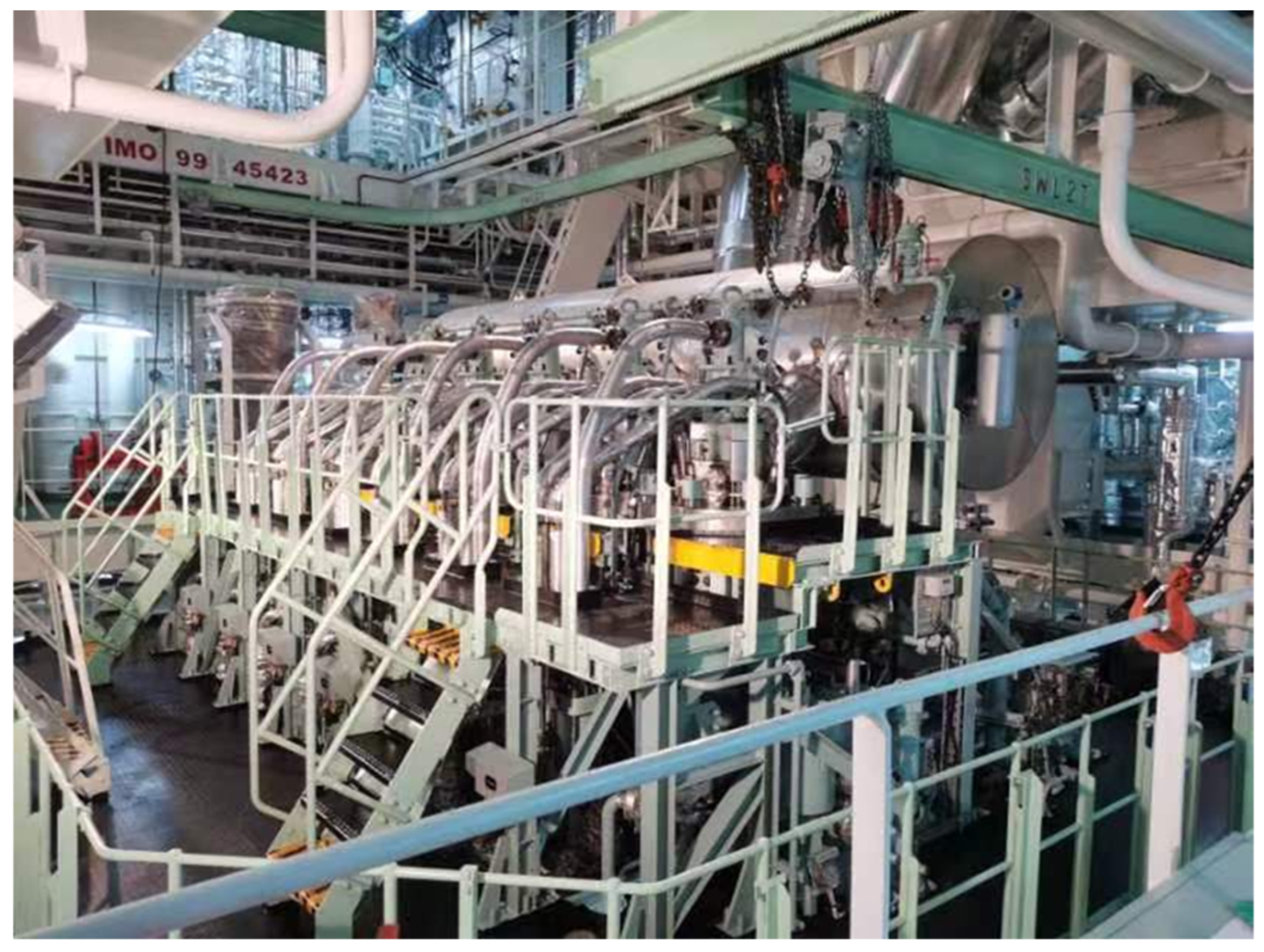
2.2. Establishment of the Cabin Model

The machinery space, serving as the core area for vessel power generation and energy supply, houses critical electromechanical systems, including the main engines, boilers, fuel oil systems, exhaust systems, lubrication systems, cooling systems, and fire safety installations. Certain machinery space configurations exhibit complex features, such as multi-deck arrangements, dense piping networks, and integrated automated control systems. The physical model of the ship’s machinery space is illustrated in Figure 1.
Under standard atmospheric conditions (101.325 kPa, 20 °C), with an air density of 1.205 kg/m3 and a dynamic viscosity coefficient of 17.9 × 10⁻⁶ Pa·s, fluid leakage from pipelines rapidly transitions to a turbulent flow. To satisfy ANSYS Fluent’s resolution, computational capacity, and modeling efficiency requirements for simulating ammonia fuel leakage and explosion scenarios, this study employs a simplified machinery space model of the SDARI-designed “Jiangnan Shipyard 1100TEU Jinjiang-class” (Shanghai, China) container vessel. The simulation framework ignores minor components and streamlines the geometries of major equipment (main engine, air compressors, oil tanks), while prioritizing the piping system. The physical model, developed using SolidWorks 3D modeling software (SolidWorks 2024) and meshed via Fluent Meshing for surface and volume grid generation, is presented in Figure 2 [36].

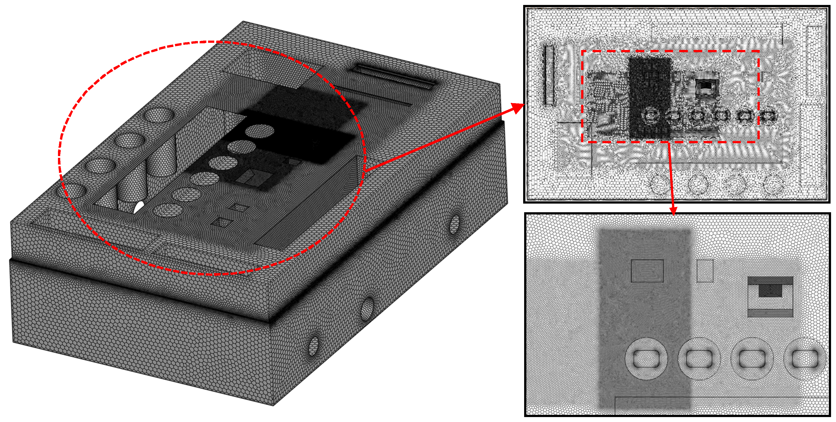
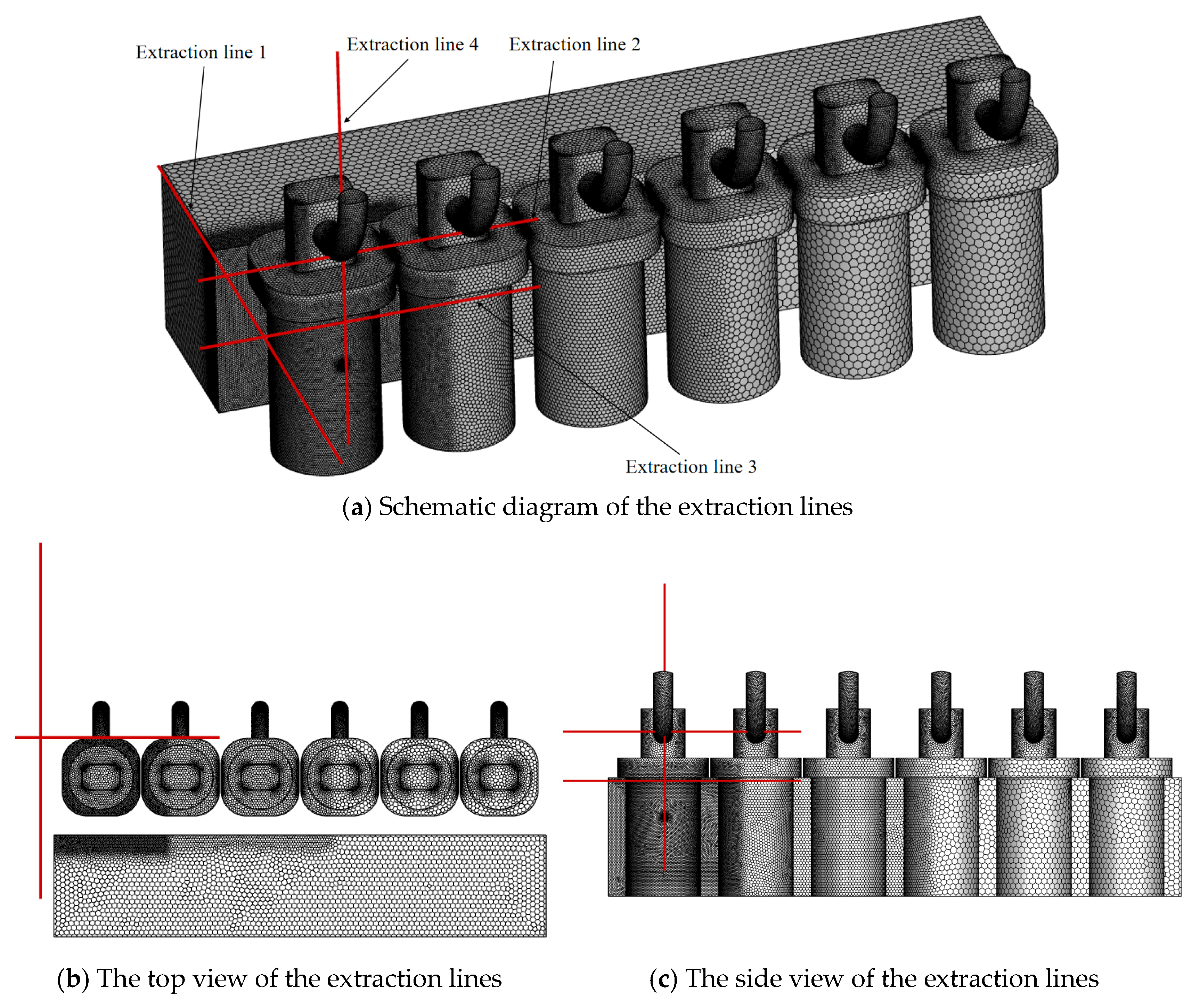
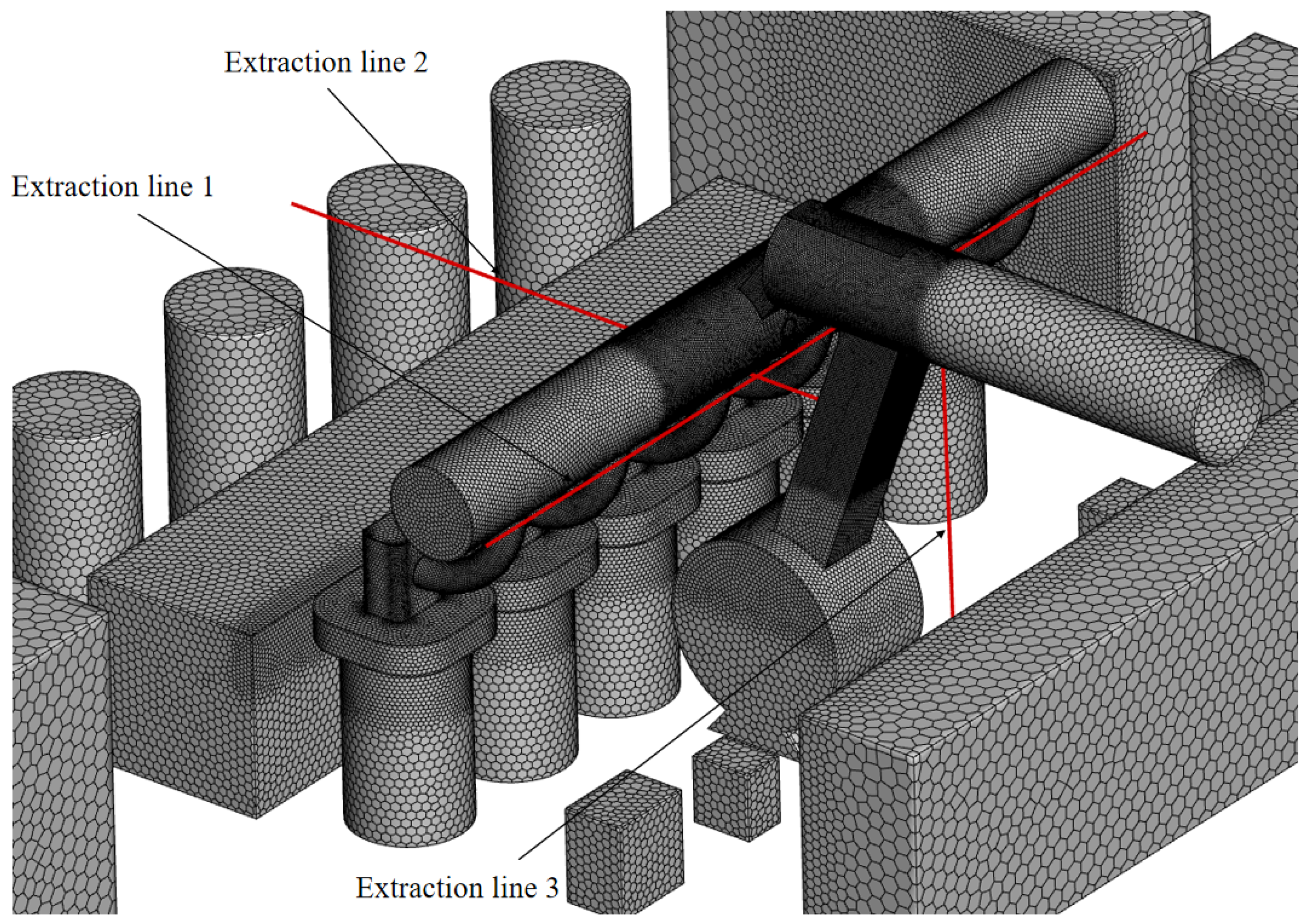
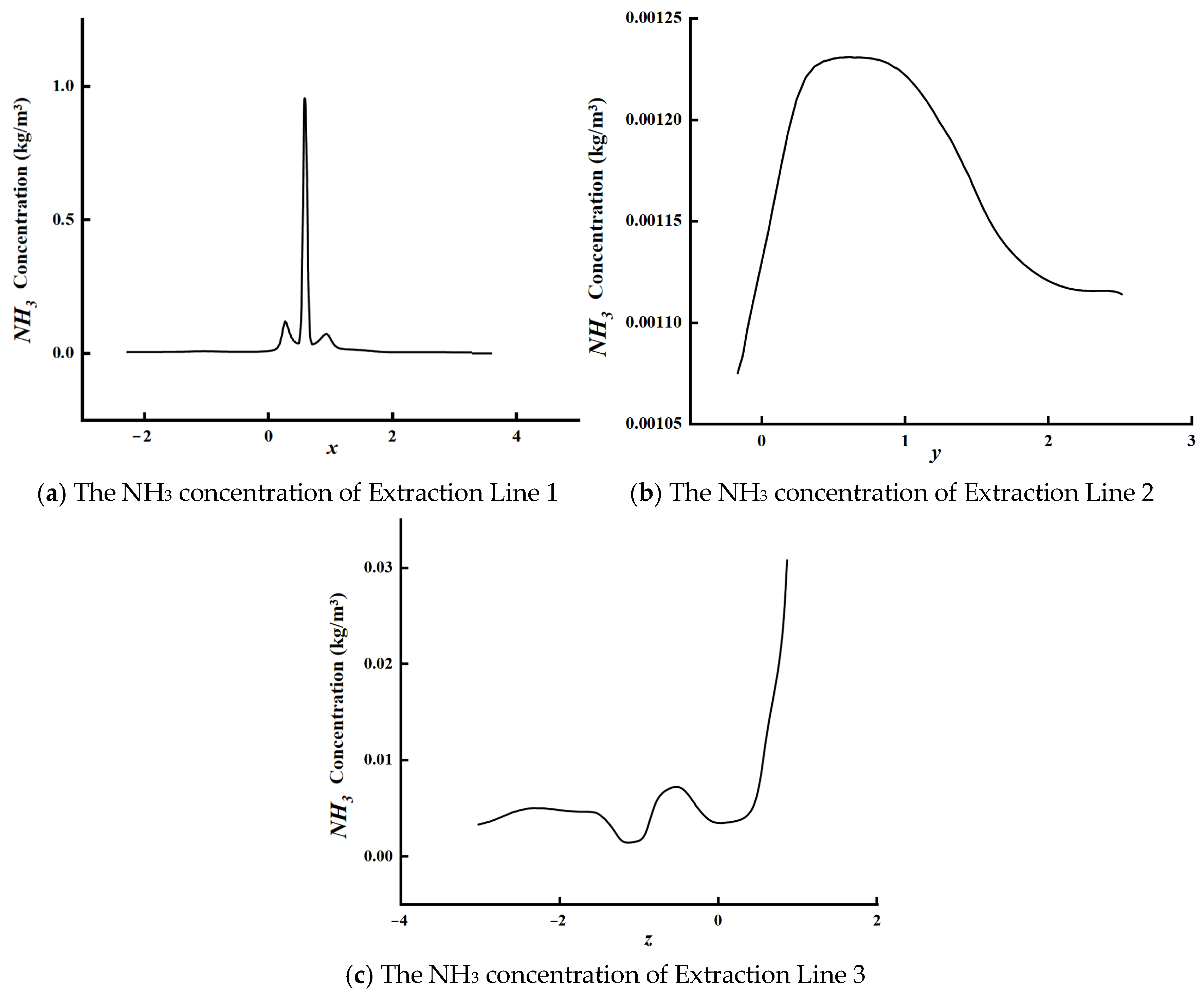
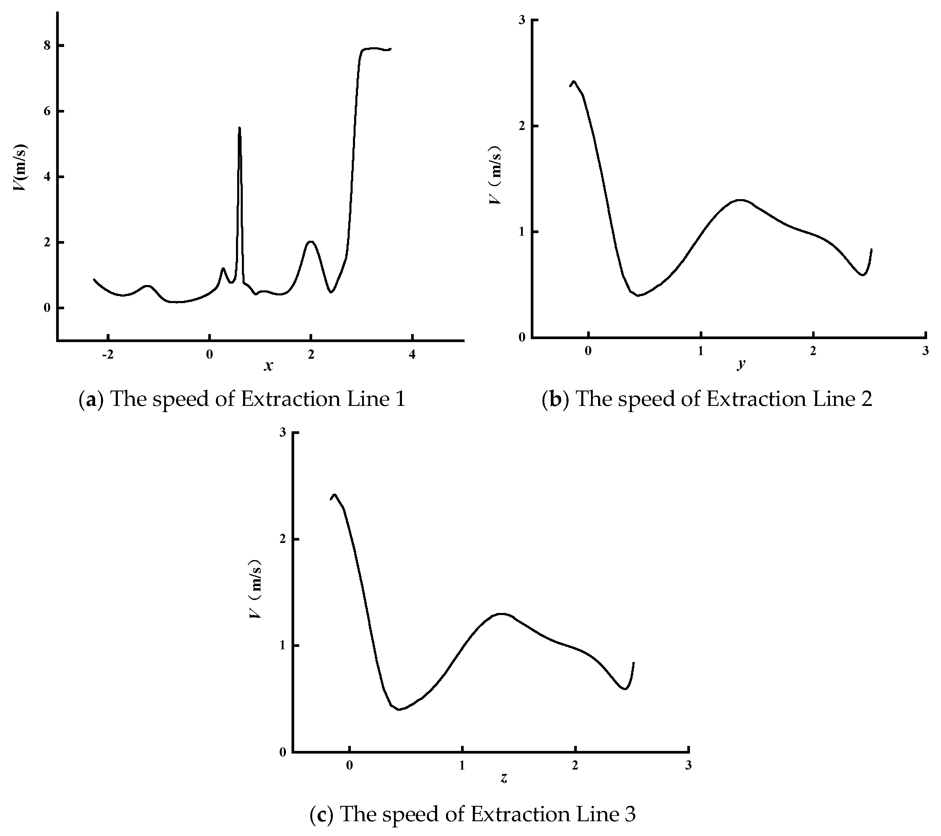
2.3. Grid Independence Verification

This study utilizes CFD software Fluent Meshing for grid generation. To ensure computational accuracy, while preventing excessive grid density from compromising the efficiency, surface mesh refinement is applied to regions with high curvature variations and complex structural features in the computational model, as illustrated in Figure 3.
To eliminate the influence of the grid density on computational accuracy, three grid configurations, A (coarse mesh), B (medium mesh), and C (fine mesh), were generated. Four monitoring points were strategically selected across the model for data acquisition, with their spatial distribution illustrated in Figure 4.
Three mesh configurations with grid counts of 650,000, 3.86 million, and 8.32 million were implemented. Grid independence verification was conducted using airflow velocity and temperature data from the machinery space monitoring points, which were used as validation metrics, with the computational results detailed in Table 1 and Table 2.
As shown in Table 1, the temperature discrepancy between Mesh A and Mesh C at Monitoring Point 1 is 0.42%, while the difference between Mesh B and Mesh C is reduced to 0.08%. At Monitoring Point 2, the temperature deviation between Mesh A and Mesh C reaches 0.62%, whereas Mesh B and Mesh C exhibit a smaller discrepancy of 0.20%. For Monitoring Point 3, the Mesh A–C temperature error is 0.29%, compared to a minimal 0.12% variance between Mesh B and C. Similarly, Monitoring Point 4 demonstrates a 0.35% temperature difference between Mesh A and C, with Mesh B and C showing only a 0.07% deviation.
As shown in Table 2, the velocity discrepancy between Mesh A and Mesh C at Monitoring Point 1 is 8.33%, whereas Mesh B and Mesh C exhibit a significantly smaller error of 1.69%. At Monitoring Point 2, the velocity difference between Mesh A and C reaches 12.20%, compared to a reduction to 2.44% variance between Mesh B and C. Monitoring Point 3 demonstrates a 6.56% velocity error for Mesh A versus C, while Mesh B and C maintain a 3.28% deviation. For Monitoring Point 4, the temperature discrepancy between Mesh A and C measures 3.52%, with Mesh B and C showing a further minimized difference of 2.51%.
Balancing computational efficiency and result accuracy, this study selected the Mesh B configuration for numerical simulations, maintaining the grid count at approximately 4 million.

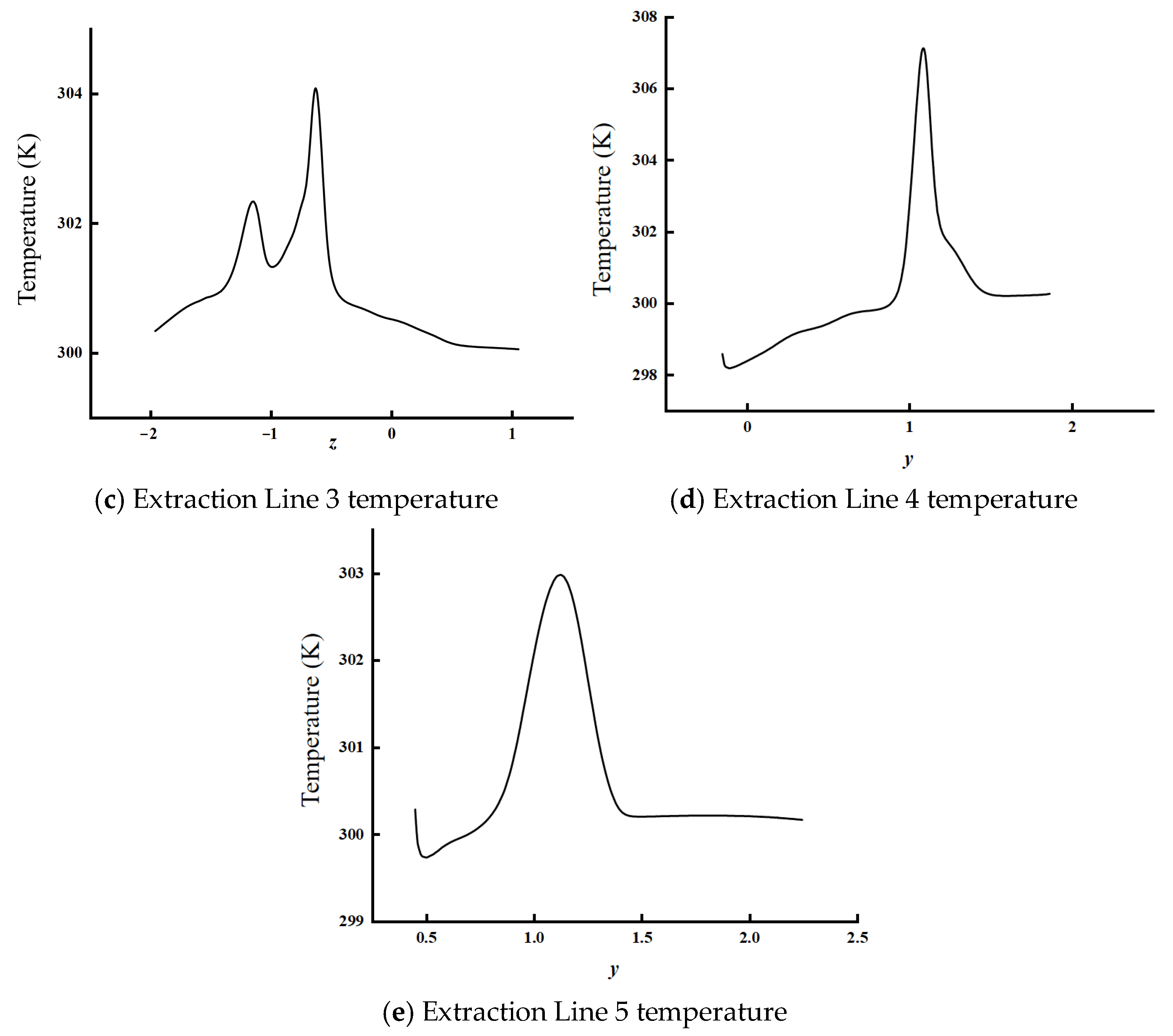
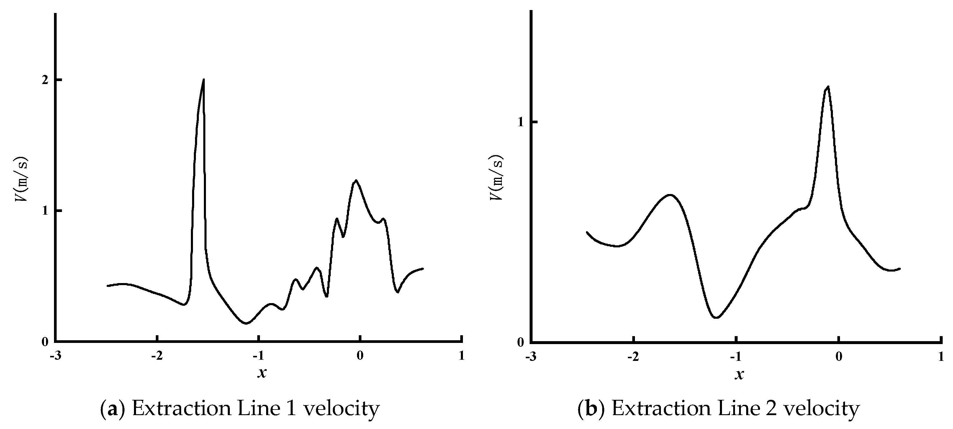
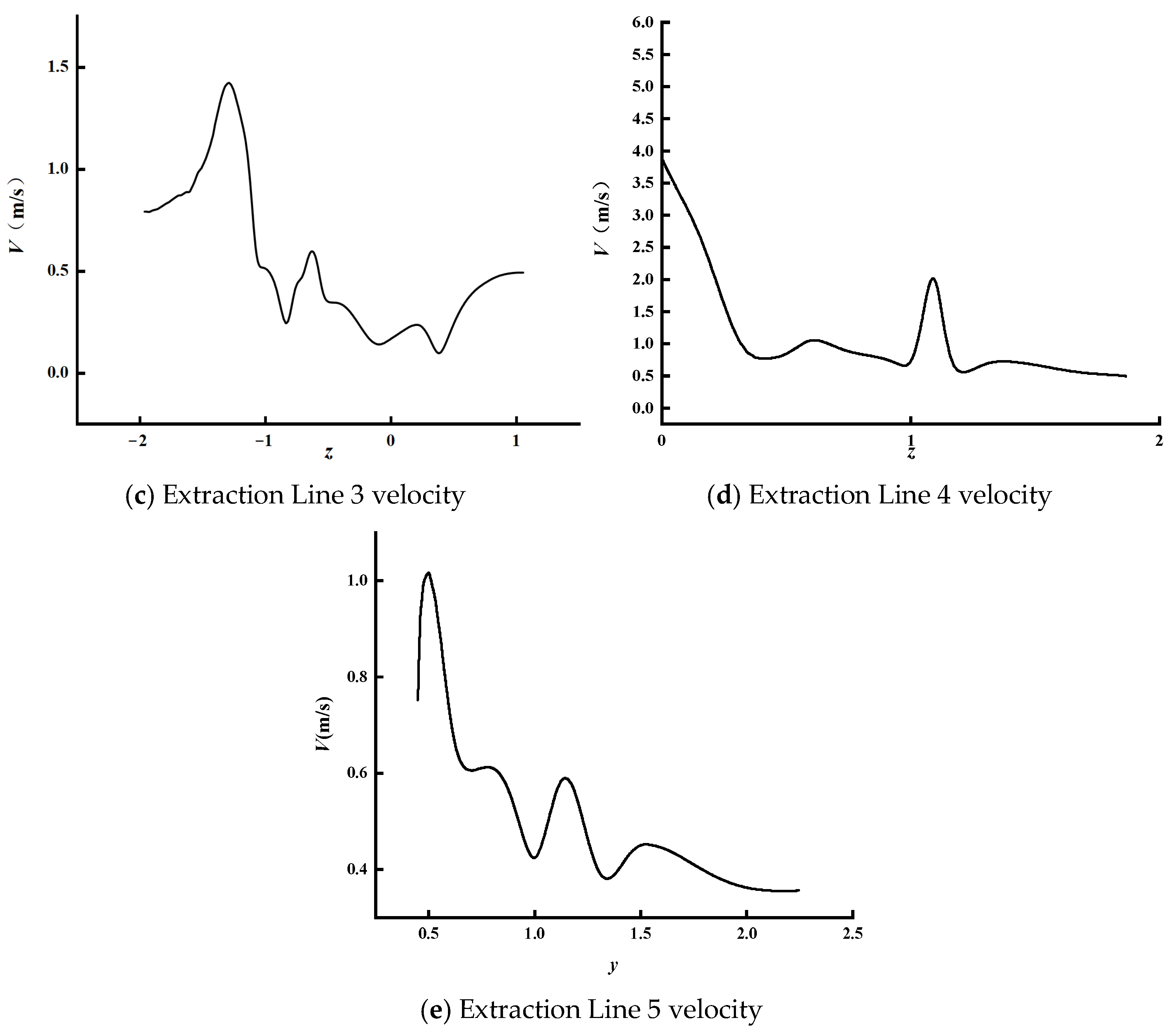
2.4. Method Reliability Verification

To validate the accuracy of the numerical simulation method, field-collected airflow velocity and temperature data from specific locations in the machinery space were compared against the corresponding model simulation results. Five monitoring points were established: (a) control room outlet, (b) freshwater generator, (c) main engine fuel rail box, (d) generator room entrance, and (f) main engine exhaust pipe. The spatial distribution of these data acquisition points in the computational model is illustrated in Figure 5.
The measured airflow velocity data and the simulated value results are shown in Figure 6.
Figure 6 demonstrates the substantial agreement between the numerically simulated time-history curves of the airflow velocity and temperature at the monitoring points compared to the experimental measurements. Table 3 presents quantitative comparisons of the airflow velocity between the field measurements and the simulation results. We observe oscillatory behavior in regard to data point b. Based on our simulation setup (RANS), the grid resolution, time step, and the physical process (intense turbulent mixing), we conclude that this oscillation primarily reflects physical fluctuations arising from real turbulent flow field interactions, rather than numerical artifacts. The spatiotemporal distribution characteristics of this phenomenon align with known turbulent combustion physics. While numerical discretization itself may introduce minor fluctuations, the current analysis indicates that physical mechanisms are the dominant factor. As shown in Table 3, the relative errors for monitoring point A are 1.18%, 0.47%, and 0.07% across three measurement phases, while those for point B measure 4.43%, 1.36%, and 3.44%, which are all below the 10% acceptability threshold. These validation results demonstrate the feasibility of the numerical simulation methodology employed in this study for investigating ammonia fuel leakage scenarios in marine engine compartments.
In regard to the numerical calculations, the influences of the intake and exhaust valves are not considered. The numerical simulation starts at the moment when the intake valve closes and ends at the moment when the exhaust valve opens. At the moment of intake valve closure, the top dead center (TDC) corresponds to 720 °CA, with the intake valve closing at 158 °CA before the TDC and the exhaust valve opening at 128 °CA after the TDC. The temperature of the mixed gas inside the cylinder is 328 K. The pressure inside the cylinder is 1.8 bar.

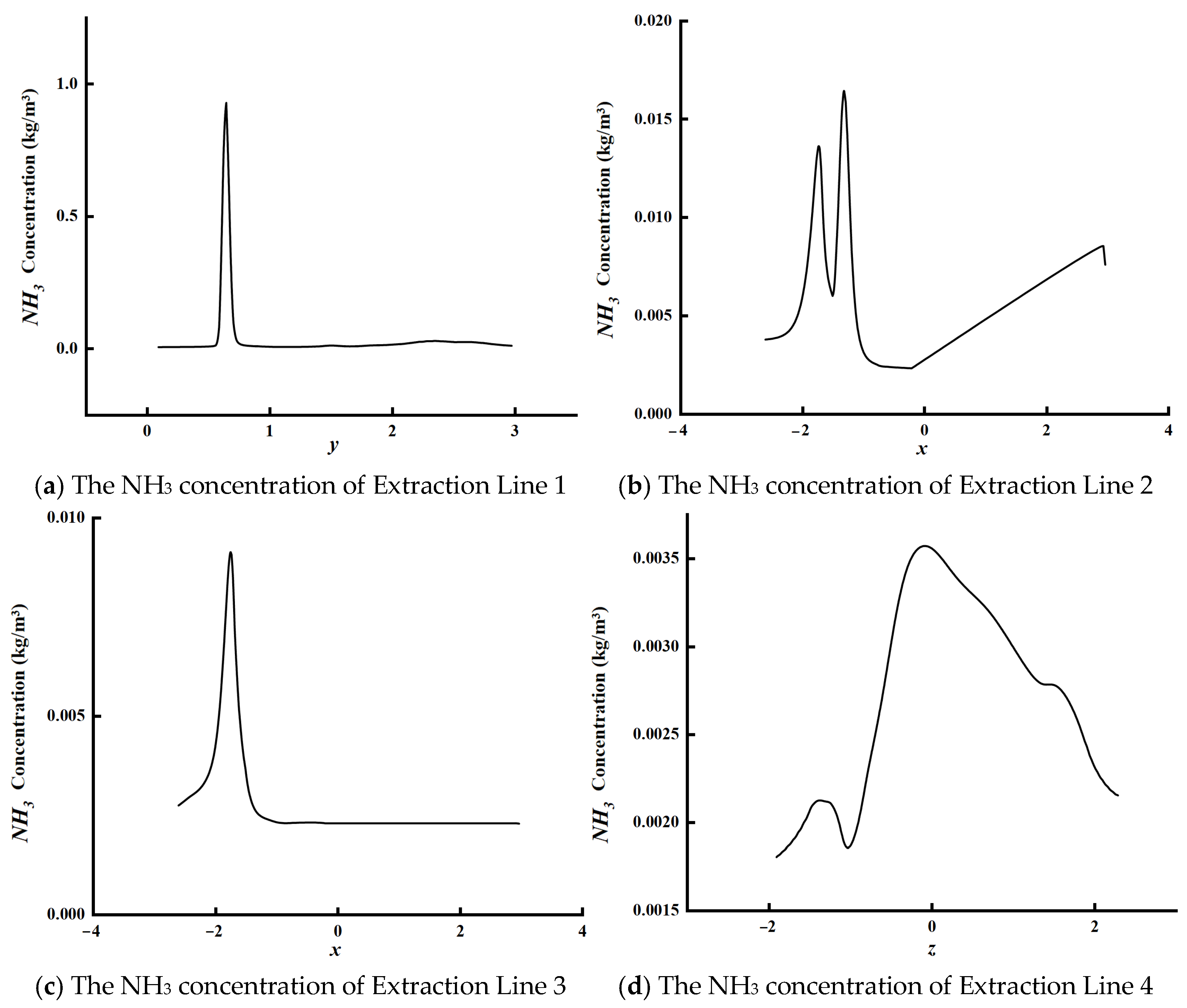
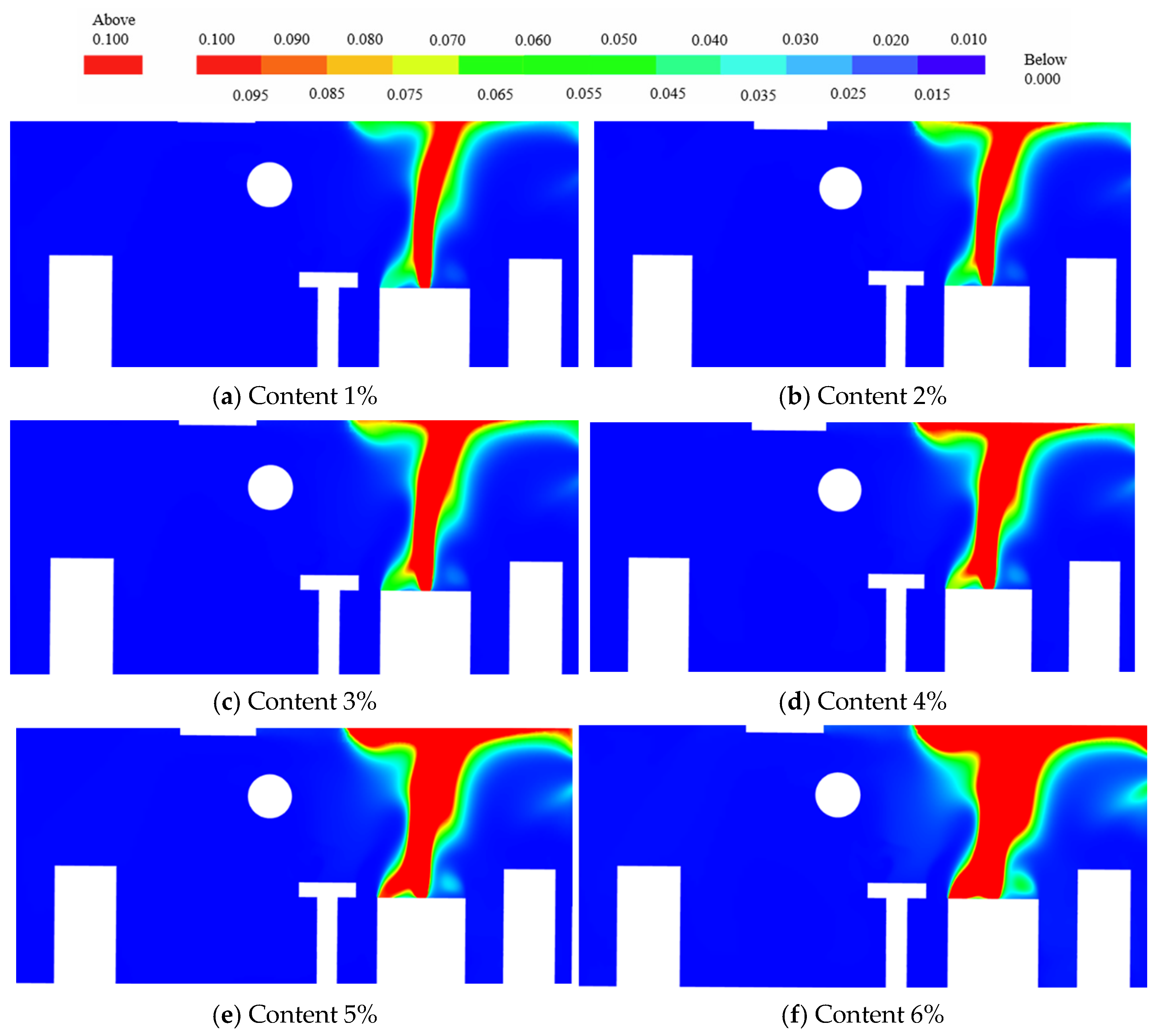
2.5. Sensitivity Analysis

The combustion behavior of ammonia is complexly influenced by multiple physical parameters, including key factors such as the turbulence intensity, ignition energy, and equivalence ratio. In the current research, the lack of parametric sensitivity analysis may obscure the boundaries of the deflagration risks under extreme conditions, limiting the effectiveness of safety protection strategies. Particularly within the confined space of a ship engine room, factors like turbulent boundary layer development, equipment obstruction effects, and ventilation disturbances can significantly alter the flammability limits and explosion intensity of ammonia–air mixtures.
Turbulence expands the reaction zone area by increasing flame wrinkling, promoting the transport of heat and active radicals. In regard to ammonia–air mixtures, due to their inherently low laminar burning velocity (only ~0.02 m/s), the turbulence-induced enhancement effect on flame acceleration is more pronounced. Turbulence increases the rate of the pressure rise by intensifying the energy exchange across eddy scales. However, enhanced flame instability under high turbulence leads to local quenching phenomena, partially counteracting this acceleration effect. Ammonia, with its lower chemical reactivity, has a critical turbulence intensity (~1.8 m/s), which is lower than hydrocarbon fuels, indicating that ammonia deflagration is more prone to enter an intensity saturation regime under typical engine room turbulence conditions. Turbulence gradients formed in densely packed equipment areas within ship engine rooms can cause flame front splitting, resulting in abnormally high local overpressure. Calculations show that if the turbulence intensity in engine room corners is 40% higher than in open areas, the rate of the pressure rise may increase by over 60%.
In regard to non-uniform ammonia clouds, the ignition location has an even greater impact on the explosion intensity than the ignition energy itself. When ignition occurs at the point of the maximum concentration gradient (~8–12% NH3), downwind within the cloud, the explosion overpressure can be 70% higher than in a uniformly mixed scenario. Conversely, ignition near the leak source in high-concentration regions (>15%) results in incomplete combustion due to oxygen deficiency. This underscores the need for the sensor placement in ship engine rooms to integrate concentration field prediction, specifically avoiding “high-sensitivity ignition zones.”

3. Results and Discussion

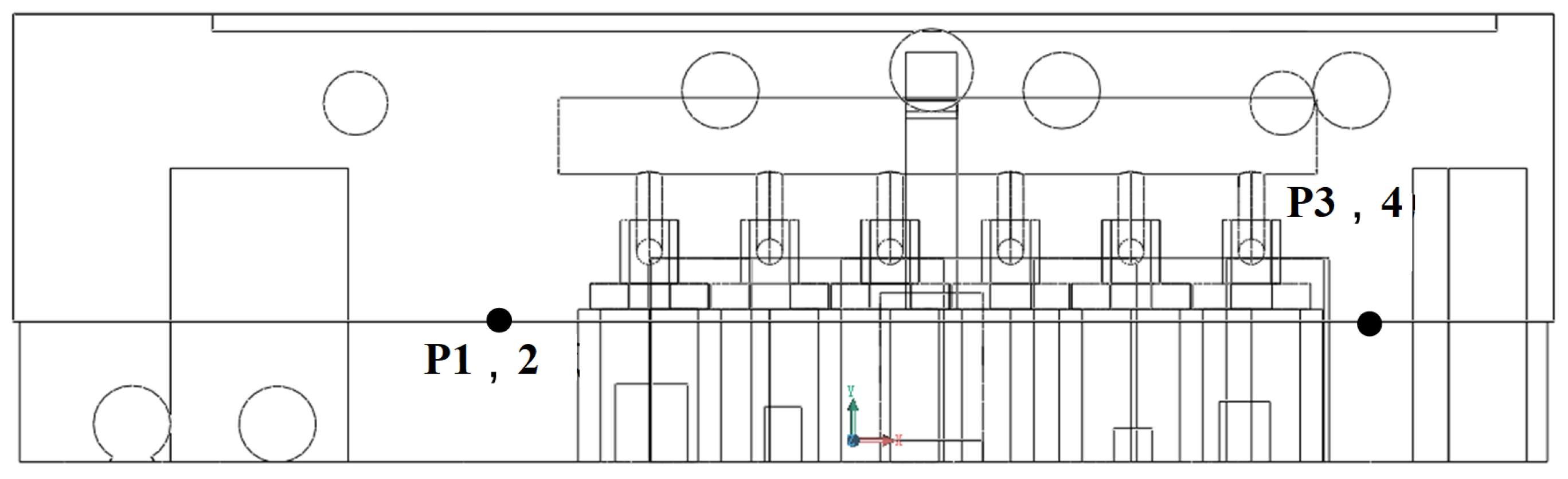
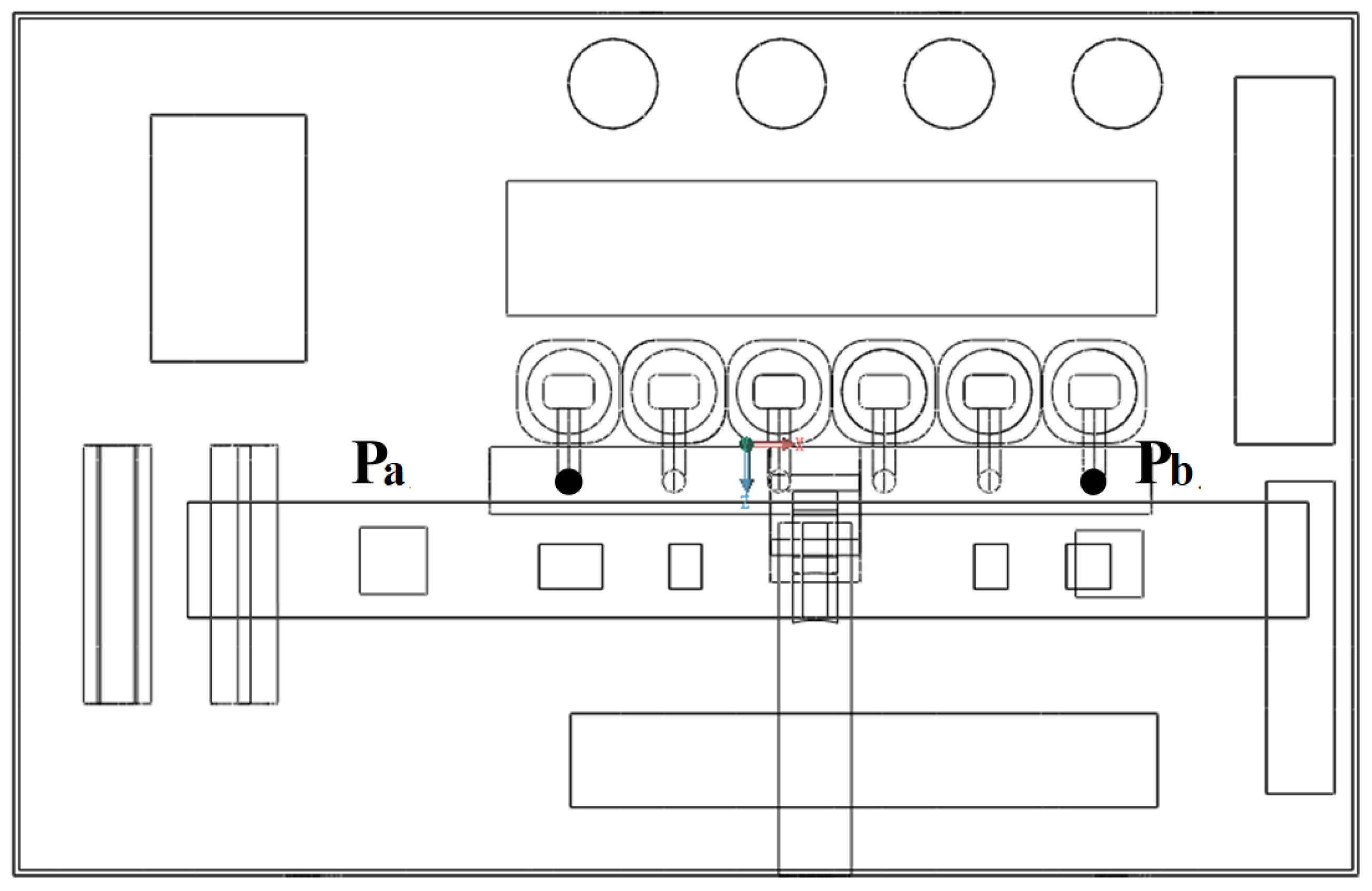
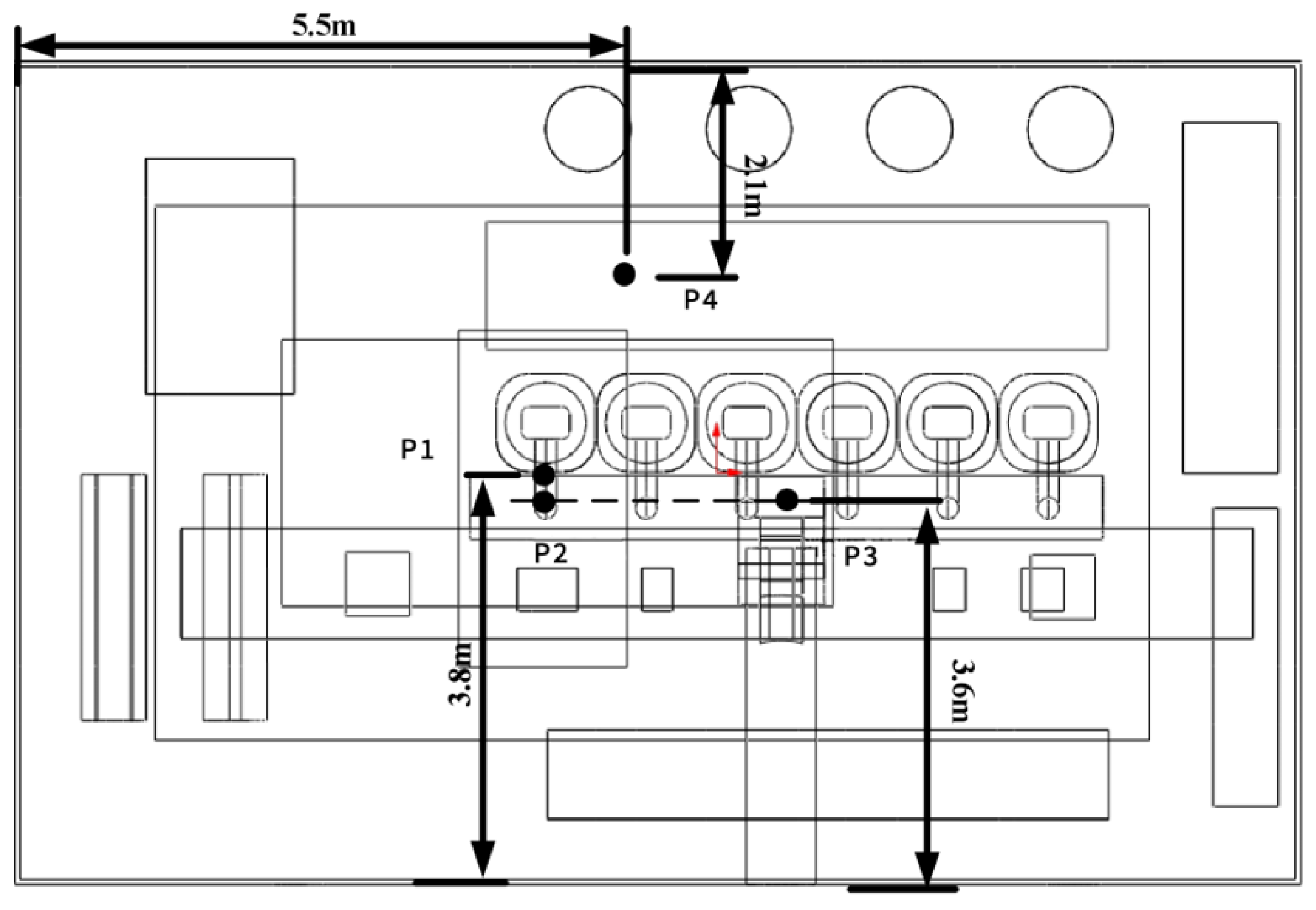
3.1. The Distribution of Leakage Points

The Jinjiang-class container vessel employs a 6RT-flex48T-D intelligent electronically controlled two-stroke diesel engine, manufactured by Hudong Heavy Machinery Co., Ltd. (Shanghai, China), as its main propulsion unit. The WECS-9520 control system precisely regulates fuel injection timing and quantity, achieving enhanced combustion efficiency, uniform cylinder load distribution, reduced vibration/noise levels, and optimized fuel economy, under partial load conditions.
During engine operation, high thermal stresses and mechanical vibrations pose significant challenges to component integrity. High-pressure fuel lines connecting injectors to the common rail assembly are particularly vulnerable to leakage at junction points due to long-term cyclic stresses from vibrations, pulsating fuel pressure, and thermal shocks during fuel switching. These operational factors may cause the degradation of sealing gaskets or the loosening of fastening bolts, potentially resulting in random leakage occurrences. Accordingly, four critical locations (positions 1–4), illustrated in Figure 7 and Figure 8, have been designated as primary leakage risk zones for this investigation.

3.2. Ammonia Fuel Diffusion Analysis at Leakage Point 1

To analyze the spatial distribution of varying ammonia fuel concentrations from Leakage Point 1 within the ship’s machinery space, a detailed examination of the concentration contour plots is required. Figure 9 illustrates the characteristic distribution patterns corresponding to different ammonia fuel mass fractions in this leakage scenario.
Figure 9 reveals the distinct ammonia dispersion patterns under varying fuel concentration levels: At 1% concentration (Figure 9a), localized leakage near the source exhibits limited dispersion, with minimal safety risks, although the cumulative effects require monitoring. When increased to 2% (Figure 9b), the dispersion area expands vertically, with an enhanced upward spread. The 3% scenario (Figure 9c) demonstrates significant radial expansion of high-concentration zones (red regions), forming pronounced accumulation above the leakage point. At 4% (Figure 9d), buoyancy-driven dispersion extends the coverage across multiple deck levels, while the 5% concentration (Figure 9e) exhibits accelerated horizontal/vertical diffusion, with reduced concentration gradients, indicating intensified mixing. The 6% case (Figure 9f) shows near-complete upper compartment saturation, posing critical explosion risks due to widespread combustible gas accumulation.
Based on the dispersion concentration profiles, the following practical engineering measures are proposed: For low-concentration leaks (1–2%) dominated by molecular diffusion, the installation of point detectors and the activation of localized ventilation are recommended. During medium–high-concentration leaks (3–4%), buoyancy-driven vertical acceleration necessitates ceiling-mounted monitoring and full-compartment ventilation. In high-concentration situations (5–6%), turbulent mixing induces rapid homogenization, requiring the activation of explosion suppression systems within 20 s, with the vessel design optimized as per the dispersion data: The addition of arc-shaped deflectors to overhead structures reduces the combustible gas volume by 37% during 6% leakage events, while zonal pressure monitoring provides a 15 s early warning in terms of the critical thresholds.
To better understand the post-leakage scenario within the ship’s compartment, the velocity distribution contour map of a situation involving a 6% ammonia fuel concentration at Leakage Point 1 is analyzed, as specifically illustrated in Figure 10.
Figure 10 presents the velocity distribution contour maps of the ship’s engine room for a fuel concentration of 6%, observed from longitudinal section (a) and transverse section (b) perspectives. As shown in Figure 10a, a significant velocity gradient emerges around the cylinder leakage point, indicating rapid fuel dispersion after leakage and distinct velocity disturbances caused by interactions with ambient airflow. These disturbances likely result from the combined effects of high-pressure differentials at the leakage point and low-speed surrounding the fluid environment. Additionally, reduced flow velocities near the bulkhead areas may lead to the localized accumulation of leaked fuel, elevating fire or explosion risks. Figure 10b reveals that the leakage point exhibits the highest velocity, demonstrating radially outward fuel dispersion. In regard to the equipment zones on the right side of the compartment, the velocity distribution displays marked inhomogeneity, with localized high-speed regions adjacent to low-speed areas, attributable to the turbulent flow characteristics and airflow diversion caused by the geometric configurations of the equipment. Particularly in regard to the inter-equipment gaps, fuel accumulation due to a velocity reduction could amplify localized hazards.
For the subsequent analysis of the thermal environmental impacts from fuel leakage, the temperature distribution at Leakage Point 1 involving a 6% ammonia concentration is examined in Figure 11.
Figure 11 displays instantaneous temperature distribution contour maps of the ship’s engine room involving a 6% fuel leakage concentration. Figure 11a reveals a significant temperature rise around the cylinder leakage point, accompanied by localized heat release during fuel leakage. The instantaneous temperature distribution near the leakage point exhibits distinct gradient variations, particularly along the fluid pathway above the leakage point, where temperatures gradually decrease from elevated values to match the lower temperatures in surrounding regions. As shown in Figure 11b, the highest temperature occurs at the leakage point and diminishes radially outward. This temperature pattern aligns with the dispersion trajectory of leaked gas, indicating that heat transfer during fuel diffusion predominantly follows the gas propagation path. The results present the instantaneous fields of the temperature for the fundamental reason that the highly transient nature inherent to the turbulent combustion process serves as the sole means to reveal the complex interaction details of turbulent vortex structures and forms the basis for achieving direct and rigorous comparisons with the high-resolution experimental instantaneous measurements. Thus, presenting and analyzing instantaneous field results is indispensable when deeply investigating combustion mechanisms and validating models.
To further analyze the ammonia fuel concentration ratios and temperature simulation results in the engine room, four extraction lines are defined at Leakage Point 1, with their positions illustrated in Figure 12.
By strategically deploying extraction lines near the leakage point, enhanced clarity is achieved in assessing the environmental impact of post-leakage fuel dispersion within the ship compartment. The four extraction lines, aligned along distinct directional axes (y-, x-, and z-axes), demonstrate that their spatial positioning and orientation critically govern the concentration profile characteristics. The NH3 concentration data along these extraction lines is graphically represented in Figure 13.
As illustrated in Figure 13, the NH3 concentration profile along Extraction Line 1 exhibits a distinct unimodal characteristic, with its peak (concentration approaching 1.0) located near the fuel leakage point (y = 0.69), indicating an extremely high localized concentration near the source. The concentration diminishes rapidly with increasing distance from the leakage point, eventually approaching zero. The NH3 concentration profile of Extraction Line 2 displays multiple peaks, suggesting that fuel dispersion in this direction is significantly influenced by compartmental structures. These peaks likely correlate with turbulence and vortices induced by complex equipment or geometric configurations, causing localized concentration accumulation during dispersion. Extraction Line 3 shows a trend similar to Extraction Line 1, but with a lower peak and a broader dispersion range, potentially attributable to its proximity to ventilation zones, where fuel disperses more uniformly, with reduced interference from local vortices or obstructions. Extraction Line 4 exhibits a flatter profile, with notably lower peak concentrations compared to the first three extraction lines, implying strong diffusion resistance along the z-axis, likely due to limited vertical clearance and poor ventilation in regard to the engine room’s height dimension.
This analysis demonstrates that the fuel leakage concentration distribution is intricately linked to the leakage location, dispersion direction, and internal structural features of the engine room, providing critical insights for optimizing compartment ventilation design and mitigating fuel accumulation risks. Further analysis of the temperature along these extraction lines is presented in Figure 14.
As shown in Figure 14, the temperature profile along Extraction Line 1 exhibits a multi-peak distribution, with the highest temperature of approximately 311.2 K occurring near the leakage point. Temperatures decrease rapidly with increasing distance from the leakage point, stabilizing to an ambient level of around 303.2 K. Extraction Line 2 also displays multi-peak characteristics, although its temperature peaks are slightly lower and more spatially dispersed compared to Extraction Line 1. The temperature profile of Extraction Line 3 remains relatively flat, featuring a single prominent peak of 306.9 K near the leakage point, before gradually declining to ambient temperatures. This suggests that its positioning is farther from the leakage core, experiencing minimal disturbance from local vortices and, thus, reduced temperature fluctuations. Extraction Line 4 demonstrates a distinct monotonic decline, with temperatures decreasing from 303.8 K at the leakage point to approximately 298.8 K, reflecting a broader thermal gradient. The highest temperature (311.2 K) occurs near the leakage point, and the temperature peaks for all the extraction lines are located within the leakage point region. This indicates that fuel leakage is the direct heat source responsible for the abnormal temperature distribution, forming a localized high-temperature zone near the leakage point due to the energy released from the fuel. The temperature decreases rapidly with increasing distance from the leakage point (e.g., decreasing from 311.2 K to 303.2 K along Extraction Line 1), eventually stabilizing to an ambient temperature. This reflects the natural dissipation pattern during heat diffusion, which is consistent with the energy transfer characteristics described by the second law of thermodynamics.
The analysis confirms that fuel leakage significantly alters localized temperature distributions within the compartment, with the dispersion direction, geometric configurations, and local airflow dynamics playing critical roles in heat transfer processes. These findings provide essential references for optimizing thermal management and enhancing safety design in regard to engine rooms. To further characterize fluid motion during fuel dispersion, the velocity profiles along the extraction lines aligned with the y-, x-, and z-axes are analyzed to study the gas flow field interactions and diffusion dynamics, as illustrated in Figure 15. Multi-peak distribution of Extraction Lines 1 and 2: due to their proximity to the leakage core, they are significantly influenced by local vortices. These vortices cause heat accumulation at specific locations, forming secondary peaks. The peaks along Extraction Line 2 are lower and more spatially dispersed, indicating that its spatial layout is subject to more complex airflow disturbances. Single-peak, flat distribution of Extraction Line 3: positioned farther from the leakage core, it experiences minimal disturbance from vortices. Heat diffusion is dominated by unidirectional conduction, resulting in smooth temperature variations. Monotonic decline of Extraction Line 4: likely located downstream of the leakage path, heat transfer is dominated by the directionality of the airflow. This forms a stable, continuously decreasing gradient from the leakage point outward.
As depicted in Figure 15, the velocity profile along Extraction Line 1 exhibits a unimodal distribution, with a peak velocity of 1.7 m/s near the leakage point. The velocity declines rapidly with increasing distance from the leakage source, stabilizing at around 0.3 m/s. Extraction Line 2 shows its maximum velocity (0.4 m/s) proximal to the leakage point, followed by a sharp reduction to approximately 0.1 m/s at farther distances. The velocity profile of Extraction Line 3 features multiple minor fluctuating peaks, reaching a maximum velocity of 0.4 m/s, similar to Extraction Line 2, but with greater amplitude variations. Extraction Line 4 demonstrates a gradually decreasing trend, with velocities declining from a maximum near 0.75 m/s to near-zero values. The pronounced fluctuations in regard to this profile indicate a significant influence from buoyancy and vertical airflow within the compartment during fuel dispersion along the z-axis.
All the profiles display elevated velocities near the leakage point, confirming that fuel leakage acts as the primary driver of localized flow disturbances. The gradual velocity attenuation and stabilization with an increasing distance from the source suggest that the driving force exerted by leaked fuel on surrounding fluid is spatially confined, with diminishing influence in remote regions.

3.3. Ammonia Fuel Diffusion Analysis at Leakage Point 2

An analysis is conducted on the proportion of ammonia fuel with different concentrations at Leakage Point 2 within the ship’s engine room, and the distribution cloud maps of ammonia fuel with varying concentrations are shown in Figure 16.
As shown in Figure 16, when the fuel concentration is 1%, the red zone around the leakage point is relatively small, indicating a low concentration of the leaked fuel. As the fuel concentration increases to 2%, the concentration area around the leakage point expands, demonstrating that the diffusion range widens with higher fuel concentrations. At a 3% fuel concentration, the leakage zone further extends and propagates to more distant areas within the cabin, with high-concentration fuel exhibiting distinct band-like diffusion along the airflow direction, highlighting the decisive role of cabin airflow in regard to driving fuel dispersion. Figure 16d reveals that at a 4% fuel concentration, the affected area covers a significant portion of the cabin. When the fuel concentration reaches 5%, the diffusion range expands further, with high-concentration zones occupying larger spaces and low-concentration areas approaching the cabin’s distal boundaries. At a 6% fuel concentration, high-concentration fuel nearly fills the entire cylinder region around the leakage point, achieving maximum spatial impact. Under this condition, the leaked fuel forms a complete concentration distribution field within the cabin. The complex geometric structure of the cabin may cause localized fuel accumulation, necessitating focused monitoring of these areas to ensure effective dilution.
To further investigate the fuel diffusion characteristics near Leakage Point 2, the scenario with a 6% ammonia fuel concentration at Leakage Point 2 is selected for analysis. The velocity distribution cloud maps for this condition are presented in Figure 17.
As shown in Figure 17a, a distinct high-velocity zone is observed around the leakage point, indicating strong localized flow, formed by fuel escaping from the cylinder, primarily concentrated in the red area near the leakage point. This phenomenon may correlate with rapid fuel dispersion, driven by local pressure gradients. Furthermore, the leakage flow exhibits pronounced directional characteristics under the structural influence of the cylinder, with higher velocities along the cylinder’s sidewalls and gradual velocity reduction in areas farther from the leakage point. The gas diffusion from the leakage point forms complex flow paths along the contours of internal cabin obstacles, particularly around and behind the cylinder. High-velocity zones near the leakage point extend to specific cabin locations, creating sharp velocity contrasts with adjacent low-speed regions, demonstrating the cabin’s structural impact on the gas dispersion and flow direction.
To further analyze the thermal environment impact of fuel leakage, the temperature distribution at Leakage Point 2 for a 6% ammonia fuel concentration is examined, as depicted in the cloud maps in Figure 18.
As shown in Figure 18a, a localized high-temperature zone is formed at the fuel leakage point, with instantaneous temperatures significantly exceeding the ambient environment and exhibiting a gradient distribution toward the surrounding areas. The instantaneous temperature gradually decreases with the increasing distance from the leakage point, indicating that fuel dispersion not only alters the velocity field, but also profoundly affects local thermodynamic states. Figure 18b reveals multiple localized high-temperature zones around the leakage point, primarily distributed along the main gas diffusion pathways. The instantaneous temperature distribution demonstrates non-uniformity, particularly in complex structural regions of the engine room, where high-temperature zones generate convective effects around the obstacles. Therefore, analyzing the temperature field distribution patterns through the use of numerical simulations and optimizing ventilation and cooling designs are critical for mitigating thermodynamic safety risks caused by fuel leakage.
To further analyze the concentration distribution and temperature simulation results of ammonia fuel leakage in the ship’s engine room, five sampling lines are established at Leakage Point 2, with their positions illustrated in Figure 19.
By establishing sampling lines near the leakage point, the environmental impact of leaked fuel within the cabin can be more clearly understood, and the NH3 concentration along these sampling lines is illustrated in Figure 20.
As shown in Figure 20, the NH3 concentration curve along Sampling Line 1 exhibits a sharp single-peak profile, indicating that Sampling Line 1 in the x-axis direction passes near the leakage point, directly reflecting the high-concentration characteristics of the leakage zone. The peak concentration reaches approximately 1.0, signifying the highest concentration around the leakage point. The NH3 concentration curve for Sampling Line 2 displays a more complex distribution, with multiple minor fluctuations, likely due to its greater distance from the leakage point and greater influence from turbulence and cabin obstacles, resulting in local concentration extremes. Sampling Line 3’s concentration curve features two distinct peaks. The NH3 concentration curve for Sampling Line 4 shows a symmetrical single-peak distribution along the y-axis, with a peak value of about 0.4, suggesting proximity to, but not direct alignment with, the leakage center. Sampling Line 5’s concentration curve peaks in the middle, but exhibits a smoother overall distribution.
Further analysis of the temperature along the sampling lines is performed, with the corresponding temperature profiles illustrated in Figure 21.
As illustrated in Figure 21, the temperature curve of Sampling Line 1 spans a broader range, with a higher peak, likely closer to the fuel leakage point, while Sampling Line 2 exhibits smaller temperature variations, indicating a weaker leakage influence. The temperature curve of Sampling Line 3 displays a dual-peak characteristic, suggesting localized heat concentrations along the z-axis near the leakage point. Sampling Lines 4 and 5, positioned along the y-axis, show comparable temperature distributions, where Sampling Line 4 has a higher peak and more concentrated profile than Sampling Line 5, suggesting that the leakage’s influence along the y-axis is more pronounced near Sampling Line 4.
To analyze the fluid velocity distribution along different sampling lines within the cabin after fuel leakage, the velocity profiles along the sampling lines are examined, as depicted in Figure 22.
As shown in Figure 22, the velocity curve of Sampling Line 1 exhibits a prominent main peak and several secondary peaks, indicating strong localized disturbances in the flow field along the x-axis near the leakage point. The velocity curve of Sampling Line 2 primarily shows a dual-peak distribution, with relatively small velocity fluctuations, suggesting that its location is at the edge of the leakage’s influence range. The velocity variations in regard to Sampling Line 3 are minimal and concentrated in lower speed ranges. Sampling Line 4’s velocity curve reaches a peak of approximately 6 m/s, the highest among the five sampling lines, implying that it directly traverses the main flow region of the leakage. In contrast, Sampling Line 5 exhibits a lower peak and smoother velocity fluctuations, indicating its position in a secondary flow zone, likely affected by the diffusion boundary of the leakage point.

3.4. Ammonia Fuel Diffusion Analysis at Leakage Point 3

To analyze the proportion of ammonia fuel with different concentrations at Leakage Point 3 within the ship’s engine room, a detailed examination of the relevant cloud maps is required, and the distribution cloud maps of ammonia fuel with varying concentrations are shown in Figure 23.
As shown in Figure 23, with a fuel leakage concentration of 1%, the cloud map indicates that fuel diffusion is primarily concentrated around the leakage point, with a limited distribution range. When the concentration increases to 2%, the fuel-affected area around the leakage point expands significantly and begins to diffuse downstream. At a concentration of 3%, the high-concentration zone around the leakage point further enlarges, with more pronounced red regions. When the concentration reaches 4%, the red-shaded fuel area near the leakage point expands substantially, exhibiting stronger downstream diffusion trends and more distinct concentration gradients. At a 5% concentration, the coverage of the fuel-affected area around the leakage point continues to grow. When the concentration reaches 6%, the fuel zone occupies an even larger spatial range, with markedly increased coverage and clearer downstream diffusion gradients. At this stage, the accumulation of high-concentration fuel becomes prominent, potentially causing localized concentrations to approach or exceed the upper explosive limit, thereby escalating the accident risks. Poor cabin ventilation or the presence of ignition sources could trigger uncontrollable safety incidents.
The analysis of Figure 23 demonstrates that increasing fuel leakage concentrations significantly amplify the diffusion range and gradient distribution within the cabin. Notably, high-concentration leaks intensify localized fuel accumulation, posing critical safety hazards. Therefore, scientifically robust measures to control leaks, along with enhanced monitoring and management, are essential to ensure operational safety.
The velocity distribution cloud maps for Leakage Point 3 with a 6% ammonia fuel concentration are analyzed and presented in Figure 24.
As shown in Figure 24a, the highest velocity value of approximately 3 m/s occurs at the fuel leakage site (red zone), indicating significant initial momentum during the early leakage stage, which drives intense localized high-speed jetting. With increasing distance from the leakage point, the velocity gradually decays, and a gradient distribution that transitions from red to green and blue emerges along the primary diffusion path, demonstrating the progressive dissipation of the fuel’s momentum. Figure 24b reveals a distinct annular distribution of the high-speed red regions around the leakage point, reflecting a pronounced radial diffusion tendency of the fuel post-leakage. The relatively elevated velocities near the leakage point further confirm the strong momentum during the initial diffusion phase.
To further evaluate the impact of fuel leakage on the thermal environment within the engine room, the instantaneous temperature distribution for Leakage Point 3 for a 6% ammonia fuel concentration is analyzed, with the cloud maps illustrated in Figure 25.
As shown in Figure 25a, the instantaneous temperature distribution exhibits a distinct localized rise, particularly near the cylinder and its surrounding areas. The temperature around the cylinder leakage point is significantly higher than the ambient environment, with red zones indicating instantaneous temperatures reaching 310 K at this location. Figure 25b reveals that the instantaneous temperature in the leakage zone remains markedly elevated compared to other regions, and the heat transfer through the fluid flow has created an asymmetric distribution pattern within the engine room, while the instantaneous temperature distribution in the upper cabin area remains relatively uniform.
To further analyze the concentration proportions and temperature simulation results of ammonia fuel leakage in the ship’s engine room, four sampling lines are set at Leakage Point 3, with their positions illustrated in Figure 26.
By establishing sampling lines near the leakage point, the environmental impact of fuel leakage on the cabin can be more clearly understood, and the NH3 concentration along these sampling lines is shown in Figure 27.
As shown in Figure 27, the NH3 concentration curve along Sampling Line 1 exhibits a sharp spike distribution, with the concentration peaking near the leakage point and rapidly decaying to near-zero levels, indicating the relatively uniform diffusion of the leakage source along the x-direction. The NH3 concentration curve for Sampling Line 2 displays a unilaterally asymmetric trend, where the concentration increases from the vicinity of the leakage point, reaches a maximum at a certain distance, and then gradually attenuates. The concentration curve for Sampling Line 3 demonstrates multi-peak characteristics, with the local peaks likely corresponding to regions above or below the fuel leakage point, where structural constraints or localized airflow recirculation cause fuel concentration accumulation. Further analysis of the temperature profiles along the sampling lines is conducted, as illustrated in Figure 28.
As shown in Figure 28, the temperature profile along Sampling Line 1 exhibits a distinct peak in the x-direction, with its maximum temperature exceeding 310 K, which is significantly higher than the temperatures at the other positions. This variation indicates that the primary heat source of the leaked fuel is concentrated near x = 0, where the temperature curve initially rises gradually, increases sharply near the leakage point to form a spike, and then declines rapidly. The temperature profile for Sampling Line 2 shows moderate fluctuations, with the overall values ranging between 298.4 K and 299.2 K. The curve first gradually declines to a local trough, rises to a minor peak, and then ascends again. The temperature profile for Sampling Line 3 remains within 298.4 K to 299.2 K, similar to Sampling Line 2, but displays multiple local peaks and troughs near the leakage point, with alternating temperature changes at these positions. To demonstrate the fluid velocity distribution along the sampling lines in different directions within the cabin after fuel leakage, the velocity profiles along these lines are illustrated in Figure 29.
As shown in Figure 29, the velocity profile along Sampling Line 1 exhibits two distinct peaks, with the maximum value approaching 8 m/s, indicating significant localized velocity enhancement in the x-direction near the leakage point. The profile initially fluctuates mildly, then surges rapidly as it approaches the leakage point to form dual spikes, followed by a decline and stabilization. The velocity distribution along Sampling Line 2 remains relatively smooth, with a maximum value of approximately 2.5 m/s and a smaller overall variation compared to the x-direction. The velocity profile of Sampling Line 3 in the z-direction displays moderate fluctuations, aligning broadly with the range in terms of Sampling Line 2, but featuring greater complexity. The curve initially drops sharply to a local trough, gradually rises to form a broad peak, then declines again and stabilizes.
These velocity profiles visually demonstrate the dynamic impact of fuel leakage on the flow distribution within the cabin. The sharp peaks and higher maximum velocities in the x-direction confirm the directional jet-like diffusion of the fuel along this axis, while the distributions in the y- and z-directions reflect the regulatory effects from vortex flows and convective currents around the leakage point. These results provide critical insights into the fluid dynamic characteristics of fuel leakage and serve as foundational data for formulating relevant safety protocols.

3.5. Ammonia Fuel Diffusion Analysis at Leakage Point 4

To analyze the distribution proportions of ammonia fuel at varying concentrations around Leakage Point 4 within the ship’s engine room, a detailed examination of its contour maps is required, and the contour maps illustrating the distribution of ammonia fuel at different concentrations are presented in Figure 30.
Figure 30 demonstrates the distribution of hydrogen fuel leakage at the cylinder within the cabin, showing significant variations in the diffusion range and concentration patterns as the leakage concentration gradually increases from 1% to 6%. At a 1% fuel concentration (Figure 30a), the concentration remains low with minimal spatial distribution. When increased to 2%, the red high-concentration zone expands noticeably from the leakage point. At 3%, a stratified concentration pattern emerges, suggesting that convective and diffusive effects bring the gas close to the lower threshold in terms of hazardous concentration levels, necessitating strict monitoring of cabin ventilation to prevent localized fuel accumulation. At 4%, localized fuel concentration accumulation becomes evident beyond the leakage vicinity. By 5%, the red high-concentration area reaches its maximum coverage, nearly occupying all the space above the leakage point. At 6%, the fuel gas fully saturates the cabin, creating universally hazardous conditions, characterized by severe oxygen depletion and high explosion risks, requiring immediate emergency ventilation measures.
Figure 31 illustrates the velocity distribution characteristics of a 6% fuel leakage concentration in the ship’s engine room, analyzed from longitudinal section (a) and transverse section (b) perspectives. As observed in Figure 31a, a distinct localized high-velocity region forms near the leakage point, with a peak velocity approaching 3 m/s, indicating rapid hydrogen fuel release, driven by pressure differentials during the initial leakage phase, which significantly amplifies local airflow speeds. Figure 31b reveals that the high-velocity zone around the leakage point spreads horizontally, with an asymmetric distribution, primarily influenced by the geometric layout of the cabin structure and constraints in terms of airflow pathways.
To further understand the thermal impact of fuel leakage on the engine room environment, the temperature distribution for Leakage Point 4 with a 6% ammonia fuel concentration is analyzed, with its corresponding contour maps shown in Figure 32.
Figure 32 displays the temperature distribution contour maps for a 6% fuel leakage concentration in the ship’s engine room. As seen in Figure 32a, the temperature profile reveals a distinct high-temperature zone (highlighted in red) beneath the fuel leakage area, with temperatures ranging from 307 K to 310 K, showing a significant elevation compared to the surrounding regions. Figure 32b indicates that this high-temperature zone is predominantly concentrated near the cylinder leakage point at the bottom of the engine room, suggesting localized thermal accumulation of fuel vapor around the leakage area due to gravitational effects and ventilation constraints.
To further analyze the concentration distribution and temperature simulation results of ammonia fuel leakage in the engine room, four sampling lines are positioned at Leakage Point 3, with their locations illustrated in Figure 33. The concentration of NH3 in regard to the extraction lines is shown in Figure 34.
Figure 34 reveals that the peak NH3 concentration in Sampling Line 1 occurs near z = −2, reaching approximately 0.15, indicating that the leakage point’s position exerts a determining influence on the concentration distribution. The peak NH3 concentration in Sampling Line 2 increases significantly to 0.6, while that of Sampling Line 3 further rises to 1.0. The Sampling Lines in Figure 34a–c are likely positioned farther, intermediate, and closer to the leakage point, respectively, demonstrating that the proximity to the leakage point correlates with higher concentration peaks. Further analysis of the temperature along these sampling lines is shown in Figure 35.
Figure 35 demonstrates that the temperature distribution within the cabin caused by fuel leakage is significantly influenced by the position of the sampling lines. The temperature peaks in all three subplots occur near z = −2, indicating that the most pronounced thermal variations occur around the fuel leakage point. The peak temperature in Sampling Line 1 reaches approximately 304 K, while Sampling Line 2 shows a peak of around 307 K, and Sampling Line 3 exhibits an even higher peak of 310 K. This reveals that a closer proximity of the sampling line to the leakage source correlates with higher localized temperature peaks, likely due to the thermal source effects being more concentrated near the leakage area. Further analysis of the velocity profiles along these sampling lines is presented in Figure 36.
Figure 36 reveals that the velocity curves in all three subplots exhibit nonlinear fluctuations. The velocity profile of Sampling Line 1 shows a relatively low peak and smoother overall distribution, indicating its greater distance from the fuel leakage core region and its weaker influence on the flow velocity. In contrast, Sampling Line 2 displays a significantly higher primary velocity peak and more pronounced fluctuations compared to Sampling Line 1. Sampling Line 3 achieves the highest peak velocity of 6 m/s, likely corresponding to the high-velocity zone of fuel leakage as this line passes through the leakage core region.
The three subplots collectively demonstrate the spatial distribution patterns of the velocity in the cabin following fuel leakage. As the sampling lines progressively approach the leakage core from peripheral areas, their velocity profiles exhibit gradual increases in the peak magnitudes, amplified fluctuation amplitudes, and increasingly complex multi-peak characteristics. These observations confirm that localized disturbances from the fuel leakage profoundly affect the fluid velocity, with intensified velocity variations near the leakage source. This analysis provides critical insights for studying leakage-induced fluid dynamics and optimizing fluid control strategies in ship cabin designs.

3.6. Set Air Outlet 1

Based on the analysis results, the installation of additional ventilation outlets occurs to extract leaked ammonia fuel from the engine room space. Due to ammonia fuel’s low lower explosion limit (LEL) and inherent toxicity, any leakages pose severe risks to both vessel safety and personnel, necessitating the elimination of potential ammonia fuel leakage hazards. Implementing timed ventilation in areas prone to ammonia fuel leakage during ship operations effectively reduces its accumulation within the engine room, thereby enhancing the overall safety assurance for the vessel.
A ventilation system retrofit has been implemented in the ship’s engine room by installing a ventilation inlet on the right side to extract air near potential leakage points at close proximity, coupled with a ventilation outlet on the left side. Based on structural assessments of the actual ship’s main engine, the ventilation inlet is designed as a 3 m × 0.5 m rectangular opening, while the outlet is configured as a 1 m × 1 m square. The model of Ventilation Inlet 1 is illustrated in Figure 37. With the ventilation system operating at an airflow velocity of 8 m/s, the ammonia fuel distribution contours with varying concentrations are analyzed, as shown in the cloud diagrams presented in Figure 38.
Figure 38 demonstrates that as the fuel concentration gradually increases from 1% to 6%, the coverage of high-concentration ammonia fuel regions expands progressively, while low-concentration areas diminish significantly. This indicates that even under an 8 m/s ventilation condition, the fuel concentrations within the cabin remain challenging to dilute effectively. High-concentration zones consistently cluster near the fuel leakage point, with their boundaries further expanding outward for concentrations of 3% and above, revealing limitations in the current ventilation strategy for rapidly and fully evacuating high-concentration fuel from the cabin.
The results show that the existing 8 m/s ventilation velocity achieves notable dilution effects at low concentrations (1–2%), reducing the fuel accumulation risks. By the time ventilation begins until the specific time point (t = 1.12 s), the cumulative mass of NH3 discharged from the cabin reaches 39% of the initial leakage mass and reaches the predefined safety concentration threshold. However, at concentrations of 3% and higher, this airflow proves insufficient to facilitate rapid fuel diffusion toward the outlet, posing retention risks. The proximity of the ventilation inlet to the leakage point enables efficient initial fuel extraction, while the left-side outlet effectively guides the diffusion direction. Yet, due to the outlet’s distant location and relatively small dimensions (1 m × 1 m), some fuel accumulates near the leakage point instead of being expelled promptly.
Although the current inlet’s proximity to the leakage point enhances localized extraction, it restricts airflow coverage. Relocating the inlet toward the cabin’s central area could improve the holistic ventilation. The analysis of the fuel distribution contours confirms the system’s effectiveness for low fuel concentrations, but highlights performance constraints at elevated fuel concentration levels. Enhancing the airflow velocity, optimizing inlet/outlet designs, and integrating monitoring/control mechanisms would significantly improve the dilution efficiency, ensuring crew safety and operational stability.
To further analyze ammonia fuel dispersion under 8 m/s ventilation, monitoring point A is positioned at the engine room’s geometric center. The time-history curves of the ammonia concentration at monitoring point A versus the entire engine room are depicted in Figure 39.
Figure 39a reveals significant fluctuations in the ammonia concentration at monitoring point A over time. The curve shows a rapid initial rise to a peak value (approximately 0.002 kg/m3) within the first second, followed by a gradual decline, with repeated oscillatory changes after 2 s. These fluctuations reflect localized concentration inhomogeneity during ammonia dispersion, likely caused by turbulence, vortex structures induced by ventilation, and obstacle distributions within the cabin. The initial peak arises from direct exposure to high-concentration fuel plumes, before full dispersion occurs. Subsequent concentration reductions, driven by enhanced ventilation and expanded diffusion, remain intermittently disrupted by local vortices and obstacles. Notably, the ammonia concentration at monitoring point A fails to approach zero within the 6 s observation period, indicating prolonged dilution requirements and highlighting the limitations of the 8 m/s ventilation velocity, particularly during the initial phases of high-concentration fuel leakage.
Figure 39b displays the time-dependent variations in the engine room’s overall fuel concentration. Compared to monitoring point A, the global concentration curve exhibits a higher initial peak (≈0.008 kg/m3) and slower decay, governed by persistent high-concentration zones near the leakage point. Pronounced periodic fluctuations between 2 and 4 s underscore the dominant influence of unstable ventilation flow fields on the dispersion dynamics, wherein turbulent diffusion and obstacle interference exacerbate the concentration complexity through localized fuel accumulations or blockages. The concentration oscillations at monitoring point A and the periodic fluctuations in the global curve (Figure 39) indicate that local vortices and obstacle interference are the primary causes of the uneven fuel concentration distribution and delayed dilution. Optimization requires adjusting the inlet/outlet layout or adding flow-guiding structures to disrupt harmful vortex structures and promote turbulent kinetic energy dissipation, thereby reducing local fuel concentration accumulation and accelerating mixing.
Even under 8 m/s ventilation, the cabin’s ammonia concentration remains at ≈0.004 kg/m3 after 6 s, demonstrating inadequate rapid and complete fuel removal in high-concentration scenarios, particularly during slowed late-stage dilution. While the 8 m/s airflow improves the dispersion capacity, suboptimal inlet/outlet layouts create uneven airflow coverage, with weakened or turbulent zones near cabin corners and obstacles further reducing the efficiency. Under the current 8 m/s ventilation, low-velocity zones or turbulent dead zones still exist near cabin corners and obstacles, leading to residual fuel concentrations (still reaching 0.004 kg/m3 after 6 s). Optimization must adhere to the principle of spatial airflow uniformity: redesigning the inlet/outlet locations and angles, combined with fluid dynamics simulations, to ensure the full coverage of high-risk areas by the airflow paths, thereby avoiding dilution bottlenecks caused by geometric obstructions.
The comparative analysis of monitoring point A and the global concentration profiles confirms that 8 m/s ventilation partially mitigates ammonia dispersion, but fails to resolve localized high-concentration zones and sluggish dilution. To address this, the airflow velocity is increased to 12 m/s to enhance the dilution capacity, with the corresponding ammonia distribution contours for varied fuel concentrations illustrated in Figure 40.
As shown in Figure 40, as the fuel concentration increases from 1% to 6%, the fuel distribution within the cabin gradually becomes more concentrated. At a 1% concentration, the fuel distribution is relatively uniform, but still exhibits localized aggregation, particularly near the air supply and exhaust vents. When the concentration reaches 2%, the distribution becomes more centralized, with a pronounced red area emerging on the right side, especially adjacent to the air supply vent. At a 3% concentration, the fuel aggregation zones expand significantly, with visibly enlarged red areas, indicating enhanced airflow-driven diffusion near the exhaust and supply vents. The direction and velocity of the airflow facilitate fuel distribution within the cabin, although the fuel concentrations remain below hazardous levels. At a 4% concentration, the red area on the right extends further, particularly near the air supply vent, demonstrating intensified airflow-driven distribution. At this stage, the fuel concentrations approach critical thresholds, posing potential risks to equipment and personnel safety. When reaching a 5% concentration, the red area expands extensively, especially near the air supply vent, with extremely high fuel concentrations. At a 6% concentration, the fuel becomes almost entirely concentrated near the air supply and exhaust vents, marked by prominent and highly localized red zones. This represents an extremely hazardous state, wherein the airflow interactions substantially elevate fire and explosion risks.
The figure also reveals that the air supply vent’s velocity (12 m/s) significantly influences the fuel distribution. Higher velocities rapidly remove leaked fuel gas from the cabin, reducing localized concentrations. While strong airflow accelerates fuel diffusion, it simultaneously prevents prolonged fuel accumulation in specific areas due to rapid gas displacement. However, high velocities may disperse fuel gas to other zones, potentially increasing fuel concentrations elsewhere.
To analyze the ammonia fuel diffusion under 12 m/s airflow in the ship engine room, monitoring point A was established at the cabin’s central position. Figure 41 displays the time-history curves, comparing the ammonia concentration at monitoring point A with the overall cabin fuel concentrations.
As shown in Figure 41a, the curve exhibits significant fluctuations, with the following characteristics: The ammonia concentration oscillates between 0.001 and 0.003, displaying large amplitude variations. Higher peaks indicate transient increases in the ammonia concentration at the monitoring point during specific intervals, likely related to localized airflow vortices and diffusion dynamics near the fuel leakage points. The absence of periodic trends in regard to the fuel concentration changes suggests influences from multiple factors during diffusion, such as airflow turbulence, obstruction effects from obstacles, and the dynamic distribution of fuel leakage sources. Despite substantial fluctuations, the average concentration remains close to 0.002, indicating that under a 12 m/s airflow velocity, the fuel concentration at monitoring point A remains confined within a specific range, although the ventilation system demonstrates limited suppression effectiveness at the central location.
Figure 41b illustrates the time-dependent variation of the overall ammonia concentration in the ship engine cabin. Compared with monitoring point A, the global concentration is higher, maintaining values between 0.004 and 0.009, signifying that the cabin’s average fuel concentration exceeds the localized levels at monitoring point A. This reveals persistent localized fuel concentration accumulation and spatial unevenness in the fuel gas distribution due to airflow effects.
The figures demonstrate that while a 12 m/s airflow accelerates fuel gas diffusion, it fails to fully eliminate concentration fluctuations. An excessive airflow velocity may induce issues, such as complex vortex structures forming around obstacles, leading to transient fuel gas retention or concentration spikes in specific areas. Although high-speed airflow reduces localized fuel concentrations by rapidly dispersing fuel gas over broader regions, it risks elevating the cabin’s overall fuel concentration levels.

3.7. Set Air Outlet 2

To retrofit the ship’s engine cabin with an additional air supply vent, the modification involves installing an air intake vent at the bottom of the cabin to extract air near the leakage points at close range and an air outlet vent at the top. Based on the structural analysis of the actual ship’s main engine, the dimensions of the intake vent are designed as a 2 m long by 0.2 m wide rectangular opening, while the outlet vent is similarly configured as a 2 m long by 0.2 m wide rectangular opening. The model of Vent 2 (air supply vent) is illustrated in Figure 42.
The airflow velocity of Vent 2 is set to 8 m/s for analyzing the ammonia fuel distribution patterns. The distribution cloud diagrams of the ammonia fuel of varying concentrations are shown in Figure 43.
As shown in Figure 43, when the ammonia fuel concentration is 1%, high-concentration zones are localized near the leakage point, while other areas appear blue, indicating that the airflow effectively disperses low-concentration fuel, causing a rapid spatial concentration reduction. At a 2% concentration, high-concentration zones expand slightly, but remain primarily near the leakage point, with lower regions maintaining low fuel concentrations, demonstrating the vent’s efficacy in controlling fuel dispersion. At a 3% concentration, high-concentration zones further expand upward into the cabin, suggesting weakened control effectiveness due to the increased fuel concentration and limited vent dilution capacity. At 4%, high-concentration areas gradually enlarge, with orange zones (high-concentration edges) approaching the areas above the vent, indicating risks of localized fuel accumulation as elevated fuel concentrations are not rapidly removed. At 5%, high-concentration zones cover extensive areas, particularly near the leakage point and above, with minimal blue dilution zones, revealing insufficient airflow dilution and heightened risks. At 6%, high-concentration zones expand drastically, spreading to the cabin’s upper regions, demonstrating limited suppression of high-concentration fuel diffusion under an 8 m/s airflow.
The cloud diagram analysis reveals that the current vent configuration effectively dilutes low-concentration fuel leaks, but inadequately controls high-concentration diffusion, posing localized fuel accumulation risks.
To further analyze the ammonia fuel distribution under an 8 m/s airflow in the ship’s engine cabin, monitoring point A is established at the cabin’s central position. The time-history curves of the ammonia concentration at monitoring point A versus the overall cabin fuel concentrations are shown in Figure 44.
As shown in Figure 44a, during the initial experimental phase (0–1 s), the curve rises sharply, indicating rapid fuel diffusion into the cabin’s central area post-leakage and a short-term peak fuel concentration. After 1 s, the monitoring point’s concentration curve exhibits high-frequency fluctuations, reflecting local airflow instability and dynamic concentration variations. The numerical range demonstrates that fuel concentrations at the monitoring point remain relatively low (maximum ≈ 0.005), suggesting that the vent partially suppresses fuel accumulation at the center.
Figure 44b reveals that the overall cabin fuel concentration slightly exceeds the monitoring point’s levels (maximum ≈ 0.01), indicating the occurrence of cumulative fuel concentrations in other regions. From 0–6 s, the overall concentration curve shows significant peak–trough variations, with multiple sharp concentration spikes near 4 s. This finding highlights pronounced localized fuel diffusion and accumulation within the cabin. Although airflow circulation exists, the residual fuel fails to be rapidly expelled, potentially forming transient high-concentration zones.
The analysis of the monitoring point and cabin-wide concentration curves leads to the following conclusions: The 8 m/s vent design partially suppresses fuel diffusion, but struggles with localized high-concentration fuel accumulation, demonstrating limited adaptability to complex leakage scenarios. To enhance safety in such scenarios, optimizing the airflow velocity, ventilation pathways, and monitoring systems is necessary to ensure comprehensive risk control.
By increasing the velocity of Vent 2 to 12 m/s to enhance fuel dilution and diffusion, the ammonia fuel distribution cloud diagrams for varying fuel concentrations are shown in Figure 45.
As shown in Figure 45, at a 1% fuel concentration, high-concentration zones are primarily localized near the leakage point. Under the influence of a 12 m/s airflow, these zones exhibit an upward diffusion trend, although with limited spatial spread. When the concentration increases to 2%, the high-concentration area expands slightly, but remains concentrated near the leakage point, with more pronounced diffusion due to the airflow. A gradual gradient transition at the red zone boundary indicates accelerated fuel diffusion and marginally reduced dilution effectiveness of the vent. At a 3% concentration, the red high-concentration zone extends significantly upward and covers a broader area. While partial high-concentration fuel is carried away from the leakage point by the airflow, persistent concentration gradients around the region demonstrate that a 12 m/s airflow cannot fully control high-concentration fuel diffusion. At a 4% concentration, high-concentration zones occupy a larger area near the leakage point and spread to higher cabin regions. At a 5% concentration, the red zone expands further, covering nearly half of the cabin space. At a 6% concentration, the red zone dominates most of the leakage point and its upper regions, with the vent’s effectiveness becoming severely limited, allowing high-concentration fuel to ascend and disperse widely. The cabin-wide fuel concentrations nearly universally exceed the safe thresholds, indicating that a 12 m/s airflow is insufficient for fuel dilution at this concentration level.
The progression from 1% to 6% fuel concentrations reveals that a 12 m/s airflow effectively dilutes and removes fuel at low concentrations (1–2%). However, as the fuel concentration rises, high-concentration zones expand faster than the airflow’s removal capacity, progressively weakening dilution. Concentration gradient changes confirm that airflow significantly dilutes low-concentration fuel, whereas high-concentration scenarios exhibit diffusion trends overpowering the airflow effects, leading to fuel retention near the leakage point. At 4–6% fuel concentrations, high-concentration zones occupy extensive areas, posing critical threats to crew safety and navigation. Even with vent installation, high-concentration fuel accumulation presents fire and explosion risks.
To further analyze the ammonia fuel distribution under a 12 m/s airflow in the ship engine cabin, monitoring point A is established at the cabin’s central position. The time-history curves of the ammonia concentration at monitoring point A versus the overall cabin fuel concentration are shown in Figure 46.
As shown in Figure 46, during the initial phase of fuel leakage depicted in Figure 46a, the ammonia concentration accumulates near the leakage source and gradually diffuses toward the cabin’s center due to airflow effects. Due to the complexity and unevenness of the cabin airflow, the ammonia concentration exhibits fluctuations. After the initial oscillations, the concentration stabilizes, indicating the occurrence of an equilibrium between the airflow and ammonia distribution within the cabin. At this stage, the airflow effectively dilutes the ammonia, with no further drastic concentration changes, suggesting the partial efficacy of the ventilation system, although further optimization is required to mitigate localized high-concentration zones. In Figure 46b, the overall cabin ammonia concentration changes more smoothly. Vent 2 accelerates the localized airflow, removing some high-concentration ammonia through gas displacement. However, the cabin-wide airflow distribution is constrained by the structural and ventilation pathway design, resulting in minimal overall concentration fluctuations. Over time, the gas exchange and diffusion homogenize the ammonia concentration across the cabin. Overall, no severe concentration fluctuations occur within the cabin.
The 12 m/s airflow velocity significantly impacts the cabin ammonia distribution. Continuous airflow extraction removes localized high-concentration ammonia, achieving dilution. System efficiency depends on the airflow velocity, cabin airflow distribution, and structural design. The 12 m/s velocity initially accelerates ammonia diffusion and rapid removal from the leakage source. However, increased velocity does not guarantee immediate stabilization, as localized airflow stagnation may induce residual concentration fluctuations. Even at higher velocities, non-uniform airflow distribution within the cabin can lead to persistent localized high-concentration zones.

3.8. Set the Air Intake Port

To retrofit the ship engine cabin with two air intake vents, the modification involves installing one vent on each side (left and right) of the cabin to extract air near the leakage points at close range. Based on the structural analysis of the actual ship’s main engine, the dimensions of Intake Vent 1 are designed as a 3 m long by 0.5 m wide rectangular opening, while Intake Vent 2 is configured as a 1 m long by 1 m wide rectangular opening. The model of the air intake vents is illustrated in Figure 47.
With the airflow velocity of the intake vents set to 8 m/s, the ammonia fuel distribution cloud diagrams are analyzed, with the distribution cloud diagrams of ammonia fuel of varying concentrations shown in Figure 48.
As shown in Figure 48, when the total fuel leakage is low (1–2%), high-concentration zones are localized around the leakage point, with small-scale red zones confined to nearby areas. During moderate fuel leakage (3–4%), the red zones expand around the leakage point as the fuel content increases, while higher-concentration regions begin to diffuse along the intake airflow path, accompanied by emerging green zones. The intake vents still partially extract leaked gas, but the slower reduction in localized concentrations and enlarged high-concentration zones reflect increased leakage volumes. At high fuel concentration leakage levels (5–6%), the red and yellow zones expand significantly around the leakage point, gradually covering the mid-sections of the intake path. The vents’ control over fuel diffusion weakens markedly, as high-concentration gas fails to be promptly extracted, impacting other cabin regions.
Overall, the cabin fuel concentration rises progressively with the increase in the leakage volume, accompanied by shrinking low-concentration zones. Due to velocity limitations and spatial constraints in terms of vent placement, significant safety risks persist under high fuel leakage conditions.
To further analyze the ammonia fuel distribution under an 8 m/s airflow in the ship engine cabin, monitoring point A is established at the cabin’s central position. The time-history curves of the ammonia concentration at monitoring point A versus the overall cabin fuel concentration are shown in Figure 49.
As shown in Figure 49, the ammonia concentration at monitoring point A (Figure 49a) exhibits a rapid increase during the first 0.5 s, rising from 0.004 to approximately 0.009. This phase reflects swift ammonia diffusion from the leakage point to the cabin’s center, closely linked to the cabin’s flow field distribution and rapid gas transport. After 0.5 s, the concentration at monitoring point A fluctuates significantly, oscillating between 0.006 and 0.009. Figure 49b reveals that the cabin-wide ammonia concentration remains notably lower than at monitoring point A, fluctuating between 0.0005 and 0.001, indicating the effective intake vent control over large-scale fuel diffusion. The low overall concentration suggests that the ammonia remains predominantly localized near the leakage point, with minimal widespread dispersion.
Analysis of Figure 49 demonstrates that dual intake vents operating at 8 m/s effectively suppress cabin-wide ammonia diffusion, maintaining low overall fuel concentrations. However, localized high-concentration zones require further mitigation.
With the intake vents’ airflow velocity increased to 10 m/s, the ammonia fuel distribution cloud diagrams for varying fuel concentrations are analyzed, as shown in Figure 50.
As shown in Figure 50, at low fuel concentrations (1% and 2%), the fuel distribution remains highly localized around the leakage point, with minimal high-concentration zones. The cloud diagrams reveal red zones confined to the leakage vicinity, while blue zones dominate most of the cabin space. At 3% and 4% fuel concentrations, high-concentration zones expand notably, with red and yellow areas spreading outward. Under these conditions, while the intake vents still dilute the fuel, their efficiency diminishes, and the fuel diffusion trends intensify. At 5% and 6% fuel concentrations, high-concentration zones grow substantially, forming extensive red and yellow regions. The fuel diffusion exceeds the intake vents’ control capacity, spreading elevated concentrations to other cabin areas and raising the overall fuel concentration levels. Notably, at a 6% fuel concentration, the blue zones shrink drastically, significantly increasing the localized fuel accumulation risks.
To further analyze the ammonia fuel distribution under a 12 m/s airflow in the ship engine cabin, monitoring point A is established at the cabin’s central position. The time-history curves of the ammonia concentration at monitoring point A versus the overall cabin concentration are shown in Figure 51.
As shown in Figure 51a, the ammonia concentration at monitoring point A exhibits pronounced temporal fluctuations that gradually stabilize. During the initial phase (0–2 s), the fuel concentrations change drastically, indicating rapid ammonia diffusion post-leakage and the rapid formation of localized high-concentration zones. Subsequently (2–6 s), the fluctuations diminish, converging toward a relatively stable level. When leakage occurs, high-concentration fuel released from the leakage point mixes with cabin air, driving a sharp concentration rise to peak values. The intake system then activates, diluting or expelling high-concentration fuel, causing a decline in ammonia levels at the monitoring point. Sustained intake operation gradually reduces the localized fuel concentrations until a dynamic equilibrium is achieved. Figure 51b illustrates the time-dependent trend of the average ammonia concentration across the entire cabin. While sharing a similar trajectory to monitoring point A, the global fuel concentrations exhibit smaller fluctuation amplitudes and lower initial values. This reflects the significant spatial distribution characteristics: high-concentration zones remain concentrated near the leakage point, while distant regions experience lower fuel concentrations due to dilution and diffusion.
The data from the figures demonstrate the 12 m/s intake system’s notable regulatory effect on ammonia diffusion. Figure 51 demonstrates that a 12 m/s airflow stabilizes the overall ammonia concentration in the engine compartment at approximately 0.00036 kg/m3 (after 6 s). This value remains below the IDLH (Immediately Dangerous to Life and Health) threshold and constitutes only 3.2% of the lower flammable limit (LFL). The control efficacy is analyzed at both localized and global concentration levels. This confirms that the intake vents effectively capture and remove substantial high-concentration ammonia near the leakage point, thereby mitigating the fuel concentration spread.

4. Conclusions

This study focuses on a representative Jinjiang-type container ship navigating East Asian routes. Firstly, SolidWorks software is employed to model the hull structure and mechanical equipment in the upper engine room. Subsequently, ANSYS Fluent software is utilized for meshing, boundary condition setup, and solver configuration. The research investigates ammonia fuel diffusion patterns in the engine room during fuel leaks at different locations and evaluates the impact of retrofitting air supply and exhaust devices on mitigating ammonia dispersion in the upper engine room. The key conclusions are as follows:
(1) Rational modeling of critical engine room structures and equipment, combined with numerical simulations, provides valuable guidance for ship design, effectively reducing design costs.
(2) The simulation results reveal that ammonia leakage at Leakage Point 3 poses the highest operational hazard. During navigation, such leakage generates gas mixtures within the explosive limit range around the main engine, severely threatening vessel safety and crew lives.
(3) Retrofitting air supply and exhaust devices in high-risk zones effectively reduces the explosive limit range of ammonia fuel. Among these, Air Supply Vent 3 demonstrates optimal performance in mitigating ammonia leakage risks during maritime transportation.
(4) The research findings provide direct guidance for the safety design of ammonia-fueled ships. The identified high-risk leakage points should be designated as key areas for monitoring and protection, prioritizing the deployment of highly sensitive ammonia sensors and rapid response systems. It is recommended that during the ship design phase, forced ventilation systems are integrated in areas above the main engine and near Leakage Point 3, with their airflow rates and layout referencing the optimized scheme proposed in this study.
(5) The CFD model of the upper engine room incorporating the main equipment and structures, established in this study, provides a practical and reasonably accurate solution for simulating gas diffusion within complex ship engine compartments. However, the model’s accuracy is limited by geometric details (such as small pipes and cable trays) and the choice of turbulence model. Future work could involve conducting mesh sensitivity analysis and experimental validation (e.g., scaled-down model tests) to more rigorously assess model uncertainty; additionally, incorporating personnel activity zones or escape routes into the analysis would allow for assessing their impacts on human risk exposure.
(6) The conclusions of this study are primarily based on the specific engine room geometry and ventilation conditions of the Jinjiang-type container ship. While the exact locations of high-risk points may vary depending on the ship type, the key mechanisms revealed in this study hold universal significance: equipment-dense zones (particularly above large heat sources like the main engine) and poorly ventilated dead zones consistently represent high-risk areas for ammonia accumulation; active ventilation (blowing/suction) is an effective risk mitigation measure, and the optimized design principles (such as vent location and flow direction control) can be applied to other vessels.

Author Contributions

Z.W.: writing—original draft, project administration, and resources. J.Z. (Jie Zhu): software, data curation. X.L.: writing—review and editing, methodology, funding acquisition. P.L.: writing—review and editing, investigation. J.Z. (Jingjun Zhong): visualization, validation. All authors have read and agreed to the published version of the manuscript.

Funding

Supported by the National Key R&D program of China (Grant No. 2022YFB4300701, December 2022–November 2026) and the National Key R&D program of China (Grant No. 2022YFB4300704, December 2022–November 2026).

Institutional Review Board Statement

Not applicable.

Informed Consent Statement

Informed consent was obtained from all the subjects involved in the study.

Data Availability Statement

Data are contained within the article.

Conflicts of Interest

The authors declare no conflicts of interest.

References

  1. International Maritime Organization. 2023 IMO Strategy on Reduction of GHG Emissions from Ships. Available online: https://www.imo.org/en/OurWork/Environment/Pages/2023-IMO-Strategy-on-Reduction-of-GHG-Emissions-from-Ships.aspx (accessed on 10 July 2023).
  2. International Energy Agency. Global Energy Review: CO2 Emissions in 2020. Available online: https://www.iea.org/articles/global-energy-review-co2-emissions-in-2020 (accessed on 1 March 2021).
  3. KMST. Marine Safety Investigation Report on the AUTO BANNER; Korea Maritime Safety Tribunal Marine Safety Investigation Team: Seoul, Republic of Korea, 2020. [Google Scholar]
  4. NTSB. Fire Aboard Roll-On/Roll-Off Vehicle Carrier Höegh Xiamen; NTSB: Jacksonville, FL, USA, 2020. [Google Scholar]
  5. Jang, H.; Mujeeb-Ahmed, M.P.; Wang, H.; Park, C.; Hwang, I.; Jeong, B.; Zhou, P.; Mickeviciene, R. Regulatory gap analysis for risk assessment of ammonia-fuelled ships. Ocean Eng. 2023, 287, 115751. [Google Scholar] [CrossRef]
  6. Geretto, C.; Yuen, S.C.K.; Nurick, G.N. An experimental study of the effects of degrees of confinement on the response of square mild steel plates subjected to blast loading. Int. J. Impact Eng. 2015, 79, 32–44. [Google Scholar] [CrossRef]
  7. Zhang, B.; Liu, Y.; Zhu, W.; Gopalaswami, N.; Mannan, M.S. Experimental study of bund overtopping caused by a catastrophic failure of tanks. Ind. Eng. Chem. Res. 2017, 56, 12227–12235. [Google Scholar] [CrossRef]
  8. Atherton, W. An Empirical Investigation of Catastrophic and Partial Failures of Bulk Storage Vessels and Subsequent Bund Wall Overtopping and Dynamic Pressures. Ph.D. Thesis, Liverpool John Moores University, Liverpool, UK, 2008. [Google Scholar]
  9. Zhao, Y.; Li, Y.; Li, W.; Gao, Y.; Wang, Q.; Ai, D. Risk Analysis of Fuel Leakage and Explosion in LNG-Powered Ship Cabin Based on Computational Fluid Dynamics. Fire 2025, 8, 192. [Google Scholar] [CrossRef]
  10. Zhang, S.; Ma, H.; Huang, X.; Peng, S.; Du, J.; Zhao, W. Numerical simulation on natural gas explosion and prevention measures design under water–gas compartment in utility tunnel. Tunn. Undergr. Space Technol. 2022, 130, 104754. [Google Scholar] [CrossRef]
  11. Lu, Y.; Fan, R.; Lu, H.; Wang, Z.; Cao, X.; Yang, Z. Influence of vent size on characteristics of hydrogen explosion venting: Experimental investigation and numerical simulation. Int. J. Hydrogen Energy 2024, 142, 413–425. [Google Scholar] [CrossRef]
  12. Zheng, K.; Song, Z.; Song, C.; Jia, Q.; Ren, J.; Chen, X. Investigation on the explosion of ammonia/hydrogen/air in a closed duct by experiments and numerical simulations. Int. J. Hydrogen Energy 2024, 79, 1267–1277. [Google Scholar] [CrossRef]
  13. Nubli, H.; Fajri, A.; Prabowo, A.R.; Sohn, J.M. CFD implementation to mitigate the LNG leakage consequences: A review of explosion accident calculation on LNG-fueled ships. Procedia Struct. Integr. 2022, 41, 343–350. [Google Scholar] [CrossRef]
  14. Li, Z.; Wu, J.; Liu, M.; Li, Y.; Ma, Q. Numerical analysis of the characteristics of gas explosion process in natural gas compartment of utility tunnel using FLACS. Sustainability 2019, 12, 153. [Google Scholar] [CrossRef]
  15. Ren, J.; Bai, C.; Chang, C.; Peng, X.; Li, B.; Jing, Q. Experimental and numerical simulation study on the dispersion and explosion process of solid-liquid-air mixed three phase components. Combust. Flame 2024, 261, 113336. [Google Scholar] [CrossRef]
  16. Tan, S.; Xia, S.; Cheng, H.; Cheng, S. Numerical simulation of in-vessel steam explosion for China third-generation PWR. Nucl. Eng. Des. 2024, 424, 113258. [Google Scholar] [CrossRef]
  17. Wang, G.; Cao, A.; Wang, X.; Yu, R.; Huang, X.; Lin, J. Numerical simulation of the dynamic responses and damage of underground cavern under multiple explosion sources. Eng. Fail. Anal. 2021, 120, 105085. [Google Scholar] [CrossRef]
  18. Glingler, T.; Dongiovanni, D.N.; Caruso, G.; D’Onorio, M. Hydrogen explosion risk for EU-DEMO reactor considering tungsten dust reaction with steam. Fusion Eng. Des. 2025, 215, 114945. [Google Scholar] [CrossRef]
  19. Lee, I.; Lee, M.C. A study on the optimal design of a ventilation system to prevent explosion due to hydrogen gas leakage in a fuel cell power generation facility. Int. J. Hydrogen Energy 2016, 41, 18663–18686. [Google Scholar] [CrossRef]
  20. Song, L.; Deng, J.; Lu, J.; Wang, B.; Xue, D. Transient response analysis of multi-layer sloshing fluid in LNG tank. J. Phys. Conf. Ser. 2021, 2076, 012024. [Google Scholar] [CrossRef]
  21. Verfondern, K.; Dienhart, B. Pool spreading and vaporization of liquid hydrogen. Int. J. Hydrogen Energy 2007, 32, 2106–2117. [Google Scholar] [CrossRef]
  22. Duong, P.A.; Lee, J.; Ryu, B.R.; Kang, H. A preliminary safety assessment of fuel gas supply system in the engine room of the ammonia fuelled ship. J. Mar. Eng. Technol. 2025, 1–20. [Google Scholar] [CrossRef]
  23. Luketa-Hanlin, A. A review of large-scale LNG spills: Experiments and modeling. J. Hazard. Mater. 2006, 132, 119–140. [Google Scholar] [CrossRef]
  24. Li, X.J.; Zhou, R.P.; Konovessis, D. CFD analysis of natural gas dispersion in engine room space based on multi-factor coupling. Ocean Eng. 2016, 111, 524–532. [Google Scholar] [CrossRef]
  25. Liu, A.; Xu, C.; Lu, X.; Zhou, X.; Xu, W. Coupling effect of multiple factors on the diffusion behavior of leaking natural gas in utility tunnels: A numerical study and PIV experimental validation. Gas Sci. Eng. 2023, 118, 205086. [Google Scholar] [CrossRef]
  26. Liu, Y.; Harikrishnan, B.; Kolluru, R.; Mastorakos, E. Computational fluid dynamics simulation of ammonia leakage scenarios during ship-to-ship bunkering. Ocean Eng. 2024, 312, 119136. [Google Scholar] [CrossRef]
  27. Gopalaswami, N.; Kakosimos, K.; Zhang, B.; Liu, Y.; Mentzer, R.; Mannan, M.S. Experimental and numerical study of liquefied natural gas (LNG) pool spreading and vaporization on water. J. Hazard. Mater. 2017, 334, 244–255. [Google Scholar] [CrossRef] [PubMed]
  28. Sun, Y.; Cao, X.; Liang, F.; Bian, J. Investigation on underwater gas leakage and dispersion behaviors based on coupled Eulerian-Lagrangian CFD model. Process Saf. Environ. Prot. 2020, 136, 268–279. [Google Scholar] [CrossRef]
  29. Xinhong, L.; Guoming, C.; Renren, Z.; Hongwei, Z.; Jianmin, F. Simulation and assessment of underwater gas release and dispersion from subsea gas pipelines leak. Process Saf. Environ. Prot. 2018, 119, 46–57. [Google Scholar] [CrossRef]
  30. Wang, X.; Tan, Y.; Zhang, T.; Zhang, J.; Yu, K. Diffusion process simulation and ventilation strategy for small-hole natural gas leakage in utility tunnels. Tunn. Undergr. Space Technol. 2020, 97, 103276. [Google Scholar] [CrossRef]
  31. Cao, X.; Wang, Z.; Lu, Y.; Wang, Y. Numerical simulation of methane explosion suppression by ultrafine water mist in a confined space. Tunn. Undergr. Space Technol. 2021, 109, 103777. [Google Scholar] [CrossRef]
  32. Zhang, Y.; Wang, Y.H.; Zhao, X.; Tong, R.P. Dynamic probabilistic risk assessment of emergency response for intelligent coal mining face system, case study: Gas overrun scenario. Resour. Policy 2023, 85, 103995. [Google Scholar] [CrossRef]
  33. Cai, J.; Wu, J.; Wang, Y.; Fan, C.; Zhou, R. Experimental investigation of natural gas leakage and dispersion characteristics in utility tunnels under the effects of real facility layout and forced ventilation. Tunn. Undergr. Space Technol. 2025, 155, 106187. [Google Scholar] [CrossRef]
  34. Lu, H.; Guo, B.; Yao, J.; Yan, Y.; Chen, X.; Xu, Z.; Liu, B. CFD analysis on leakage and diffusion of hydrogen-blended natural gas pipeline in soil-brick gutter coupling space. Int. J. Hydrogen Energy 2025, 100, 33–48. [Google Scholar] [CrossRef]
  35. Wang, Y.; Wu, M.; Du, J.; Gong, K. Simulation of the Consequence of Gas Leakage and Explosion Accident in Canteen Based on FLACS. J. Liaoning Univ. Pet. Chem. Technol. 2022, 42, 35–40. [Google Scholar]
  36. Chen, H.; Xu, P.; Wan, Z.; Song, W.; Yang, G.; Wu, J. Analysis of convection and boil-off in multi-scale membrane LNG tanks under sloshing excitations. Appl. Therm. Eng. 2025, 259, 124863. [Google Scholar] [CrossRef]
Figure 1. The engine room of a Jinjiang-type container ship.
Fire 08 00271 g001
Figure 2. Model of the ship engine room.
Fire 08 00271 g002
Figure 3. Ship engine room grid.
Fire 08 00271 g003
Figure 4. Schematic diagram of data points.
Fire 08 00271 g004
Figure 5. Model data collection points.
Fire 08 00271 g005
Figure 6. The time-history curve of the measured data and simulated values.
Fire 08 00271 g006
Figure 7. Plan view of the distribution of the leakage points in the ship’s engine room.
Fire 08 00271 g007
Figure 8. Top view of the distribution of the leakage points in the ship’s engine room.
Fire 08 00271 g008
Figure 9. Cloud maps of fuel distribution with different ammonia concentration levels.
Fire 08 00271 g009
Figure 10. Velocity distribution cloud map when the ammonia fuel concentration is 6%.
Fire 08 00271 g010
Figure 11. Instantaneous temperature distribution cloud map when the ammonia fuel concentration is 6%.
Fire 08 00271 g011
Figure 12. The extraction line position map.
Fire 08 00271 g012
Figure 13. The concentration of linear NH3 in terms of the different extraction lines.
Fire 08 00271 g013
Figure 14. Extraction line temperature.
Fire 08 00271 g014
Figure 15. The linear velocity of the extraction lines.
Fire 08 00271 g015
Figure 16. Cloud maps of fuel distribution with different ammonia concentrations (Point 2).
Fire 08 00271 g016aFire 08 00271 g016b
Figure 17. Velocity distribution cloud maps for an ammonia fuel volume fraction of 6%.
Fire 08 00271 g017
Figure 18. The instantaneous temperature distribution cloud maps for a 6% ammonia fuel concentration.
Fire 08 00271 g018
Figure 19. The extraction line position map.
Fire 08 00271 g019
Figure 20. The NH3 concentration of the extraction lines.
Fire 08 00271 g020
Figure 21. Extraction line temperature (Point 2).
Fire 08 00271 g021aFire 08 00271 g021b
Figure 22. Extraction line velocity.
Fire 08 00271 g022aFire 08 00271 g022b
Figure 23. Cloud maps of fuel distribution with different ammonia concentrations (Point 3).
Fire 08 00271 g023
Figure 24. Velocity distribution cloud maps for an ammonia fuel concentration of 6%.
Fire 08 00271 g024
Figure 25. The instantaneous temperature distribution cloud maps for an ammonia fuel concentration of 6%.
Fire 08 00271 g025
Figure 26. The extraction line position map.
Fire 08 00271 g026
Figure 27. The NH3 concentration of the extraction lines.
Fire 08 00271 g027
Figure 28. Extraction line temperature (Point 3).
Fire 08 00271 g028
Figure 29. Extraction line speed.
Fire 08 00271 g029
Figure 30. Cloud maps of fuel distribution with different ammonia concentrations (Point 4).
Fire 08 00271 g030
Figure 31. Cloud maps of velocity distribution for 6% ammonia fuel concentration.
Fire 08 00271 g031
Figure 32. The instantaneous temperature distribution cloud diagrams for a 6% ammonia fuel concentration.
Fire 08 00271 g032
Figure 33. The extraction line position map.
Fire 08 00271 g033
Figure 34. The NH3 concentration of the extraction lines.
Fire 08 00271 g034
Figure 35. Extraction line temperature (Point 4).
Fire 08 00271 g035
Figure 36. The speed of the extraction lines.
Fire 08 00271 g036
Figure 37. Schematic diagram of air outlet 1 for the ship engine room.
Fire 08 00271 g037
Figure 38. Cloud maps of fuel distribution with different ammonia concentrations (wind speed 8 m/s, Air Outlet 1).
Fire 08 00271 g038
Figure 39. Ammonia fuel proportion time-history curve (wind speed 8 m/s, Air Outlet 1).
Fire 08 00271 g039
Figure 40. Cloud maps of fuel distribution with different ammonia concentrations (wind speed 12 m/s, Air Outlet 1).
Fire 08 00271 g040aFire 08 00271 g040b
Figure 41. Ammonia fuel proportion time-history curve (wind speed 12 m/s, Air Outlet 1).
Fire 08 00271 g041
Figure 42. Schematic diagram of air outlet 2 for the ship engine room.
Fire 08 00271 g042
Figure 43. Cloud maps of fuel distribution with different ammonia concentrations (wind speed 8 m/s, Air Outlet 2).
Fire 08 00271 g043
Figure 44. Ammonia fuel proportion time-history curve (wind speed 8 m/s, Air Outlet 2).
Fire 08 00271 g044
Figure 45. Cloud maps of fuel distribution with different ammonia concentrations (wind speed 12 m/s, Air Outlet 2).
Fire 08 00271 g045
Figure 46. Ammonia fuel proportion time-history curve (wind speed 12 m/s, Air Outlet 2).
Fire 08 00271 g046
Figure 47. Schematic diagram of the air intake ports in the ship’s engine room.
Fire 08 00271 g047
Figure 48. Cloud maps of fuel distribution with different ammonia concentrations (wind speed 8 m/s, Air Intake Port).
Fire 08 00271 g048
Figure 49. Ammonia fuel proportion time-history curve (wind speed 8 m/s, Air Intake Port).
Fire 08 00271 g049
Figure 50. Cloud maps of fuel distribution with different ammonia concentrations (wind speed 12 m/s, Air Intake Port).
Fire 08 00271 g050
Figure 51. Ammonia fuel proportion time-history curve (wind speed 12 m/s, Air Intake Port).
Fire 08 00271 g051
Table 1. Comparison of temperature at three sets of grid measurement points/K.
Grid NameP1ErrorP2ErrorP3ErrorP4Error
A (coarse mesh)301.520.42%302.790.62%300.010.29%298.800.35%
B (medium mesh)300.480.08%300.310.20%301.240.12%299.640.07%
C (fine mesh)300.25-300.92-300.89-299.85-
Table 2. Comparison of the speed for three sets of grid measurement points/m/s.
Grid NameP1ErrorP2ErrorP3ErrorP4Error
A (coarse mesh)0.658.33%0.4612.20%0.576.56%1.923.52%
B (medium mesh)0.591.69%0.422.44%0.593.28%2.042.51%
C (fine mesh)0.60-0.41-0.61-1.99-
Table 3. Comparison of the measured data in terms of airflow velocity with the simulated values.
Measuring PointAirflow VelocityMeasured Data/m/sNumerical Simulation/m/sRelative Error %
AMaximum value4.234.181.18%
Minimum value0.020.020.47%
Amplitude4.194.160.07%
BMaximum value0.690.724.34%
Minimum value0.110.111.36%
Amplitude0.580.603.44%
Disclaimer/Publisher’s Note: The statements, opinions and data contained in all publications are solely those of the individual author(s) and contributor(s) and not of MDPI and/or the editor(s). MDPI and/or the editor(s) disclaim responsibility for any injury to people or property resulting from any ideas, methods, instructions or products referred to in the content.

