Article

Longitudinal Ceiling Temperature Profile in an Inclined Channel Induced by a Wall-Attached Fire

1
State Key Laboratory of Building Safety and Built Environment, China Academy of Building Research, Beijing 100013, China
2
The Fifth Laboratory, Shanghai Fire Science and Technology Research Institute of MEM, Shanghai 200032, China
3
School of Emergency Management and Safety Engineering, China University of Mining and Technology-Beijing, Beijing 100083, China
*
Author to whom correspondence should be addressed.
Fire 2025, 8(6), 222; https://doi.org/10.3390/fire8060222
Submission received: 23 April 2025 / Revised: 26 May 2025 / Accepted: 27 May 2025 / Published: 31 May 2025
(This article belongs to the Special Issue Advances in Fire Science and Fire Protection Engineering)

Abstract

Channel fire poses a great threat to personnel safety and structural strength, in which the temperature profile is worthy of attention. In this paper, the longitudinal temperature profile of a ceiling jet induced by a wall-attached fire with different channel slopes was experimentally investigated using a 1:8 reduced-scale channel. The results show the following: (1) For channel fire with a horizontal ceiling, the influence of the burner aspect ratio and source-ceiling height on the temperature profile is monotonous in the cases considered in this work. With a larger burner aspect ratio and larger source-ceiling distance, more ambient air could be entrained; hence, the longitudinal temperature under the ceiling decays faster. (2) For channel fire with an inclined ceiling, when the burner aspect ratio and source-ceiling distance remain constant, the asymmetric entrainment induced by the flame under larger channel slope leads to more hot smoke being transported upstream. Consequently, the temperature profile is not symmetric, with higher temperatures upstream and lower temperatures downstream. (3) Combining the influence of the burner aspect ratios, source-ceiling distance, and burner aspect ratio, the characteristic length scale was modified. Based on this, a model describing the ceiling temperature profile was proposed and then verified with previous data.

1. Introduction

Channel fire accidents, which could be ascribed to many reasons such as vehicle collisions and self-ignitions, occur occasionally [1,2,3,4]. Though the probability of channel fire accidents is relatively low, once they occur, the fire accidents may cause heavy casualties and great economic losses. For example, a tunnel fire accident occurred at the Futuyu tunnel in Hebei province, China, in 2017, claiming 15 lives and causing a direct economic loss of 42 million. The increasing number and complexity of buildings and tunnels imply that more channel fire accidents could occur [5]. The high temperature and smoke flow of ceiling jets induced by channel fires is one of the greatest damage sources [6,7,8,9,10], which are harmful to channel structure strength and personnel safety [11,12]. On the other hand, the knowledge of the temperature profile could guide the installation of fire monitoring and extinguishing equipment [13]. Therefore, it is important to clarify the temperature profile in channel fire accidents.
Many studies have studied the longitudinal temperature profile of channel fires. Alpert et al. [14] initially studied the flow characteristics of hot smoke induced by jet flames beneath a ceiling and put forward a correlation for longitudinal temperature decay. Heskestad et al. [15] proposed a correlation for a longitudinal temperature profile of ceiling jets with strong fire plumes, which can be expressed as follows:
Δ T ( r , H ) Δ T m ( H ) = 1.92 r b 1 exp 1.61 1 r b w h e r e b = 0 . 42 ρ c P 4 / 5 T 3 / 5 g 2 / 5 1 / 2 T m ( H ) 1 / 2 Q ˙ c 2 / 5 Δ T m ( H ) 3 / 5
where b , Δ T m ( H ) , and Q ˙ c are the characteristic radius, maximum temperature rise beneath the channel ceiling, and convective heat release rate, respectively. Parameter b can describe the influence of the height between the fire source and the channel ceiling on the longitudinal temperature profile. Based on Equation (1), Chen et al. [16] studied the longitudinal temperature decay of ceiling jets of both strong plumes and weak plumes. The fire’s source location and geometry (i.e., axisymmetric fire source or non-isotropic fire source) are also important factors that could affect the temperature profile [17,18,19,20]. When the fire is located close to the channel wall, especially a wall-attached fire, the air entrainment of the fire plume is restricted by the sidewall, and the flame length could be longer [21,22]. The wall-attached fire is common because the vehicles usually run on one side. Furthermore, in real channel fire scenarios, the fire source geometry is usually rectangular, and its aspect ratio (defined as the ratio of length to width [23]) varies, which also changes the air entrainment [24,25,26]. Zhang et al. [22] studied the axial temperature profile of a circular fire source, establishing a temperature profile to estimate the temperature decay. There have also been reported studies on line and rectangular fire sources. Hu et al. [27] experimentally studied the flame height of buoyant turbulent jet fires issued from square nozzles with various sizes, and a new correlation predicting flame heights was given. A longitudinal temperature profile induced by various fire source geometries beneath the ceiling in branched channels has also been investigated [28,29,30,31]. Wang et al. [32], Tao et al. [33] conducted a similar modification of the Heskestad equation, adapting it to constrained or semi-constrained conditions. The classical correlation of the equation was also further extended to more conditions, e.g., in low-pressure environments. These studies help to deepen our knowledge of the longitudinal temperature profile under the ceiling induced by line and rectangular fire sources in a channel.
However, in practice, the channels are usually inclined to exhaust water easily or to adapt to local terrain. The longitudinal temperature profile induced by wall-attached fire in an inclined channel is less studied. Zhang et al. [34] studied the temperature decay of inclined ceiling jets of free fire sources and concluded that the channel slope had a significant effect on the temperature profile under the ceiling. Zhang et al. [35] carried out a study on the temperature distribution of heat flow beneath a sloped ceiling caused by a wall-attached flame plume. A new correlation equation was proposed to predict the maximum temperature change in the impingement zone of the flame plume at different ceiling tilt angles. Once a fire accident occurs, the flame in an inclined channel is prone to impinge against the wall [36,37,38], and the temperature profile of the channel ceiling is different from that with free fire sources.
Based on this, a series of experiments involving wall-attached fire in a reduced-scale channel were conducted, and channel slopes, burner aspect ratios, and ceiling-source height were comprehensively considered. The longitudinal temperature profile beneath the channel ceiling was obtained and analyzed. Combining the effects of the burner aspect ratio, source top distance, and burner aspect ratio, the characteristic length scale is modified, and a model is proposed to describe the ceiling temperature profile, to provide reference for tunnel fire protection design.

2. Experimental Setup

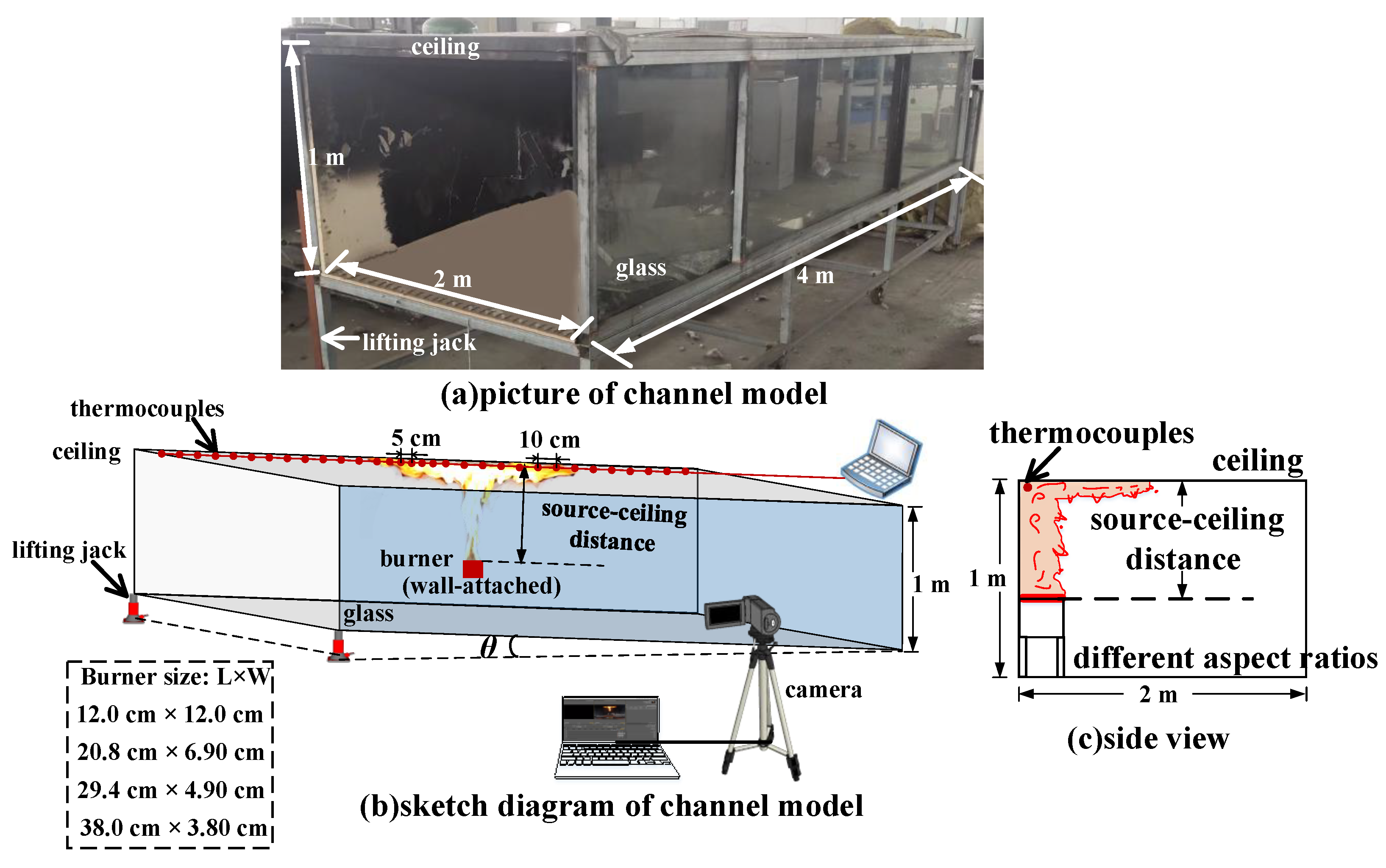
2.1. Experimental Rig and Measurements

A 1:8 reduced-scale experimental rig was constructed under the Froude scaling law [39], as shown in Figure 1. It was constructed with 2 cm-thick fireproof plates with dimensions of 2 m (width) × 1 m (height) × 8 m (length). And its slope can be adjusted to be 0%, 5%, 8%, and 10%, as shown in Figure 2a. Rectangular propane burners with various aspect ratios were used as a fire source, which were installed at the center of the channel and against the side wall to make a wall-attached fire. The dimensions of the cross-section of burners are 12 cm × 12 cm, 29.4 cm × 4.9 cm, and 38 cm × 3.8 cm, corresponding to aspect ratios of 1, 6, and 10, as illustrated in Figure 2c.
Heat release rates were controlled by adjusting the mass flow meter and estimated by assuming that the combustion efficiency is 1.0. This takes into account the fact that since the dimensions of the combustion chamber are much larger than the cross-sectional area of the burner and there is natural ventilation at both ends of the chamber. The height between the upper surface of the burner and the channel ceiling was defined as the source-ceiling height, which can be changed by adjusting the height of the burner surface. Three different source-ceiling distances were considered: 0.3 m, 0.4 m, and 0.5 m. A CCD camera facing the longitudinal direction of the channel model was employed to record the flame’s morphology.
Thirty-two K-type thermocouples, produced by Shanghai Automation Instrumentation Co, with a diameter of 1 mm and an uncertainty of less than 1 °C, were fixed 2 cm beneath the channel ceiling to measure the longitudinal temperature profile. Near the fire source (0.15 m), the thermocouples were dense to capture the sharp temperature gradient. Their spacing was 5 cm. Outside this region, the distance between two adjacent thermocouples was 10 cm.
With reference to the research experience of previous experiments related to fire research, the oil pool fire repeatability is good; hence, the experiments in this paper were conducted in triplicate, and the average value was used for analyses.

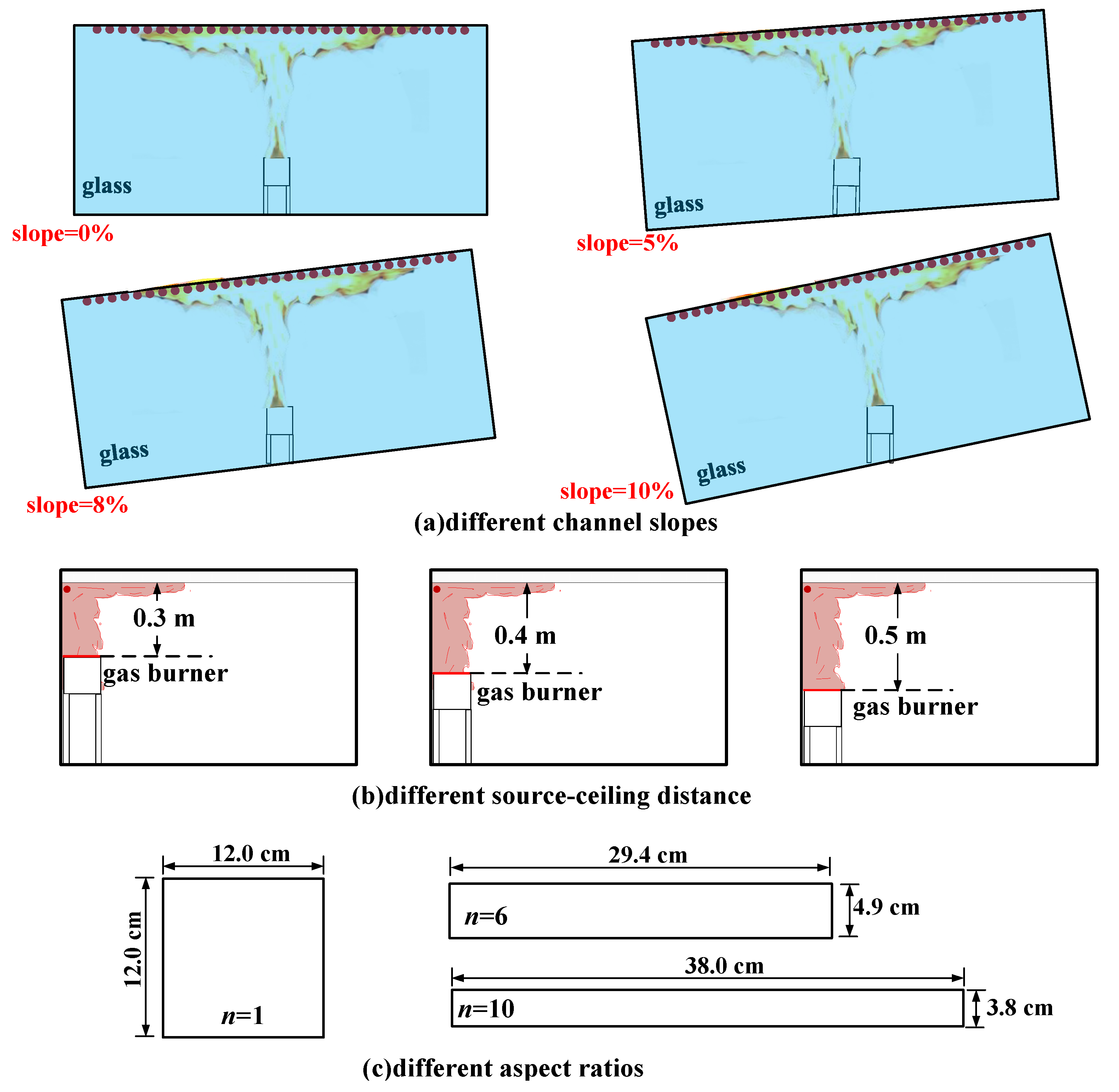
2.2. Experimental Condition Seetings

To investigate the influence of the burner aspect ratio, source-ceiling height, and channel slope on the longitudinal temperature profile, thirty-six tests were designed, as listed in Table 1. Three rectangular burners with the same cross-section area but different aspect ratios including 12 cm (length) × 12 cm (width), 29.4 cm (length) × 4.9 cm (width), and 38 cm (length) × 3.8 cm (width), which corresponds to the aspect ratio of n = 1, 6, and 10, respectively, were adopted [40,41]. Heat release rates were adjusted to vary between 20.16 kW to 67.2 kW. Four slopes (0%, 5%, 8%, and 10%) were considered to analyze the temperature profile. The Rayleigh number (Ra) and the Reynolds number (Re) of the fuel gas at the burner exit ranged from 5.82 × 10¹³ to 1.46 × 10¹⁴ and 1.55 × 10⁴ to 2.1 × 10⁴, respectively, indicating that the fuel flow is turbulent in this work.
The long side of the rectangular burner is close to the side wall, and the aspect ratio (n) of the rectangular burner is taken as 1, 6 and 10 [42], respectively, to simulate the real tunnel fire scene of vehicles of different sizes; The HRR is 20.16, 26.88, 33.60 and 40.32 kW, respectively, and the corresponding full-size fire power is 3.65, 4.87, 6.08 and 7.30 MW [43]; The source-ceiling height is taken as 0.3, 0.4 and 0.5 m, respectively, to simulate different distances between vehicles and the tunnel ceiling.
It should be noted that when the burner is consistent with the tunnel slope, the flame generated from the burner has a certain angle with the vertical direction. This deflection angle can be gradually corrected by increasing the source-ceiling distance. While the flame’s characteristics under the inclined tunnel ceiling were the research focus, the horizontal burner was therefore adopted to eliminate the effects of the fire source itself. Therefore, the burner keeps a horizontal orientation during the test.

3. Results and Discussion

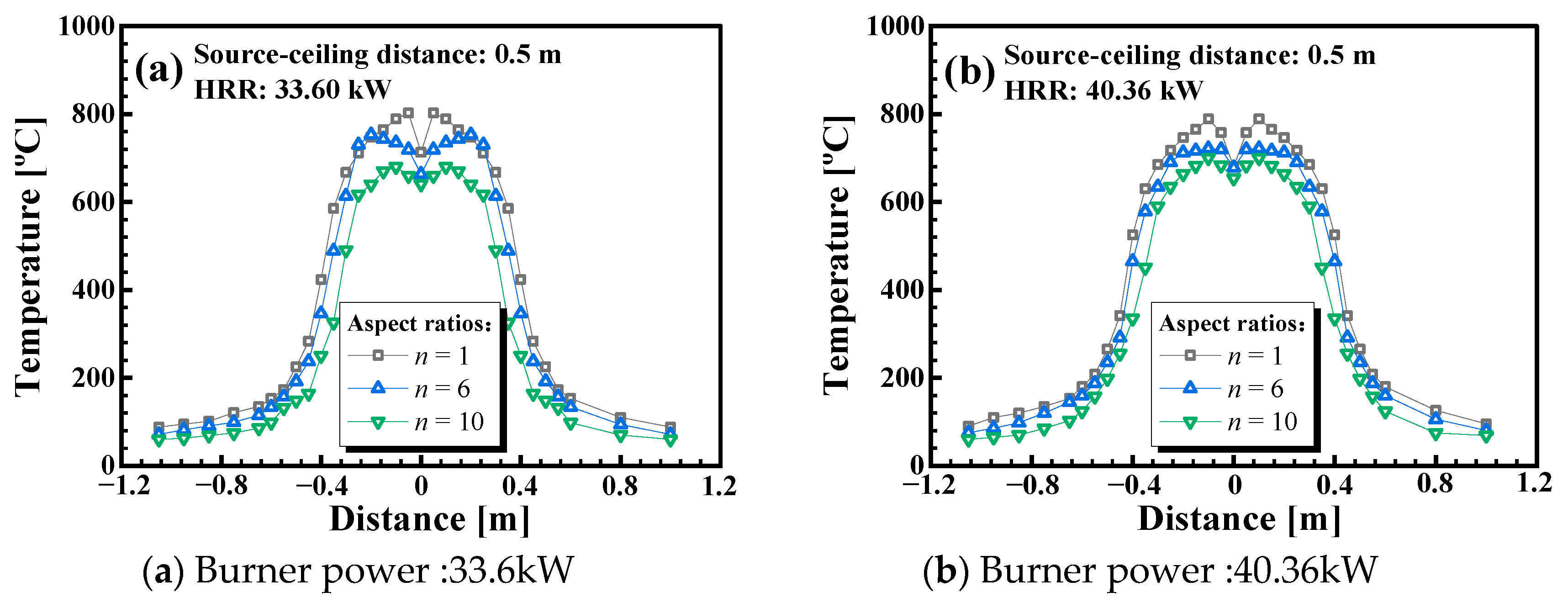
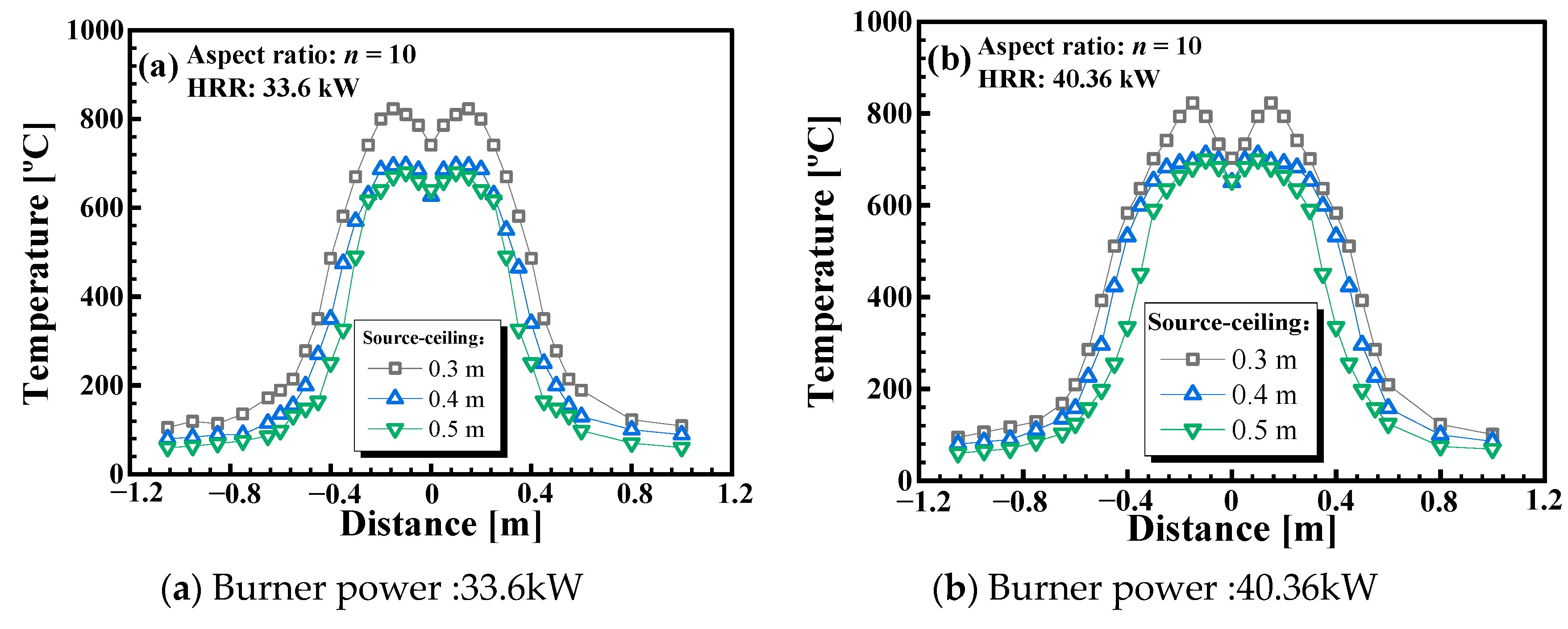
3.1. Influence of the Burner Aspect Ratios and Source-Ceiling Distance on the Longitudinal Temperature Profile Beneath a Horizontal Channel Ceiling

Figure 3 compares the longitudinal temperature profile beneath the horizontal ceiling of different burner aspect ratios. The source-ceiling height was kept at 0.5 m. An increase in the burner aspect ratio reduced the longitudinal temperature. This phenomenon is consistent with previous studies [43,44,45] and can be explained by air entrainment. When the cross-section of the burner remains unchanged, a larger burner aspect ratio means longer contact perimeter with the surrounding ambient air. If more ambient air could be entrained, the temperature would be relatively lower. When the source-ceiling height = 0.5 m, and HRR = 33.6 kW, the temperature difference between the stagnation points and the maximum temperature is about 90 °C with n = 6 and 10, while the temperature difference is about 40 °C with n = 1.
Figure 4 compares the longitudinal temperature profile beneath the horizontal ceiling with different source-ceiling distances. For simplicity, the burner aspect ratios were kept as 10. By increasing source-ceiling distance, the longitudinal temperature decreases. This phenomenon is obvious. A larger source-ceiling distance implies that it needs a longer distance for the fire plume to rise to the channel ceiling. During the longer distance, more ambient air could be entrained, so the longitudinal temperature is lower. In addition, when n = 10 and HRR = 33.6 kW, the temperature difference between the stagnation points and the maximum temperature is about 75 °C with the source-ceiling height = 0.3 and 0.4, while the temperature difference is about 40 °C with source-ceiling height = 0.5.

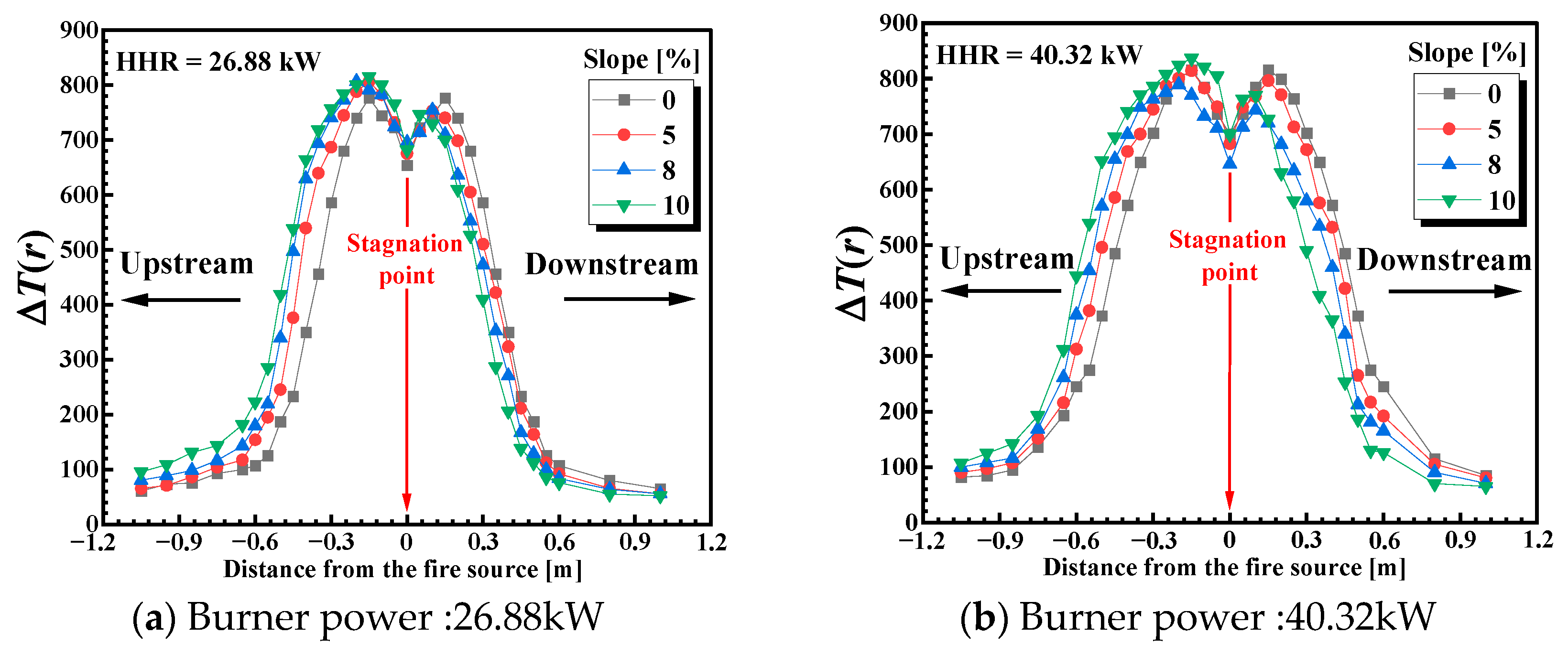
3.2. Influence of the Channel Slopes on the Longitudinal Temperature Profile Under the Ceiling

The channel slope causes asymmetric entrainment, thus affecting the longitudinal temperature distribution. As illustrated in Figure 5 obviously, when the slope is 0%, the longitudinal temperature profile is asymmetric. As the channel slope increases, the upstream temperature increases and the downstream temperature decreases. As the slope increases, the upward flow of flue gases along the inclined channel is more likely to be driven by buoyancy. An increase in slope equates to providing a more pronounced inclined channel where the flue gases are more easily entrained into the upstream. Thus, more hot smoke could be transported upstream, so the upstream temperature is higher.
In addition, right above the fire source, the temperature is lower, which is labeled as “stagnation point” in Figure 4. This is because at the stagnation point, the oxygen is relatively less, insufficient to consume all the available fuel gas. In contrast, in its adjacent region, the fuel gas is relatively less, and the combustion is more intense; hence, there is a “stagnation point” right above the fire source.
Figure 6 presents the flame morphology under different channel slopes, the burner aspect ratio and heat release rate are 3 and 33.6 kW, respectively. When the channel is horizontal, the flame is symmetric. The flame extension lengths on both sides are equal. With the increase in channel slope, the upstream flame extension length is longer than the downstream flame extension length. This phenomenon is due to the stack effect. With increasing channel slope, more unburnt gas could be transported upstream, resulting in a longer flame extension length.

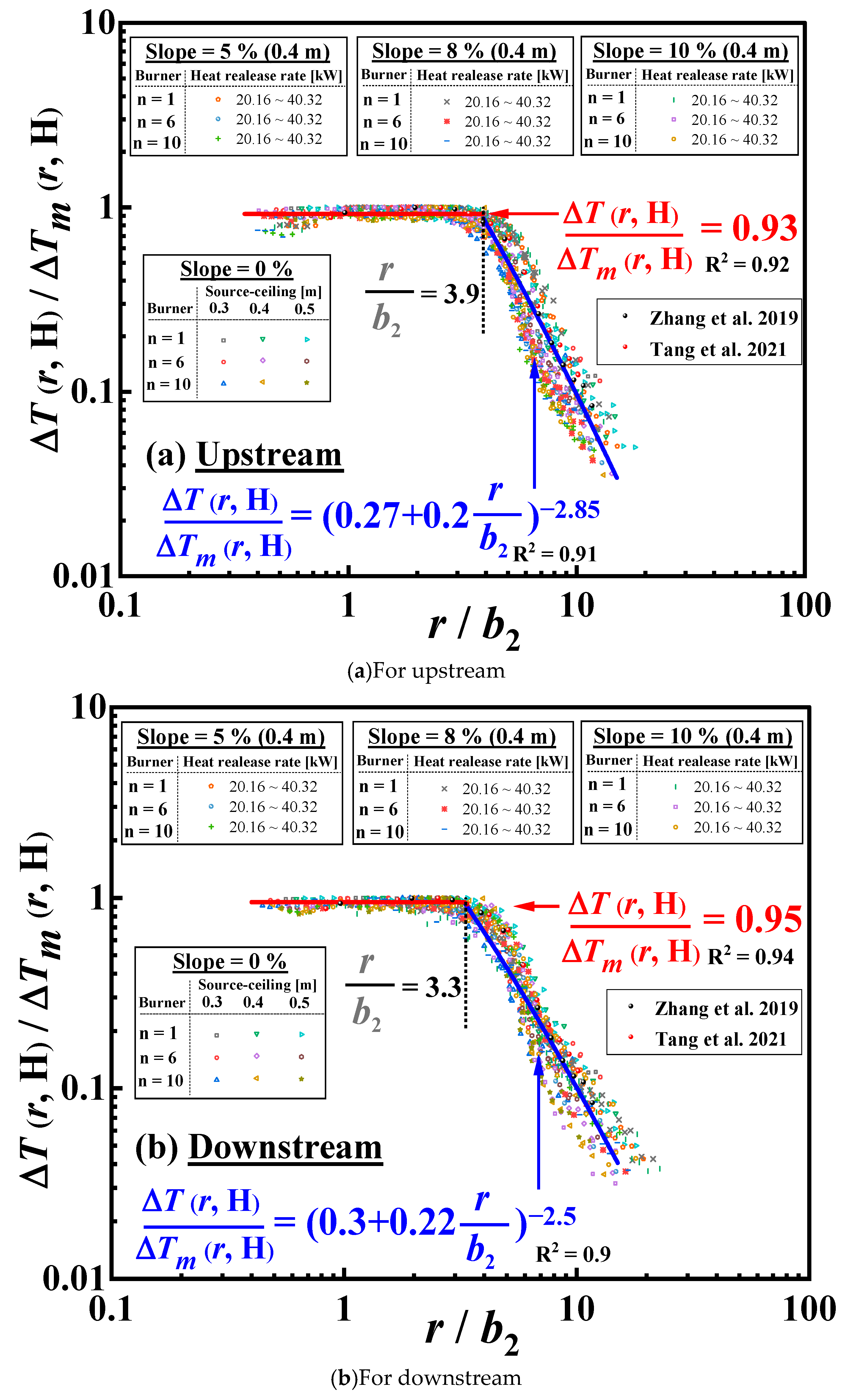
3.3. A Global Correlation of the Longitudinal Ceiling Temperature Profile in an Inclined Channel Ceiling Induced by a Wall-Attached Fire

The air entrainment of the wall-attached fire is restricted compared to axisymmetric fire sources; hence, the characteristic length scale b in Equation (1) should be modified. According to the “mirror image” principle [41,46,47,48], previous studies have explored the changing patterns of free flame perimeter under wall-blocking conditions. Base on it [49], the fire plume characteristics induced by wall-attached fire are approximately twice the HRR of axisymmetric fire sources, as illustrated in Figure 7.
Taking the relationship of various rectangle burner sizes into consideration, the burner aspect ratio will affect the temperature decay under the channel ceiling. A new characteristic diameter D* was introduced to weaken the influence of burner size [40], which can be expressed as follows:
D * = 2 S 1 / 2 n 1 / 2 + n 1 / 2 π
where S represents the equivalent area of the fire source. n represents the burner aspect ratios.
The side entrainment of the rectangular burner physically dominates the extension length of the ceiling flame, where the burner circumference should be the length scale. The source-ceiling heights will also affect the flame extension length under the channel ceiling. Taking the influence of n and d on the longitudinal temperature profile into account, a new characteristic length scale of a wall-attached fire, denoted by b1, could be expressed as follows:
b 1 = 0 . 42 ρ c P 4 / 5 T 3 / 5 g 2 / 5 1 / 2 T m ( H ) 1 / 2 2 D * / H Q ˙ c 2 / 5 Δ T m ( H ) 3 / 5
Figure 8 depicts the variation in non-dimensional temperature rise under the inclined channel ceiling with the characteristic length r/b1 from 5% to 10% at a given aspect ratio (n = 6). It is found that the non-dimensional temperature rise decreases with further distance from the ceiling center above the fire source. However, the dimensionless temperature decay under the ceiling between the upstream and downstream is a little scattered under different channel slopes. Therefore, it is necessary to further modify the characteristic length to weaken the influence of the channel slope, which is discussed below.
For the fire impingement on the inclined channel ceiling, there is an upward component force of the impingement flow in the upstream, which has the same direction as the buoyancy driving force, so the more unburned fuel exists at the upstream ceiling, leading to an increase in the flame extension length. The diagram of the inclined ceiling of physical analysis on the impingement region is depicted in Figure 9.
According to the continuity and the conservation of momentum under the ceiling, the unburned fuel ratio in the upward and downward directions to the total unburned fuel can be calculated [50]. Firstly, the mass flow rate of the unburned fuel after impinging is composed of the upward direction m ˙ U p and downstream directions m ˙ D o w n , and they added up to the total mass flow rate m ˙ of the unburned fuel before impinging. According to the Bernoulli relation [51], the momentum along the inclined channel ceiling in the flame impingement area in the longitudinal direction is conserved, while the mass flow rate ( m ˙ U p and m ˙ D o w n ) and velocities ( v U p and v D o w n ) of the upstream and downstream flows after impinging are different, providing the following:
m ˙ I n v I n sin θ = m ˙ U p v U p m ˙ D o w n v D o w n
where m ˙ I n and v I n are the mass flow rate and velocity of unburned fuel before impingement, respectively, and θ is the angle corresponding to the channel slope. According to the mass conservation, it further obtains the following:
m ˙ I n = m ˙ U p + m ˙ D o w n
Combining Equations (5) and (6) provides the following:
m ˙ U p ( 1 + sin θ ) m ˙ I n m ˙ D o w n ( 1 - sin θ ) m ˙ I n
By modifying Equation (3), a new characteristic length scale b 2 elaborating, the upward and downward component forces can be obtained as follows:
b 2 = 0 . 42 ρ c P 4 / 5 T 3 / 5 g 2 / 5 1 / 2 T m ( H ) 1 / 2 2 k θ 15 / 2 D * / H Q ˙ c 2 / 5 Δ T m ( H ) 3 / 5
where k θ is the slope correction factor. There are different forms in two directions, providing the following:
k θ = 1 + sin θ ,   for   the   upstream 1 sin θ ,   for   the   downstream
Figure 10 plots all the experimental data of a non-dimensional temperature rise measured with different slopes based on Equations (2)–(9) in the upstream and downstream. The dimensionless analytical approach [33,35] with reference to previous similar studies found that the non-dimensional temperature rise correlates well, and the established correlation is shown in Equation (10).
For upstream:
Δ T ( r , H ) Δ T m ( H ) = 0 . 93 r / b 2 < 3.9 0 . 27 + 0 . 2 r b 2 2 . 85 r / b 2 3.9
For downstream:
Δ T ( r , H ) Δ T m ( H ) = 0 . 95 r / b 2 < 3 . 3 0 . 3 + 0 . 22 r b 2 2 . 5 r / b 2 3 . 3
To verify Equation (10), data from previous works [21,42] studying non-dimensional temperature rise under a horizontal channel ceiling caused by a strong fire plume with different HRRs and burner aspect ratios are introduced in Figure 10. And the results confirm that the model proposed is valid. The proposed correlation also agrees with the temperature profile in others’ work reasonably.

4. Conclusions

In this work, the longitudinal temperature profile induced by a wall-attached fire in an inclined channel was experimentally investigated. The HRRs (20.16–40.32 kW), the burner aspect ratios (1, 6, and 10), and channel slopes (0–10%) were taken into consideration to analyze the influence of the above factors on the longitudinal temperature profile. The major findings are as follows:
(1)
For the channel fire with a horizontal ceiling, the influence of burner aspect ratio and source-ceiling height on the temperature profile is monotonous in the cases considered in this work. With a larger burner aspect ratio and larger source-ceiling distance, more ambient air can be entrained; hence, the longitudinal temperature under the ceiling decays faster.
(2)
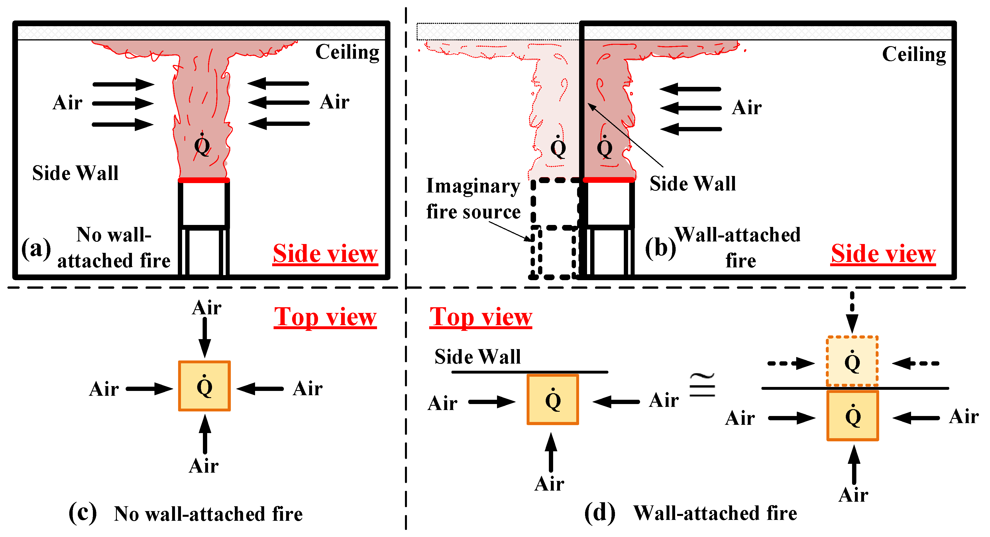
For the channel fire with an inclined ceiling, when the burner aspect ratio and source-ceiling distance are constant, under a larger channel slope, more hot smoke could be transported upstream due to the asymmetric entrainment effect. Hence, the temperature profile is not symmetric, with higher temperatures upstream and lower temperatures downstream.
(3)
Combining the influence of burner aspect ratios, source-ceiling distance, and burner aspect ratio, the characteristic length scale was modified. Based on this, a model describing the ceiling temperature profile was proposed and then verified with previous data.
This paper experimentally studied the longitudinal temperature profile induced by a wall-attached fire in an inclined channel, considering burner aspect ratios, source-ceiling distance, and channel slopes. A global correlation of the longitudinal temperature profile was proposed. However, this work only considered the longitudinal temperature profile under natural ventilation, it is acknowledged that this approach has its limitations. In practical scenarios, mechanical ventilation is typically employed during channel fires to exhaust hot smoke. Thus, future work will prioritize exploring the temperature profile under mechanical ventilation, with particular emphasis on varying burner aspect ratios, source-ceiling distances, and channel slopes.

Author Contributions

Conceptualization, X.H. and Z.T.; methodology, Y.Z.; software, Z.T. and W.W.; validation, Y.Z. and W.W.; formal analysis, X.H.; investigation, X.H.; resources, Z.T.; data curation, X.H.; writing—original draft preparation, X.H. and W.W.; writing—review and editing, Z.T.; visualization, Y.Z.; supervision, Z.T.; project administration, Z.T.; funding acquisition, Z.T and W.W. All authors have read and agreed to the published version of the manuscript.

Funding

This research was Supported by the Opening Funds of State Key Laboratory of Building Safety and Built Environment and National Engineering Research Center of Building Technology (Grant No. BSBE2022-10), Technology Development Program of SINOPEC (Grant No. 323139), and the Science and Technology Research Project of Shanghai Science and Technology Commission (22DZ1201000).

Data Availability Statement

The original contributions presented in this study are included in the article. Further inquiries can be directed to the corresponding author.

Conflicts of Interest

The authors declare no conflicts of interest.

References

  1. Ren, R.; Zhou, H.; Hu, Z.; He, S.; Wang, X. Statistical analysis of fire accidents in Chinese highway tunnels 2000–2016. Tunn. Undergr. Space Technol. 2019, 83, 452–460. [Google Scholar] [CrossRef]
  2. Liu, J.; Chen, M.; Lin, X.; Yuen, R.; Wang, J. Impacts of ceiling height on the combustion behaviors of pool fires beneath a ceiling. J. Therm. Anal. Calorim. 2016, 126, 881–889. [Google Scholar] [CrossRef]
  3. Zhang, S.; Ni, X.; Zhao, M.; Zhang, R.; Zhang, H. Experimental study on the characteristics of wood crib fire in a confined space with different ventilation conditions. J. Therm. Anal. Calorim. 2015, 120, 1383–1391. [Google Scholar] [CrossRef]
  4. Tang, F.; He, Q.; Chen, L.; Li, P. Experimental study on maximum smoke temperature beneath the ceiling induced by carriage fire in a tunnel with ceiling smoke extraction. Sustain. Cities Soc. 2018, 44, 40–45. [Google Scholar] [CrossRef]
  5. Casey, N. Fire incident data for Australian road tunnels. Fire Saf. J. 2020, 111, 102909. [Google Scholar] [CrossRef]
  6. Zhang, S.; Ni, X.; Zhao, M.; Feng, J.; Zhang, R. Numerical simulation of wood crib fire behavior in a confined space using cone calorimeter data. J. Therm. Anal. Calorim. 2015, 119, 2291–2303. [Google Scholar] [CrossRef]
  7. Fan, C.G.; Yang, J.; Li, M.H. A theoretical and experimental study of flame length under a tunnel ceiling. J. Therm. Anal. Calorim. 2016, 128, 1143–1149. [Google Scholar] [CrossRef]
  8. Chen, X.; Lu, S.; Ding, Z. Initial fuel depth effect on the burning characteristics of thin-layer pool fire in a confined enclosure. J. Therm. Anal. Calorim. 2019, 139, 1409–1418. [Google Scholar] [CrossRef]
  9. Tang, F.; Zhao, Z.; Zhao, K. Experimental investigation on carriage fires hazards in the longitudinal ventilated tunnels: Assessment of the smoke stratification features. Saf. Sci. 2020, 130, 104901. [Google Scholar] [CrossRef]
  10. Tang, F.; Chen, L.; Chen, Y.; Pang, H. Experimental study on the effect of ceiling mechanical smoke extraction system on transverse temperature decay induced by ceiling jet in the tunnel. Int. J. Therm. Sci. 2020, 152, 106294. [Google Scholar] [CrossRef]
  11. Zhu, Y.; Tang, F.; Zhao, Z.; Wang, Q. Effect of lateral smoke extraction on transverse temperature distribution and smoke maximum temperature under ceiling in tunnel fires. J. Therm. Anal. Calorim. 2022, 147, 4275–4284. [Google Scholar] [CrossRef]
  12. Tang, F.; Cao, Z.; Palacios, A.; Wang, Q. A study on the maximum temperature of ceiling jet induced by rectangular-source fires in a tunnel using ceiling smoke extraction. Int. J. Therm. Sci. 2018, 127, 329–334. [Google Scholar] [CrossRef]
  13. Wang, Z.; Wang, X.; Huang, Y.; Tao, C.; Zhang, H. Experimental study on fire smoke control using water mist curtain in channel. J. Hazard. Mater. 2018, 342, 231–241. [Google Scholar] [CrossRef]
  14. Alpert, R.L. Turbulent ceiling-jet induced by large-scale fires. Combust. Sci. Technol. 1975, 11, 197–213. [Google Scholar] [CrossRef]
  15. Heskestad, G.; Hamada, T. Ceiling jets of strong fire plumes. Fire Saf. J. 1993, 21, 69–82. [Google Scholar] [CrossRef]
  16. Chen, L.; Tang, F.; Wang, Q.; Li, L.-J. Experimental study on temperature distribution of ceiling jet in tunnel fires under natural ventilation. Procedia Eng. 2018, 211, 674–680. [Google Scholar] [CrossRef]
  17. Hasemi, Y.; Tokunaga, T. Flame geometry effects on the buoyant plumes from turbulent diffusion flames. Fire Sci. Technol. 1984, 4, 15–26. [Google Scholar] [CrossRef]
  18. Hasemi, Y.; Nishihata, M. Fuel shape effect on the deterministic properties of turbulent diffusion flames. Fire Saf. Sci. 1989, 2, 275–284. [Google Scholar] [CrossRef]
  19. Hu, L.; Liu, S.; Zhang, X. Flame heights of line-source buoyant turbulent non-premixed jets with air entrainment constraint by two parallel side walls. Fuel 2017, 200, 583–589. [Google Scholar] [CrossRef]
  20. Hu, L.H.; Huo, R.; Wang, H.B.; Li, Y.Z.; Yang, R.X. Experimental studies on fire-induced buoyant smoke temperature distribution along tunnel ceiling. Build. Environ. 2007, 42, 3905–3915. [Google Scholar] [CrossRef]
  21. Zhang, X.; Hu, L.; Delichatsios, M.A.; Zhang, J. Experimental study and analysis on flame lengths induced by wall-attached fire impinging upon an inclined ceiling. Proc. Combust. Inst. 2019, 37, 3879–3887. [Google Scholar] [CrossRef]
  22. Zhang, X.; Hu, L.; Zhu, W.; Zhang, X.; Yang, L. Flame extension length and temperature profile in thermal impinging flow of buoyant round jet upon a horizontal plate. Appl. Therm. Eng. 2014, 73, 15–22. [Google Scholar] [CrossRef]
  23. Shi, C.; Liu, W.; Hong, W.; Zhong, M.; Zhang, X. A modified thermal radiation model with multiple factors for investigating temperature rise around pool fire. J. Hazard. Mater. 2019, 379, 120801. [Google Scholar] [CrossRef]
  24. Delichatsios, M.A. Air entrainment into buoyant jet flames and pool fires. Combust. Flame 1987, 70, 33–46. [Google Scholar] [CrossRef]
  25. Zukoski, E.E. Mass flux in fire plumes. Fire Saf. Sci. 1994, 4, 137–147. [Google Scholar] [CrossRef]
  26. Kong, X.X.; Wang, X.S.; Cong, H.Y.; Liu, Y.P.; Zhu, J.P. Temperature profile and flame extension length of a ceiling impinging round jet fire in an inclined tunnel. Int. J. Therm. Sci. 2019, 137, 526–533. [Google Scholar] [CrossRef]
  27. Hu, L.; Zhang, X.; Zhang, X.; Yang, L. A re-examination of entrainment constant and an explicit model for flame heights of rectangular jet fires. Combust. Flame 2014, 161, 3000–3002. [Google Scholar] [CrossRef]
  28. Lei, P.; Chen, C.; Zhang, Y.; Xu, T.; Sun, H. Experimental study on temperature profile in a branched tunnel fire under natural ventilation considering different fire locations. Int. J. Therm. Sci. 2021, 159, 106631. [Google Scholar] [CrossRef]
  29. Lei, P.; Chen, C.; Zhao, D.; Zhang, Y.; Xu, T.; Jiao, W. Study on heat allocation and temperature profile in a T-shaped branched tunnel fire with different branch slopes under natural ventilation. Tunn. Undergr. Space Technol. 2022, 126, 104508. [Google Scholar] [CrossRef]
  30. Zhao, D.; Chen, C.; Lei, P.; Xu, T.; Jiao, W.; Zhang, Y. Experimental study on temperature profile and smoke movement in a model-branched tunnel fire under longitudinal ventilation. Tunn. Undergr. Space Technol. 2022, 121, 104324. [Google Scholar] [CrossRef]
  31. Zhang, X.; Guo, Z.; Tao, H.; Liu, J.; Chen, Y.; Liu, A.; Xu, W.; Liu, X. Maximum temperature of thermal plume beneath an unconfined ceiling with different inclination angles induced by rectangular fire sources. Appl. Therm. Eng. 2017, 120, 239–246. [Google Scholar] [CrossRef]
  32. Wang, J.; Lu, S.; Guan, Y.; Lo, S.; Zhang, H. Experiment Investigation on the Influence of Low Pressure on Ceiling Temperature Profile in Aircraft Cargo Compartment Fires. Appl. Therm. Eng. 2015, 89, 526–533. [Google Scholar] [CrossRef]
  33. Tao, Z.; Yang, R.; Li, C.; Yao, Y.; Zhang, P.; Zhang, H. An Experimental Study on Fire Behavior of an Inclined Ceiling Jet in a Low-Pressure Environment. Int. J. Therm. Sci. 2019, 138, 487–495. [Google Scholar] [CrossRef]
  34. Kan, K.; Yang, Z.; Lyu, P.; Zheng, Y.; Shen, L. Numerical study of turbulent flow past a rotating axial-flow pump based on a level-set immersed boundary method. Renew. Energy 2021, 168, 960–971. [Google Scholar] [CrossRef]
  35. Zhang, X.; Hu, L.; Sun, X. Temperature Profile of Thermal Flow Underneath an Inclined Ceiling Induced by a Wall-Attached Fire. Int. J. Therm. Sci. 2019, 141, 133–140. [Google Scholar] [CrossRef]
  36. Ren, N.; Wang, Y.; Vilfayeau, S.; Trouvé, A. Large eddy simulation of turbulent vertical wall fires supplied with gaseous fuel through porous burners. Combust. Flame 2016, 169, 194–208. [Google Scholar] [CrossRef]
  37. Zhang, X.; Shi, C.; Hu, L. Temperature profile of impingement flow in the corner between wall and inclined ceiling induced by gaseous fuel jet flame. Fuel 2020, 259, 116232. [Google Scholar] [CrossRef]
  38. Kan, K.; Chen, H.; Zheng, Y.; Zhou, D.; Binama, M.; Dai, J. Transient characteristics during power-off process in a shaft extension tubular pump by using a suitable numerical model. Renew. Energy 2021, 164, 109–121. [Google Scholar] [CrossRef]
  39. Quintiere, J.G. Scaling applications in fire research. Fire Saf. J. 1989, 15, 3–29. [Google Scholar] [CrossRef]
  40. Tang, F.; Hu, L.; Zhang, X.; Zhang, X.; Dong, M. Burning rate and flame tilt characteristics of radiation-controlled rectangular hydrocarbon pool fires with cross air flows in a reduced pressure. Fuel 2015, 139, 18–25. [Google Scholar] [CrossRef]
  41. Tang, F.; Hu, P.; Wen, J. Experimental investigation on lateral ceiling temperature distribution induced by wall-attached fire with various burner aspect ratios in underground space. Fire Saf. J. 2020, 120, 103055. [Google Scholar] [CrossRef]
  42. Tang, F.; Deng, L.; Chen, L.; Wang, Q. Effects of burner aspect ratio on heat flux distributions beneath unconfined ceilings with different inclination angles. Combust. Flame 2021, 228, 99–106. [Google Scholar] [CrossRef]
  43. Tao, C.; Qian, Y.; Tang, F.; Wang, Q. Experimental investigations on temperature profile and air entrainment of buoyancy-controlled jet flame from inclined nozzle bounded the wall. Appl. Therm. Eng. 2017, 111, 510–515. [Google Scholar] [CrossRef]
  44. Tao, C.F.; Shen, Y.; Zong, R.W.; Tang, F. An experimental study of flame height and air entrainment of buoyancy-controlled jet flames with sidewalls. Fuel 2016, 183, 164–169. [Google Scholar] [CrossRef]
  45. Tao, C.F.; Shen, Y.; Zong, R.W. Experimental study on virtual origins of buoyancy-controlled jet flames with sidewalls. Appl. Therm. Eng. 2016, 106, 1088–1093. [Google Scholar] [CrossRef]
  46. Hasemi, Y.; Tokunaga, T. Some experimental aspects of turbulent diffusion flames and buoyant plumes from fire sources against a wall and in a corner of walls. Combust. Sci. Technol. 1984, 40, 1–18. [Google Scholar] [CrossRef]
  47. Hu, L.; Li, Y.; Huo, R.; Yi, L.; Shi, C.; Chow, W.K. Experimental studies on the rise-time of buoyant fire plume fronts induced by pool fires. J. Fire Sci. 2004, 22, 69–86. [Google Scholar] [CrossRef]
  48. Zhang, X.; Tao, H.; Zhang, Z.; Tang, F.; Su, G.; Chen, S.; Liu, J. Temperature profile beneath an inclined ceiling induced by plume impingement of gas fuel jet flame. Fuel 2018, 223, 408–413. [Google Scholar] [CrossRef]
  49. Huang, X.; Wang, Y.; Zhu, H.; He, L.; Tang, F.; Wen, J. Experimental Study on the Radiant Heat Flux of Wall-Attached Fire Plume Generated by Rectangular Sources. Int. J. Therm. Sci. 2021, 159, 106605. [Google Scholar] [CrossRef]
  50. Zhang, X.; Tao, H.; Xu, W.; Liu, X.; Li, X.; Zhang, X.; Hu, L. Flame Extension Lengths beneath an Inclined Ceiling Induced by Rectangular-Source Fires. Combust. Flame 2017, 176, 349–357. [Google Scholar] [CrossRef]
  51. Malalasekera, W.; Versteeg, H. An Introduction to Computational Fluid Dynamics; World Book Publishing Corp: Chicago, IL, USA, 2000. [Google Scholar]
Figure 1. Illustration of experimental rig.
Fire 08 00222 g001
Figure 2. Schematic diagram of different slopes, aspect ratios, and source-ceiling distance.
Fire 08 00222 g002
Figure 3. Influence of the burner aspect ratio on the longitudinal temperature profile of the wall-attached fire.
Fire 08 00222 g003
Figure 4. Influence of the source-ceiling height on the longitudinal temperature profile of the wall-attached fire.
Fire 08 00222 g004
Figure 5. Longitudinal temperature profile of wall-attached fire with varying channel slopes.
Fire 08 00222 g005
Figure 6. Flame morphology under different channel slopes (n = 3, HRR = 33.6 kW).
Fire 08 00222 g006
Figure 7. Illustration of the mirror principle of the ceiling jet in the channel.
Fire 08 00222 g007
Figure 8. Non-dimensional temperature rise against the new characteristic length r/b1 beneath the ceiling.
Fire 08 00222 g008
Figure 9. Diagram of inclined ceiling analysis.
Fire 08 00222 g009
Figure 10. The global correlation of the non-dimensional temperature rises with r/b2 under the ceiling of both (a) the upstream and (b) the downstream [21,38].
Fire 08 00222 g010
Table 1. Experimental conditions.
Test No.Burner Size [cm × cm]Aspect RatioSlope [%]Source-Ceiling Distance [m]
T1–T1212.0 × 12.0100.3, 0.4, 0.5
T13–T2429.4 × 4.90600.3, 0.4, 0.5
T25–T3638.0 × 3.801000.3, 0.4, 0.5
T37–T4812.0 × 12.015, 8, 100.4
T49–T6029.4 × 4.9065, 8, 100.4
T61–T7238.0 × 3.80105, 8, 100.4
Note: four different heat release rates, including 20.16 kW, 26.88 kW, 33.60 kW, and 40.36 kW, were considered.
Disclaimer/Publisher’s Note: The statements, opinions and data contained in all publications are solely those of the individual author(s) and contributor(s) and not of MDPI and/or the editor(s). MDPI and/or the editor(s) disclaim responsibility for any injury to people or property resulting from any ideas, methods, instructions or products referred to in the content.

