Article

Research on Vaporization and Sudden Cooling Performance of Heptafluoropropane in Prefabricated Fire-Extinguishing Devices Based on Numerical Method

1
Key Laboratory of Fire Protection Technology for Industry and Public Building, Ministry of Emergency Management, Tianjin 300381, China
2
Tianjin Fire Science and Technology Research Institute of MEM, Tianjin 300381, China
3
College of Energy and Power Engineering, Changsha University of Science & Technology, Changsha 410076, China
*
Author to whom correspondence should be addressed.
Fire 2025, 8(4), 124; https://doi.org/10.3390/fire8040124
Submission received: 25 January 2025 / Revised: 13 March 2025 / Accepted: 18 March 2025 / Published: 23 March 2025

Abstract

With the safety and reliability of the electrical equipment used in information systems becoming more important, prefabricated fire-extinguishing devices using heptafluoropropane as the extinguishing agent have broad application prospects. However, few studies have focused on the vaporization performance of heptafluoropropane in the context of fire suppression and the safe distance for electrical equipment. This study proposes a numerical simulation model to analyze the vaporization and cooling performance of sprayed heptafluoropropane. First, experimental measurements with no fire source are performed to verify the numerical model. Through numerical and experimental methods, the temperature, concentration, and velocity distribution of the sprayed heptafluoropropane are analyzed to improve its vaporization performance and determine the safe distance. Finally, heptafluoropropane spraying with a fire source is simulated, allowing for the discussion of its cooling effect and fire-extinguishing performance. The results illustrate that the mass ratio of liquid and gas phases in the sprayed heptafluoropropane are 20.2% and 79.8%, respectively. Heptafluoropropane spraying reduced the average temperature in the protective room, with the final value reaching 270 K. The mass fraction of the heptafluoropropane maintained a value of 0.1 at a distance of 0.8 m in front of the nozzle axis. The main findings of this research indicate the temperature variation and fluid flow performance associated with heptafluoropropane spraying, as well as providing a reference value for a safe distance from the nozzle.

1. Introduction

With the continuous development of electrical equipment and information systems, their safety and reliability are becoming more and more important [1,2]. Gas fire-extinguishing systems are essential parts of data storage centers and electrical distribution rooms, which comprise pipe network and prefabricated types [1,3,4]. Among these two types, prefabricated gas fire-extinguishing devices are widely used, due to their low cost and convenience of installation [5,6].
The performance of a prefabricated gas fire-extinguishing system is important for maintaining the safety of electrical rooms and data centers. Commonly used fire-extinguishing agents in prefabricated systems include heptafluoropropane and carbon dioxide (CO2) [3]. Heptafluoropropane is an odorless fire-extinguishing agent with no electrical conductivity [7,8] which facilitates chemical and physical reactions to generate flame-retardant substances. Additionally, the cooling and asphyxiation processes also inhibit the spread of the fire. Meanwhile, CO2 is an agent for flammable liquid and solid material fires, which reduces the volume rate of the oxygen [9,10]. The average temperature of the fire-extinguishing region decreases through a heat absorption process. These two working fluids are both considered efficient for the prevention of fires in electrical rooms and data centers.
Many scientists have already investigated the performance of heptafluoropropane and CO2 through experimental measurements or numerical simulations. Regarding heptafluoropropane, García et al. [11,12] set up an experimental platform for fire-extinguishing or thermal runaway tests in lithium batteries. The flame temperature and the volume fraction of heptafluoropropane were obtained for the guidance of fire suppression. Cao et al. [13,14] investigated the inhabitation of heptafluoropropane on explosions in an enclosed room. The optimal methane equivalence ratio, the particle sizes, and the operating pressure were the main effects which led to better inhibition performance. Robin [15] studied the characteristics of heptafluoropropane on fire suppression. The results illustrated that heptafluoropropane was effective in suppressing the class a fire with certain value of concentration. The CO2 is another efficient gas fire-extinguishing agent, which is used in underground pipelines, cargo ships, and so on. Roy et al. [16] have tested the mole fraction of several species of the fire extinguishing agent to improve the efficiency. CO2 spraying reduced the required time for the temperature to drop and led to oxygen isolation effects. Wu et al. [17] carried out experimental measurements of CO2 agents to trace their mitigating effects on a hydrogen jet. Some parameters were selected and calculated, in order to determine the limits of the fire-extinguishing system for safe operations. Aydin [18] analyzed the human reliability of safety for the CO2 fire-extinguishing system in a marine ship. Some suggestions were provided for the prevention of errors, including training and monitoring.
In order to study the mechanisms of fire-extinguishing agents, researchers have performed numerical simulations to optimize the extinguishing time and field distribution visualization. Tanaka et al. [19] studied the fire-extinguishing performance of water mist under several conditions in a structure of 1.6 m wide, 1.6 m deep, and 3.15 m high. The required volumetric flow rates were predicted and compared through numerical method. The fine water mist was also applied for the suppression of a hydrogen jet fire on a fuel cell ship. The suitable choice of parameters for velocity and droplet size reduced the temperatures of the fire field effectively [20,21]. Ma et al. [22] assessed the extinguishing performance of varying ventilation approaches under various conditions in a 1:10 experiment. The results demonstrated that longitudinal ventilation could diminish the temperature and the backflow of the smoke. Nikam et al. [23] proposed a new composite extinguishing agent with polyurethane as a flame retardant. Its efficiency was improved at a mass fraction of 3%. Salehi et al. [24] optimized the structure layout of the smoke extraction system for the effective detection of fire risks. The visibility of the fire scenario was increased by 50%, which confirmed the efficacy of the proposed methodology. Bolshova et al. [25] investigated the synergy of two chemical inhibitors through numerical simulation, and found that increases in the initial temperature of the mixture components could improve their synergistic efficiency.
The cooling effect of heptafluoropropane and CO2 spraying from nozzles can lead to successful fire-extinguishing, which is due to suppression of the flame and isolation of the air [9,26]. The cooling effect is a result of the vaporization of the two working fluids, which requires large amount of heat. CO2 has a relatively higher saturated vapor pressure under the same temperature conditions and, thus, needs more heat to vaporize [27]. Simultaneously, the minimum average temperature of the spray region will drop sharply below 223.15 K [28]; this phenomenon is called local sudden cooling, and can cause failure in electrical devices [29]. Compared with CO2, heptafluoropropane has a relatively higher sudden cooling temperature and requires less heat [30,31], which means that the cooling effect is less significant. Considering the vaporization and the cooling effect, heptafluoropropane is suitable for fire suppression in electrical rooms and data centers. Some researchers have studied the vaporization processes of nozzles through many experimental measurements [32,33]. Temperatures, cooling rates, and spraying times are typically obtained to assess the cooling performance [34]. However, the mechanism driving the vaporization of heptafluoropropane in the context of fire suppression is still unclear. Some experimental studies on battery fire suppression have been conducted to assess the temperature variation of heptafluoropropane and associated thermal runaway characteristics [11,35]. Explosions have also been shown to be suppressed by heptafluoropropane, due to the cooling and inhibition effect [14,36]. These studies have focused on the results of effective fire suppression processes, while the fluid flow and phase change processes of heptafluoropropane were not quantitatively analyzed. Additionally, due to the cooling effect, the safe distance between the prefabricated fire-extinguishing device and protected equipment needs to be considered. Wang et al. [37] compared the fire-extinguishing performances of different agents, and found that heptafluoropropane suppressed a wood fire best within a 21 m3 test space. The results illustrated the efficiency of the extinguishing agent but lacked consideration of potential damage to the protected equipment. The cooling effect of heptafluoropropane has been studied in a test room at certain distances, in order to obtain the temperature drop, cooling rate, and cooling time [38]; however, the safe distances in an actual protective room require further study for improvement of its fire-extinguishing performance. Therefore, theoretical models are needed to investigate the vaporization of heptafluoropropane, leading to the cooling effect, in practical protective rooms. CFD simulations are applied to obtain the safe distance, thus guiding the installation of prefabricated gas fire-extinguishing devices.
The key contribution of this study is to fill the gap in theoretical analyses of the vaporization performance of heptafluoropropane in the context of fire-extinguishing systems through numerical simulation. In this work, a numerical simulation model of its vaporization is first established. Then, the prefabricated fire-extinguishing process is simulated to investigate the vaporization rate, concentration, temperature variations, and velocity distribution. In this way, the safe distance between the fire-extinguishing device and protected equipment is obtained. Additionally, experimental measurements using an actual model at a 1:1 scale are carried out, in order to verify the numerical method. Finally, heptafluoropropane spraying of a fire source is simulated to analyze its cooling effect and fire-extinguishing performance in a protective room.

2. Theoretical Analyses and Modeling of the Vaporization Processes of Heptafluoropropane

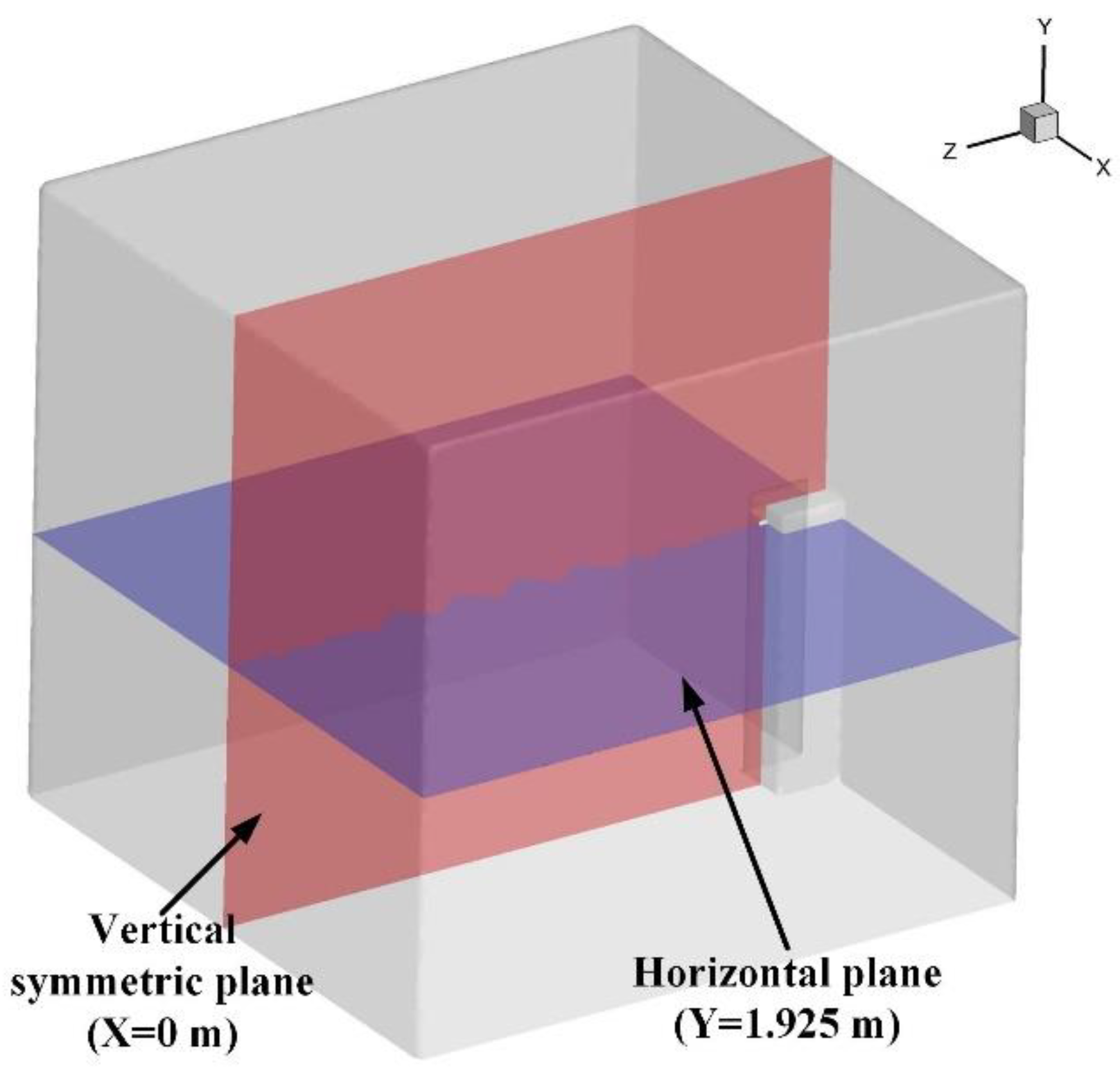
2.1. The Geometry of the Prefabricated Fire-Extinguishing Device and Protective Room

Figure 1a shows the geometry of the prefabricated fire-extinguishing device and protective room. The protective room space is constructed as a cuboid enclosed area with an operating door and a ventilation hole, thus modeling the circumstances of a data center. The ventilation hole is installed on the top area of the side wall. The prefabricated fire-extinguishing device is placed opposite the room’s door. The nozzle is installed on the device, which controls the atomization and vaporization processes of the heptafluoropropane. Figure 1b shows the detailed structure of the nozzle, with 12 holes. The interior zone of the nozzle forms a contraction channel, with eight small holes on the trapezoidal surface. In the front view, the angle between the centerline of two adjacent holes is 45°. Three holes are distributed on top of the nozzle, while there is one hole on the bottom. The geometric parameters of the detailed structure are listed in Table 1. The dimensions of the prefabricated fire-extinguishing device are 2.05 m × 0.47 m × 0.43 m.

2.2. The Numerical Model of the Vaporization Processes

In the vaporization process, heptafluoropropane is released from the high-pressure cabinet and sprayed from the nozzle, breaking it into small droplets. These small droplets absorb heat in the protective room, promoting the vaporization process which results in temperature reduction and oxygen isolation. As the heptafluoropropane continues to vaporize and diffuse, it forms a multi-component mixture with air in the protective room. Due to the effects of concentration and temperature gradients, the convection and diffusion of each component follows the species transport model. The release process leads to the multi-phase existence of heptafluoropropane, with strong interactions between the phases. The Euler model is suitable for solving liquid–gas multi-phase flow issues, allowing one to obtain accurate numerical results for the fluid flow field [39]. Additionally, as gas and liquid phases are present during heptafluoropropane spraying, the discrete phase model (DPM) can track the trajectories of droplets and visualize the vaporization process [40]. Therefore, the species transport equation, Eulerian model, and DPM are applied for modeling of the diffusion and vaporization processes in this study.
For the fluid flow of the heptafluoropropane in the whole process, the governing equations should satisfy the conservation laws of mass, energy, and momentum, which are expressed as follows [41].
Mass conservation:
ρ t + ( ρ u ) = 0
Momentum conservation:
ρ ( u t + ( u u ) ) = μ 2 u + ρ g p + S u
The conservation of energy:
( ρ T ) t + ( ρ u T ) = ( λ c p T ) + S T
where ρ, t, λ, and cp denote the density, flow time, thermal conductivity, and specific heat, respectively, while u, T, ρg, Su, and ST represent the velocity vector, temperature, gravitational force, source term caused by the fluid velocity field, and the heat source, respectively.
During the convection and diffusion processes of heptafluoropropane, the species transport model is used to calculate the concentration of each component in the mixture. The model reflects the transport and diffusion of heptafluoropropane caused by turbulence, temperature, and concentration gradients, which is expressed as [42]
( ρ Y i ) t + ( ρ Y i U ) = ( ( ρ D i . m + μ t S c t ) Y i ) + ( D T , i T T )
where Yi is the local mass fraction of species i in the convection and diffusion process; Di,m and DT,i are the mass diffusion and thermal diffusion coefficients of species i in the mixture, respectively; μt denotes the turbulent viscosity; and Sct is the turbulent Schmidt number.
In the release process of the high-pressure fire cabinet, the Eulerian model is used to capture the interfaces of gas and liquid phases for heptafluoropropane. The volume fraction, momentum, and energy conservation of the fluid are considered, with the velocity, pressure, and temperature distribution considered to be uniform in the mixtures. The volume fraction of each phase is calculated as
1 ρ r t α ρ l + α ρ l u = S α + m ˙ g l m ˙ l g
where ρr, α, and Sα are the phase reference density, volume fraction of the liquid phase, and the source term caused by the volume fraction, respectively; mgl represents the mass flow rate from the gas to liquid phase; and mlg is the mass flow rate from liquid to gas phase.
The DPM describes the fluid flow and particle movement based on the Euler and Lagrange methods. The movement characteristics and particle size of the vaporized heptafluoropropane need to be tracked and analyzed according to the force balance between the droplet particles and the vaporized fluid. The discrete phase particle equation is expressed as [40]
m p d u p d t = m p u u p τ r + m p g ρ p ρ ρ p + F m
where up and u represent the particle and fluid phase velocity vector, respectively; mp, ρ, and ρp denote the particle mass, the density of the particle, and the fluid phase, respectively; Fm is the resultant force vector of gravity and buoyancy; and τr is the relaxation time of the particle.
In the vaporization process, the discrete phase of the heptafluoropropane is assumed as the ideal droplet, without considering the heat transfer between the wall and the hot air. The heat transfer and evaporation of the droplet comprise three parts (i.e., convection, radiation, and latent heat exchange), expressed as follows:
m p c p d T d t = h A p T T p d m p d t h f g + A p ε p σ ( θ R 4 T p 4 )
where cp and Tp represent the heat capacity and temperature of the droplet, respectively; h is the convective heat transfer coefficient; T is the temperature of the continuous phase; hfg is the latent heat; dmp/dt represents the evaporation rate; and εp, σ, and θR denote the particle emissivity, Stefan–Boltzmann constant, and radiative temperature, respectively.
As for heptafluoropropane, its thermodynamic properties vary with temperature and pressure [43,44]. Based on the state equation proposed by Soave [45], the modified Redlich–Kwong formulation and its equilibrium constants are derived for heptafluoropropane as follows:
p = R T V b α ( T ) a V ( V + b )
where a and b are the equilibrium constants at the critical points and α(T) is a dimensional factor which depends on the temperature variation, the mathematical equation for which is given as [45]
α ( T ) = [ 1 + n ( 1 T / T c ) 0.5 ] 2
where n can be expressed as
n = 0.48 + 1.574 ω 0.176 ω 2
where the ω is the eccentric factor coefficient of heptafluoropropane. The equilibrium constants a and b can be expressed as
a = 0.42747 R 2 T c 2 / p c ,   b = 0.08664 R T c / p c
where Tc and pc are the critical temperature and pressure of the heptafluoropropane, respectively.

3. The Numerical Simulation Method and Experimental Validation

3.1. The Physical Model and Numerical Parameter Settings

The whole process of heptafluoropropane as the working fluid in the prefabricated fire-extinguishing device consists of two steps. The first step is the release of the liquid (i.e., heptafluoropropane) inside the high-pressure device, which flows from the bottle to the nozzle though a valve. The second step is the vaporization of heptafluoropropane from the small holes of the nozzle to the protective room, which achieves the cooling and fire-extinguishing effects. In the numerical model, the protective room of a data center for fire suppression modeling is simplified as a cuboid space with a fire cabinet and a baffle, based on the national standard GB25972-2010 [46], as shown in Figure 2a. The fire source is placed on top of the base support and laid in middle of the room floor. The interior zone is the mesh refinement sub-domain for the nozzle and the adjacent area. Figure 2b shows the liquid heptafluoropropane flowing from the bottle to nozzle in the first step (labeled as I). The arrow line abc represents the 2.0 m heptafluoropropane release channel, which is simplified as a circular tube, as shown in Figure 2(b-2). The structured grid is applied in the model with a mesh number of 923,840, where the boundary layer is refined. The working pressure in the fire cabinet is 2.5–3.0 MPa and the red solid arrow represents the flow direction of heptafluoropropane. Figure 2c,d show the fluid domain and mesh generation of the nozzle and protective room (labeled as step II), respectively. The heptafluoropropane released in the first step is sprayed into the protective room through several small holes in the nozzle. These small holes are divided into three parts, named as pks, pkx, and pkz, representing the three holes at the top, eight holes in front, and one hole at the bottom of the nozzle, respectively.
In the numerical simulation, the ICEM is used for pre-processing of the simulation model. The mesh of interior zone was refined to ensure the accuracy. All fluid domains were meshed with an unstructured grid. The simulation of atomization and vaporization ware performed with the ANSYS Fluent software (2020R2 version). The simulation process was set as transient calculation. The grid independence validation was conducted using five groups of meshes with different sizes. The number of elements for the groups were 502,261 (grid 1), 1,028,112 (grid 2), 1,347,044 (grid 3), 1,877,314 (grid 4), and 2,632,028 (grid 5). The variation in temperature at the center point of the protective room at 3 s for different cases is illustrated in Figure 3. As the grid number increased, the temperature increased rapidly and the relative error decreased. The change rate between grid 3 and grid 4 was less than 0.2%. Therefore, the total grid number in the numerical model was selected as 1,347,044 (grid 3), and the mesh size for the protective room, interior zone, inlet, and nozzle are listed in Table 2.
The turbulent flow model was set as the shear stress transport (SST) k-ω, which deals with large deformation flow. This model performs well for simulation in near-wall regions. The species transport and discrete phase model were set to track the proportion of the liquid phase to gas phase for heptafluoropropane. The physical properties of heptafluoropropane are listed in Table 3, which were set based on the international standard ISO 14520-9 [47]. The pks, pkx, and pkz were set as the inlet–velocity boundary, while the bottom of the protective room was the pressure–outlet boundary. The boiling point of heptafluoropropane was set as 256.75 K using the boiling model of the Lewis number formulation. The initial temperature of the protective room filled with air was 287.25 K. The interior zone was set as the interior boundary condition with viscous no-slip walls. During initialization, the entire space of the protective room was filled with air at a temperature of 287.35 K. The time step and convergence criteria were set as 0.0005 s and 10−5, respectively.

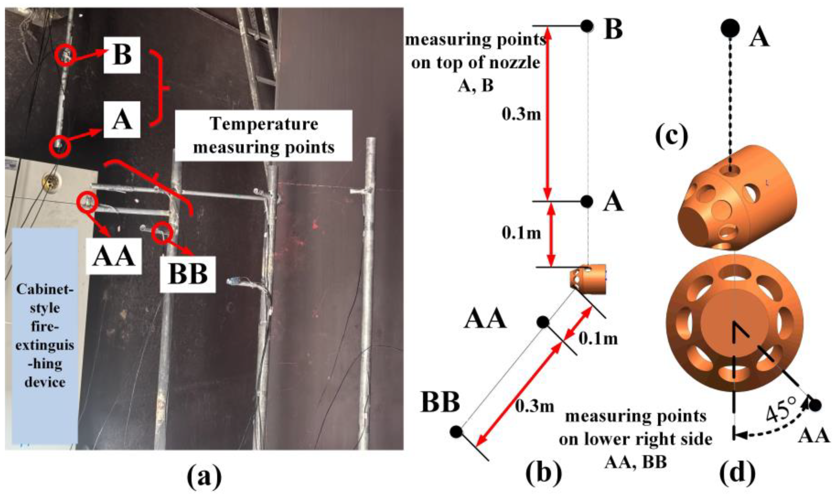
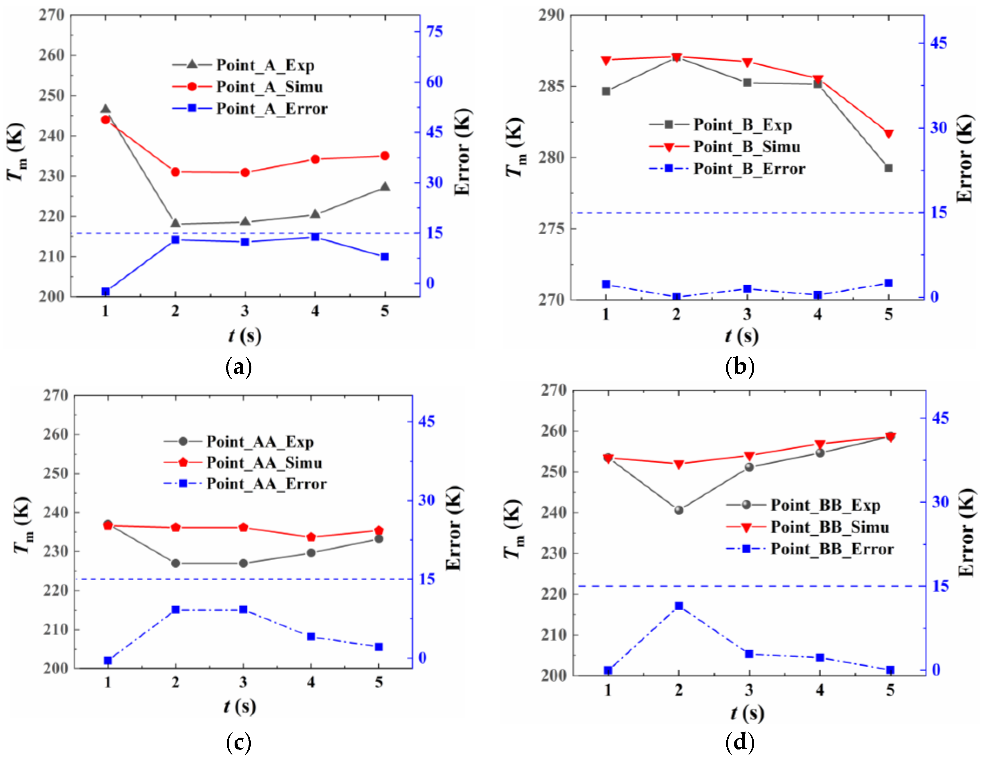
3.2. The Experimental Measurements and Numerical Method Validation

The temperature distribution of the protective room in the process of heptafluoropropane spraying (i.e., step II) from the nozzle was investigated with no fire source through experimental measurements, in order to validate the numerical simulation. An experimental room was built to test the vaporization and cooling performance of heptafluoropropane. Figure 4 shows the experimental gas fire-extinguishing device using heptafluoropropane and the measurement instruments. The nozzle is installed on top of the fire-extinguishing device. The dimensions of the protective room and the nozzle are listed in Table 1. The thermocouples measure the temperature changes caused by the spraying process of heptafluoropropane, which are arranged perpendicular to the normal line of the nozzle hole. The K-type thermocouple was selected, with a range of −80 to 200 °C and an accuracy of ±1.5 °C. Figure 5 shows the measuring points of the thermocouples, labeled as points A, B, AA, and BB. Points A and B are located above the nozzle perpendicularly, as shown in Figure 5c, while points AA and BB are located on the lower right side of the nozzle along the normal direction of the small hole with an angle of 45°, as shown in Figure 5d. The distance between the small holes and points A and AA are 0.1 m. The distance between points A and B, as well as that for points AA and BB, is 0.3 m.
The temperature variations in the protective room during the release of heptafluoropropane were compared with the numerical simulations. Figure 6 shows the comparison for points A, B, AA, and BB, where the expression of “Exp” and “Simu” represent the experimental and numerical results, respectively. The results illustrate that, as the release time increases, the temperatures at points A and AA present sudden drops. At point A, the temperature falls to the lowest value of 218.15 K, while that for point AA is 226.85 K. Subsequently, the temperatures at points A and AA increase slowly. The temperature at point B decreases from 286.15 K to 279.15 K, while that at point BB it increases from 238.15 K to 253.15 K. The variation in the numerical data presented similar trends as the experimental measurements. The absolute error between the numerical and experimental measurements was less than 15 K. Since the temperature of all measuring points was above 220 K, the value of the absolute error was relatively small which verified the numerical method. There are two main reasons for these errors. One is the assumptions in the numerical model, which lead to certain differences with respect to the actual release process. The other reason is the disturbance of fluid flow during the release of heptafluoropropane, which might affect the temperature measurements.

4. Results of the Vaporization and Fluid Flow Performance of Heptafluoropropane Spraying

The numerical simulation of heptafluoropropane spraying comprised two parts: its release in the fire cabinet (step I) and spraying from the nozzle (step II). Analysis of the first step was performed to obtain the mass ratio of the liquid phase, gas phase, and outlet velocity, which were then used as the boundary conditions in the second step. The analysis of the second step focused on the vaporization performance, temperature and velocity variations, and sudden cooling effect associated with heptafluoropropane spraying.

4.1. Heptafluoropropane Release in the Fire Cabinet

In the first step, the liquid heptafluoropropane with ratio of 100% is released from the fire cabinet in the numerical model, as depicted in Figure 2b. The mass flow rate and pressure difference were set to 6.5 kg and 0.5 MPa, respectively. As the pressure of the heptafluoropropane decreases, the liquid phase is converted into gas phase due to thermodynamic properties [48]. Here, the multi-phase model and time step were selected as the Eulerian method and 5 × 10⁻⁵ s, respectively. The variation in the mass ratio for the two phases and outlet velocity are illustrated in Figure 7, where g and l represent the gas and liquid phase, respectively. From the figure, it is obvious that the liquid phase decreased sharply and then increased to a certain value, while the gas phase presented an opposite trend. Figure 8a,b show the symmetric slices of mass ratio and velocity distribution. The contours illustrate that the velocity of working fluid increased from 6 to 30 m/s. The mass ratios of gas and liquid phases from the inlet to outlet illustrate the variation in Figure 7a. The mass ratios of the liquid phase, gas phase, and outlet velocity are listed in Table 4, which were used as the known parameters in step II.

4.2. The Vaporization of Heptafluoropropane from the Nozzle to Protective Room

Based on the numerical results for liquid heptafluoropropane released in the first step (Section 4.1), the mass ratio of the liquid phase to gas phase at the nozzle outlet was set as 20.2%. The total mass of the liquid and gas phases was 65 kg and the release time was 10 s. For the liquid phase, the DPM was applied in for the vaporization of heptafluoropropane, with the mass flow rate and initial temperature set as 1.31 kg/s and 256.65 K, respectively. The mass flow rate through the small holes pks, pkz, and pkx were set as 0.36 kg/s, 0.88 kg/s, and 0.07 kg/s, respectively. The diameter of the DPM particles was set as 0.0005 m. For the gas phase, the holes in the nozzle were set as the inlet velocity boundary condition with a value of 29.0 m/s. These are the known parameters for the second step of the vaporization process in the simulation. Temperature, concentration, and velocity variations were analyzed to improve the vaporization performance of the heptafluoropropane spraying system.

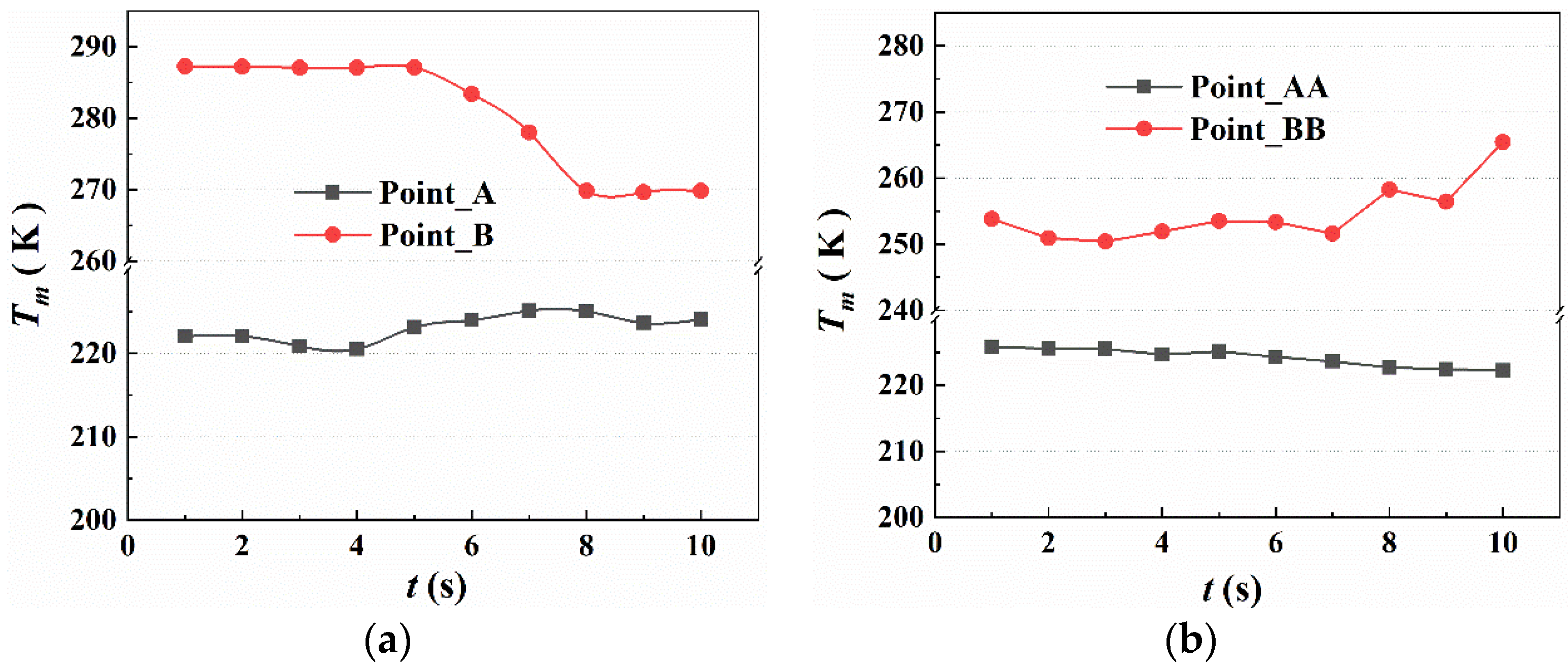
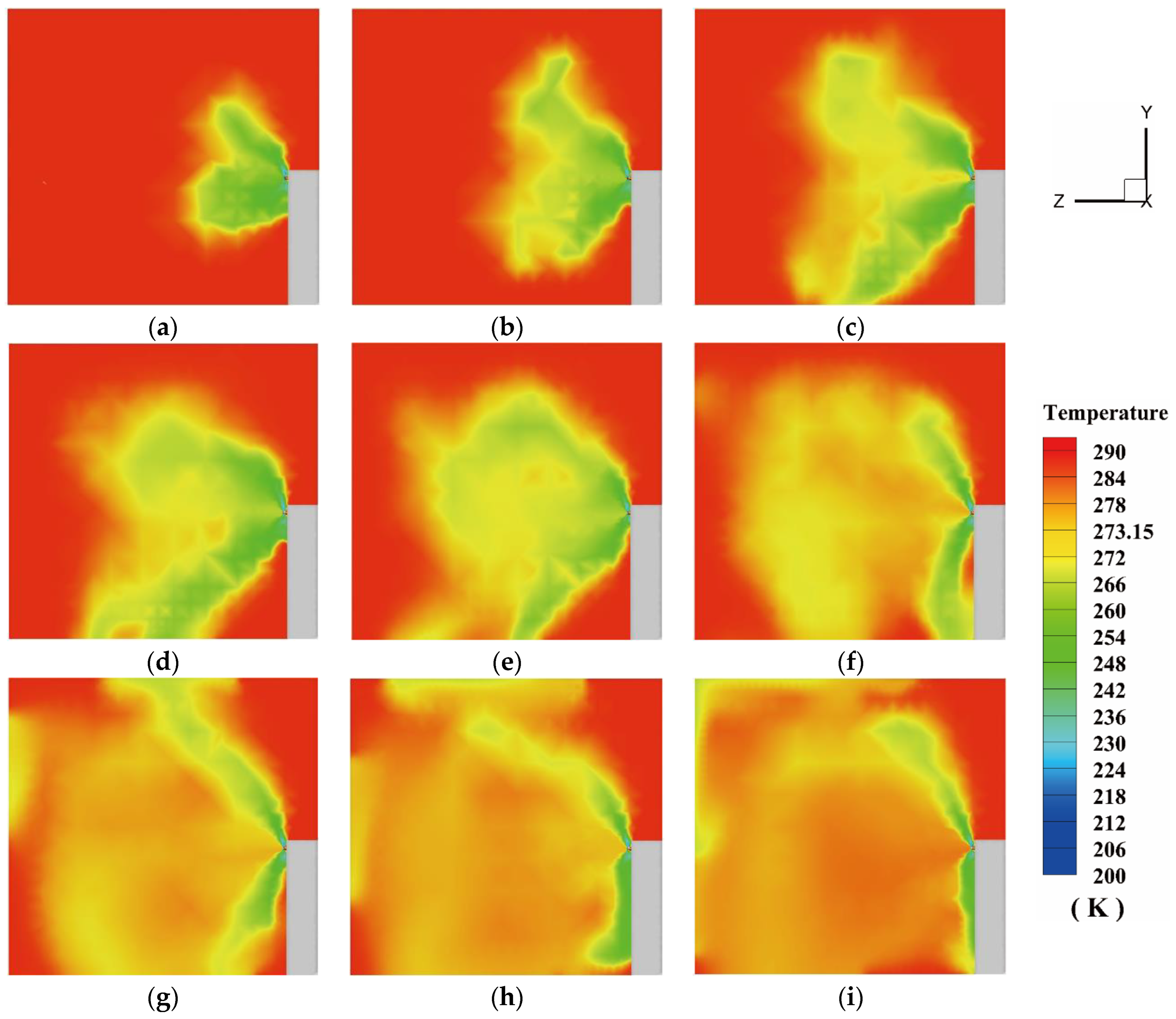
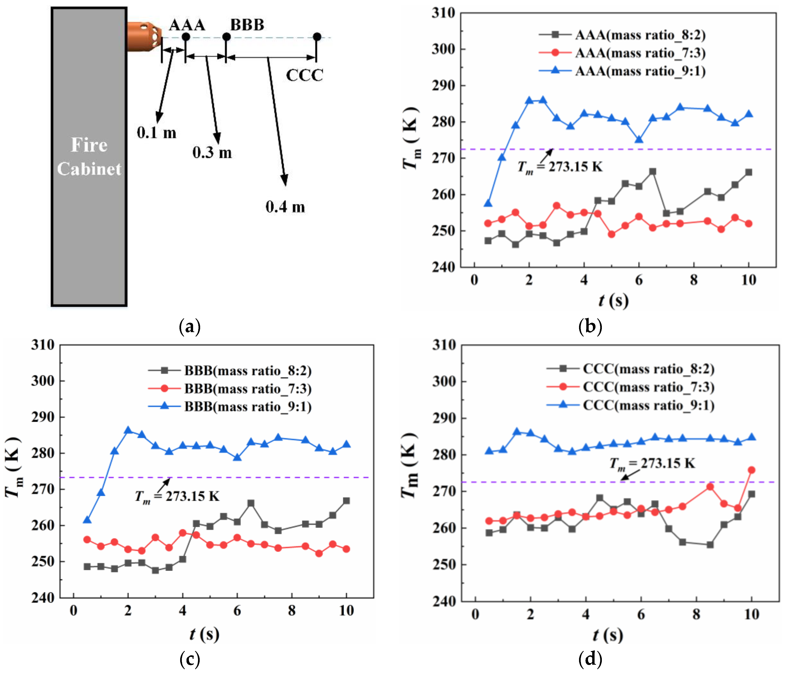
4.2.1. The Temperature Variation of the Protective Room

The temperature variations at different positions in the normal direction of the small holes on the nozzle are illustrated in Figure 9. The points A, B, AA, and BB were positioned as shown in Figure 5. As the spraying time varied from 0 s to 10 s, the temperature at the distance of 0.1 m from the nearest small hole presented a sharp decrease to 220 K (i.e., −53 °C). The temperature at points A and AA were nearly the same after 10 s. The temperature variations at points B and BB presented different trends with heptafluoropropane spraying. When t varied from 0 to 5 s, the temperatures at points B and BB remained almost unchanged (287 K and 250 K, respectively). Then, the temperature at point B decreased to 270 K, while that at point BB increased to 265 K. This phenomenon shows that the temperature drop on top of the nozzle has a delay due to the fluid flow of heptafluoropropane spraying.
The positions of sections for analysis of the 2D temperature and streamline fields are shown in Figure 10. The sections consist of the vertical symmetric plane and horizontal plane, characterized by X = 0 m and Y = 1.925 m, respectively. The display range of the vertical and horizontal planes are 4.72 m × 4.5 m and 4.72 m × 4.72 m, respectively.
Figure 11 displays the temperature variation in the vertical symmetric plane of the protective room. The red region represents the initial temperature of ambient air, which is 287.25 K. The heptafluoropropane sprays from the small holes and absorbs a large amount of heat, which causes a cooling effect in the surrounding area. The green and yellow regions represent the sudden cooling effect, where the lowest temperature reached 230 K. At the beginning of spraying, the low-temperature region appears in the forward direction of the eight holes in the nozzle, which indicates the release direction of the heptafluoropropane. As the spraying time t increases to 4 s, the average temperature in the middle region in the protective room is decreased. The upward spray of heptafluoropropane starts to settle due to the gravity, following which the heptafluoropropane diffuses to the ground or other areas. When the spraying time reached 8 s, the temperature of the majority of the area in the vertical plane had decreased, varying from 272 K to 284 K. With increasing spraying time, the temperatures at points B and BB are slightly affected by the heptafluoropropane spraying, due to the effects of gravity and the fluid flow. These phenomena verify the results shown in Figure 9 and indicate that heptafluoropropane spraying from the nozzle of the fire cabinet can quickly reduce the average temperature distribution in the protective room, thus achieving fire suppression.
Figure 12 shows the temperature contour in the horizontal plane based on the central axis of the nozzle. The results illustrate that heptafluoropropane spraying from the symmetrical small holes has a similar cooling effect on the protective room. When the heptafluoropropane starts to spray, the temperature of the area facing the fire cabinet in the direction of the axis of the nozzle decreases first. As the release time reaches 4 s, the diffused gaseous heptafluoropropane accumulates in the middle of the protective room, which corresponds to the results shown for the vertical symmetric plane. The opposite wall from the fire cabinet is cooled due to the fluid flow of heptafluoropropane at 7 s. Therefore, the high-pressure spraying of heptafluoropropane from the prefabricated fire-extinguishing device can reduce the surrounding temperature from the middle to the edge of the protective room.

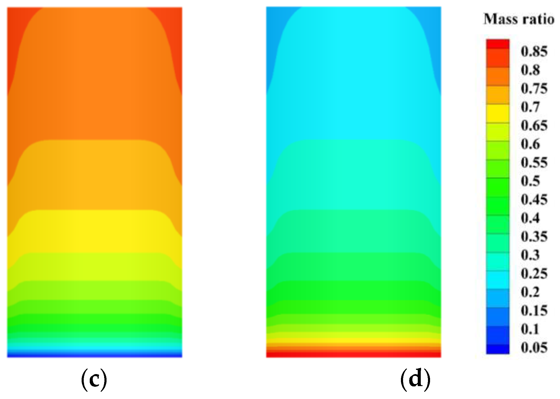
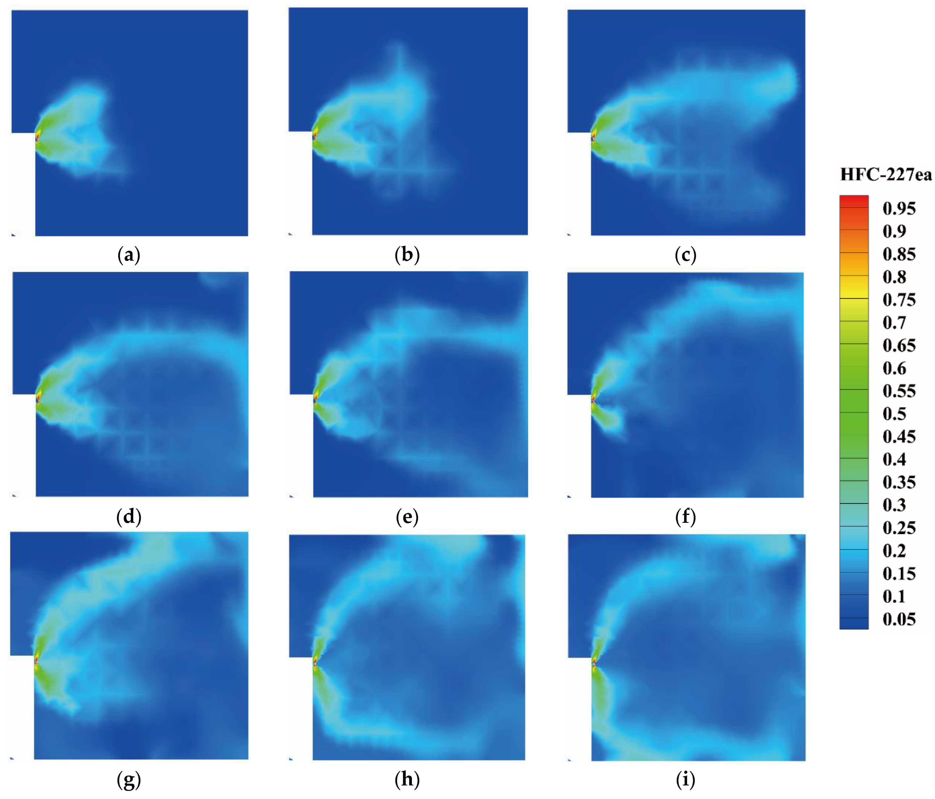
4.2.2. The Concentration Variation of Heptafluoropropane in the Protective Room

In order to analyze the concentration distribution of heptafluoropropane, the iso-surfaces of mass fraction of 0.1 in the spraying process were obtained, as shown in Figure 13. The velocity contours are also illustrated on the iso-surfaces in order to assess the fluid flow performance. After the heptafluoropropane starts to spray from the nozzle, the vaporized fluid accumulates in the middle of the protective room, as shown in Figure 13a,b, with the velocity varying between 1.2 and 2.8 m/s. As the spraying time t increases, the heptafluoropropane diffuses to the wall opposite to the fire cabinet and the average velocity starts to decrease. After the spraying time t reaches 6 s, the heptafluoropropane gradually fills the entire protective room and part of the gas phase settles to the bottom.
Figure 14 shows the mass fraction variation of the heptafluoropropane in the vertical symmetrical plane. The results illustrate that the vaporized heptafluoropropane quickly moves in front of the nozzle within 2 s. Then, the heptafluoropropane flows to the opposite side and settles down from 3 s to 6 s, which corresponds to the phenomenon shown in Figure 13d–f. After the spraying time t reaches 8 s, the top and bottom of the protective room are partially covered by heptafluoropropane. The concentration variation is also shown in the video in the Supplementary Materials (Video S1).

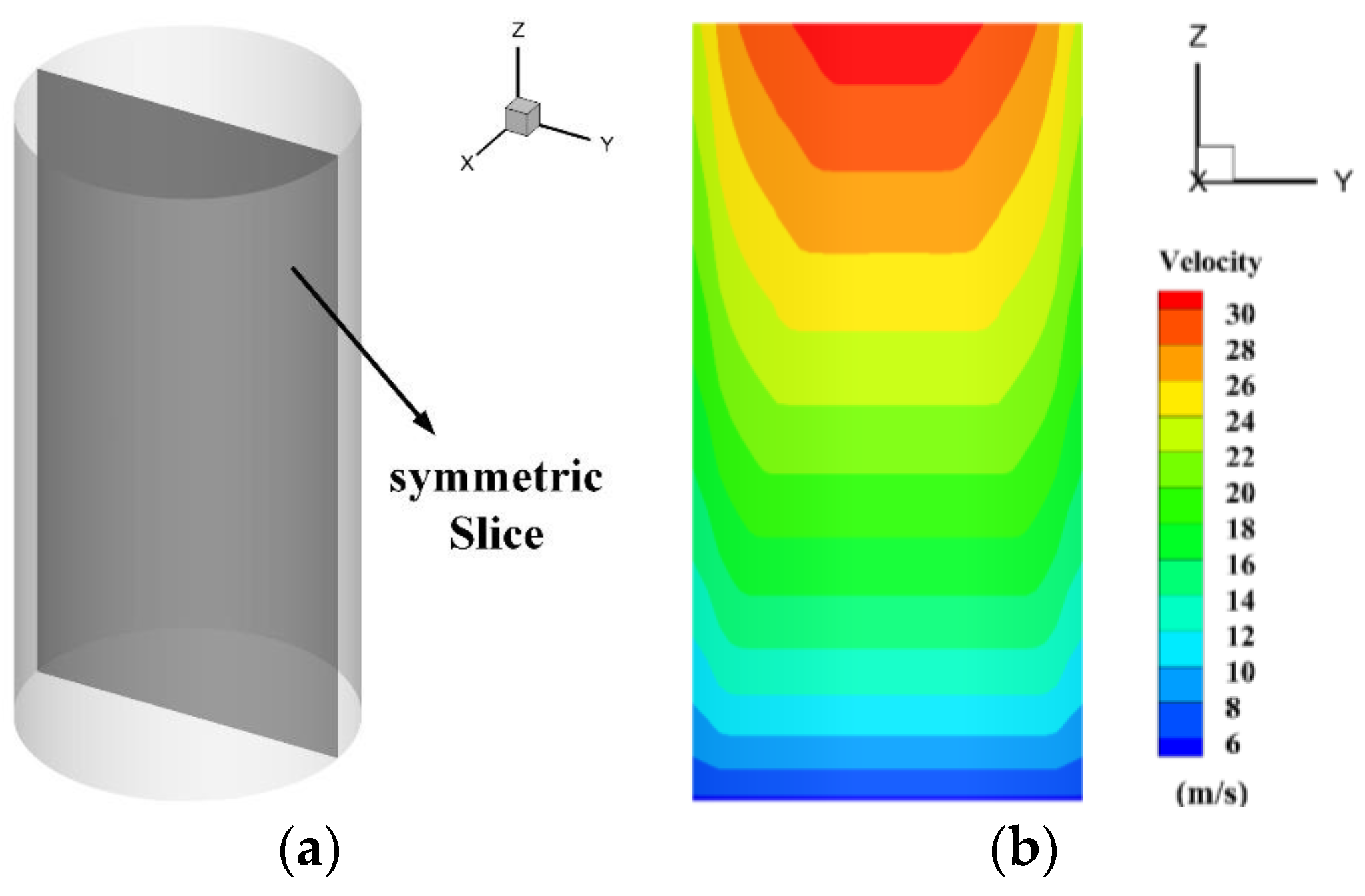
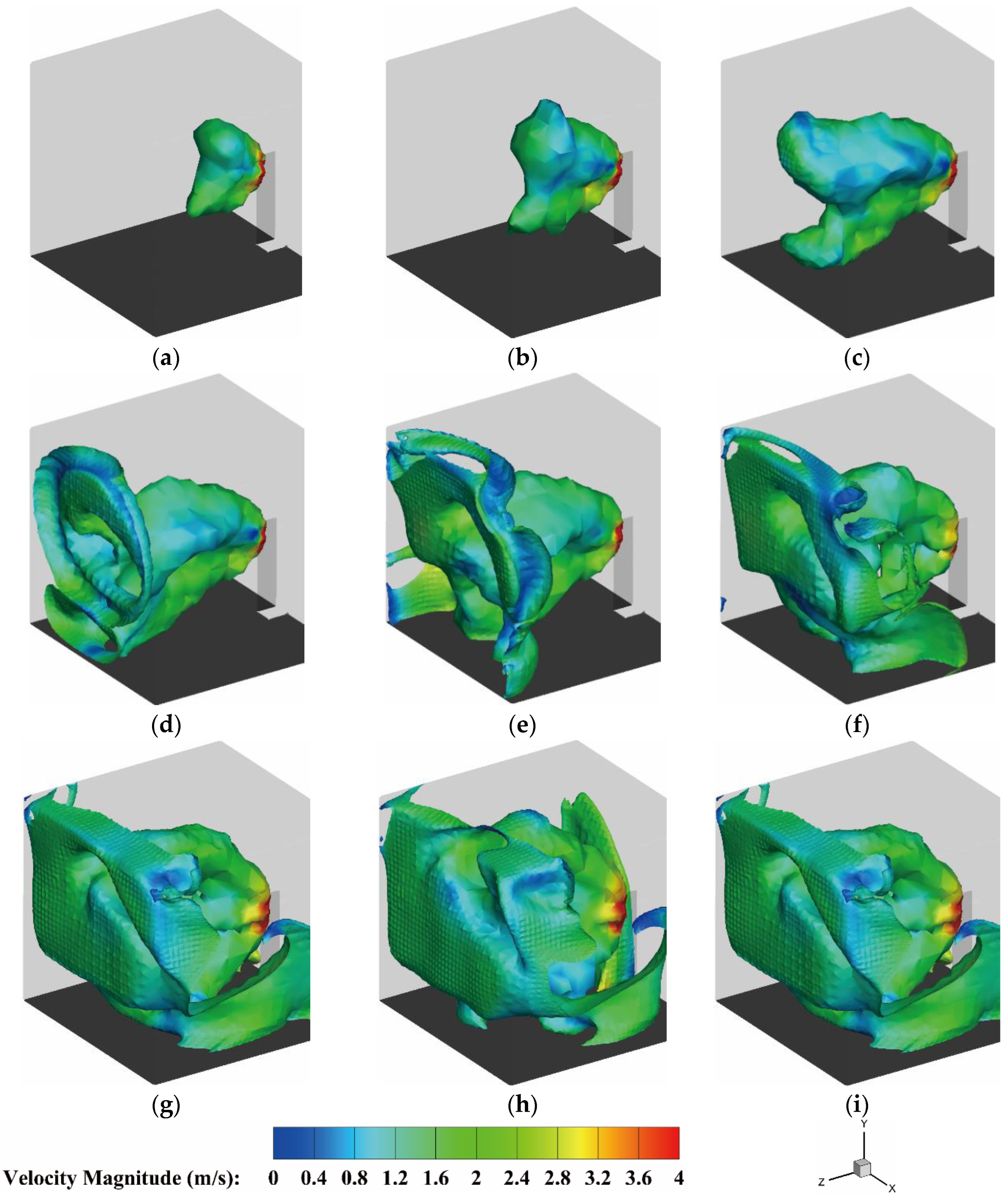
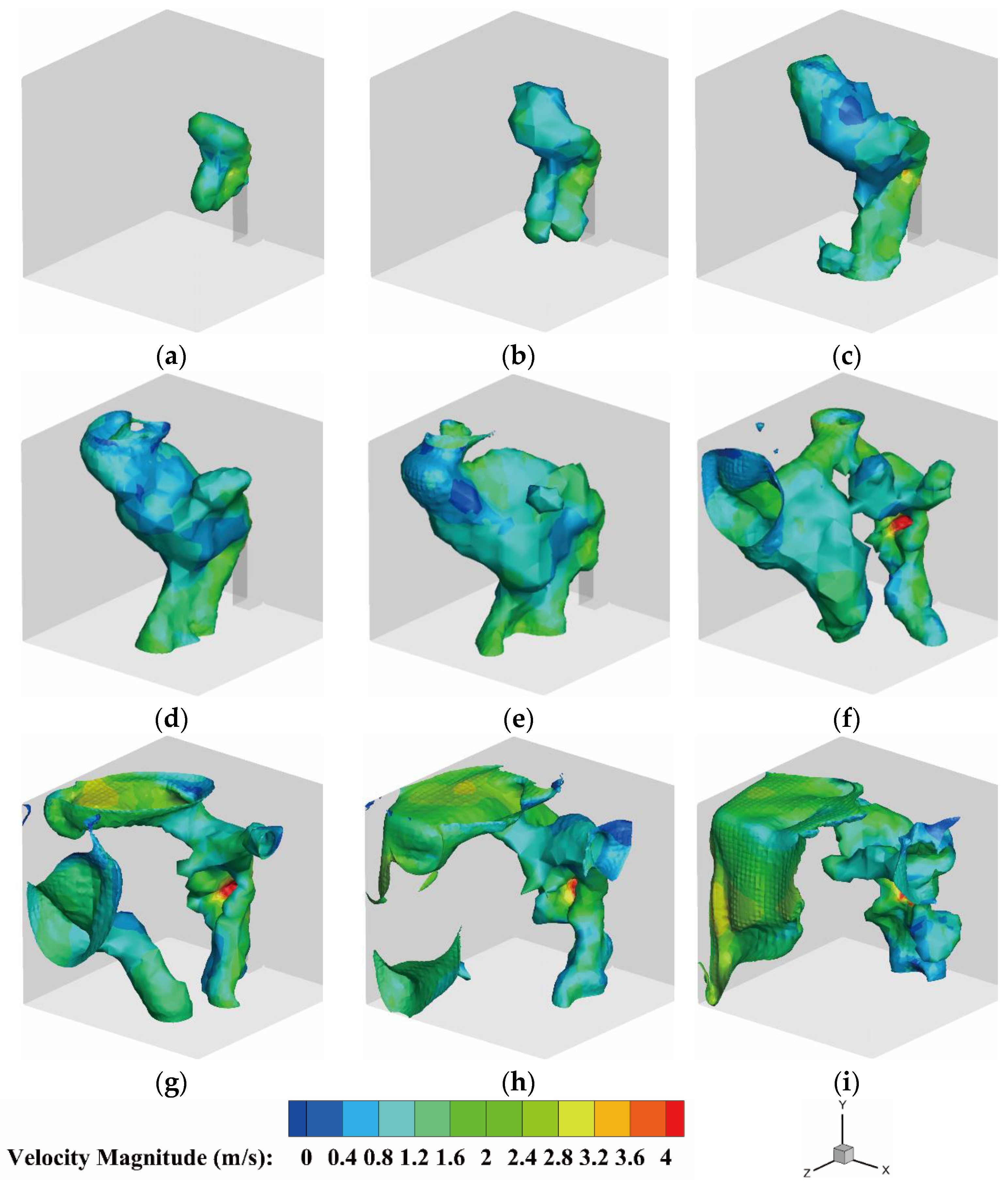
4.2.3. The Velocity Distribution of the Heptafluoropropane in the Protective Room

In order to analyze the spraying process in the protective room, the velocity distribution and streamlines of heptafluoropropane are displayed in Figure 15 and Figure 16. Figure 15 shows the velocity variations on the iso-surface distribution of T = 273.15 K, which also reflects the trend of iso-surface expansion. At 1 s, the gas phase of heptafluoropropane releases from small holes in the nozzle, with the velocity varying from 1.6 to 2.8 m/s. Then, the heptafluoropropane diffuses along the normal direction of the small holes to the top and bottom of the protective room during the spraying time of 2.0–4.0 s. The flowing gas phase gathers into clusters in front of the fire cabinet at 4.0 s. In the spraying time from 5.0 to 8.0 s, the area with temperature of 273.15 K continues to develop near the walls. Compared with the velocity variation shown in Figure 13, the iso-surfaces in Figure 15 illustrate the trend of the temperature reaching 273.15 K due to the diffusion of heptafluoropropane. The heptafluoropropane accumulates in the protective room and the temperature in the high-concentration area drops to 273.15 K or lower. These phenomena confirm the sudden cooling effect caused by heptafluoropropane spraying from the prefabricated fire-extinguishing device.
Figure 16 presents the streamlines and contours of the velocity field in the spraying process of heptafluoropropane from t = 0.5 s to 7 s, illustrating the relationships among the vortices, streamlines, and velocity distribution. As t varies from 0.5 s to 2 s, a large eddy forms along the tangential direction of heptafluoropropane spraying, where the velocity of gas phase reaches about 2.8 m/s. The eddy continues to develop and vanishes at the time of 3.0 s, at which point the vortex compresses into a flattened structure. When t varies from 4.0 s to 7.0 s, the large eddy regenerates at the top of the protective room due to the velocity gradient. Back flow of the heptafluoropropane will occur in front of the fire cabinet, near the bottom. The velocity in the region in front of the nozzle is relatively lower than that in the normal direction of the small holes. The high-velocity regions occur on the flow path of the heptafluoropropane sprays. Through analyses of the streamlines and velocity distribution, the results reflect that the gas-phase heptafluoropropane is sprayed out along the normal direction of the small holes on the nozzle under certain initial conditions in terms of pressure and velocity, allowing the working fluid to cover most regions in the protective room.

4.2.4. The Cooling Effect and Safe Distance of the Heptafluoropropane Spraying

In order to obtain the recommended safe distance settings under various conditions of heptafluoropropane spraying, the cooling effect and temperature variations under different mass ratios of the liquid and gas phases were analyzed. Figure 17 shows the temperature variation at three positions along the nozzle axis, where AAA, BBB, and CCC represent positions at distances of 0.1 m, 0.4 m, and 0.8 m along the axis, respectively. The mass ratio conditions of the gas and liquid phases consist of 8:2, 9:1, and 7:3. The purple dotted lines denote the areas where the temperature is 273.15 K. From Figure 17b–d, it is evident that the temperatures at the three positions are over 280 K (i.e., above 0 °C) under the condition of a mass ratio of 9:1. When the mass ratio of the gas and liquid phases is 8:2, the temperatures at points AAA and BBB first decrease to 250 K and increase slowly after 4 s, while that at CCC fluctuates around a value of 260 K. The temperatures at AAA and BBB are relatively lower than those under other conditions with a mass ratio of 7:3. These phenomena illustrate the temperature change in front of the fire cabinet during heptafluoropropane spraying and provide guidance for the installation and operational design of fire-extinguishing equipment.
Figure 18 shows the temperature variation at four points under the mass ratio conditions of 9:1 and 8:2, where the positions of points A, B, AA, and BB are as shown in Figure 5. The point CC is on the extensive line of AA and BB and is at a distance of 0.8 m from the nozzle hole. Figure 18a illustrates that the temperatures at points A and B under a mass ratio of 9:1 were higher than those with a mass ratio of 8:2 at 10 s. The variation also indicated that heptafluoropropane spraying has little cooling effect on the area at the top of the nozzle past 0.4 m. Figure 18b demonstrates the temperatures of points AA, BB, and CC versus spraying time. It is clearly seen that the temperatures at point CC are higher than those at points AA and BB as the time progresses. The temperatures at point CC under mass ratios of 9:1 and 8:2 remained at values of 280 K and 270 K, respectively. As the overall spraying time was 10 s, the cooling performance is considered to have little effect on the protective equipment. Therefore, a distance of 0.8 m in front of the nozzle under different mass ratios can be considered as a reference value for the safe distance due to the relatively small cooling effect, which can help to protect the electrical equipment in rooms equipped with the considered prefabricated gas fire-extinguishing system.

5. Discussions on the Cooling Effect of Prefabricated Fire-Extinguishing Device in the Fire Suppression Process

5.1. The Heat Transfer Rate of the Fire Source and Experimental Validation

To analyze the cooling effect of the considered device in the context of fire suppression, the fire source was investigated through numerical simulation and experimental measurements. The fire source was wood stack burning, which is considered to be a Class A fire. The flame height of the wood stack fire is relatively high and the heat release rate has been obtained through analyses of experimental and numerical results [37]. In this work, the heat release rate of the fire source was determined based on the temperature measurements in the upper region, as shown in Figure 19, which shows the locations and dimensions of the temperature measurement points and fire source. The support for seven measurement points is located along the diagonal of the protective room. The symmetric centerline coincides with that of the fire source. Seven thermocouples are distributed at different heights on the support. Figure 19b shows a view of the support plane. The dimensions between the measurement points and the fire source, as well as the adjacent points, are marked on the figure.
In the experiments, the temperatures at the six points were measured with K-type thermocouples for 10 s after the fire source had been placed. Figure 20 shows the temperatures at the measuring points and absolute errors obtained from three tests. The results illustrate that the temperatures at the six points were similar to those in tests 2 and 3. The absolute errors at each point were less than 8 K. In the numerical simulation, the protective room shown in Figure 2a was heated by a fire source to obtain the corresponding temperatures at the measurement points. With the heat release rate of the fire source was set to 30 KW/m2, the comparison results for the six points are listed in Table 5.
The results illustrate that the temperatures at measurement points of 5 and 7 were over 370 K, while those at other points were below 300 K. The maximum absolute error was less than 7 K, thus verifying the settings for the fire source. Table 6 lists the numerical results for the wood stack fire. As the area of the fire source on top of the support base is 0.125 m2, the heat flux is 3750 W. These results were used as the initial conditions for further analyses of heptafluoropropane spraying for the purpose of fire suppression.

5.2. The Temperature Variation in the Fire Suppression

After the protective room had been heated by the fire source for 10 s, the heptafluoropropane (from the I step) started to spray from the nozzle and cool down the surrounding area. Figure 21 shows the temperature variations at eight points in different directions during the heptafluoropropane spraying process. Figure 21a,b illustrate that the temperatures at points A and AA were lower than the others, while those at points B and BB reached about 250 K. When the heptafluoropropane spraying was complete at the time of 10 s, the temperatures at the measurement points rose quickly to the certain value of 270 K. For points AAA, BBB, and CCC, the trend of temperature variation remained almost the same. The temperatures at points BBB and CCC first increased to 295 K, then decreased to 270 K by 12 s. Furthermore, the temperature at point AAA presented a rapid decrease to 260 K at 10 s. Therefore, the temperatures of regions in the direction of the nozzle holes decreased rapidly as the fire-extinguishing process continued, thus causing the cooling effect. The temperatures were ultimately maintained at 270 K at distances of 0.4 m and 0.8 m along the nozzle axis. Figure 22 shows the temperature contours in the vertical symmetric plane with spraying time t from 0 to 7 s. The fire source is extinguished within 4 s and deviates towards the nozzle position. From 2 s to 7 s, the lower-temperature region develops on the bottom as the heptafluoropropane settles and accumulates in the protective room. After the fire is extinguished, the temperature distribution throughout the entire room gradually becomes uniform.

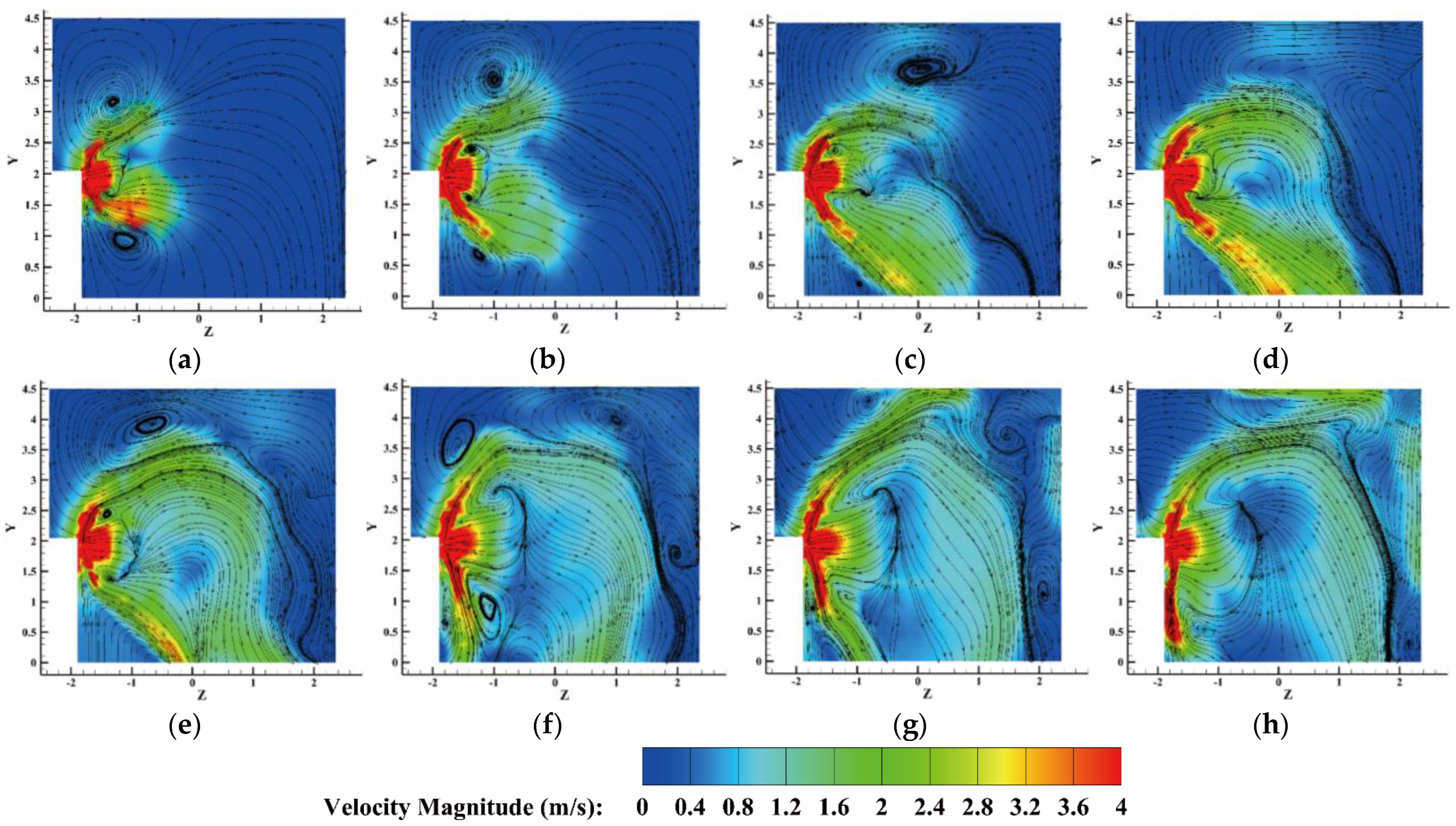
5.3. The Velocity and Concentration Distribution in the Fire Suppression Process

Figure 23 shows the velocity distribution and streamlines in the vertical symmetric plane throughout the whole process of heptafluoropropane spraying. At the starting time, the protective room is heated by the fire source, which forms a circulation flow from the center to both sides. When the heptafluoropropane starts to spray at the time of 1 s to 2 s, a high-velocity region forms in the normal direction of the nozzle holes and several vortices occur in the tangential direction of the upper and lower zones near the fire cabinet. Due to the influence of the heated air flow, the position and high-velocity regions significantly differ from those when spraying with no fire (as shown in Figure 16). Then, the vortex continues to develop on top of the nozzle and the velocity of the fluid flowing along the nozzle axis gradually increases from 4 s to 10 s. After heptafluoropropane spraying is completed, the fluid velocity decreases rapidly in the protective room. Therefore, heptafluoropropane is sprayed at high speed in the protective room to form a large vortex or reflux, absorbing a significant amount of heat to achieve a local sudden drop in temperature for the purposes of extinguishing the fire.
The mass fractions of heptafluoropropane for the eight points in different positions with increasing spraying time are shown in Figure 24. The points A and AA have higher mass fractions at 10 s, compared with the others, with a maximum value of 0.5. The maximum mass fraction at points B and BB reached 0.3. For the three points along the nozzle axis, the mass fraction of heptafluoropropane increased rapidly to 0.12 between 5 s and 10 s. The maximum value of the mass fraction (i.e., 0.22) occurred at point AAA. Then, the mass fraction of heptafluoropropane gradually increased slowly. Therefore, the heptafluoropropane sprayed out in the protective room with a maximum mass fraction of 0.5. When the spraying process was complete, the concentration of the mass fraction still remained at a value of 0.1 at a distance of 0.8 m from the nozzle axis, indicating the uniform distribution of heptafluoropropane in the protective room, thus promoting its fire-extinguishing performance while protecting electrical equipment. The dynamic process of concentration variation with fire source is also shown in a video provided in the Supplementary Materials (Video S2).

6. Conclusions

In this work, we proposed a numerical simulation model to analyze the vaporization and cooling performance of heptafluoropropane, used in a prefabricated fire-extinguishing device. The vaporization process of heptafluoropropane involves the release of liquid heptafluoropropane from the fire cabinet to the nozzle (step I) and spraying of the mixture phase from the nozzle (step II). Experimental measurements of heptafluoropropane vaporization with no fire source were carried out to verify the numerical simulation. It was shown that heptafluoropropane spraying can quickly reduce the average temperature distribution throughout the protective room, leading to a sudden cooling effect. The cooling effect and the temperature variations under different mass ratios of the liquid and gas phases were analyzed to obtain the safe distance between the nozzle and the protected equipment. The findings provide significant insights into the vaporization mechanism of heptafluoropropane with and without a fire source. The main conclusions are as follows:
(1)
A numerical simulation model was established based on the phase change and fluid flow process. The release of heptafluoropropane from the cabinet and its spraying from the nozzle were analyzed based on Eulerian and DPM models, respectively. The results indicated that the vaporization of heptafluoropropane in the cabinet presents certain differences with that relating to its spraying from the nozzle. The numerical method was validated through experimental temperature comparisons and can help to improve the vaporization performance of heptafluoropropane.
(2)
For heptafluoropropane spraying without a fire source, analysis of its release in the fire cabinet (step I) illustrated that the velocity, liquid, and gas phases of heptafluoropropane are 29.0 m/s, 20.2%, and 79.8%, respectively. These results reflect the fact that the heptafluoropropane is a mixture of gas and liquid phases during the spraying process, although its boiling point is 256.75 K. The sudden cooling effect will occur with the lowest temperature of 220 K, which can contribute to its concentration and velocity distribution in the protective room. Analysis of the vaporization process indicated that a distance of 0.8 m in front of the prefabricated fire cabinet can serve as a reference value for the safe distance. The heptafluoropropane was shown to gradually fill the entire room, with part of the gas phase settling at the bottom.
(3)
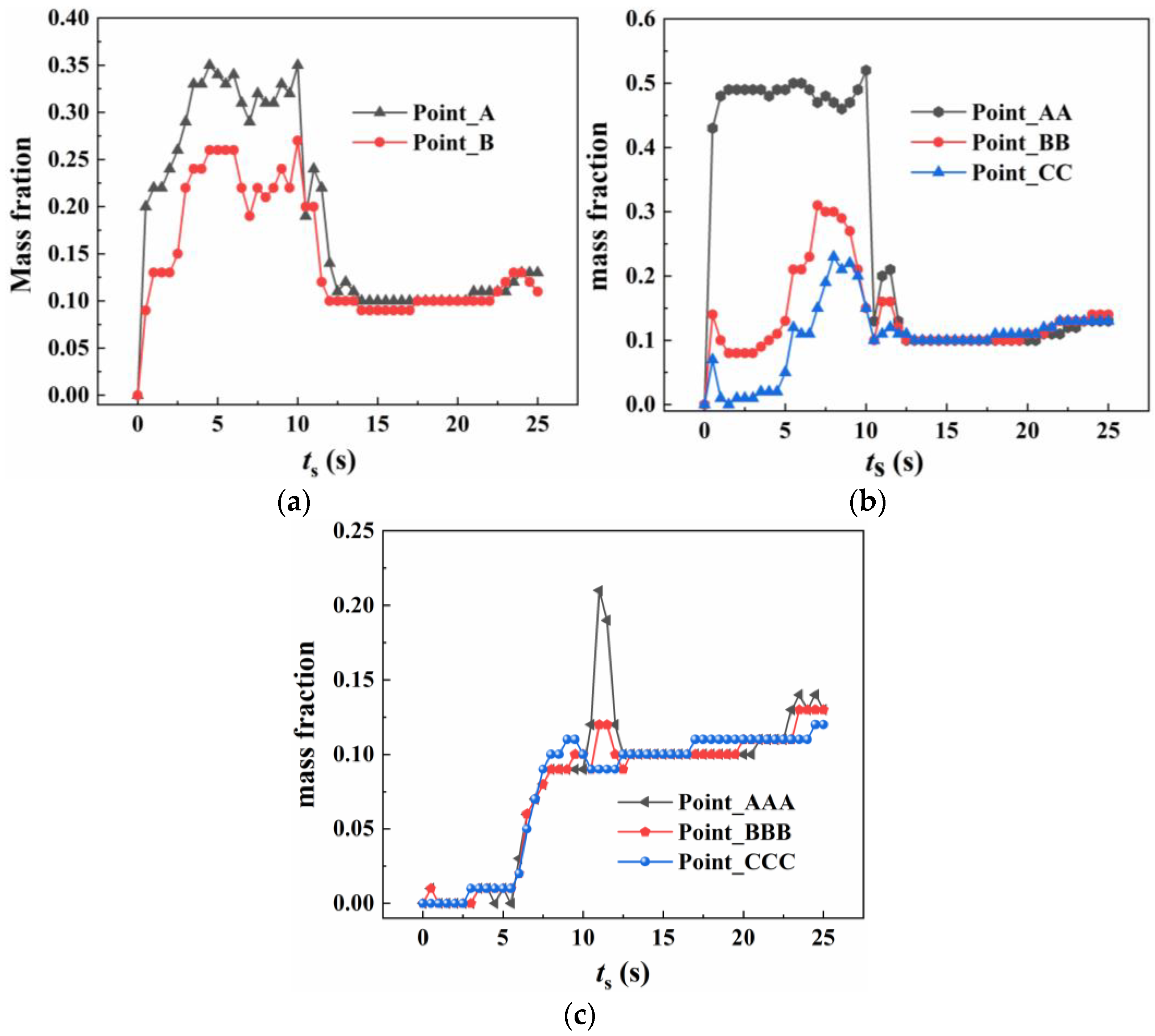
For heptafluoropropane spraying with a fire source, an actual fire-extinguishing scenario with a wood stack fire was assessed through experiments and simulations. A large vortex was formed, helping to achieve a sudden temperature drop, due to the high speed of heptafluoropropane spraying. The concentration at a distance of 0.8 m from the nozzle remained at a mass fraction of 0.1. Furthermore, the uniform distribution of heptafluoropropane is beneficial in terms of fire-extinguishing performance as well as the protection of electrical equipment. The results obtained offer guidance for the design of prefabricated fire-extinguishing systems using various mass ratios regarding heptafluoropropane vaporization.

Supplementary Materials

The following supporting information can be downloaded at: https://www.mdpi.com/article/10.3390/fire8040124/s1, Video S1: mass fraction-1-no fire source; Video S2: mass fraction-2-with fire source.

Author Contributions

Conceptualization, W.-B.Z. and Q.Y.; methodology, W.-B.Z., M.-R.L. and Q.Y.; software, M.-R.L. and Q.Y.; validation, W.-B.Z., Q.Y. and C.-Q.L.; formal analysis, W.-B.Z.; investigation, W.-B.Z. and Z.-C.W.; resources, W.-B.Z.; data curation, M.-R.L. and C.-Q.L.; writing—original draft preparation, W.-B.Z. and Q.Y.; writing—review and editing, Q.Y. and Z.-M.H.; visualization, Z.-M.H.; supervision, C.-Q.L. and Z.-C.W.; project administration, W.-B.Z. and Q.Y.; funding acquisition, W.-B.Z. and Q.Y. All authors have read and agreed to the published version of the manuscript.

Funding

This research was funded by the following projects: 1. National Key Research and Development Program Plan (Grant No. 2023YFC3010205-01); 2. The Open Project of the Key Laboratory of Fire Protection Technology for Industry and Public Building, Ministry of Emergency Management (Grant No. 2023KLIB05); 3. Tianjin Science and Technology Plan Project (Grant No. 22JCZDJC00860); 4. National Key Research and Development Program Project (Grant No. 2023YFC3010205); 5. National Natural Science Foundation of China (Grant No. 52376137); 6. Basic Research Special Fund Project for Central Public Welfare Research Institutes (Grant No. 2024SJ16).

Institutional Review Board Statement

Not applicable.

Informed Consent Statement

Not applicable.

Data Availability Statement

Data are available upon request.

Conflicts of Interest

The authors declare no conflicts of interest.

References

  1. Sanli, E.A.; Brown, R.; Simmons, D. A Pilot Study to Assess the Feasibility of Comparing Ultra-High Pressure to Low-Pressure Fire Suppression Systems for a Simulated Indirect Exterior Attack. Fire 2023, 6, 278. [Google Scholar] [CrossRef]
  2. Coulombe, R.G.; Rao, A. Fires and local labor markets. J. Environ. Econ. Manag. 2025, 130, 103109. [Google Scholar] [CrossRef]
  3. Gaidukova, O.; Misyura, S.; Donskoy, I.; Morozov, V.; Volkov, R. Pool Fire Suppression Using CO2 Hydrate. Energies 2022, 15, 9585. [Google Scholar] [CrossRef]
  4. Rohilla, M.; Saxena, A.; Tyagi, Y.K.; Singh, I.; Tanwar, R.K.; Narang, R. Condensed Aerosol Based Fire Extinguishing System Covering Versatile Applications: A Review. Fire Technol. 2021, 58, 327–351. [Google Scholar] [CrossRef]
  5. Marco, S.; Nicolo, T.; Luca, T.; Paolo, E. Experimental Assessment of the Acoustic Performance of Nozzles Designed for Clean Agent Fire Suppression. Appl. Sci. 2022, 13, 186. [Google Scholar] [CrossRef]
  6. Rocha, H.; Campos, T.; Gamboa, P. Design and analysis of air launched fire-extinguishing devices. CEAS Aeronaut. J. 2024, 15, 849–865. [Google Scholar] [CrossRef]
  7. Yang, K.; Miao, H.; Ji, H.; Chen, S.; Xing, Z.; Jiang, J.; Zheng, K.; Liu, G. Experimental study on the coupling effect of heptafluoropropane and different arrangement of obstacles on methane-air explosion. Fuel 2024, 358, 130204. [Google Scholar] [CrossRef]
  8. Higashi, Y.; Shima, K.; Suzuki, M.; Fujishiro, M.; Kawai, T.; Morimoto, T. Synthetic Utilization of 2H-Heptafluoropropane: Ionic 1, 4-Addition to Electron-Deficient Carbon–Carbon Unsaturated Bonds. J. Org. Chem. 2024, 89, 3962–3969. [Google Scholar] [CrossRef]
  9. Papas, P.; Cao, C.; Kim, W.; Baldwin, E.; Chattaway, A. Fire suppression using trifluoroiodomethane (CF3I)-carbon dioxide (CO2) mixtures. Proc. Combust. Inst. 2023, 39, 3765–3773. [Google Scholar] [CrossRef]
  10. Gaidukova, O.; Donskoy, I.; Misyura, S.; Morozov, V.; Volkov, R. The Interaction between a Liquid Combustion Front and a Fire Barrier Made of CO2 Hydrate. Fire 2023, 6, 124. [Google Scholar] [CrossRef]
  11. Liu, Z.; Zhu, Y.; Li, R.; Tao, C.; Chen, Z.; Liu, T.; Li, Y. The experimental investigation of thermal runaway characteristics of lithium battery under different concentrations of heptafluoropropane and air. J. Energy Storage 2024, 84, 110828. [Google Scholar] [CrossRef]
  12. García-Anteportalatina, V.M.; Martín, M. Process synthesis for the valorisation of low-grade heat: Geothermal brines and industrial waste streams. Renew. Energy 2022, 198, 733–748. [Google Scholar] [CrossRef]
  13. Cao, X.; Lu, Y.; Jiang, J.; Wang, Z.; Wei, H.; Li, Y.; Li, Y.; Lin, C. Experimental study on explosion inhibition by heptafluoropropane and its synergy with inert gas. J. Loss Prev. Process Ind. 2021, 71, 104440. [Google Scholar] [CrossRef]
  14. Ji, H.; Lu, R.; Yang, K.; Jiang, J.; Xing, Z.; Guo, J. Experimental study on methane explosion suppression by heptafluoropropane drived modified ABC powder. Process Saf. Environ. Prot. 2023, 170, 623–635. [Google Scholar] [CrossRef]
  15. Robin, M.L. Suppression of class a fires with HFC-227ea. Process Saf. Prog. 1998, 17, 209–212. [Google Scholar] [CrossRef]
  16. Roy, A.; Chawhan, R.S.; Patel, R.; Varadharajan, S.; Tiwari, L.M.; Chakraborty, A.L.; Ghoroi, C.; Srivastava, G. Quantifying the CO and CO2 Mole Fraction in the Plume of an Aerosol-Based Fire Extinguishing Agent Using 4560 nm and 4320 nm QCLs. IEEE Sens. J. 2019, 19, 9728–9735. [Google Scholar] [CrossRef]
  17. Wu, Y.; Yu, X.; Wang, Z.; Jin, H.; Zhao, Y.; Wang, C.; Shen, Z.; Liu, Y.; Wang, W. The flame mitigation effect of N2 and CO2 on the hydrogen jet fire. Process Saf. Environ. Prot. 2022, 165, 658–670. [Google Scholar] [CrossRef]
  18. Aydin, M. An analysis of human error and reliability in the operation of fixed CO2 systems on cargo ships using HEART Dempster-Shafer evidence theory approach. Ocean. Eng. 2023, 286, 115686. [Google Scholar] [CrossRef]
  19. Tanaka, F.; Kato, D. Experimental and numerical study on fire extinguishing by water spray. Fire Saf. J. 2023, 141, 103984. [Google Scholar] [CrossRef]
  20. Xiao, T.; Gupta, V.; Dunn, M.J.; Masri, A.R. Joint OH-PLIF and Mie scattering imaging of enhanced water mist suppression of buoyant fires. Proc. Combust. Inst. 2024, 40, 105331. [Google Scholar] [CrossRef]
  21. Zhdanova, A.O.; Volkov, R.S.; Voytkov, I.S.; Osipov, K.Y.; Kuznetsov, G.V. Suppression of forest fuel thermolysis by water mist. Int. J. Heat Mass Transf. 2018, 126, 703–714. [Google Scholar] [CrossRef]
  22. Ma, L.; Fan, J.; Guo, R.Z.; Zhang, P.Y.; Li, C.H. Characteristics of fires in coal mine roadways and comparative analysis of control effectiveness between longitudinal ventilation and cross-section sealing. Case Stud. Therm. Eng. 2024, 53, 103878. [Google Scholar] [CrossRef]
  23. Nikam, P.C.; Rao, A.R.; Shertukde, V.V. Effect of polyethylene terephthalate fiber reinforced with non-hydrophilic nano-silica on the mechanical, thermic, and chemical shielding characteristics of saturated polyurethane composite. J. Appl. Polym. Sci. 2022, 140, e53334. [Google Scholar] [CrossRef]
  24. Baalisampang, T.; Saliba, E.; Salehi, F.; Garaniya, V.; Chen, L. Optimisation of smoke extraction system in fire scenarios using CFD modelling. Process Saf. Environ. Prot. 2021, 149, 508–517. [Google Scholar] [CrossRef]
  25. Bolshova, T.A.; Shvartsberg, V.M.; Shmakov, A.G. Synergism of trimethylphosphate and carbon dioxide in extinguishing premixed flames. Fire Saf. J. 2021, 125, 103406. [Google Scholar] [CrossRef]
  26. Kim, T.S.; Park, T.H.; Park, J.H.; Yang, J.H.; Han, D.H.; Lee, B.C.; Kwon, J.S. Thermal characteristics of fire extinguishing agents in compartment fire suppression. Sci. Prog. 2024, 107, 1–16. [Google Scholar] [CrossRef]
  27. Cagli, E.; Liu, H.; Khokhar, V.; Klemm, A.; Gurkan, B.E. Thermal and Physical Properties of CO2-Reactive Binary Mixtures. J. Chem. Eng. Data 2024, 69, 2676–2687. [Google Scholar] [CrossRef]
  28. Dong, A.; Chen, Y.; Zhan, T.; Hou, K.; He, M.; Zhang, Y. Optimization of crossover SRK equation of state for thermodynamic properties calculation of CO2. Fluid Phase Equilibria 2025, 587, 114200. [Google Scholar] [CrossRef]
  29. Yuan, Y.; Lu, Q.; Xie, Q. Study of injection characteristics of high-pressure fluoropropane and local damage by sudden cooling in enclosed room. Fire Sci. Technol. 2022, 41, 1440–1444. [Google Scholar]
  30. Leedham Elvidge, E.C.; Bönisch, H.; Brenninkmeijer, C.A.; Engel, A.; Fraser, P.J.; Gallacher, E.; Langenfelds, R.; Mühle, J.; Oram, D.E.; Ray, E.A.; et al. Evaluation of stratospheric age of air from CF4, C2F6, C3F8, CHF3, HFC-125, HFC-227ea and SF6; implications for the calculations of halocarbon lifetimes, fractional release factors and ozone depleti. J. Atmos. Chem. Phys. 2018, 18, 3369–3385. [Google Scholar]
  31. Han, J.; Lee, J.; Burla, S.K.; Chung, S.; Lee, J.D. Exploring the Potential of HFC-125a Hydrate for Innovative Fire Suppression: A Gas Hydrate Technology Approach. Energy Fuels 2024, 38, 6238–6250. [Google Scholar] [CrossRef]
  32. Wang, Z.; He, C.; Geng, Z.; Li, G.; Zhang, Y.; Shi, X.; Yao, B. Experimental study of thermal runaway propagation suppression of lithium-ion battery module in electric vehicle power packs. Process Saf. Environ. Prot. 2024, 182, 692–702. [Google Scholar] [CrossRef]
  33. Bellas, R.; Gómez, M.A.; González-Gil, A.; Porteiro, J.; Míguez, J.L. Assessment of the Fire Dynamics Simulator for Modeling Fire Suppression in Engine Rooms of Ships with Low-Pressure Water Mist. Fire Technol. 2020, 56, 1315–1352. [Google Scholar] [CrossRef]
  34. Kanyama, T.; Fukuda, N.; Uezu, K.; Kawahara, T. Field Experimental Investigations on the Performance of an Environmentally Friendly Soap-Based Firefighting Agent on Indonesian Peat Fire. Fire Technol. 2023, 59, 1007–1025. [Google Scholar] [CrossRef]
  35. Majeed, F.; Jamal, H.; Kamran, U.; Noman, M.; Ali, M.M.; Shahzad, T.; Baig, M.M.; Akhtar, F. Review–Recent Advances in Fire-Suppressing Agents for Mitigating Lithium-Ion Battery Fires. J. Electrochem. Soc. 2024, 171, 060522. [Google Scholar] [CrossRef]
  36. Dong, Z.; Liu, L.; Chu, Y.; Su, Z.; Cai, C.; Chen, X.; Huang, C. Explosion suppression range and the minimum amount for complete suppression on methane-air explosion by heptafluoropropane. Fuel 2022, 328, 125331. [Google Scholar] [CrossRef]
  37. Wang, Y.; Zou, G.; Liu, C.; Gao, Y. Comparison of fire extinguishing performance of four halon substitutes and Halon 1301. J. Fire Sci. 2021, 39, 370–399. [Google Scholar] [CrossRef]
  38. Ke, W.; Wang, K.; Zhou, B.; Wang, Z.; Wang, W.; Sun, X.; Qiu, B.; Han, Y. The cooling performance of halogenated alkane fire extinguishing agent and its quantitative prediction model. Therm. Sci. Eng. Prog. 2021, 26, 101093. [Google Scholar] [CrossRef]
  39. Yao, J.; Yang, Y.; Huang, Z.; Sun, J.; Wang, J.; Yang, Y. Impact of viscosity model on simulation of condensed particle flow by Euler multiphase flow model. Huagong Xuebao/CIESC J. 2020, 71, 4945–4956. [Google Scholar] [CrossRef]
  40. Wang, Z.; He, Y.; Huang, J. Numerical Simulation of Atomization Characteristics of Perfluorohexanone under Low-Pressure Environment. J. Phys. Conf. Ser. 2023, 2562, 012088. [Google Scholar] [CrossRef]
  41. Adio, S.A.; Muritala, A.O.; Binuyo, A.S.; Oketola, T.; Veeredhi, V.R. Eulerian multiphase technique for detailed investigation on hydro-thermal enhancement in a cooling microchannel using pulsating alumina nanofluid: A numerical simulation. Case Stud. Therm. Eng. 2024, 59, 104482. [Google Scholar] [CrossRef]
  42. Liu, Z.; Chen, C.; Liu, M.; Wang, S.; Liu, Y.; Feng, G. Numerical Simulations on the Extinguishing Effect of Water Mist System with Different Parameters of Longitudinal Ventilation in Curve Tunnel Fire. Adv. Civ. Eng. 2021, 2021, 7373685. [Google Scholar] [CrossRef]
  43. Hu, P.; Chen, L.-X.; Zhu, W.-B.; Jia, L.; Chen, Z.-S. Vapor-liquid equilibria for the binary system of 2,3,3,3-tetrafluoroprop-1-ene (HFO-1234yf) + 1,1,1,2,3,3,3-heptafluoropropane (HFC-227ea). Fluid Phase Equilibria 2014, 379, 59–61. [Google Scholar] [CrossRef]
  44. Khubaib, S.M.; Luo, Y.; Wang, X. Experimental Investigation on Solubility and Viscosity of 1,1,1,2,3,3,3-Heptafluoropropane (R227ea) and Polyol Ester Oil (POE 22) Mixtures. J. Chem. Eng. Data 2021, 67, 104–112. [Google Scholar] [CrossRef]
  45. Soave, G. Equilibrium constants from a modified Redlich-Kwong equation of state. Chem. Eng. Sci. 1972, 27, 1197–1203. [Google Scholar]
  46. GB25972-2010; Gas Fire Extinguish System and Components. China Standardization Administration: Beijing, China, 2011.
  47. ISO 14520-9; Gaseous Fire-Extinguishing Systems—Physical Properties and System Design. International Organization for Standardizatio: Geneva, Switzerland, 2016.
  48. Boonaert, E.; Valtz, A.; Brocus, J.; Coquelet, C.; Beucher, Y.; De Carlan, F.; Fourmigué, J.-M. Vapor-liquid equilibrium measurements for 5 binary mixtures involving HFO-1336mzz(E) at temperatures from 313 to 353 K and pressures up to 2.735 MPa. Int. J. Refrig. 2020, 114, 210–220. [Google Scholar] [CrossRef]
Figure 1. Geometry of the prefabricated fire-extinguishing device and the nozzle: (a) prefabricated fire-extinguishing device and the protective room space and (b) structural details of the nozzle.
Fire 08 00124 g001
Figure 2. Numerical simulation model and meshing: (a) physical model of the numerical simulation; (b) numerical model of heptafluoropropane releasing in the cabinet (step I); (c) numerical model of the nozzle; and (d) mesh generation of the model (step II).
Fire 08 00124 g002
Figure 3. Validation of grid independence.
Fire 08 00124 g003
Figure 4. The experimental cabinet gas fire-extinguishing device and measurement instruments.
Fire 08 00124 g004
Figure 5. The installation position of the thermocouples and the measurement points: (a) image of the measurement points; (b) distance between the measurement points; (c) position of point A; and (d) position of point AA.
Fire 08 00124 g005
Figure 6. Comparisons of the experimental and simulation data at the measurement points: (a) the measuring point A; (b) the measuring point B; (c) the measuring point AA; and (d) the measuring point BB.
Fire 08 00124 g006
Figure 7. The variation in mass ratio and outlet velocity: (a) variation in mass ratio and (b) variation in outlet velocity.
Fire 08 00124 g007
Figure 8. The velocity and mass ratio contours associated with the release of heptafluoropropane in the fire cabinet: (a) symmetric slice; (b) velocity distribution; (c) gas phase; and (d) liquid phase.
Fire 08 00124 g008aFire 08 00124 g008b
Figure 9. Temperature variations at different positions in the normal direction of small holes on the nozzle: (a) points A and B and (b) points AA and BB.
Fire 08 00124 g009
Figure 10. Positions of the sections for analysis of the temperature and streamline.
Fire 08 00124 g010
Figure 11. The temperature distribution in the vertical symmetrical plane: (a) t = 0.5 s; (b) t = 1.0 s; (c) t = 2.0 s; (d) t = 3.0 s; (e) t = 4.0 s; (f) t = 5.0 s; (g) t = 6.0 s; (h) t = 7.0 s; and (i) t = 8.0 s.
Fire 08 00124 g011
Figure 12. The temperature distribution in the horizontal plane: (a) t = 0.5 s; (b) t = 1.0 s; (c) t = 2.0 s; (d) t = 3.0 s; (e) t = 4.0 s; (f) t = 5.0 s; (g) t = 6.0 s; (h) t = 7.0 s; and (i) t = 8.0 s.
Fire 08 00124 g012
Figure 13. Velocity variation for the mass fraction of heptafluoropropane with iso-surface value of 0.1: (a) t = 0.5 s; (b) t = 1.0 s; (c) t = 2.0 s; (d) t = 3.0 s; (e) t = 4.0 s; (f) t = 5.0 s; (g) t = 6.0 s; (h) t = 6.5 s; and (i) t = 7.0 s.
Fire 08 00124 g013
Figure 14. The mass fraction of heptafluoropropane in the vertical symmetrical plane: (a) t = 0.5 s; (b) t = 1.0 s; (c) t = 2.0 s; (d) t = 3.5 s; (e) t = 5.0 s; (f) t = 6.5 s; (g) t = 8.0 s; (h) t = 9.5 s; and (i) t = 10.0 s.
Fire 08 00124 g014
Figure 15. The velocity variation on the iso-surface of T = 273.15 K: (a) t = 0.5 s; (b) t = 1.0 s; (c) t = 2.0 s; (d) t = 3.0 s; (e) t = 4.0 s; (f) t = 5.0 s; (g) t = 6.0 s; (h) t = 7.0 s; and (i) t = 8.0 s.
Fire 08 00124 g015
Figure 16. The velocity and streamlines in the vertical symmetrical plane during the heptafluoropropane release process: (a) t = 0.5 s; (b) t = 1.0 s; (c) t = 2.0 s; (d) t = 3.0 s; (e) t = 4.0 s; (f) t = 5.0 s; (g) t = 6.0 s; and (h) t = 7.0 s.
Fire 08 00124 g016
Figure 17. Temperature variations at distances of 0.1 m, 0.4 m, and 0.8 m under difference mass ratios: (a) the positions of AAA, BBB, and CCC; (b) effects of different mass ratios at 0.1 m (AAA); (c) effects of different mass ratios at 0.4 m (BBB); and (d) effects of different mass ratios at 0.8 m (CCC).
Fire 08 00124 g017
Figure 18. Temperature variations at five points under different mass ratios: (a) points A and B and (b) points AA, BB, and CC.
Fire 08 00124 g018
Figure 19. The temperature measurement points in the protective room and associated dimensions: (a) locations of the measurement points and (b) dimensions between adjacent measurement points.
Fire 08 00124 g019
Figure 20. Experimental measurements and errors: (a) temperatures at the measurement points in three tests and (b) the absolute errors in the experimental data.
Fire 08 00124 g020
Figure 21. Temperature variations at different positions in the protective room: (a) points A and B; (b) points AA, BB, and CC; and (c) points AAA, BBB, and CCC.
Fire 08 00124 g021
Figure 22. Temperature variation in the vertical symmetric plane during fire suppression: (a) ts = 0 s; (b) ts = 1.0 s; (c) ts = 1.5 s; (d) ts = 2.0 s; (e) ts = 3.0 s; (f) ts = 4.0 s; (g) ts = 5.0 s; (h) ts = 6.0 s; and (i) ts = 7.0 s.
Fire 08 00124 g022
Figure 23. The velocity distribution and streamlines in the process of fire suppression: (a) t = 0 s; (b) t = 1.0 s; (c) t = 2.0 s; (d) t = 4.0 s; (e) t = 7.0 s; (f) t = 8.0 s; (g) t = 10.0 s; (h) t = 12.0 s; and (i) t = 14.0 s.
Fire 08 00124 g023
Figure 24. Mass fractions of heptafluoropropane at different positions: (a) points A and B; (b) points AA, BB, and CC; and (c) points AAA, BBB, and CCC.
Fire 08 00124 g024
Table 1. The dimensions of the protective room and the nozzle.
ParameterValue
H (m)4.5
l1 (m)4.72
l2 (m)4.72
ld (m)1.9
Hd (m)2.61
D1 (m)0.050
D2 (m)0.040
D3 (m)0.025
d1 (m)0.012
ln1 (m)0.0384
ln2 (m)0.0492
ln3 (m)0.060
ln4 (m)0.030
Table 2. Mesh sizes in four regions.
RegionProtective RoomInterior ZoneInletNozzle
Mesh size (m)0.0640.0010.0010.001
Table 3. Physical properties of liquid and gas phases of heptafluoropropane (HFC-227ea) [47].
HFC-227eaLiquid PhaseGas Phase
Molecular weight170170
ρ (kg·m−3)14105.56
λ (W·m−1·K−1)0.0530.013
Cp (J·kg−1·K−1)1.2470.8136
Latent heat (J·mol−1)132,600
Boiling point (K)256.75
Critical temperature (K)375.95
Critical pressure (Pa)2,987,740
Table 4. Numerical results used as boundary conditions for step II.
ParameterMass Ratio of Liquid Phase (%)Mass Ratio of Gas Phase (%)Outlet Velocity (m/s)
Value20.279.829.0
Table 5. Temperature comparisons for the six measurement points.
No.1234567
Experiment (K)295.18295.15297.97299.55422.08300.40385.53
Simulation (K)296.24296.3296.73296.28415.36298.15381.71
Absolute Error (K)1.041.151.243.276.722.253.82
Table 6. Numerical results of heat release rate for the wood stack fire.
ParameterHeat Release Rate (W/m2)Fire Source Area (m2)Heat Flux (W)
Value30,0000.1253750
Disclaimer/Publisher’s Note: The statements, opinions and data contained in all publications are solely those of the individual author(s) and contributor(s) and not of MDPI and/or the editor(s). MDPI and/or the editor(s) disclaim responsibility for any injury to people or property resulting from any ideas, methods, instructions or products referred to in the content.

