Abstract
In this study, a continuation of the research on the influence of the bearing capacity proof on the fire resistance of an element’s cross-section is presented; however, in this particular case, we focus on elements made of homogeneous glued laminated timber. This influence is assessed by considering the variations in the cross-section’s area and the strength class, which are at the end of this paper, expressed through the actual material price. In order to obtain numerical results, similarly to the case of softwood, the limit states method and reduced cross-section method were used. The main aim of this research was to determine the actual price of homogeneous glued laminated timber if the limit state of load-bearing capacity is met and a certain fire resistance is required. By reviewing the available literature, a certain lack of practical solutions that might provide an appropriate answer to this question is evident. Namely, it is a common practice in the engineering community that when a certain limit state of load-bearing capacity is met in the case of homogeneous glued laminated timber material, an acceptable assumption of 30 min (R30) fire resistance class is automatically fulfilled when fire acts on three sides of the cross-section. However, it was shown that this is not entirely correct and always applicable. The main results of this study are precisely related to the above notion and clearly indicate the importance of the bearing capacity proofing procedure in the determination of the GLT fire resistance. Following the numerical results makes it possible to make decisions about the optimal selection of the element’s cross-section and its influence on the required fire resistance, even in the early design phase. The correlation of the load limit state capacity proof with the corresponding fire resistance functions makes it possible, for any stress state case, to obtain the optimal price for timber material as their intersection point.
1. Introduction
Glued laminated timber (GLT) is a structural element consisting of at least two parallel laminations that can consist of more laminations, placed side by side with a thickness of between 6 mm and 46 mm [1]. The element produced in this way has more uniform mechanical properties than solid timber, the material from which glued laminated timber is made. The production of GLT structural elements and the entire structure is a strictly controlled technological process. In order to ensure that the product placed on the market meets the declared performance properties and fulfills the minimum production requirements specified in the standard, the manufacturer of glulam is obligated, according to EN 14080 [1], to set up, document, and maintain a factory production control (FPC). GLT is made from coniferous wood (fir, spruce, pine, larch, etc.) or deciduous wood/hardwood (oak or beech). It is often a beam element with practically unlimited cross-sectional dimensions and lengths, thus providing a structural frame element.
The mechanical resistance of GLT can be determined from and declared on the basis of geometric data (cross-section size of laminations and layers) and material properties (strength, stiffness, and density properties of laminations, as well as the strength properties of the finger joints) or through tests.
The fire resistance of building structures is characterized by two criteria: the flammability of the material and the behavior of the material in the event of fire. However, the difference between the materials lies in their behaviors before critical, destructive temperatures occur. When exposed to fire, the timber properties suffer degradations, causing a char layer formation. The average rate of char formation layer is 0.5–1 mm/min [2]. This means that the timber support loses 5 cm in circumference in one hour at high fire temperatures.
The general rule that the structure must satisfy is that the calculated value of the action effect, Ed,fi, must be less than or equal to the value of the corresponding calculated resistance Rd,t,fi (Ed,fi ≤ Rd,t,fi). Eurocode part EN 1995-1-2 [3] deals with the design of timber structures in the event of accidental fire exposure. The standard offers two methods as design procedures for mechanical resistance, namely the reduced cross-section method and the reduced properties method. In the reduced cross-section method, an effective cross-section is determined by subtracting a charring layer without strength [3]. It is assumed that the material near the char line in the layer with thickness k0·d0 has zero strength and stiffness, while the strength and stiffness properties of the remaining cross-section are assumed to be unchanged [4]. Wang et al. [5] presented the results of a numerical analysis of the thermomechanical behaviors of CLT panels under different load conditions and concluded that the fire behavior of timber is predictable. They presented design strategies for determining the fire resistances of timber structures based on a simplified reduced cross-section calculation method. Pečenko et al. [6] presented a numerical model developed to solve a coupled heat and moisture and charring behaviors of timber exposed to fire. The model was compared with experimental results from the literature. The comparison showed good agreement in the temperatures for the cases with different initial moisture contents. The experimentally and mathematically determined charring depths were also in agreement. The numerical model was validated in relation to the research conducted by Yang et al. [7,8]. Firmanti et al. [9] investigated the behaviors of mechanically graded timber in bending when exposed to fire under different load conditions. They concluded that failure occurs in elements subjected to bending during fire exposure when the maximum bending capacity is exceeded due to the reduction in section modules and when the increased temperature causes a subsequent loss of strength of the element. For the assessment of fire resistances in the design of GLT elements, it is important to know the rate at which the bond strength decreases with the increasing temperature and the temperature at which the bond between adhesive and timber fails [10]. Yang et al. [11] investigated the effects of fire exposure on the mechanical properties of GLT made from five softwood species. The results showed that the values for the modules of rupture and the modules of elasticity decrease with the increasing duration of fire exposure.
The fire resistance of the GLT elements has been investigated in order to discover their true responses when exposed to fire. Huang and Wang [12] reviewed and evaluated the existing data for the fire resistance of uniformly exposed GLT columns and concluded that the existing design methods can reasonably predict the fire resistance of GLT columns under standard fire with a mean absolute error of 22%. Schmid et al. [13] compared the Reduced Cross-Section Method specified in Eurocode part EN 1995-1-2 [3] with actual fire test results in terms of the determined zero-strength layer d0. Analysis of the fire test results by Schmid et al. [13] concluded that the Reduced Cross-Section Method implemented in the Eurocode part EN 1995-1-2 is suitable for members exposed to tension. Klippel et al. [4] performed extensive research on the influence of adhesives on the fire resistances of GLT beams. Finger-joined connections loaded in tensions were tested in fire tests. They concluded that adhesives certified for structural applications according to European standards have sufficient strength in fire for the application in GLT beams. Yang et al. [7] investigated the temperature distributions within GLT elements during a standard fire exposure made from five softwood species. By a standard fire exposure test, they revealed that the temperature within the middle section increased with the increasing fire exposure time. Yang et al. [11] also investigated the effect of fire exposure on the mechanical properties of timber for GLT. They concluded that the static bending properties of GLT decrease with the increasing fire exposure time. Kucikova et al. [14] examined the behavior of GLT beams under fire conditions using both experimental and numerical methods. For various fire conditions and durations, as well as for varying beam cross-section sizes, the impact of temperature profile evolution on the time variation in charring rates was investigated. Charring depth predictions from simplified charring rate models and numerical heat transfer simulations were contrasted. Both methods demonstrated their ability to anticipate outcomes compared to experimental findings, especially during the initial design phase. Tang et al. [15] examined the fire performance of glulam beams of high-quality structural materials. Their study measured the tension-zone (bottom) fire performance and residual bearing capacity of beam specimens of several wood species after they were exposed to varying fire durations. Compared to a pure Chinese fir glulam beam, the Chinese fir glulam beam with a Douglas fir and larch wood mix had a reduced charring rate and a higher residual bearing capacity in the tension zone, which can affect cost reduction by using cheap, quickly growing wood (Chinese fir). Ulusoy [16] suggested optimization based on teaching–learning for the design and analysis of a timber building exposed to fire for 30 and 60 min. He came to the conclusion that a number of factors, including load scenarios, the structural system, wood cost, cross-section, and wood type strength, significantly affect building costs. His research shows that the fire resistance time is increased by increasing the cross-section and increasing the strength of the structural elements. However, it does not specify how much the cross-section should increase or how strong the structural elements should be to achieve the best results for varying fire exposure times, such as 30 or 60 min; in other words, which cross-section and element strength produce the best results.
In this study, a continuation of the previous research related to the influence of the bearing capacity proof on the fire resistance of the element’s cross-section is presented. While the previous work was targeting only the solid softwood structural elements, in this study, the GLT was analyzed, which might allow their comparison, since the results of both investigations are derived by the same approach and using the same methodology. Fire resistance is considered by applying the reduced cross-section method for each stress state as a function of the internal forces and the percentage utilization of the cross-section in the limit state. The main intention of this study was to fulfill the current legal framework requirements and assess the commonly used “reduced cross-section method” with the addition of required material price analysis as an unneglectable parameter. At the same time, we were aware of the structural changes in GLTs’ structural elements due to their exposure to fire induced high temperatures. However, we adopted and fully employed the assumptions of the aforementioned method, which takes those changes into account by reducing the actual cross-section while retaining the initial strength class. The method itself is primarily based on fulfilling the mechanical resistance criteria for a given fire duration. Consequently, the discrepancies between actual material properties and simulation results were omitted. By reviewing the accessible literature about the subject, we have found only a very few specific topics that prevented us from taking them into consideration while, at the same time, keeping our focus on our main intention in this particular investigation.
2. Materials and Methods
For the purposes of this study, in order to obtain numerical results, homogeneous glued laminated timber was used. GLT is mainly produced from fir or spruce. Homogeneous GLT was chosen for numerical analysis due to its wide applications in timber structures. In addition to homogeneous GLT, combined GLT is also used in structures, as it has a smaller application than homogeneous ones. The reason for the wider use of GLT lies primarily in the mechanical properties required for use in structures, i.e., timber structures in general, and, especially, roof structures of large spans. In timber structures, according to EN 14080 [1], GLT is classified into fourteen different strength classes. The most commonly used solid classes of homogeneous GLT in timber structures are GL 24 h, GL 28 h, and GL 32 h. For this reason, three strength classes of homogeneous GLT with the corresponding mechanical properties, presented in Table 1, were selected for further analysis in this study.
Table 1.
Material properties “Adapted with permission from Ref. [1]. 2024, Croatian Standards Institute”.
Since the price of the material depends primarily on the geometrical properties of the cross-section (CS), i.e., the proof of limit states, it is necessary to prove a particular limit state of load-bearing capacity depending on internal forces, i.e., the state of stress followed by the fire resistance proof. In order to simplify both the necessary proofs, only a few particular, commonly used square CS of various material qualities were selected, as seen in Table 2.
Table 2.
Selected set of square cross-sections used in analysis.
The following limit state proofs for specific groups of materials and cross-sections given in Table 1 and in Table 2 were made at the level of the cross-section: tension parallel to the grain, compression parallel to the grain, shear, bending, combined bending and axial tension parallel to the grain, and combined bending, and compression parallel to the grain. It should be pointed out that in timber structures, in many cases, when homogeneous GLT is used, the proof of the element’s stability analysis essentially comes down to the proof of the load-bearing capacity of the CS. For the aforementioned proofs, the usual calculation methods in timber structures were used.
2.1. The Limit States Method
The limit state proof expressions of load-bearing capacity at the level of cross-section, according to the various versions of Eurocode part EN 1995-1-1 [17,18,19], are as follows:
where and .
where and .
where and .
where and .
The values of the material resistance Rd were obtained for kmod = 0.9 and γM = 1.30 [17,18,19]. The modification factor kmod was chosen for the short duration of the load and the second service class (12% < u ≤ 20%), where u is the moisture content. These selections are in accordance with the commonly used calculations for timber structures made of GLT. Internal action effect values, i.e., Ed, using the basic combination for actions in EN 1990 [20], were obtained in such a way that the CS b/h = 100 mm/100 mm and strength class C24 utilized 100% was selected as a reference for all following proofs of cross-section’s bearing capacity for specific sets of internal stresses (Equations (1)–(6)). This was performed in order to obtain the reference values for further comparisons with GLT. The design values of the action effect Ed, expressed in terms of internal forces (Fd, Vd and Md) for a 100% utilized CS 100 mm/100 mm made of class C24, are given in Table 3.
Table 3.
Action design value, Ed, expressed in terms of internal forces for a 100% utilized CS 100 mm/100 mm made of class C24.
In the proof of CS bearing capacity for the interaction of bending and axial force, the reduced bending moment obtained in pure bending load case was used. The interaction expressions for bending and tension used a reduction coefficient of 0.50 for both internal forces, while for the interaction of bending and compression, reduction coefficients of 0.50 and 0.707 were used, respectively (Table 3).
2.2. Reduced Cross-Section Method
The description of this method can be found in the Eurocode part EN 1995-1-2 [3,21] and in a brief description later in this section. In order to preserve a specific level of mechanical resistance in the case of a fire, the structures or their cross-sections (elements) must be designed and built in a manner that will retain their primarily load-bearing function during a certain period of fire exposure. With standardized fire exposure (ISO 834 curve) as shown in the European standard EN 1363-1 [22], the cross-sections (elements) must meet the criteria of mechanical resistance (R), integrity (E), and insulation (I). Here, only the criterion of an element’s mechanical resistance (R) was analyzed, while it is a common practice and, as such, is required in most current regulations, depending on the expected structural performance.
The resulting fire resistance is expressed as a function of time in minutes, in which the CS (element) is able to withstand exposure to a standard fire action before reaching one of the limit states (REI). The resulting fire resistance (depending on regulatory requirements) is rounded to a lower value: 15, 30, 45, 60, 75, 90, 105, 120, 180, and 240 minutes. The degradation process of timber elements at high temperatures is characterized by the following layers formation: a timber surface charring layer, a pyrolysis layer and an unchanged wood layer.
The reduced cross-section method is based on calculating a reduced cross-section area for the calculated charring depth according to the following expressions:
where , and for GLT with a characteristic density of ≥290 kg/m3.
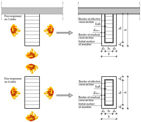
In the above expressions, t represents the duration of the fire. A simple graphic representation of the reduced cross-section method is shown in Figure 1, for the case when the fire acts on three and all four sides of the CS, the cases are analyzed here.
Figure 1.
Schematic representation of the reduced cross-section method.
The following expressions for the fire resistance proofs at the level of the CS area (element) were used in this study:
where and .
where and .
where and .
where and .
In the fire situation at time t, the cross–sectional mechanical resistance Rd,t,fi is obtained for the following points:
- -
- Fire coefficient kfi = 1.15;
- -
- The modification factor for fire, kmod,fi = 1.0, and
- -
- The partial safety factor for GLT in fire, γM,fi = 1.0 [8,9].
In Table 4, the calculated values of internal forces or actions, Ed,fi, using an accidental combination for actions [20], are presented.
Table 4.
Action effect design value, Ed, expressed in terms of internal forces from the fire (accidental) combination.
3. Results
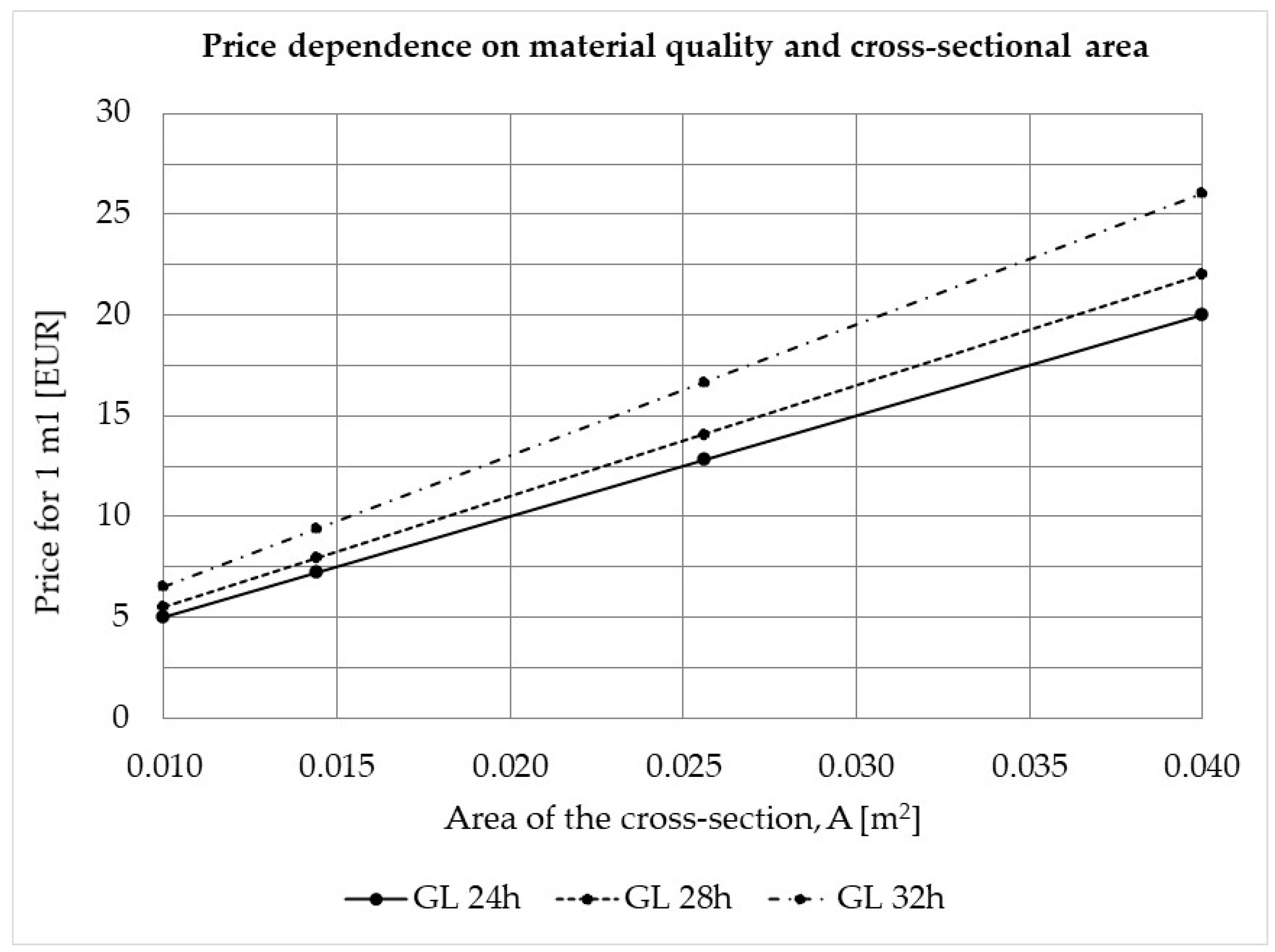
All obtained results, according to both methods, are presented in tabular form and graphically with some short comments. The price of the material is obtained according to the strength class of homogeneous GLT. It amounts to EUR 500.00/m3 for GL 24 h, EUR 550.00/m3 for GL 28 h and EUR 650.00/m3 for GL 32 h. The listed prices do not consider timber processing, protection with possible coatings, transport, and installation. The prices are expressed as fco construction site and are provided by company Stenavert in Croatia.
3.1. Results of the Limit States Method
The displayed values in Table 5 show the utilization of the analyzed cross-sections for a particular limit state, i.e., the state of stress depending on their area and the material’s strength class. The corresponding prices are expressed per meter length.
Table 5.
The utilization of cross-sectional area (element) of homogeneous glued laminated timber [1.0 = 100%].
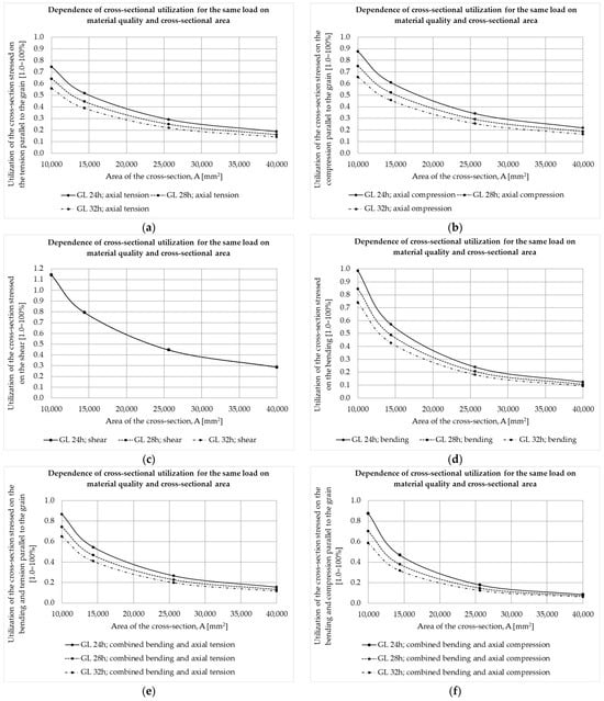
Figure 2 shows that all the load-carrying curves decline for a given limit stress state, depending on the changes in the cross-sectional area and the quality of the wooden material. At the same time, a decrease in the utilization of the CS for each individual type of action is evident. The effect of material quality on the load capacity of the CS, where higher quality mainly increases the load-bearing capacity of the CS, can be seen. It should be noted that only in the case of shear force or shear stress (Figure 2c), the quality of the material has no effect on the load capacity of the cross-section, due to the same characteristic shear strength fv,k for the selected strength classes of homogeneous GLT shown in Table 1 [1].
Figure 2.
Decreasing curves of elements’ CS utilizations: (a) tension parallel to the grain; (b) compression parallel to the grain; (c) shear; (d) bending; (e) bending tension parallel to the grain; (f) bending and compression parallel to the grain.
3.2. Results of the Reduced Cross-Section Method
For the given percentage of utilization of the CS obtained in the limit state method analysis for each particular stress-state case, the corresponding fire resistance values when the fire acts on three sides and on all four sides of the CS are shown in Table 6, Table 7, Table 8, Table 9, Table 10 and Table 11. The aforementioned utilization of the CS, when proving the load-bearing limit state, obviously has a great influence on the proof of fire resistance, regardless of which internal force type is acting on the CS (element). The price of the material obviously depends on the quality of the material (see Figure 3, as well as Table 6, Table 7, Table 8, Table 9, Table 10 and Table 11). Finally, Figure 4, Figure 5, Figure 6, Figure 7, Figure 8 and Figure 9 witness the increases in fire resistance with the increasing cross-sectional areas for various qualities of the material.
Figure 3.
Prices of materials depending on the strength class and cross-sections.
Figure 4.
Fire resistance of the elements’ cross-sections as a function of the cross-sectional area and strength class subjected to (a) tensile stress parallel to the grain when the fire acts on three sides of the cross-section; and (b) tensile stress parallel to the grain when fire acts on four sides of the cross-section.
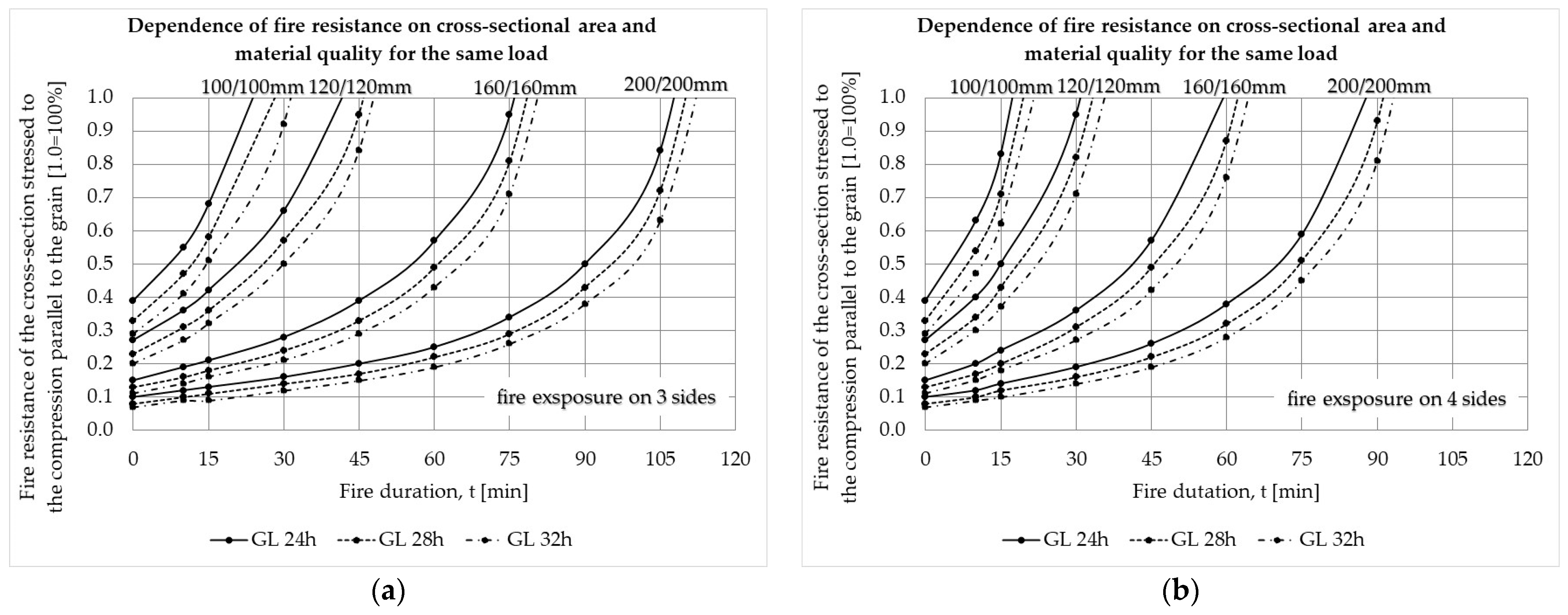
Figure 5.
Fire resistance of the elements’ cross-sections as a function of its cross-sectional area and strength class subjected to (a) compression parallel to the grain when the fire acts on three sides of the cross-section; and (b) compression parallel to the grain when fire acts on four sides of the cross-section.
Figure 6.
Fire resistance of the elements’ cross-sections as a function of its cross-sectional area and strength class subjected to (a) shear stress when the fire acts on three sides of the cross-section; and (b) shear stress when fire acts on four sides of the cross-section.
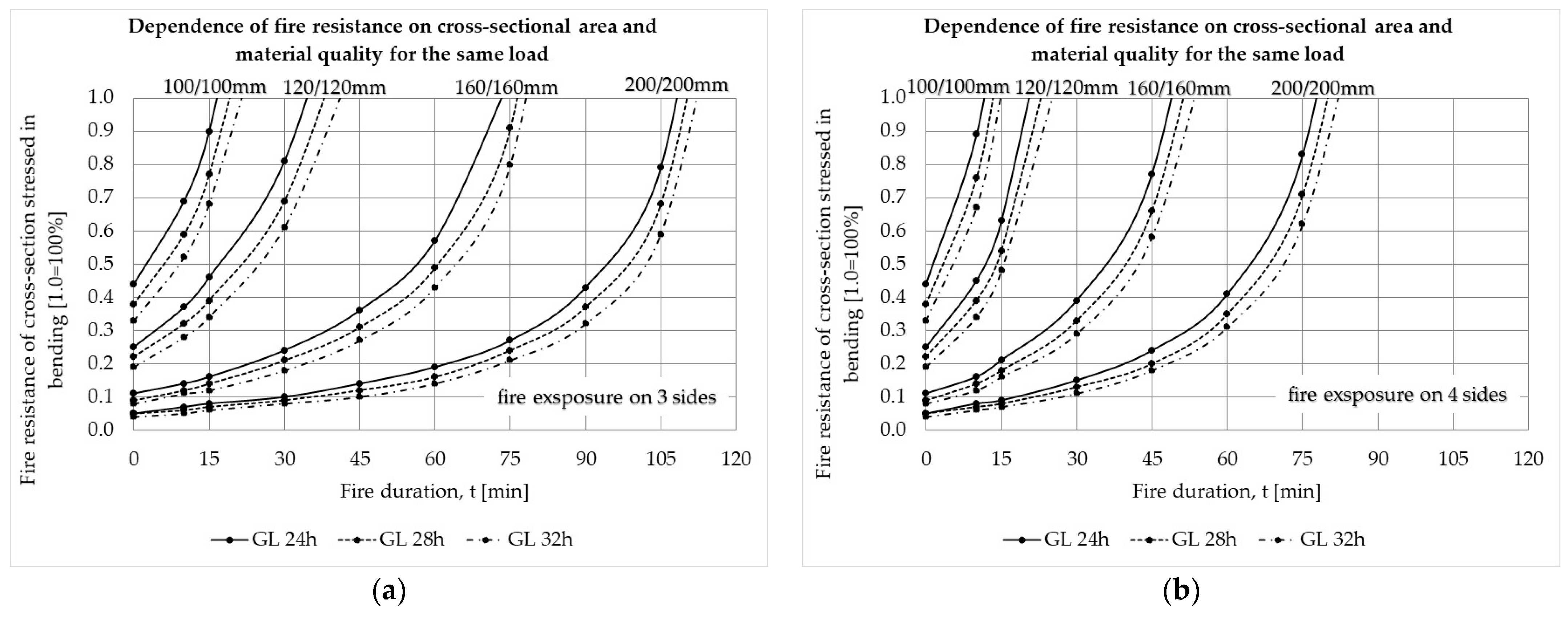
Figure 7.
Fire resistance of the elements’ cross-sections as a function of its cross-sectional area and strength class subjected to (a) bending when the fire acts on three sides of the cross-section; and (b) bending when fire acts on four sides of the cross-section.
Figure 8.
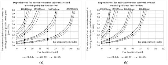
Fire resistance of the elements’ cross-sections as a function of its cross-sectional area and strength class subjected to bending and tension parallel to the grain (a) when the fire acts on three sides of the cross-section; and (b) when fire acts on four sides of the cross-section.
Figure 9.
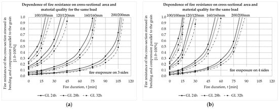
Fire resistance of the elements’ cross-sections as a function of its cross-sectional area and strength class subjected to bending and compression parallel to the grain (a) when the fire acts on three sides of the cross-section; and (b) when fire acts on four sides of the cross-section.
Table 6 shows the results of the fire resistance calculation expressed as a percentage of the cross-section’s utilization when the CS is exposed to tension parallel to the grain, depending on the duration of the fire in minutes. Also, the corresponding price shown depends on the element’s material quality and its cross-sectional area. For instance, the highlighted value (0.50) represents the percentage of the 100/100 mm CS utilization for the three-sided fire exposure of 15 min and the corresponding material price of EUR 5.50. All the gray shaded cells in tables represent the unacceptable fire resistance (values higher than 1.0) for a given cross-section, strength class and stress state. The same trends are applicable in all other tables, as seen in Table 6, Table 7, Table 8, Table 9, Table 10 and Table 11.
Table 6.
Fire resistance of the cross-sectional areas subjected to the tensile stress parallel to the grain [1.0 = 100%].
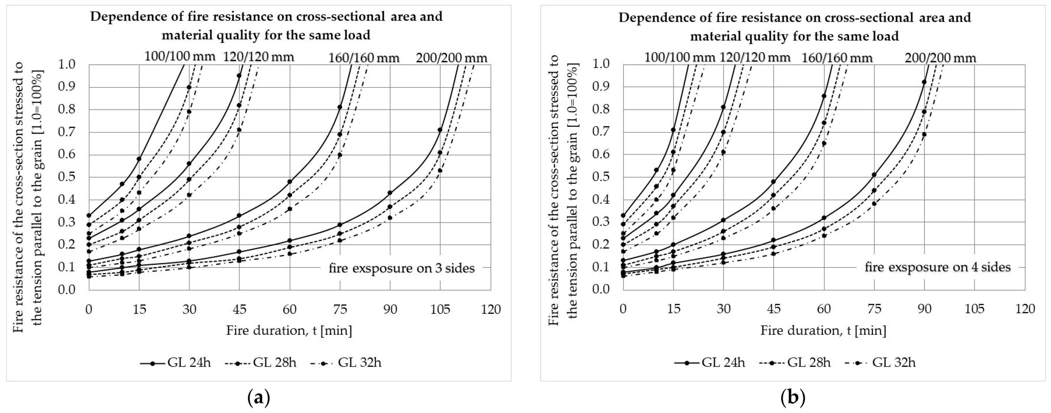
Fire resistance as a function of the fire duration, material quality, and cross-sectional area when the fire acts on three and all four sides of the CS loaded with a tensile force parallel to the grain is shown in Figure 4. The twice-larger CS can withstand an approximately 3.5 times longer fire duration (R105/R30, Figure 4a) regardless of the quality of the material when the fire acts on three sides, i.e., a six times longer fire duration (R90/R15, Figure 4b) when the fire acts on all four sides. At the same time, it should be kept in mind that a CS that is twice as large is approximately four times less utilized according to the load-bearing capacity; in other words, it is four times more expensive.
Table 7 shows the fire resistance calculation results when the CS is exposed to compression parallel to the grain, depending on the duration of the fire in minutes.
Table 7.
Fire resistances of the cross-sectional areas subjected to the compression parallel to the grain [1.0 = 100%].
Regarding the different characteristic mechanical properties of timber material and for various strength classes GLnh of GLT structural elements, the obtained results were as expected. Namely, there were obvious differences between tensile and compressive strengths at the very beginning of the analysis (Table 1). Given the fact that, in general, the compressive strength parallel to the grain of timber material is slightly higher than the corresponding tensile strength, the results obtained in terms of fire resistances are also slightly higher (Table 6 and Table 7). However, these relatively small differences in the achieved fire resistances do not necessarily increase the overall fire exposure in minutes.
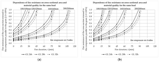
Fire resistance as a function of the fire duration, material quality, and cross-sectional area when the fire acts on three and all four sides of the CS loaded with compression force parallel to the grain is shown in Figure 5. The twice-larger CS can withstand an approximately seven times longer fire duration (R105/R15, Figure 5a) regardless of the quality of the material when the fire acts on three sides, which is a six times longer fire duration (R90/R15, Figure 5b) when the fire acts on all four sides. Again, as in the previous tension force case, a CS that is twice as large is approximately four times less utilized according to the load-bearing capacity, namely four times more expensive.
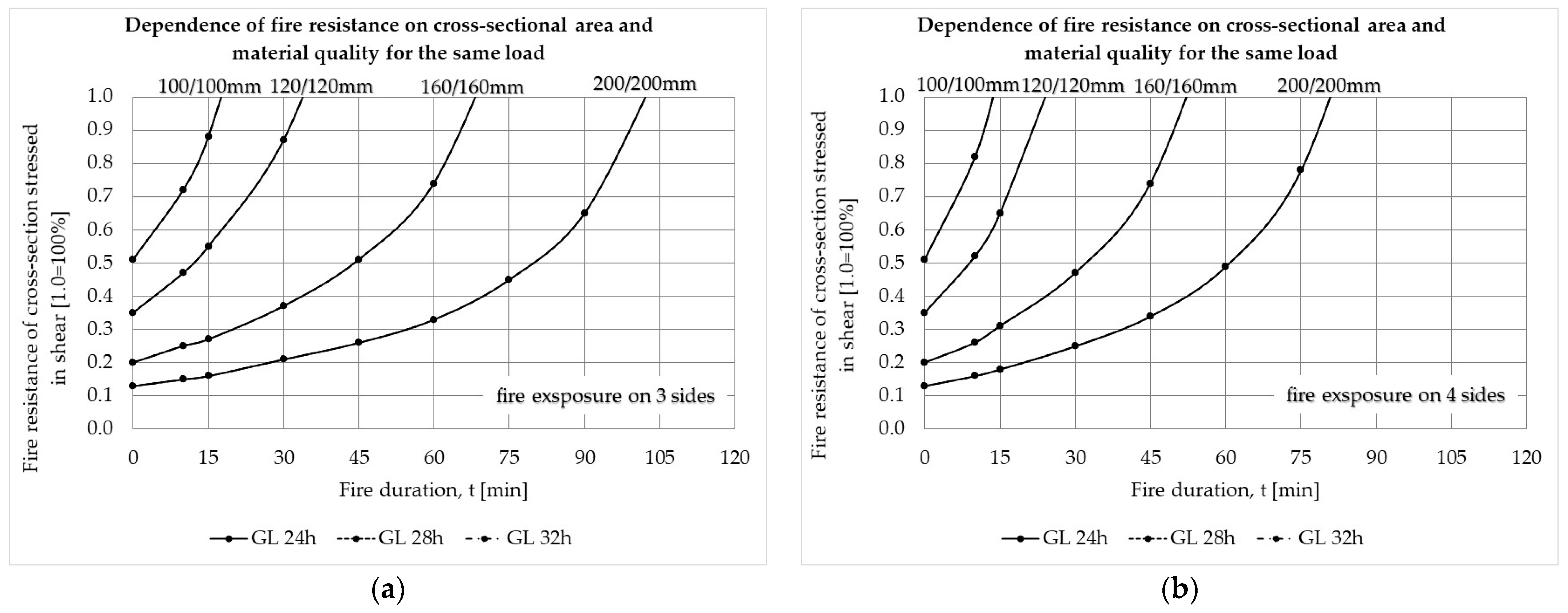
Table 8 shows the results of the fire resistance calculations when the CS is exposed to shear force, depending on the duration of the fire in minutes.
Table 8.
Fire resistances of the cross-sectional areas subjected to the shear stress [1.0 = 100%].
Fire resistance as a function of the fire duration, material quality, and cross-sectional area when the fire acts on three and all four sides of the CS loaded with shear force is shown in Figure 6. The twice-larger CS can withstand an approximately six times longer fire duration (R90/R15, Figure 6a) regardless of the quality of the material when the fire acts on three sides, or a five times longer fire duration (R75/R15, Figure 6b) when the fire acts on all four sides. In this case, however, a CS that is twice as large is approximately four times less utilized according to the load-bearing capacity. In other words, it is four times more expensive.
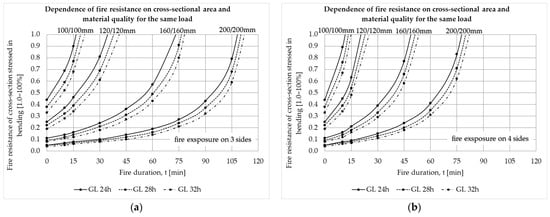
Table 9 shows the results of the fire resistance calculations when the CS is exposed to bending, depending on the duration of the fire in minutes.
Table 9.
Fire resistances of the cross-sectional areas subjected to bending [1.0 = 100%].
Fire resistance as a function of the fire duration, material quality, and cross-sectional area when the fire acts on three and all four sides of the CS loaded by bending is shown in Figure 7. The twice-larger CS can withstand an approximately 7-times longer fire duration (R105/R15, Figure 7a) regardless of the quality of the material when the fire acts on three sides, or 7.5-times longer fire duration (R75/R10, Figure 7b) when the fire acts on all four sides. At the same time, it should be kept in mind that a CS that is twice as large is approximately eight times less utilized according to the load-bearing limit state, but it is also four times more expensive.
Table 10 shows the results of the fire resistance calculations when the CS is exposed to combined bending and tension parallel to the grain, depending on the duration of the fire (in min).
Table 10.
Fire resistance of the cross-sectional areas subjected to combined bending and tension parallel to the grain [1.0 = 100%].
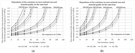
Fire resistance as a function of the fire duration, material quality, and cross-sectional area when the fire acts on three and all four sides of the CS loaded by bending and tension parallel to the grain are shown in Figure 8. The twice-larger CS can withstand an approximately seven times longer fire duration (R105/R15, Figure 8a) regardless of the quality of the material when the fire acts on three sides, and a five times longer fire duration (R75/R15, Figure 8b) when the fire acts on all four sides. For this load combination case, the CS that is twice as large is approximately 5.6 times less utilized according to the load-bearing limit state, but it is also four times more expensive.
Table 11 shows the results of the fire resistance calculations when the CS is exposed to combined bending and compression parallel to the grain, depending on the duration of the fire in min.
Table 11.
Fire resistance of the cross-sectional areas subjected to combined bending and compression parallel to the grain [1.0 = 100%].
Fire resistance as a function of the fire duration, material quality and cross-sectional area when the fire acts on three and all four sides of the CS loaded by bending and compression parallel to the grain is shown in Figure 9. The twice-larger CS can withstand an approximately seven times longer fire duration (R105/R15, Figure 9a) regardless of the quality of the material when the fire acts on three sides and a five times longer fire duration (R75/R15, Figure 9b) when the fire acts on all four sides. For this load combination case, the CS that is twice as large is approximately 10 times less utilized according to the load-bearing limit state, but it is also four times more expensive.
Overall, the increases in the fire resistance curves presented in Figure 4, Figure 5, Figure 6, Figure 7, Figure 8 and Figure 9 are evident in all of the analyzed stress states, showing high dependence on the changes in cross-sectional area and their exposure to fire but not much on the change in material quality. Only for shear stress (Figure 6a,b), the quality of the material has no effect whatsoever on the fire resistance of the cross-section.
3.3. Variation in Price on ULS and Fire Resistance
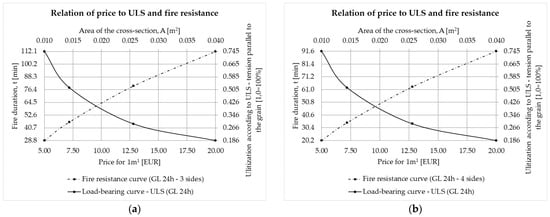
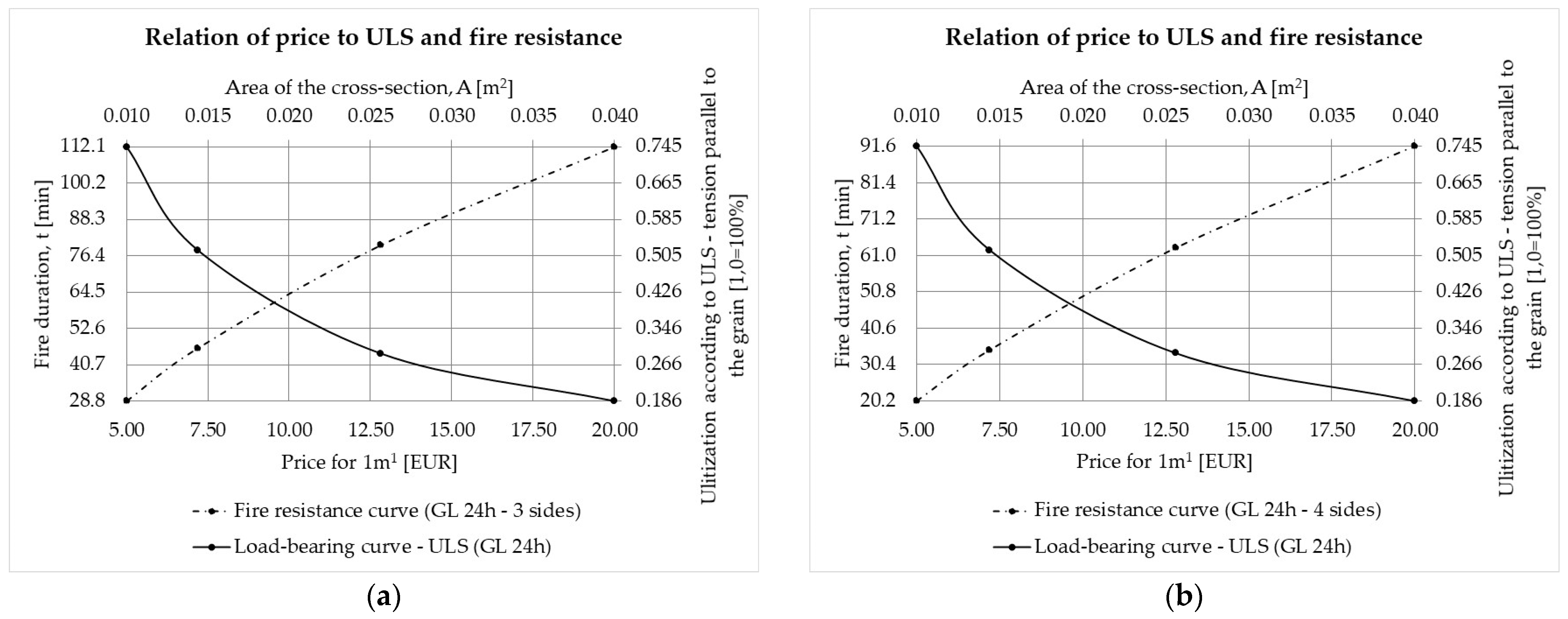
Descending bearing capacity utilizations and corresponding increasing fire resistance curves as functions of price variation for a given cross-sectional area and specifically for tension parallel to the grain stress case are presented on Figure 10. Namely, lower utilization of the CS capacity results in higher fire resistance but, at the same time, higher price. The optimal point for the fairest price is, in fact, the intersection point of both curves. The same applies for all other analyzed stress cases, i.e., strength classes of glued laminated timber. For example, from Figure 10a, it can be observed that if the CS is utilized at 74.5%, its fire resistance will be 28.80 min, for a price of EUR 5/m, and on the other hand, if the CS is utilized at 18.6%, its fire resistance will be 112.1 min, but at a price of EUR 20/m.
Figure 10.
Load-bearing capacity utilization and fire resistance curves (tension parallel to the grain) price variation for cross-section exposed to fire on (a) three sides and (b) four sides.
The practical application of this research is reflected in the fact that now, based on the utilization of the CS (element) when proving the load-bearing limit state, the designer can determine in the early stage of design process the expected fire resistance of the CS according to the duration of the fire on three or all four sides and depending on the stress case and the quality of the material with a simultaneous insight into the price of the material.
4. Conclusions
In today’s practice, thanks to more elaborate regulations, fire resistance calculations and analyses attract a growing interest in both engineering and research communities. After extensive research and the processing and interpretation of numerical results for each of the described methods applied on selected sets of cross-sections (CS) and strength classes of glued laminated timber (GLT), the following conclusions can be drawn.
- The fire resistance of timber structures made of GLT calculated with the reduced cross-section method tends to be directly affected by the load bearing capacity proving procedure, which is not the case with structures made of other structural materials like concrete or steel.
- Utilization of the element’s cross-section has a particular impact on its fire resistance. Namely, if the element’s CS is utilized at 87.50% for any load action or their combination and for any GLT strength class, it does not meet a fire resistance higher than R15 in case that the fire acts on its three sides. Increasing the cross-sectional area has, as a result, decreased the utilization of the element’s CS. At the same time, fire resistance increases as well as the price of the material.
- Fire resistance obviously depends on the cross-section’s exposure to fire. For example, if one specific CS satisfies the fire resistance class of R30 and the fire acts on its three sides, the same CS will not meet the stated fire resistance if the fire acts on its all four sides.
- The increase in the GLT strength class for any action or stress state does not contribute significantly to fire resistance. The contribution of the increase in the strength class is manifested only in the improved utilization of the cross-section’s bearing capacity for the same fire exposure class. The only exception is in the case of shear, where the increase in the GLT strength class has no effect on fire resistance at all.
- To achieve a certain fire resistance according to the load-bearing criterion R, the price of the timber material might also have a deciding impact. By variating the specific fire resistance class for a given stress state of the CS, the corresponding timber material price might increase by up to four times.
- By correlating the load limit state capacity proof and the corresponding fire resistance functions, it is quite easy for any stress state case to obtain the optimal price for timber material as their intersection point. For example, if the CS is subjected to tension parallel to the grain and the fire acts on its three or four sides, the optimal price can be obtained if that section is utilized approximately to 40% of the bearing capacity. It is expected, in that case, that CS will withstand the fire action duration on the section’s three sides of approximately 60 minutes and 45 minutes if the fire acts on the section’s all four sides.
The results of the parametric analysis presented in this study clearly indicate the importance of the bearing capacity proofing procedure in the determination of the GLT fire resistance. We are convinced that these results, especially the fire resistance tables, might help in the early design phase, where the proper/optimal selection of the elements’ cross-sections can greatly affect its required fire resistance. It has to be mentioned that all the obtained results are numerically derived on square cross-sections and simple geometry of timber girders. But we are aware that some of the stress states, such tension or compression perpendicular to the grain, are not covered in this research, although they might be essential in the overall design procedure of GLT girders, such as, for instance, single- and double-tapered beams, curved beams of constant depth, pitched cambered, or fish-bellied beams.
The next step in this research should involve the interaction assessment of the element stability check procedure, i.e., element buckling, lateral buckling, or their combination, on its fire resistance. Moreover, what might follow is also the determination of the impact of passive fire protection measures on the total price of such a protected element for a certain fire duration.
Author Contributions
Conceptualization, J.Z. and Z.D.-A.; methodology, J.Z.; software, J.Z.; formal analysis, J.Z. and I.G.; investigation, J.Z. and Z.D.-A.; data curation, J.Z.; writing—original draft preparation, J.Z. and I.G.; writing—review and editing, J.Z., Z.D.-A. and I.G.; visualization, J.Z. All authors have read and agreed to the published version of the manuscript.
Funding
This research received no external funding.
Institutional Review Board Statement
Not applicable.
Informed Consent Statement
Not applicable.
Data Availability Statement
The original contributions presented in the study are included in the article, further inquiries can be directed to the corresponding author.
Conflicts of Interest
The authors declare no conflicts of interest.
Abbreviations
The following abbreviations are used in this manuscript:
| GLT | Glued laminated timber |
| CS | Cross-section |
| ULS | Ultimate limit state |
References
- EN 14080:2013; Timber Structures—Glued Aminated Timber and Glued Solid Timber—Requirements. European Committee for Standardization (CEN): Brussels, Belgium, 2013.
- Jirouš-Rajković, V.; Miklečić, J. Fire retardants for wood. Drv. Ind. 2009, 60, 111–121. [Google Scholar]
- EN 1995-1-2:2004+AC:2009; Eurocode 5: Design of Timber Structures—Part 1-2: General-Structural Fire Design. European Committee for Standardization (CEN): Brussels, Belgium, 2009.
- Klippel, M.; Frangi, A. Fire safety of glued-laminated timber beams in bending. J. Struct. Eng. 2017, 143, 04017052. [Google Scholar] [CrossRef]
- Wang, Y.; Zhang, J.; Mei, F.; Liao, J.; Li, W. Experimental and numerical analysis on fire behavior of loaded cross-laminated timber panels. Adv. Struct. Eng. 2020, 23, 22–36. [Google Scholar]
- Pečenko, R.; Svensson, S.; Hozjan, T. Modelling heat and moisture transfer in timber exposed to fire. Int. J. Heat Mass Transf. 2015, 87, 598–605. [Google Scholar] [CrossRef]
- Yang, T.; Wang, S.; Tsai, M.; Lin, C. Temperature distribution within glued laminated timber during a standard fire exposure test. Mater. Des. 2009, 30, 518–525. [Google Scholar] [CrossRef]
- Yang, T.; Wang, S.; Tsai, M.; Lin, C. The charring depth and charring rate of glued laminated timber after a standard fire exposure test. Mater. Des. 2009, 44, 518–525. [Google Scholar] [CrossRef]
- Firmanti, A.; Subiyanto, B.; Kawai, S. Evaluation of the fire endurance of mechanically graded timber in bending. J. Wood Sci. 2006, 52, 25–32. [Google Scholar]
- Frangi, A.; Fontana, M.; Mischler, A. Shear behavior of bond lines in glued laminated timber beans at high temperature. Wood Sci. Technol. 2004, 38, 119–126. [Google Scholar] [CrossRef]
- Yang, T.; Wang, S.; Tsai, M.; Lin, C.; Chuang, Y. Effect of fire exposure on the mechanical properties of glued laminated timber. Mater. Des. 2009, 30, 698–703. [Google Scholar] [CrossRef]
- Huang, J.; Wang, L. Experimental and numerical study on progressive collapse of the midcolumn in a glulam timber frame exposed to fire. Fire 2023, 6, 374. [Google Scholar] [CrossRef]
- Schmid, J.; Klippel, M.; Just, A.; Frangi, A. Review and analysis of fire resistance tests of timber members in bending, tension and compression with respect to the Reduced Cross-Section Method. Fire Saf. J. 2014, 68, 81–99. [Google Scholar] [CrossRef]
- Kucíková, L.; Janda, T.; Sýkora, J.; Šejnoha, M.; Marseglia, G. Experimental and numerical investigation of the response of GLT beams exposed to fire. Constr. Build. Mater. 2021, 299, 123846. [Google Scholar] [CrossRef]
- Tang, Z.; Yue, K.; Lu, D.; Shi, X.; Chu, Y.; Tian, Z.; Lu, W. Experimental investigation into fire performance of mixed species glulam beams under three-side fire exposure. Eur. J. Wood Wood Prod. 2022, 80, 235–245. [Google Scholar] [CrossRef]
- Ulusoy, S. Optimum design of timber structures under fire using metaheuristic algorithm. Građevinar 2022, 74, 115–124. [Google Scholar] [CrossRef]
- EN 1995-1-1; Eurocode 5: Design of Timber Structures-Part 1-1: General-Common Rules and Rules for Buildings. European Committee for Standardization (CEN): Brussels, Belgium, 2013.
- EN 1995-1-1:2004/A2:2014; Eurocode 5: Design of Timber Structures-Part 1-1: General-Common Rules and Rules for Buildings. European Committee for Standardization (CEN): Brussels, Belgium, 2014.
- HRN EN 1995-1-1:2013/NA:2013; Eurokod 5: Projektiranje Drvenih Konstrukcija–Dio 1-1: Općenito-Opća Pravila i Pravila za Zgrade-Nacionalni Dodatak Eurocode 5: Design of Timber Structures-Part 1-1: General-Common Rules and Rules for Buildings-National Annex. Hrvatski Zavod za Norme: Zagreb, Hrvatska, 2013.
- CEN. EN 1990 Eurocode-Basis of Structural and Geotechnical Design; European Committee for Standardization (CEN): Brussels, Belgium, 2023. [Google Scholar]
- HRN EN 1995-1-2:2013/NA:2013; Eurokod 5: Projektiranje Drvenih Konstrukcija-Dio 1-2: Općenito-Proračun Konstrukcija na Djelovanje Požara-Nacionalni Dodatak Eurocode 5: Design of Timber Structures-Part 1-2: General-Structural Fire Design-National Annex. Hrvatski Zavod za Norme: Zagreb, Hrvatska, 2013.
- EN 1363-1; Fire Resistance Tests—Part 1: General Requirements. European Committee for Standardization (CEN): Brussels, Belgium, 2020.


Disclaimer/Publisher’s Note: The statements, opinions and data contained in all publications are solely those of the individual author(s) and contributor(s) and not of MDPI and/or the editor(s). MDPI and/or the editor(s) disclaim responsibility for any injury to people or property resulting from any ideas, methods, instructions or products referred to in the content. |
© 2025 by the authors. Licensee MDPI, Basel, Switzerland. This article is an open access article distributed under the terms and conditions of the Creative Commons Attribution (CC BY) license (https://creativecommons.org/licenses/by/4.0/).