Article

Numerical Study of Fire-Induced Steel Frame Collapse: Validation of Experiments Using Static and Dynamic Methods

FireSERT, Ulster University, Jordanstown Campus, Belfast BT370QB, UK
*
Authors to whom correspondence should be addressed.
Fire 2025, 8(11), 420; https://doi.org/10.3390/fire8110420
Submission received: 31 August 2025 / Revised: 22 October 2025 / Accepted: 24 October 2025 / Published: 29 October 2025

Abstract

This paper presents a validated computational workflow for simulating the fire-induced collapse of steel moment-resisting frames, comparing static general and dynamic explicit analysis procedures. Whereas most existing studies employ dynamic explicit analysis for collapse validation, this work evaluates the capability of the static general approach as a viable alternative. Finite element models developed with beam and shell elements capture both global instability and local failure modes. The results show that the static general procedure effectively reproduces quasi-static post-buckling behaviour and predicts the critical failure temperature within 2–3% of experimental results, similar to the dynamic explicit method. For the dynamic explicit procedure, sensitivity analyses are conducted to optimise time scaling, mesh refining, and ensure realistic physical response while maintaining computational efficiency. The study demonstrates that, along with dynamic explicit analysis, static general procedure also offers a practical and reliable alternative for simulating fire-induced structural collapse, reducing computational time by up to eighteen times for beam models and around six times for shell models, while maintaining reliable accuracy.

1. Introduction

Progressive collapse happens when a small part of a structure is damaged, and initial damage triggers a chain reaction that causes the entire structure, or a large part of it, to collapse. Essentially, a minor local failure grows and affects other parts of the structure, leading to a much bigger collapse [1]. The catastrophic collapse of buildings in the World Trade Centre (WTC) complex in 2001 due to initially localised failure followed by fire highlighted the importance of understanding building performance under fire. Since testing entire frames under multiple fire scenarios is impractical, computational modelling is essential for studying potential failure mechanisms and developing rational design methods. The simulation of structures exposed to fire is critical in structural fire engineering for assessing integrity and predicting failure modes. Finite element software like Abaqus is commonly employed due to its Multiphysics capabilities, including thermo-structural analysis. Typically, fire-induced collapse behaviour is simulated using line (beam) elements with the dynamic explicit solver, as this provides a convenient way to model large deformation behaviour while avoiding convergence problems and keeping the computational cost manageable. However, dynamic explicit analysis generally requires longer computational time than static analysis. This limitation becomes more restrictive when attempting to model collapse behaviour using only line elements. Furthermore, while line-element models efficiently capture global structural response, they cannot represent local failure modes such as web or flange buckling, connection failures, or local heat-induced distortions. To address this, shell elements are often employed, which can capture local instabilities. Nevertheless, shell-element models significantly increase computational time because each shell element has four nodes (compared with two nodes for a beam element), resulting in a larger number of degrees of freedom and a smaller critical time step size in explicit analysis. Consequently, explicit simulations using shell elements become even more computationally demanding, especially for full-frame structural models under fire exposure.
A number of researchers have investigated the fire-induced progressive collapse of steel structures using simplified modelling approaches based primarily on beam elements within commercial finite element (FE) packages. Agarwal and Varma [2] pioneered one of the earliest studies in this area, demonstrating a framework for simulating the post-fire collapse of steel moment-resisting frames. Their approach relied on beam (line) elements in Abaqus to capture the global deformation and catenary action under fire, while incorporating temperature-dependent material degradation in the constitutive model. Their subsequent study [3] examined the role of interior gravity columns on collapse resistance, with emphasis on connection temperature–time histories, thereby highlighting the impact of redundant load paths on structural robustness. Shakeri et al. [4] analysed the intermediate moment-resisting steel frames subjected to fire-induced column loss using a line-element model in Abaqus, applying an explicit dynamic approach to study the subsequent progressive collapse mechanisms. Their research highlighted the importance of column axial restraints and rotational stiffness in collapse resistance. In thin-walled steel structures, Roy et al. [5] used the finite element programme Abaqus to examine the collapse of a cold-formed steel building under fire. Again, using beam elements, the study showed that stiffness and bracing layout significantly influence the failure temperature and sequence. Jiang et al. [6] employed an explicit dynamic beam element model in Abaqus to investigate disproportionate collapse of gravity steel frames under travelling fires. Their results underlined the sensitivity of progressive collapse behaviour to the heating rate and location of the travelling fire front. Rackauskaite et al. [7,8], similarly, utilised beam element models in Abaqus to compare collapse initiation mechanisms under traditional ‘uniform’ design fires and travelling fires in multi-storey frames. Importantly, these studies confirmed that beam element models are capable of capturing global instability and catenary action but cannot model localised buckling or connection failure.
For model validation, most of the aforementioned numerical studies rely on classic experimental benchmarks such as the tests on steel portal frames by Rubert and Schaumann [9] and the restrained steel column fire tests conducted by Li et al. [10]. Suwondo et al. [11] have attempted to simulate the complete fire-induced progressive collapse of a planar moment-resisting frame using a beam-element model in Abaqus and by validating against the furnace tests reported by Jiang et al. [12]. However, their modelling framework employed a model created with a beam element and a single uniform temperature profile along the length of the heated columns and beams for the sake of simplicity. This represents a key limitation, as the original experiment by Jiang et al. [13] demonstrated significant temperature gradients both along and across the structural members, which strongly influenced failure mode and collapse sequencing. Trial analyses performed in the present study confirm that the use of a simplified temperature distribution can lead to substantial discrepancies in the predicted structural response. This observation is consistent with the findings reported by Jiang et al. [13], who showed that non-uniform temperature profiles along beam elements considerably affect deflections, stiffness degradation, and overall collapse behaviour. Hence, there remains a clear need for a comprehensive and realistic modelling approach that accounts for member-level temperature variations, particularly when simulating progressive collapse of steel moment frames under travelling or localised fires.
Collectively, these studies indicate that progressive collapse under fire is predominantly simulated using beam-element models under dynamic-explicit solvers to avoid convergence difficulties during large deformations. However, a major limitation of these line-element models is their inability to represent local failure modes (e.g., flange/web buckling, joint failure, lateral-torsional buckling), which are critical in fire. To capture such local instabilities, highly capable shell-element models are required, although their use is computationally intensive, particularly within dynamic-explicit analysis, which imposes small stable time steps. As a result, the purpose of this study is to systematically evaluate the capability of static general and dynamic explicit analysis procedures in predicting fire-induced collapse of steel frames. Specifically, the study aims to assess their comparative accuracy, numerical stability, and computational efficiency when applied to both beam and shell element models.

2. Materials and Methods

2.1. Validation Framework

This research particularly investigates the application of the static general solution in capturing the progressive collapse of steel frames under fire. For validation, the benchmark experimental study conducted by Jiang et al. [12], on planar moment-resisting steel frames exposed to fire, was considered. The experimental programme of Jiang et al. [12] included three frame tests. Amongst the three tests, Frame 2 was selected for validation because the frame demonstrates both sudden buckling and the development of catenary action without being an extreme case, making it the most representative and reliable test for numerical model comparison. In addition, further validation was carried out using the experimental programme on two bay planar steel frame reported by Rubert and Suchman [9] to ensure the robustness of the modelling procedure discussed in the following sections.

2.2. Numerical Modelling

The numerical model was developed using both beam and shell elements. Specifically, the B31 element was employed for beam modelling, while the S4R element was adopted for shell modelling, both available in the Abaqus element library [14]. The B31 element is a one-dimensional line element with two nodes that represents the geometry through its length, while cross-sectional properties are defined separately. Each node carries six degrees of freedom, allowing the element to capture axial forces, bending about two axes, shear, and torsion. In contrast, the S4R element is a 4-node quadrilateral shell element with reduced integration, used for modelling plates, slabs, walls, and curved shell structures [15]. It is a two-dimensional surface element with an assigned thickness and also has six degrees of freedom per node. Unlike beam elements, shell elements can capture both in-plane membrane actions and out-of-plane bending as well as local phenomena like plate buckling.
The cross-sectional properties of each member were defined according to the experimental specimen geometry. The steel material properties were modelled as temperature-dependent, following the reduction factors for elastic modulus and yield strength prescribed in Eurocode 3 (EN 1993-1-2) [16]. The true stress–strain relationship was implemented in the model to capture the real plastic behaviour of the material under large deformation. Although Eurocode [16] provides an idealised elastic–perfectly plastic model for fire design, this simplification may underestimate strain hardening effects and post-yield behaviour. Therefore, the engineering stress–strain data were converted to true stress–strain form to better represent the material response at elevated temperatures. The analysis was performed in two sequential steps [17]. In the first step, static gravitational loads equivalent to the experimental configuration were applied to the structure. In the second step, thermal loading was introduced by directly applying the time histories from the fire test to the relevant elements in the model, ensuring a close correlation between the simulated thermal field and the physical test conditions. The beam-to-column connection was considered using the tie constraint option in Abaqus. All the column bases were modelled as fixed supports, restraining all six degrees of freedom (three translational and three rotational).

3. Results and Discussion

3.1. Case Study 1

3.1.1. Test Details of Case Study 1

This validation is based on the second of three large-scale steel moment frame fire tests conducted at Tongji University, China, to investigate progressive collapse resistance under localised heating [12]. The test frame was a two-storey, four-bay planar steel moment frame, with middle bay spans of 2.2 m, side bay spans of 2.0 m, and storey heights of 1.3 m and 1.2 m for the first and second floors, respectively. The columns consisted of rectangular hollow steel tubes with dimensions of 50 × 30 × 3 mm. The beams were rectangular hollow sections measuring 60 × 40 × 3.5 mm. Both the beams and columns were fabricated from carbon structural steel with an elastic modulus of 208 GPa. The yield strength of the steel column and beam was 361 MPa and 290 MPa for the columns and beams, respectively.
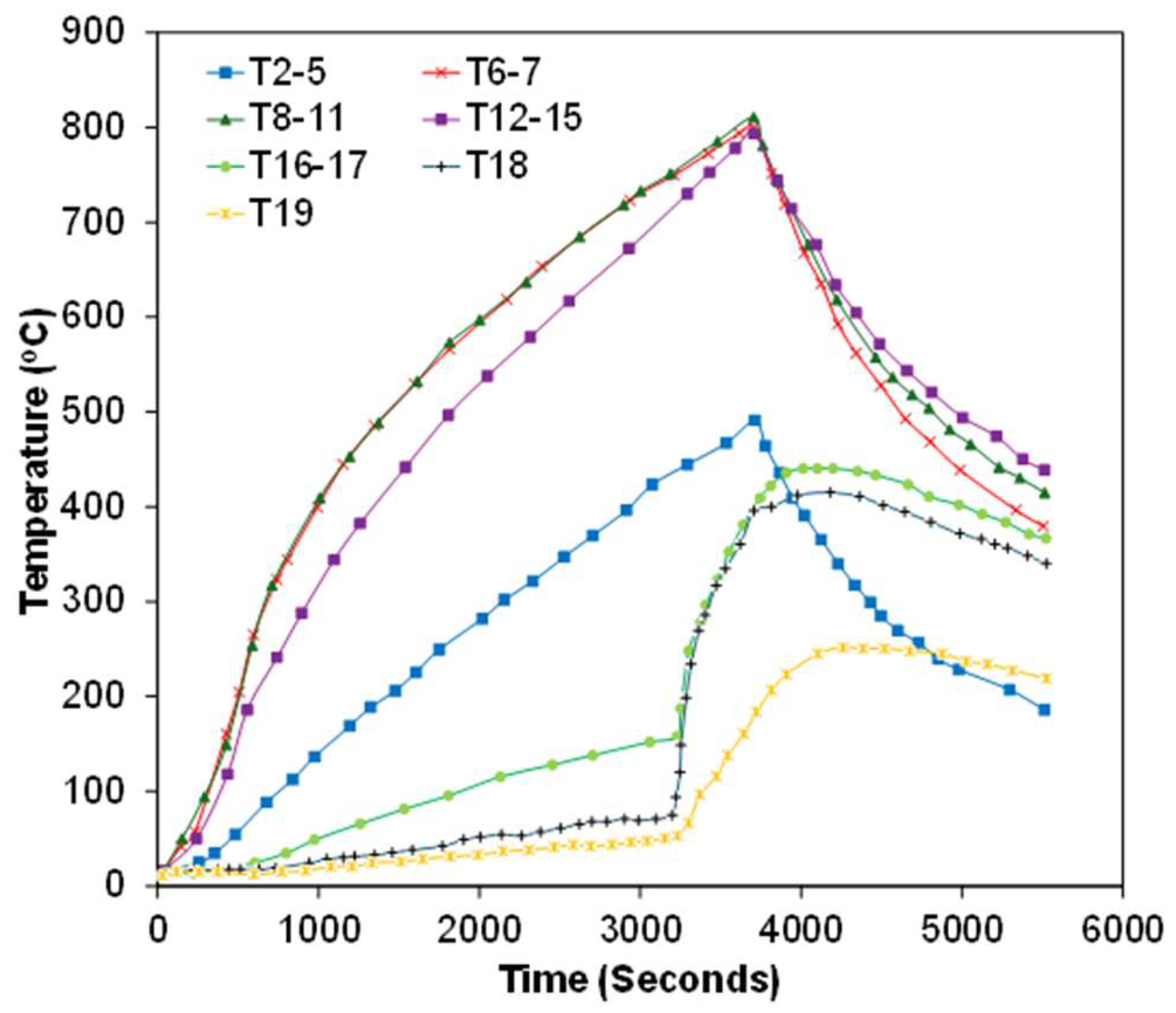
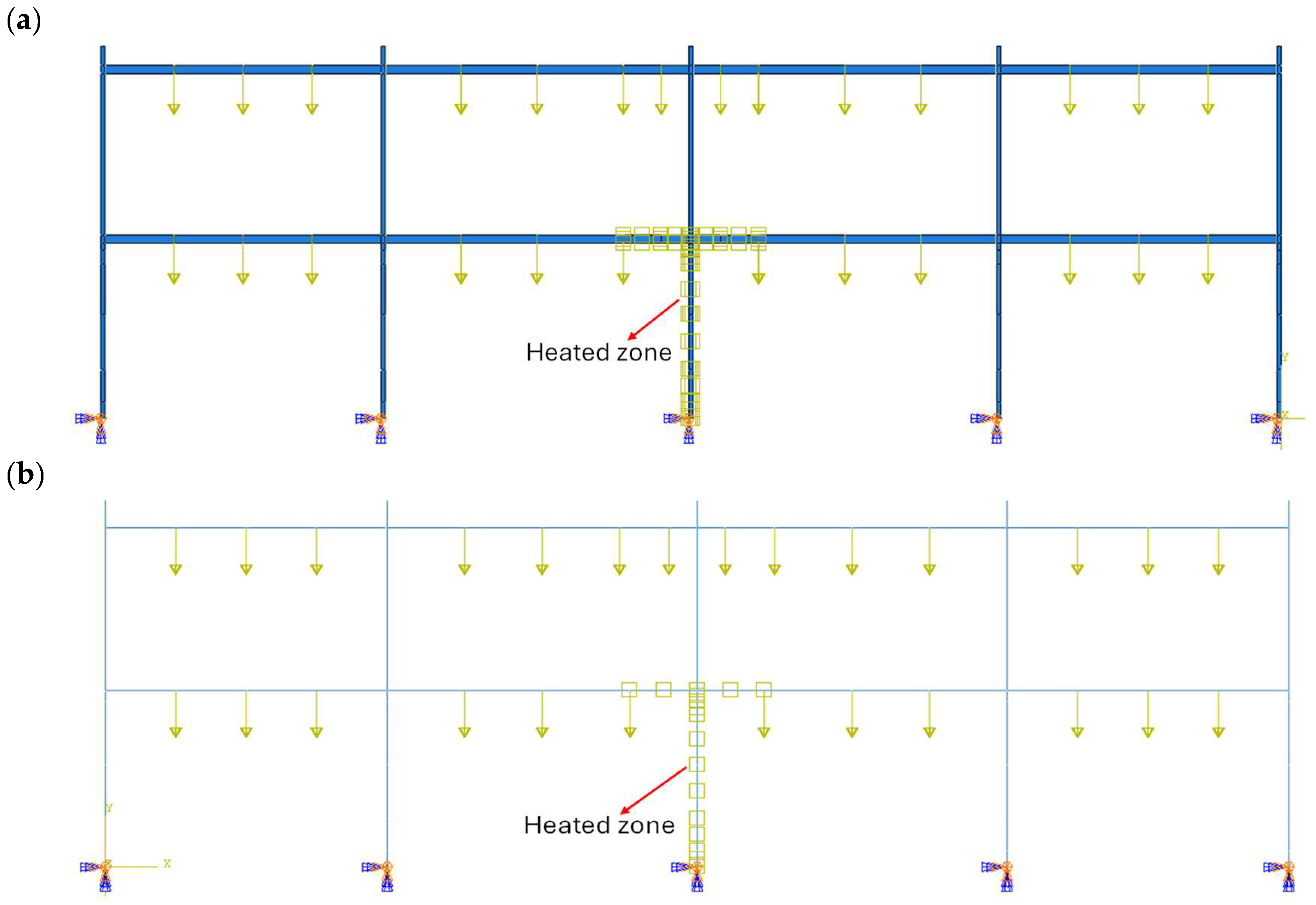
Gravity loads were applied using steel boxes filled with metal lumps, giving a column axial load of 14.0 kN at ambient temperatures, with an axial restraint stiffness of 2.881 × 10² kN/m. The central first-storey column was heated using a custom vertical electric furnace. The furnace was switched off when the maximum gas temperature reached 829 °C at 3660 s (61 min), after which cooling-phase behaviour was monitored for ~25 min. The heated column buckled suddenly at ~3169 s (53 min), producing a rapid vertical drop of the column top to an equilibrium displacement of 55 mm. This sudden buckling led to hot gas escape and the secondary heating of adjacent beams, and tensile forces developed in beams above the failed column, indicating catenary action. This test captured the dynamic effects caused by sudden column buckling under localised fire conditions. It also shows that the test is suitable as a benchmark for progressive collapse modelling in fire scenarios. The schematic diagram in Figure 1 shows frame geometry and loading data, while Figure 2 shows the temperature profile of the heated section of the frame recorded during experimental testing. Figure 3a,b shows the shell element and line element model created in Abaqus software.
The first set of simulations was performed using the dynamic explicit solver. In explicit analysis, the choice of total simulation time is critical to achieving a balance between computational efficiency and accuracy. Typically, dynamic explicit analysis requires longer runtimes compared to static analysis because the stable time increment is automatically calculated based on the smallest element size and material properties, following the Courant stability criterion (Δt ≤ Le/c), where Le is the characteristic element length and c is the wave speed. While shorter simulation times can reduce computational cost through time scaling, they may also introduce artificial dynamic effects that are not representative of the quasi-static response. Conversely, excessively long simulation times increase computational effort without significant improvements in accuracy. In this study, different total analysis times of 5 s, 10 s, and 15 s were investigated. Moreover, both meshing and simulation time directly influence the overall computational cost and accuracy of the analysis. To systematically evaluate these effects, a sensitivity analysis was performed considering variations in both factors. Specifically, three different simulation times (5 s, 10 s, and 15 s) and four different mesh sizes (100 mm, 75 mm, 50 mm, and 25 mm) were investigated. The objective was to identify the combination of simulation time and mesh refinement that produces results closest to experimental observations, while also maintaining a balance between computational efficiency and accuracy. For the static general analysis, the overall procedure remained the same as described above, with the addition of initial geometric imperfections to trigger collapse. These imperfections were introduced through a preliminary buckling analysis, and the imperfections were imposed based on a selected buckling mode shape. A detailed procedure for incorporating imperfections is presented in our previous study [18]. For the static analysis, the actual time history obtained from the experimental fire test was applied as the temperature.

3.1.2. Analysis Using Dynamic Explicit Step

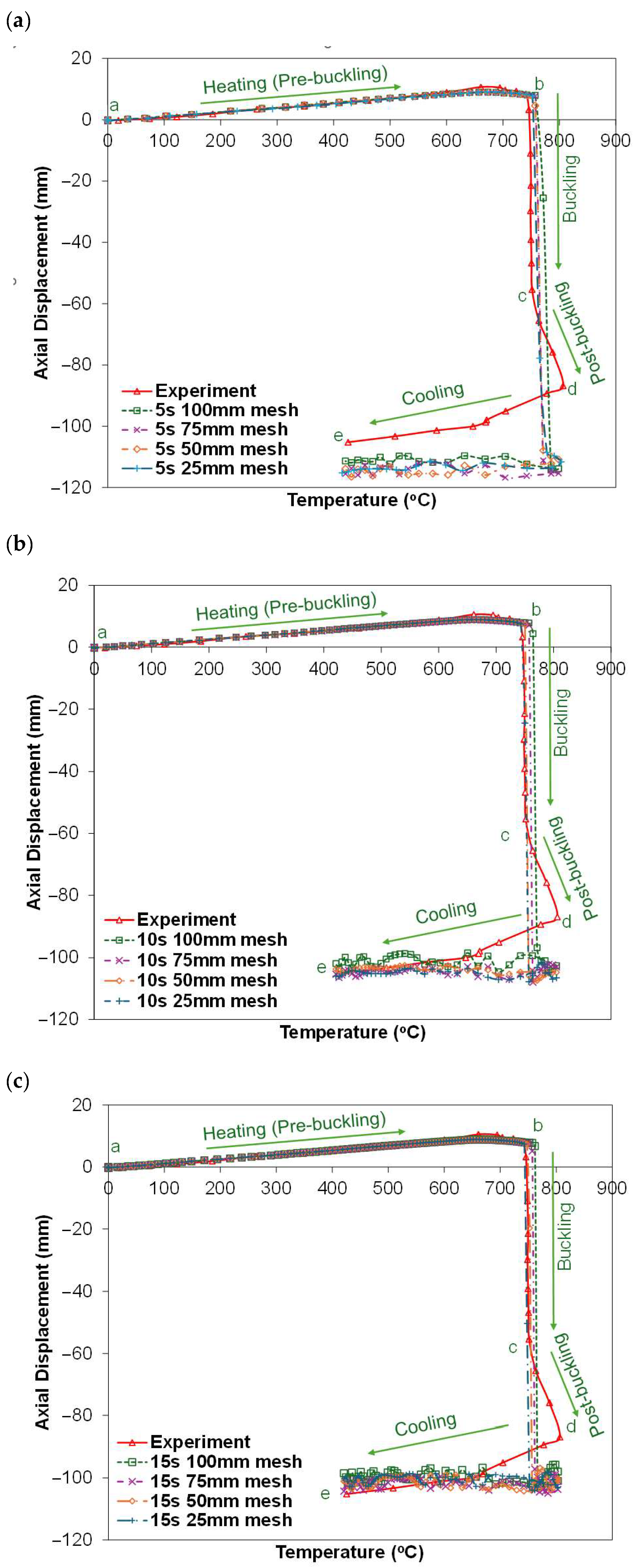
Figure 4a–c shows analysis results with the dynamic explicit method in Abaqus using beam elements. The simulations were carried out with three different time scales (5 s, 10 s, and 15 s) and four mesh sizes (100 mm, 75 mm, 50 mm, and 25 mm). The behaviour of an axially restrained column at elevated temperatures can be described in four distinct stages [19], as illustrated in Figure 4a–c. In stage a–b (pre-buckling), the column remains stable while the axial displacement increases due to thermal expansion during heating. stage b–c represents the buckling phase, where the compressive load reaches the critical resistance, leading to sudden lateral deflection and a sharp drop in load. Stage c–d corresponds to the post-buckling phase, during which the column continues to deform laterally until a new equilibrium is reached. Finally, stage d–e represents the cooling phase, where thermal contraction dominates. Depending on the extent of damage, the column may partially recover its strength or undergo additional instability during this stage.
To examine how well these stages are reproduced in the numerical model, simulations were performed under different heating durations. When the heating was applied in 5 s, the results from all mesh sizes show a similar behaviour to the experiment. The critical temperature, where the frame loses strength and collapses, is almost the same as the test result (within about 2% difference). However, after reaching this critical temperature, the simulation shows a larger downward displacement compared to the experiment. This could be attributed to the short time scale, which makes the loading very fast, and the explicit method introduces dynamic effects. With the 10 s time scale, the results are smoother and more stable. The axial shortening is smaller compared to the 5 s case, and the scatter between different mesh sizes is reduced. This happens because applying the heating more slowly reduces the dynamic effects. The simulation becomes closer to quasi-static conditions, which means the response is mainly controlled by the stiffness and strength of the structure, not by the artificial inertia from the loading rate. At the 15 s time scale, the results are the closest match to the experiment. This shows that when the heating is applied over a longer time, the analysis captures the behaviour more accurately, with very little influence from dynamic effects. Furthermore, the analysis time in dynamic explicit analysis is highly sensitive to the selected time scale and mesh size. For the current test validation, the analysis time increases, ranging from approximately 25% to 60% at a higher time scale and finer mesh size.
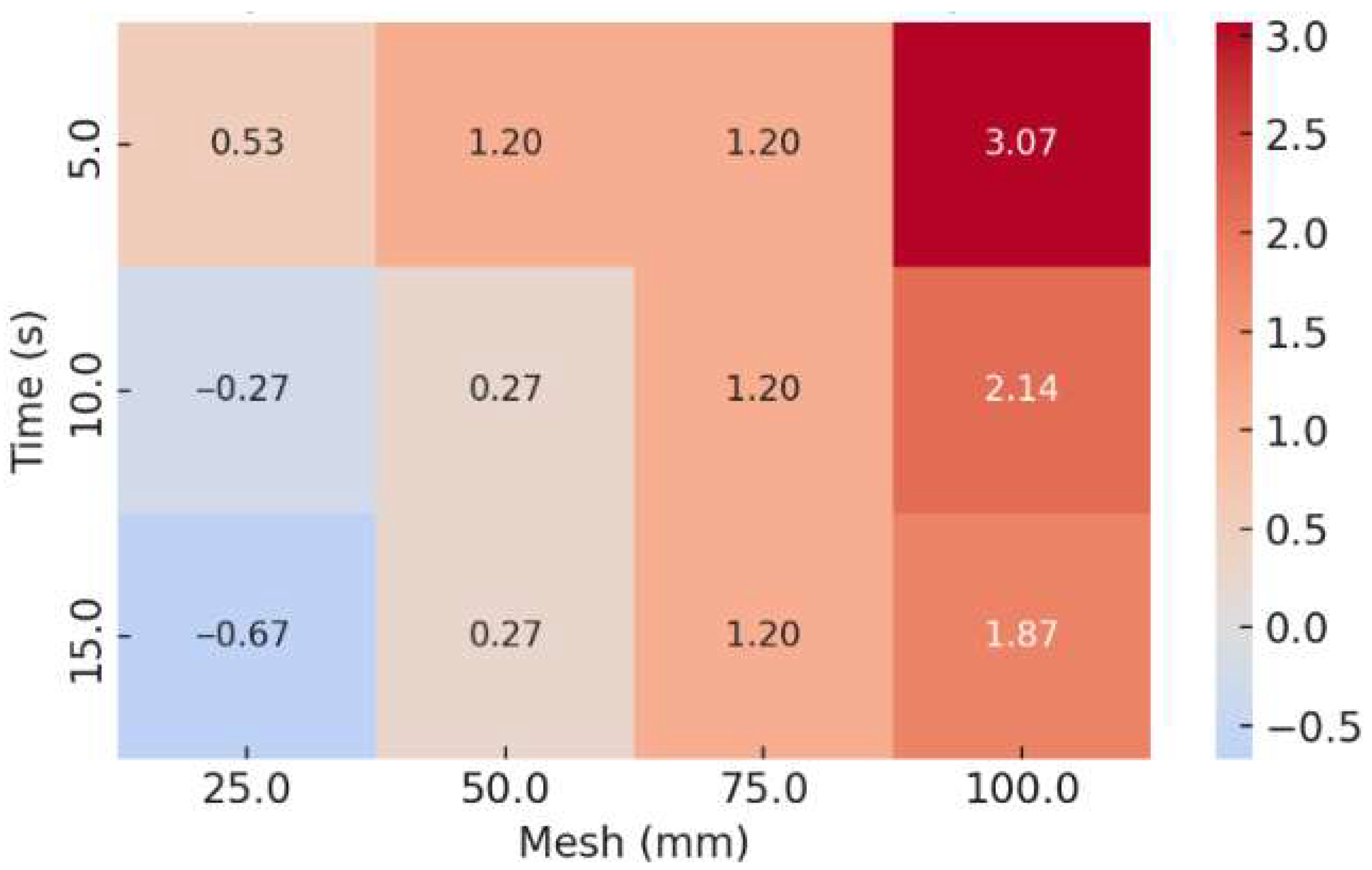
Since these factors directly affect the prediction of failure, it is important to evaluate how mesh size and time scaling influence the determination of critical temperature. The comparative results of critical temperature obtained at different mesh sizes and time scales are presented in Figure 5 and Figure 6. The critical temperature is defined as the temperature at which a column can no longer sustain its applied load. This condition is identified either when the internal axial force in the column reduces to the level of the originally applied load, or when the axial displacement returns to zero, indicating the loss of load-carrying capacity [20]. The bar chart in Figure 5 demonstrates that the predicted critical temperatures for all cases remain very close to the experimental value, with deviations generally within 2–3%. To further illustrate these deviations, Figure 6 specifically presents the percentage differences in critical temperature across various mesh sizes and time scales. The results indicate that all combinations of time scale and mesh size provide good agreement with the experimental data. Among these combinations, the 10 s–50 mm mesh configuration offers the optimum balance between computational efficiency and accuracy. While finer meshes (25 mm) and longer heating durations (15 s) slightly improve the prediction, they result in significantly higher computational cost. The 10 s–50 mm mesh model, therefore, represents the most efficient combination for capturing the critical temperature with high reliability.

3.1.3. Analysis Using Static General Step

The static analyses were carried out using the Abaqus standard solver. In order to overcome convergence difficulties arising from material softening and geometric instabilities at elevated temperatures, the automatic stabilisation option was activated with the default artificial energy dissipation factor of 0.0002. This technique introduces a very small amount of numerical damping into the system, which suppresses spurious oscillations in the Newton–Raphson iterations and prevents divergence of the solution. The selected value is sufficiently small to ensure that the artificial damping energy remains negligible compared to the strain energy, thereby stabilising the computation without influencing the physical response of the structure. The structural models were developed using both beam (line) elements and shell elements.
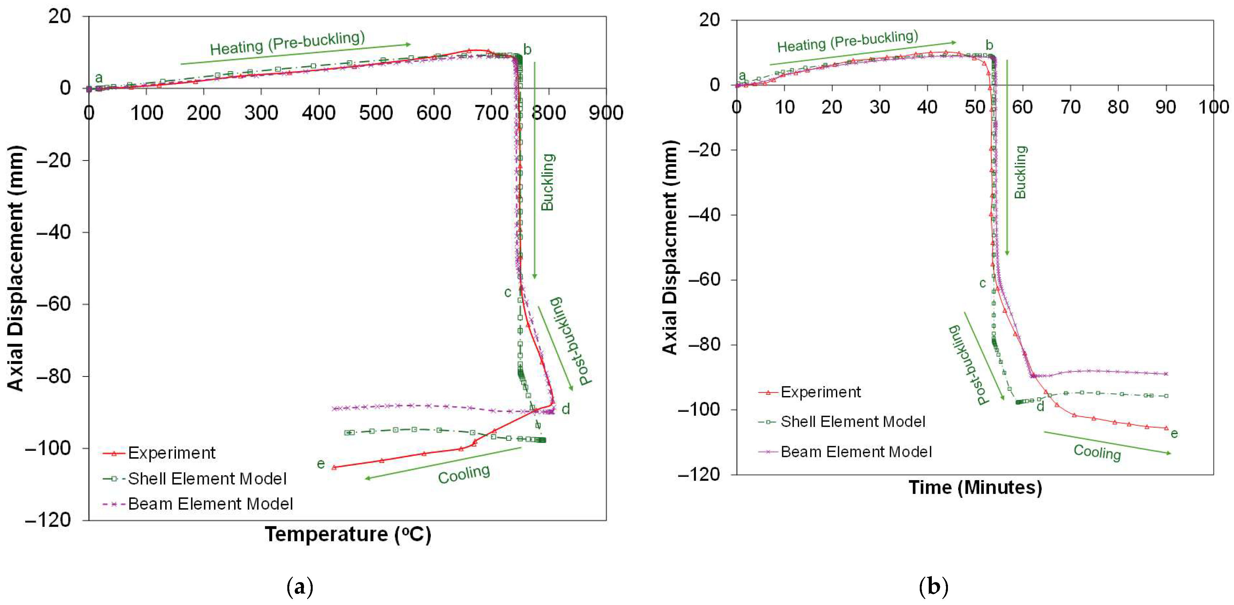
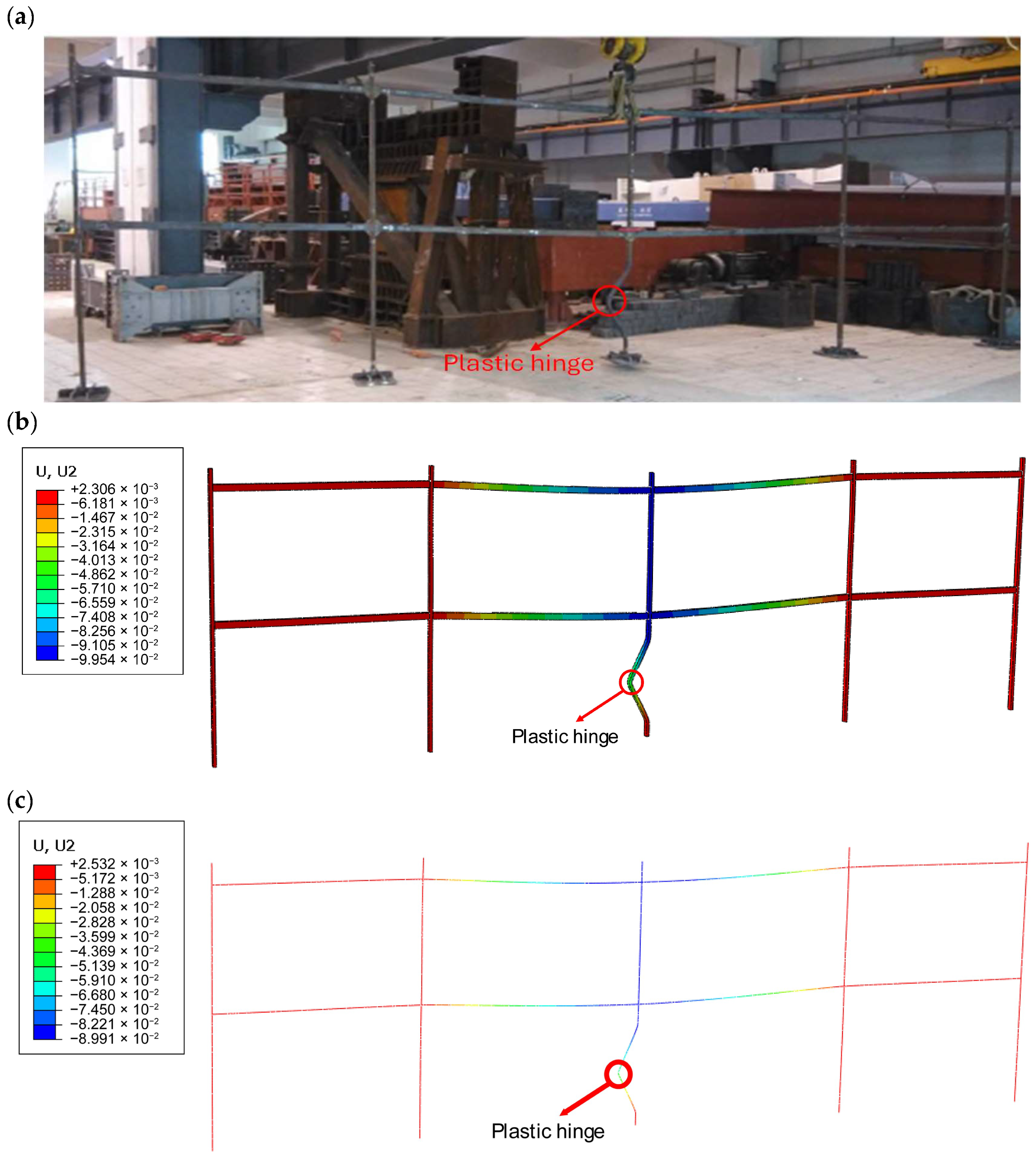
The mesh size for both the beam and shell models was fixed at 25 mm. The numerical predictions were compared with the experimental data as shown in Figure 7. The results demonstrate that both modelling approaches successfully capture the overall structural behaviour observed in the test, including the initial thermal expansion followed by significant contraction beyond the critical temperature. However, notable differences emerge in the predicted post-collapse axial shortening. The shell element model provides a closer agreement with the experimental response, whereas the beam element model slightly underestimates the total axial displacement. This difference can be attributed to the inherent capabilities of the element formulations. Shell elements are able to represent local flange and web buckling, sectional distortion, and detailed stress redistribution within the cross-section, all of which contribute significantly to the axial shortening of heated steel members. In contrast, beam elements represent only the global axial and flexural behaviour, averaging the sectional response and therefore failing to capture local instabilities that develop at high temperatures. Consequently, while beam models are computationally efficient and capture global behaviour, shell elements provide a more realistic representation of the collapse mechanism under fire exposure. Figure 8 shows the deformation of the frame observed during the experimental test and numerical simulations.

3.1.4. Comparative Analysis

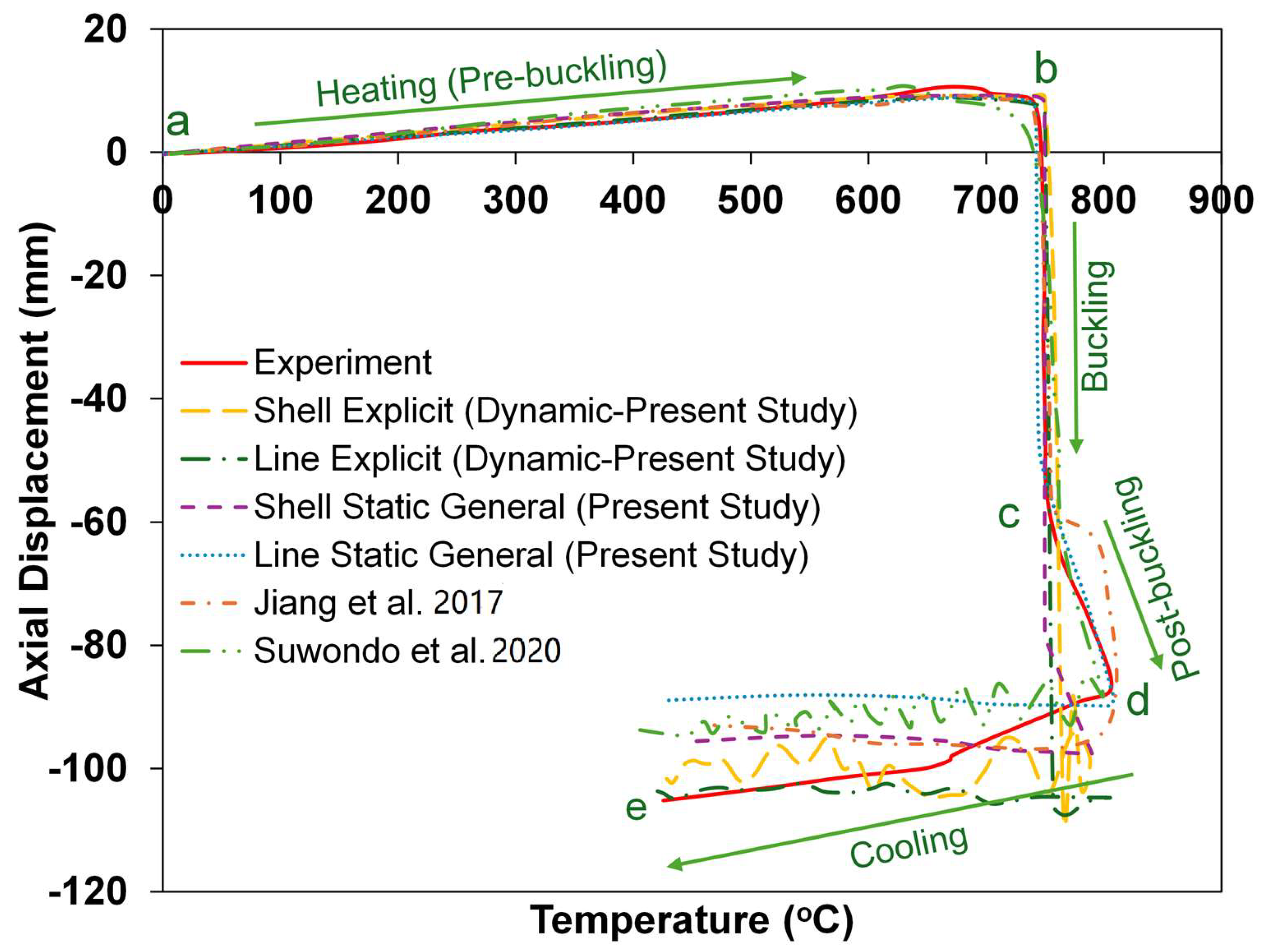
Figure 9 compares the simulation results from static and explicit analyses with experimental data and with previous computational studies by Jiang et al. [13] and Suwondo et al. [11,21]. The comparison shows that the axial displacement–temperature response is generally well captured by both line and shell element models under both static and dynamic analyses. The initial thermal expansion trend up to around 700 °C is consistently predicted across all approaches, aligning closely with the experimental curve. Beyond this critical temperature, a sharp contraction is observed, reflecting the loss of material strength and stiffness at elevated temperatures. The static general analyses with both shell and line elements provide smoother post-buckling responses and are in closer agreement with the experimental trend, whereas the dynamic explicit analyses exhibit oscillations after failure.
These oscillations arise due to the nature of the explicit time integration scheme, which is highly sensitive to sudden stiffness degradation and geometric instability during structural collapse. When the structure loses stability abruptly, the explicit method tends to capture rapid inertia-driven responses, resulting in numerical oscillations in the displacement history. Additionally, smaller time increments inherent in explicit formulations amplify this effect. Despite these oscillations, the dynamic explicit analyses remain valuable in capturing the collapse mechanism and failure mode, though static general approaches appear to yield more stable and representative displacement–temperature curves for post-buckling behaviour. Overall, the present study demonstrates that while both modelling strategies can reproduce the experimental response, the choice between static and dynamic formulations should consider the balance between numerical stability and the ability to simulate highly nonlinear collapse phenomena.
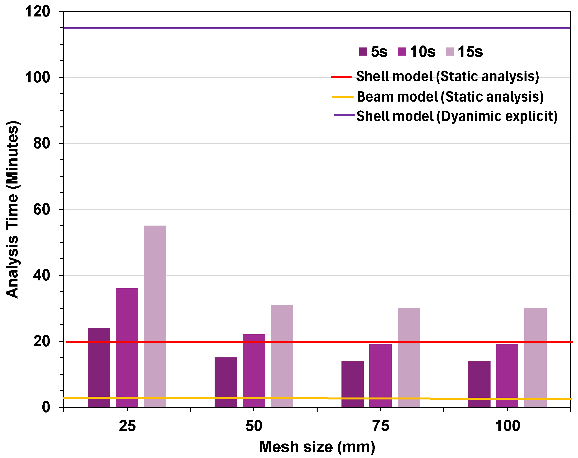
The bar charts shown in Figure 10 present the analysis time for the beam element model using explicit analysis at different mesh sizes and time increments. For comparison, the horizontal lines show the results from static and dynamic analyses: the shell model with a 25 mm mesh under static analysis, the beam model with a 25 mm mesh under static analysis, and the shell model with a 50 mm mesh under dynamic explicit analysis. Explicit analysis of the beam element model was performed for all mesh sizes, while for the shell model under explicit analysis, a 50 mm mesh was identified as the most efficient choice. As far as the beam element model is concerned, at a mesh size of 25 mm, the dynamic explicit analysis required the longest computational times. The 5 s step consumed approximately 23 min, increasing to nearly 37 min for the 10 s step and peaking at about 55 min for the 15 s step.
This indicates that finer meshes, when combined with longer step durations, substantially increase computational demand. For a mesh size of 50 mm, a noticeable reduction in computation time is observed. The dynamic explicit runs dropped to roughly 15 min (5 s), 22 min (10 s), and 31 min (15 s). This demonstrates the sensitivity of explicit analyses to mesh refinement, as coarser meshes reduce the number of elements and thereby shorten computation times. At a mesh size of 75 mm, the computational time for the explicit analysis continued to stabilise. The 5 s step required about 14 min, the 10 s step took 19 min, and the 15 s step took approximately 30 min. These values are lower than those observed for finer meshes but remain higher than the static beam model. When the mesh size reached 100 mm, the computational efficiency plateaued. The 5 s step consumed nearly 14 min, the 10 s step around 19 min, and the 15 s step roughly 30 min, closely mirroring the results from the 75 mm mesh. In comparison, the static analysis carried out on a mesh size of 25 mm required considerably less time, taking approximately 3 min to complete the analysis. This highlights a significant efficiency advantage. Comparing shell element model results, the static analysis required 20 min, and the dynamic explicit analysis required 115 min, which is around 6 times longer.
This comparative analysis reveals clear distinctions between static and dynamic approaches. Dynamic explicit analyses are highly sensitive to both mesh size and analysis step duration, with finer meshes and longer steps leading to significantly higher computation times. On the other hand, the static approach consistently offers the fastest analysis. Overall, for scenarios where detailed local responses are crucial, shell models or fine-mesh explicit analyses may be justified despite higher time costs. However, for broader structural performance assessments, beam models or coarser meshes provide a more efficient alternative without excessive computational burden.

3.2. Case Study 2

Rubert and Schaumann [9] conducted a series of investigations on frame assemblies. This study is one of the most important tests for understanding the behaviour of steel frames in fire conditions. It is considered a benchmark test for further research on the progressive collapse of frames and has been widely cited by many researchers [4,22,23]. In the experiments, a two-bay portal frame named ZSR Frame was tested. However, only one portal frame was heated, as shown in Figure 11. Based on the modelling strategies explored in the previous case study, both the shell and line element models produced comparable results in capturing the overall behaviour of steel frames under fire. Therefore, to impose simplicity and reduce computational effort, the ZSR frame is validated here using a line element model. A two-node B31 beam element was selected to construct the numerical model. The frame was fabricated with an IPE80 steel section, having a yield strength of 355 MPa and a modulus of elasticity of 210 GPa. The remaining modelling parameters were kept consistent with the methodology described in the previous section. The numerical results are validated against the deformations measured in the direction of the arrow at points U3 and U4. As observed in the previous case study, a mesh size of 50 mm was found to be suitable for accurately capturing the physical behaviour. Therefore, the same mesh size of 50 mm was adopted for this model.
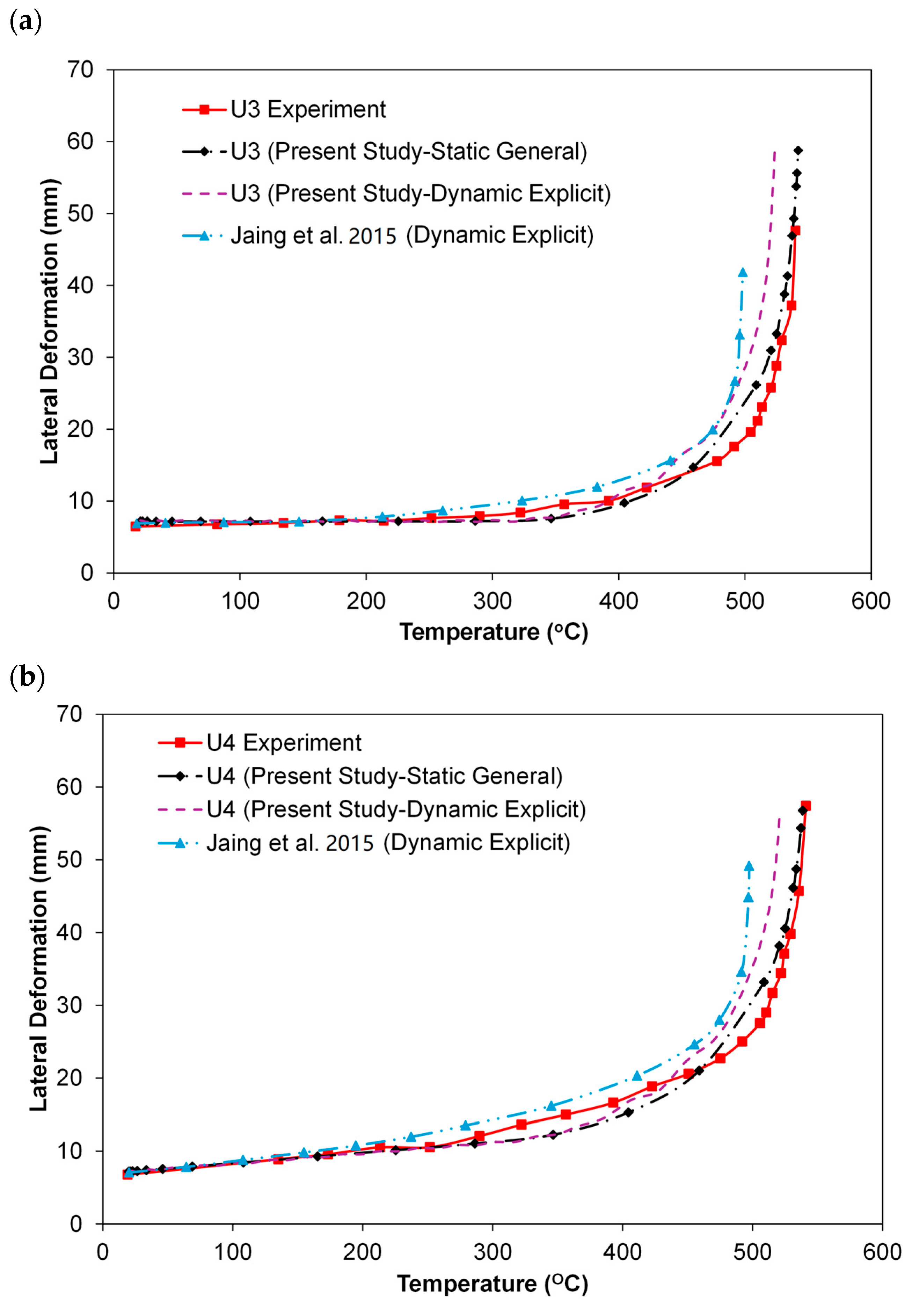
The results are shown in Figure 12a,b. The static analysis follows the experiment more closely. The dynamic explicit curves show a sudden jump in lateral deformation. The experimental results show relatively small and gradual lateral deformation. The static analysis is therefore able to reproduce the experimental trend more accurately, as it is formulated to follow equilibrium in a quasi-static manner. The dynamic explicit method, on the other hand, is more suitable for problems with large deformations, rapid instability, or collapse. In this case, the structure undergoes only limited deformation before failure, which reduces the advantage of using dynamic explicit analysis. As the material stiffness decreases with temperature, the explicit method produces sudden increments in deformation due to inertia effects and the absence of iterative equilibrium correction. This leads to the observed deviation from the experimental curve. Hence, for structural response under moderate deformation, static analysis provides closer agreement with experiments, while dynamic explicit analysis is more appropriate for cases involving severe instability and large deformation. This results in deviations from the experimental response, which are similar to those reported by Jiang et al. [22] using the same approach. Therefore, for problems with moderate deformation, static analysis provides closer agreement with experiments, while dynamic explicit analysis is more appropriate for capturing severe instability and large deformation.

4. Conclusions

This paper presents a detailed analysis procedure to model and validate experimental tests on steel frames subjected to fire, with a focus on accurately capturing the collapse mechanism using both the static general and dynamic explicit solvers. Based on the analyses, the following key outcomes are drawn:
  • Both dynamic explicit and static general analyses accurately captured the critical temperature of collapse, with deviations typically within 2–3% of experimental values, confirming the reliability of both approaches for predicting the start of the failure.
  • The dynamic explicit solver successfully reproduced the collapse mechanism and failure mode but exhibited oscillations after buckling due to inertia effects. In contrast, the static general method provided a smoother post-buckling response, better matching the experimental displacement temperature curve.
  • For dynamic explicit analyses, time scaling and mesh refinement are critical factors in calibrating the model with experimental results. While higher time scales and finer meshes lead to a significant increase in computational cost. The analysis time was observed to increase by nearly six to nine times when using shell elements compared to line elements under similar mesh and time-scale conditions.
  • The static general solver can capture collapse in both line and shell element models by introducing geometric imperfections and applying a standard artificial energy dissipation coefficient. This approach maintains quasi-static equilibrium and enables smoother tracing of the post-buckling response. Compared to explicit analysis, the computational time is reduced by approximately six to eighteen times, depending on whether shell or beam elements are used.
  • For validation against progressive collapse fire tests, the static general step with shell elements offers the most representative post-buckling response, while the dynamic explicit method with beam elements is more suitable for studying rapid instability and large deformations where inertia effects are critical.
  • Since the experimental validation in this study is limited to planar (2D) steel frames, it is recommended that the proposed modelling approaches be further evaluated on three-dimensional frame systems to establish their broader applicability. Future work should also incorporate material fracture and damage models, as well as investigate travelling fire scenarios, to enhance the practicality and extend the use of these methods in performance-based structural fire engineering.

Author Contributions

Conceptualisation, R.K.; methodology, R.K. and N.A.; software, R.K.; validation, R.K.; formal analysis, R.K.; investigation, R.K.; resources, N.A. and A.N.; writing—original draft preparation, R.K.; writing—review and editing, R.K. and N.A.; supervision, N.A. and A.N. All authors have read and agreed to the published version of the manuscript.

Funding

This research received no external funding.

Institutional Review Board Statement

Not applicable.

Informed Consent Statement

Not applicable.

Data Availability Statement

Data will be available on request.

Acknowledgments

The Authors would like to thank Ulster University for providing research facilities and the necessary tools to perform this research.

Conflicts of Interest

The authors declare no conflicts of interest.

References

  1. Cao, Y.; Jiang, J.; Lu, Y.; Chen, W.; Ye, J. Progressive collapse of steel structures exposed to fire: A critical review. J. Constr. Steel Res. 2023, 207, 107985. [Google Scholar] [CrossRef]
  2. Agarwal, A.; Varma, A.H. Fire Induced Progressive Collapse of Steel Building Structures. In Structures Congress; ASCE: Washington, DC, USA, 2012; pp. 235–246. [Google Scholar]
  3. Agarwal, A.; Varma, A.H. Fire induced progressive collapse of steel building structures: The role of interior gravity columns. Eng. Struct. 2014, 58, 129–140. [Google Scholar] [CrossRef]
  4. Shakeri, K.; Aval, S.M.M.; Akrami, V.; Khansoltani, E. Progressive Collapse Analysis of Intermediate Moment-Resisting Steel Frame under Fire-Induced Column Failure. J. Perform. Constr. Facil. 2023, 37, 04023034. [Google Scholar] [CrossRef]
  5. Roy, K.; Lim, J.B.; Lau, H.H.; Yong, P.; Clifton, G.; Johnston, R.P.; Wrzesien, A.; Mei, C.C. Collapse behaviour of a fire engineering designed single-storey cold- formed steel building in severe fires. Thin-Walled Struct. 2019, 142, 340–357. [Google Scholar] [CrossRef]
  6. Jiang, J.; Lu, Y.; Dai, X.; Li, G.-Q.; Chen, W.; Ye, J. Disproportionate collapse of steel-framed gravity buildings under travelling fires. Eng. Struct. 2021, 245, 112799. [Google Scholar] [CrossRef]
  7. Rackauskaite, E.; Kotsovinos, P.; Jeffers, A.; Rein, G. Structural analysis of multi-storey steel frames exposed to travelling fires and traditional design fires. Eng. Struct. 2017, 150, 271–287. [Google Scholar] [CrossRef]
  8. Rackauskaite, E.; Kotsovinos, P.; Lange, D.; Rein, G. Collapse Initiation and Mechanisms for a Generic Mul-ti-storeySteel Frame Subjected to Uniform and Travelling Fires. Int. J. High-Rise Build. 2021, 10, 265–283. [Google Scholar] [CrossRef]
  9. Rubert, A.; Schaumann, P. Structural steel and plane frame assemblies under fire action. Fire Saf. J. 1986, 10, 173–184. [Google Scholar] [CrossRef]
  10. Li, G.-Q.; Wang, P.; Wang, Y. Behaviour and design of restrained steel column in fire, Part 1: Fire test. J. Constr. Steel Res. 2010, 66, 1138–1147. [Google Scholar] [CrossRef]
  11. Suwondo, R.; Cunningham, L.; Gillie, M.; Bailey, C. Progressive collapse analysis of composite steel frames subject to fire following earthquake. Fire Saf. J. 2019, 103, 49–58. [Google Scholar] [CrossRef]
  12. Jiang, B.; Li, G.-Q.; Li, L.; Izzuddin, B.A. Experimental Studies on Progressive Collapse Resistance of Steel Moment Frames under Localized Furnace Loading. J. Struct. Eng. 2018, 144, 04017190. [Google Scholar] [CrossRef]
  13. Jiang, B.; Li, G.-Q.; Li, L.; Izzuddin, B. Simulations on progressive collapse resistance of steel moment frames under localized fire. J. Constr. Steel Res. 2017, 138, 380–388. [Google Scholar] [CrossRef]
  14. Abaqus, Finite Element Modelling Programme and Standard User’s Manual; Version 6.14; SIMULIA. Dassault Systèmes Simulia Corp.: Providence, RI, USA, 2016; Available online: http://130.149 89 (2018) v6 (accessed on 1 July 2024).
  15. Sam, V.S.; Anand, N.; Iswarary, A.; Ananthi, B.G.; Andrushia, D. Influence of heating cooling regime on the buckling capacity of galvanized iron-based cold-formed steel columns with welded connections. J. Infrastruct. Preserv. Resil. 2025, 6, 13. [Google Scholar] [CrossRef]
  16. EN 1993-1-1:2005 Eurocode 3; Design of Steel Structures–Part 1-1: General Rules and Rules for Buildings. European Committee for Standardization: Brussels, Belgium; John Wiley & Sons: Hoboken, NJ, USA, 2005.
  17. Kumar, R.; Alam, N.; Nadjai, A. Integrated analysis of loading eccentricity on response of a column under travelling fire. In Proceedings of the 13th International Conference on Structures in Fire, Coimbra, Portugal, 19–21 June 2024. [Google Scholar]
  18. Kumar, R.; Alam, N.; Nadjai, A. Behaviour of steel columns under fire: A review on experimental testing and numerical investigation supplemented with computational case studies validation. J. Struct. Fire Eng. 2025, 16, 427–457. [Google Scholar] [CrossRef]
  19. Wang, Y.C. Postbuckling Behavior of Axially Restrained and Axially Loaded Steel Columns under Fire Conditions. J. Struct. Eng. 2004, 130, 371–380. [Google Scholar] [CrossRef]
  20. Yang, J.; Xia, Y.; Wang, W.; Al-Azzani, H. Fire resistance of axially restrained Q690 H-shaped welded steel columns: Test, simulation and design. J. Constr. Steel Res. 2021, 177, 106413. [Google Scholar] [CrossRef]
  21. Suwondo, R.; Cunningham, L.; Gillie, M. Modelling progressive failure of steel moment frames exposed to localised fire. IOP Conf. Ser. Earth Environ. Sci. 2020, 426, 012046. [Google Scholar] [CrossRef]
  22. ManojKumara, C.; Sachin, V.; Suresh, N.; Naveen, B. The collapse mechanism of steel framed structure exposed to parametric design fire and travelling fire scenarios. Mater. Today Proc. 2023. [Google Scholar] [CrossRef]
  23. Jiang, B.; Li, G.-Q.; Usmani, A. Progressive collapse mechanisms investigation of planar steel moment frames under localized fire. J. Constr. Steel Res. 2015, 115, 160–168. [Google Scholar] [CrossRef]
Figure 1. Schematic diagram of the test frame [12].
Fire 08 00420 g001
Figure 2. Temperature profile recorded during the test [12].
Fire 08 00420 g002
Figure 3. Numerical model created in Abaqus: (a) shell element model, (b) beam element model.
Fire 08 00420 g003
Figure 4. Axial displacement of column (a) 5 s time scale; (b) 10 s time scale; (c) 15 s time scale.
Fire 08 00420 g004
Figure 5. Variation in critical temperature corresponds to mesh size at different time scales.
Fire 08 00420 g005
Figure 6. Heatmap showing the percentage difference in critical temperature with respect to mesh size and time scaling.
Fire 08 00420 g006
Figure 7. Comparison of axial displacement response under fire: (a) temperature vs. axial displacement, (b) time vs. axial displacement.
Fire 08 00420 g007
Figure 8. Deformation of frame: (a) test picture [12], (b) shell element model, (c) line element model.
Fire 08 00420 g008
Figure 9. Comparative analysis of the current study simulation results with past studies [13,21].
Fire 08 00420 g009
Figure 10. Comparative analysis of simulation time for dynamic explicit and static.
Fire 08 00420 g010
Figure 11. ZSR Frame.
Fire 08 00420 g011
Figure 12. Comparison of experimental and numerical results [23].
Fire 08 00420 g012
Disclaimer/Publisher’s Note: The statements, opinions and data contained in all publications are solely those of the individual author(s) and contributor(s) and not of MDPI and/or the editor(s). MDPI and/or the editor(s) disclaim responsibility for any injury to people or property resulting from any ideas, methods, instructions or products referred to in the content.