1. Introduction
The rapid development of urbanization and the energy industry have led to the accelerated construction of long-distance oil and gas pipelines worldwide [
1]. The United States and Russia, for example, have extensive networks totaling 800,000 km and 400,000 km, respectively. These pipelines function as essential arteries for energy transportation and are crucial for national economic and social development. However, long-distance oil and gas pipelines face challenges due to their complex environments, continuous operation, and potential hazards, such as toxicity, flammability, and explosiveness. Factors like third-party damage, corrosion, pipeline defects, and natural disasters can lead to ruptures and leaks, resulting in severe consequences like fires, poisoning, and environmental pollution [
2]. Accumulated oil and gas from leaks can reach explosive concentrations, posing a significant risk of explosion accidents when ignited. The resulting shock wave overpressure and high-temperature flames can cause catastrophic damage to nearby facilities and personnel. Additionally, the mobility of gas explosion mixtures can lead to long-distance explosion incidents with widespread damage [
3]. The incident on 22 November 2013, in Qingdao City, Shandong Province, China, in which an underground oil pipeline ruptured—resulting in the leakage of approximately 380 tons of crude oil into a municipal drainage culvert and subsequent explosion—had devastating consequences. Tragically, 62 people lost their lives, 9 were injured, and the incident led to economic losses amounting to CNY 700 million. This incident serves as a stark reminder of the risks associated with long-distance oil and gas pipelines, especially since they often traverse densely populated areas. In the event of an accident, the potential for serious casualties and significant economic losses is a grave concern.
The concealed nature of the urban underground pipeline system, which serves as the primary method for oil and gas transmission, poses challenges for real-time monitoring of oil and gas leakage risks. The complex tunnel structure and numerous obstacles within the pipeline system further complicate risk assessment and the prediction of oil and gas explosion effects in the event of accidental ignition [
4]. This complexity hinders effective prevention and control of leakage and explosion accidents in oil and gas pipelines. However, significant progress has been made by researchers in studying the explosion hazards related to oil and gas pipeline systems, yielding important research findings. For instance, Li et al. [
5] conducted extensive full-scale underground space gas explosion experiments and developed a risk assessment method for underground space explosions. They introduced a comprehensive ‘leakage–diffusion–aggregation–ignition–explosion’ full-chain accident evolution model that considers the likelihood, consequences, and correction factors of underground space explosions. This model has been applied to 24,830 high-risk underground spaces, providing valuable insights for enhancing safety measures in urban underground pipeline systems. Yang et al. [
6] conducted a study on the explosion characteristics of hydrogen-doped natural gas in a 200-m public tunnel. Their findings revealed that the maximum overpressure peak at both ends of the tunnel exceeded that in the middle. Mishra [
7] employed a semi-empirical model and a CFD model to analyze underground gas pipeline failures, gas diffusing explosions, and fires, focusing on the impact of the volume blockage ratio on gas boundary layer flow stability. The study highlighted that high thermal radiation from surface methane pool fires was a significant factor in fatalities. Cao et al. [
8] conducted experiments on gas explosion propagation and release at different concentrations using a 66.5-m pipeline explosion propagation test system. Their results showed that as the propagation distance increased, the pipeline’s overpressure initially decreased and then increased, forming an approximate ‘V’ shape. Zhang et al. [
9] utilized an artificial neural network prediction model to rapidly estimate the gas explosion load by considering factors such as ignition point location, methane volume and concentration, and obstacles present. When the methane volume exceeds 300 m
3, detonation typically occurs in the public tunnel, with the presence of obstacles having an increasing impact on the explosion load. The artificial neural network-based explosion overpressure model can effectively depict the explosion overpressure and duration in each section of the tunnel. Zhao et al. [
10] established an experimental apparatus to replicate the natural gas explosion process in a public tunnel and investigated the effects of the explosion chamber length and pressure relief conditions on the flame behavior during the gas explosion. It was observed that the auxiliary facilities in the explosion chamber did not create a large-scale recirculation zone, but instead induced small-scale turbulence. As the length of the explosion chamber increased, the maximum overpressure initially rose and then declined. Moreover, higher pressure relief intensity led to a more comprehensive development of the flame within the tunnel and resulted in increased overpressure generation. Xu et al. [
11] introduced a disaster chain model for gas leakage and explosions in public tunnels, examining the progression from gas leakage to explosion. The model is applied to determine the explosion hazard zone by considering the dynamic evolution of gas leakage. Although various approaches have been employed to assess the risk of leakage and explosion in underground oil and gas pipelines, the spatial scope of these studies remains constrained. Underground long-distance oil and gas pipelines spanning tens of kilometers between adjacent sites pose a unique challenge. The substantial increase in oil and gas volume within super-large-scale tunnel spaces results in distinct explosion evolution patterns and disaster effects. In contrast, existing research on oil and gas explosions in underground environments has predominantly been conducted at the laboratory scale, making it challenging to effectively elucidate the fundamental aspects of large-scale, long-distance oil and gas pipeline leakage and explosion incidents.
When an explosion incident occurs in an underground long-distance oil and gas pipeline, the explosion energy propagates through the tunnel wall and soil medium, subsequently affecting the foundation and surface structures. When the explosion stress wave reaches the foundation, it induces stress responses that could potentially cause deformation or displacement. Consequently, the surface structures also exhibit corresponding reactions [
12]. Therefore, it is crucial to consider the potential impact damage and vibration risks posed by the leakage and explosion of underground oil and gas pipelines on critical target facilities, such as adjacent pipelines and surface structures. Liu et al. [
13] developed a three-dimensional, nonlinear, finite element model of a tunnel pipeline subjected to explosions, investigating the impact of factors like leakage area and explosion center distance on the damage extent of adjacent pipelines during explosions. The findings highlight the significant influence of the explosion center distance on the damage to crude oil pipelines under explosion loads, demonstrating the effectiveness of explosion-proof walls in preventing pipeline failures. Xin et al. [
14] conducted experimental investigations on the dynamic responses of deep-buried, straight-wall circular arch structures under explosion-induced ground impact. Analysis of the measured data revealed that the peak acceleration of underground structures following an explosion can reach 2400 g. Li et al. [
15] conducted a series of explosion tests utilizing explosives and cement mortar blocks, revealing a notable increase in peak particle velocity (PPV) on the ground with higher charge densities. Wang et al. [
16] employed LS-DYNA software to analyze the dynamic response of an underground cavern structure considering three parts—the vault side, arch side, and wall side—along with seven different explosion source combinations. The study indicated that as the number of explosion sources increased, the peak displacement, PPV, and surrounding rock damage also escalated. Mussa [
17] utilized ANSYS LS-DYNA 15.0 software to investigate the damage characteristics in underground box-frame tunnels resulting from TNT explosions of varying masses. The study confirmed that the pressure wave propagates into the soil in hemispherical waves. Notably, when the soil depth was 4, 6, or 8 m, the tunnel experienced minimal damage. In summary, numerous scholars have conducted experimental and numerical investigations on the response of surface or underground structures to explosive impact loads, yielding valuable insights. However, it appears that there is a gap in the research focusing on the structural response and vibration risk analysis of surface residential buildings in the context of leakage and explosions from underground gas pipelines. This area of study becomes especially crucial when underground long-distance pipelines traverse densely populated residential areas.
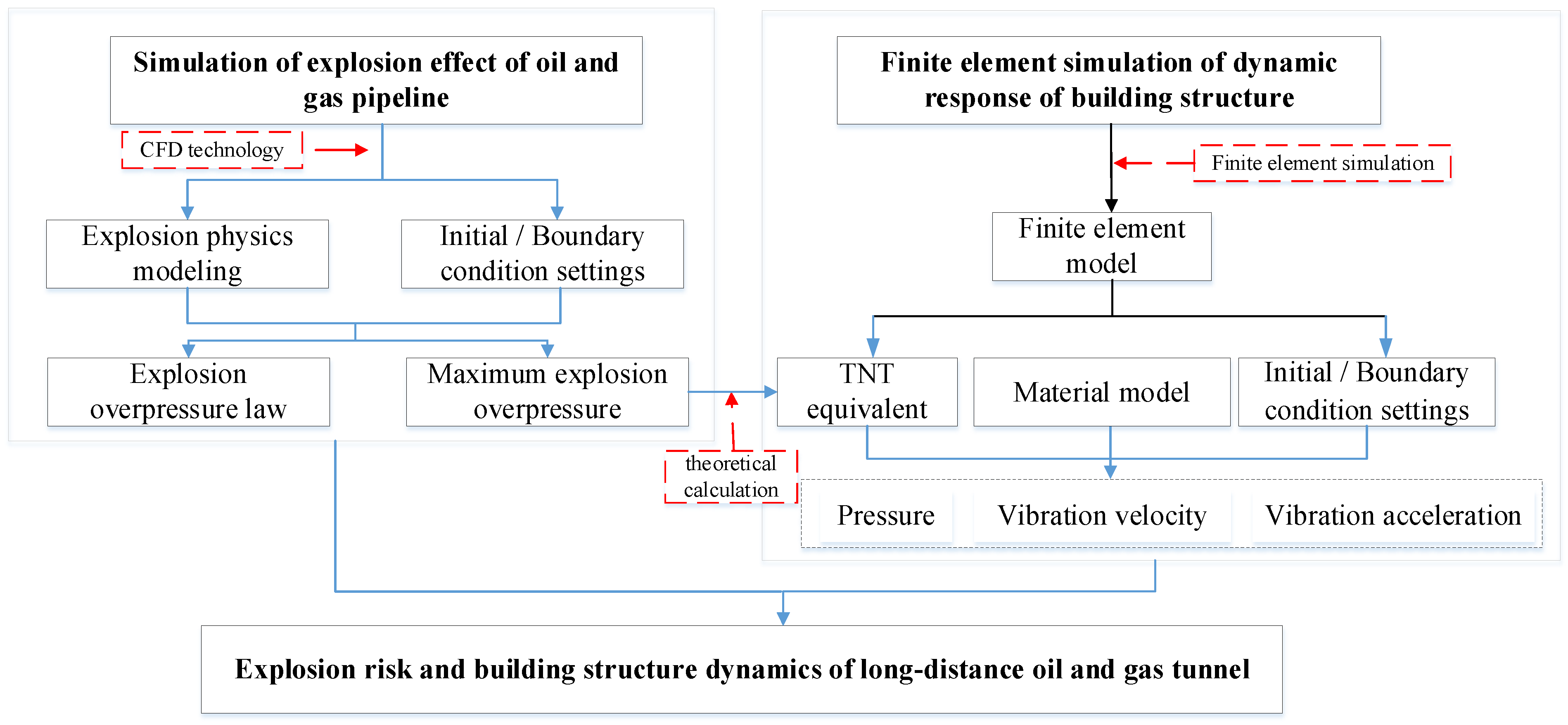
In this paper, a segment of the oil and gas long-distance pipeline stretching from Dalian to Shenyang in China serves as the focal point of the research. By leveraging computational fluid dynamics technology and finite element analysis methods, the study constructed simulation models for the effects of natural gas explosions in full-scale, ultra-long tunnel spaces and the dynamic response of building structures under explosion impacts. The investigation included numerical analyses of the disaster effects of oil and gas explosion overpressure for tunnel lengths of 4000 m, 8000 m, and 16,000 m, along with the establishment of an equivalent conversion between maximum explosion peak overpressure and TNT mass through theoretical formulas. Consequently, the study delved into the explosion shock response process and vibration risk patterns of ground building structures under varying soil depth conditions. The research findings are valuable in proposing and strengthening risk prevention and control measures for underground, long-distance natural gas pipeline leakage and explosions, thereby providing valuable insights for the safety analysis of vital protective structures. These research ideas are illustrated in
Figure 1.
2. Explosion Modeling of Long-Distance Natural Gas Pipeline
The AutoReaGas simulation program is primarily utilized for simulating the temporal and spatial evolution characteristics of gas explosions and disasters, specifically tailored for highly congested and confined spaces [
18]. Its limitations are as follows: (1) it does not support all types of reactions, especially those involving higher-order reactions or complex chemical reaction mechanisms; (2) for large systems or systems with complex dynamic behaviors, simulation may be very time-consuming; and (3) the lack of an in-depth understanding of chemical reaction kinetics may lead to misunderstandings of simulation results. Nevertheless, these limitations do not impede the simulation of propagation characteristics specific to a single natural gas explosion within an extended tunnel space. Zhang and Pang from the Beijing Institute of Technology [
19,
20] employed this software to conduct numerical modeling and simulation of coal dust roadway explosions on a 100-m scale, validating the accuracy of AutoReaGas in simulating explosions in high aspect ratio tunnel models. Consequently, this study utilizes the AutoReaGas software as a tool to perform numerical calculations and evaluation analyses of the explosion consequences associated with underground long-distance oil and gas pipelines. The simulations are based on fundamental equations of fluid mechanics, specific turbulence and combustion models, and time-space discrete equations. The relevant computational models have been effectively applied to the tracing of explosion accidents and the assessment of explosion risks [
21,
22,
23].
AutoReaGas software mainly uses the finite volume method to solve a series of equations, such as the mass conservation equation, the momentum conservation equation, and the energy conservation equation. With the help of Cartesian tensor representation, it can be expressed as follows:
Mass conservation equation:
Momentum conservation equation:
Energy conservation equation:
where
x is the space coordinate,
t is the time coordinate,
ρ is the density,
u is the velocity,
p is the static pressure;
i and
j are the coordinate directions.
E is the specific internal energy and
E =
CVT +
mfu Hc.
τij is a viscous stress tensor, which can be expressed as
where the turbulent viscosity coefficients
μt =
Cμ ρk2/
ε,
k,
ε are turbulent kinetic energy and turbulent kinetic energy dissipation rate, respectively. The model constant is
Cμ = 0.09 m
2/s, and
δij is the Kronecker symbol. Turbulence, as a key factor in the mechanism of gas explosions, is mainly simulated by the
k-
ε model. It consists of a continuous equation that includes turbulent kinetic energy
k and turbulent kinetic energy dissipation rate
ε. The turbulence model can be described as
where
C1 and
C2 are constants, which are 1.44 and 1.79, respectively. The heat added in the process of a gas explosion is provided by combustion. The combustible gas is transformed into combustion products through a one-step reaction model. The mathematical expression of the conservation equation of gas fuel mass fraction is as follows:
where the gas burning rate
Rfu = Ct ρ (
st2/Γ
fu)
Rmin,
Rmin is the minimum value of fuel mass fraction, the oxygen mass fraction and the product mass fraction,
Ct is the flame velocity constant, and the value is 40. For detailed parameter definitions and units, please refer to the naming table.
2.1. Gas Explosion Physical Model
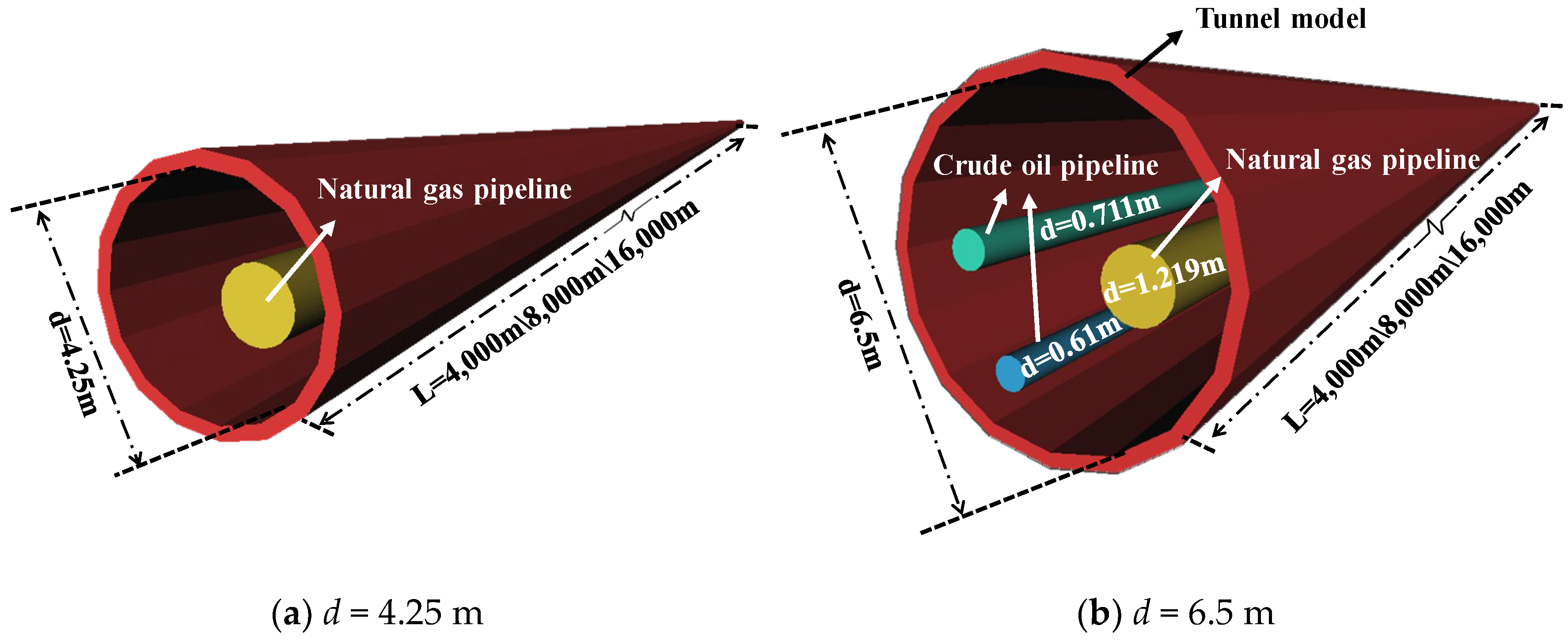
The focus of this study is on an ultra-long natural gas/crude oil pipeline buried underground between Dalian and Shenyang in China. This pipeline is of particular interest due to its potential impact regarding the explosion consequences of oil and gas pipelines, given its location beneath urban buildings. The construction method for this pipeline primarily involved the use of a shield tunneling scheme. The shield employs deep burial techniques to traverse residential areas, with the tunnel being buried at depths ranging from 20 to 40 m below the surface. The shield tunnel spans a total length of 16,000 m. When considering the laying of one pipeline or of three pipelines within the shield tunnel, the inner diameters (
d) of the tunnel are 4.25 m and 6.5 m, respectively. The cross-sections and structures of the two tunnels are depicted in
Figure 2. In the smaller tunnel, a 1.219 m natural gas pipeline is installed, while the larger tunnel accommodates a 1.219 m natural gas pipeline along with two crude oil pipelines. The inner diameters of the two crude oil pipelines are 0.711 m and 0.61 m, respectively.
The study encompassed the development of two physical models of underground tunnels based on their actual dimensions utilizing the AutoReaGas pre-processing tools, as depicted in
Figure 3. To simulate the most severe consequences of an oil and gas explosion in the tunnel, the models were constructed without concrete filling, thereby maximizing the presence of oil and gas volume. For enhanced modeling efficiency, only three pipelines were physically represented in accordance with the original sizes, omitting small-scale solid obstacles like welding trolleys and gantry cranes that have minimal impact on the explosion effects. During an oil and gas explosion, the shaft structure serves as a means of pressure relief, thereby reducing the explosion pressure within the tunnel. To account for the most hazardous explosion scenario, the physical model represents a completely enclosed tunnel space without considering the presence of shaft structures. This design choice ensures that explosion energy is not released or dissipated during the propagation process, leading to the continuous accumulation of explosion effects within the tunnel model.
To account for the presence of multiple valve chambers within the tunnel, the 16,000 m tunnel was segmented into sections of varying lengths. As a result, three tunnel models were constructed with lengths of 4000 m, 8000 m, and 16,000 m, each featuring inner diameters of 4.25 m and 6.5 m. This approach led to the creation of six tunnel explosion simulation scenarios, aimed at investigating the impact of different tunnel diameters and lengths on oil and gas explosion effects. In order to capture the time-history evolution and peak values of the explosion load within the tunnel, a total of 33 gauges were strategically placed along the geometric center line of the model. These gauges were evenly distributed at intervals of 125 m, 250 m, and 500 m in the 4000 m, 8000 m, and 16,000 m models, respectively, as illustrated in
Figure 4.
2.2. Initial Boundary Condition and Grid Scheme
The computational domain’s wall boundaries were characterized as static, smooth, and non-slip, indicating that there was no exchange of mass, momentum, or energy between the internal tunnel system and the external environment during the progression of an oil and gas explosion. Based on previous research findings [
24], which indicate that a longer flame development path correlates with greater variability in explosion energy and more severe explosion effects, a spherical ignition source with a radius of 0.015 m was positioned at one end of the tunnel in the numerical simulation. This setup allows for a comprehensive observation of the explosion propagation dynamics within the tunnel. The calculation time step was set at 1 × 10
−5 s, and convergence was achieved when the iterative residuals of all control equations fell below 1 × 10
−5 s. To account for gas turbulence resulting from actual pipeline leakage in the tunnel, the dimensionless turbulence constant in the numerical calculation was adjusted to 70.
Grid density plays a crucial role in determining the accuracy of simulations and the computational time required. Higher grid densities lead to more accurate simulation results, but also significantly increase the computational time. Conversely, lower grid densities may result in insufficient detail representation and rough calculation outcomes. In a study conducted by Hu et al. [
25] using AutoReaGas software, a grid independence test was performed on a gas explosion experiment in a 45 m
3 volume room. The results showed that with a grid size of 0.1 m, the relative error between the simulated explosion overpressure and experimental data was less than 10%, indicating acceptable numerical calculation accuracy for large-scale gas explosion transient flow field problems. However, the tunnel models in this study can reach lengths of up to 16,000 m. Using a 0.1 m cube grid size to divide such long tunnels would result in hundreds of millions of grids, significantly reducing computational efficiency. To address this challenge, this study employs scale similarity theory to enlarge the grid size by a factor of ten, using a 1 m grid size for division. This approach enhances computational efficiency while ensuring the accuracy of numerical calculations.
According to the scaling similarity theory of explosion simulation, simulated explosion behaviors should exhibit similarity when two numerical models share the same scaling ratio in terms of grid size and physical dimensions. In this study, the grid size was reasonably increased from 0.1 m to 1 m, adhering to both the geometric scaling similarity principle and the physical scaling similarity principle. Building upon the theoretical analysis results, a comparison was conducted to validate the scientific rigor and accuracy of the 1 m grid size. The simulated explosion overpressure and relative error were compared at various positions within a tunnel with an inner diameter of 4.25 m and a length of 4000 m, using grid sizes of 1 m and 0.7 m. The comparison results are presented in
Table 1, indicating that the relative error of the explosion overpressure peak at different tunnel positions falls within 10%, signifying an acceptable level of error. In conclusion, this study demonstrates that utilizing a 1 m grid size for division not only saves computational time but also maintains calculation accuracy, as confirmed through a grid independence test using a 1 m cube grid. The grid division layout is illustrated in
Figure 5.
In order to reduce the influence of the boundary of the computational domain on the numerical solution of the explosion, several meters are extended along the three directions of the models X\Y\Z, respectively. Finally, six kinds of computational domain sizes (length × width × height) under the combination of two tunnel inner diameter areas (4.25 m, 6.5 m) and three tunnel lengths (4000 m, 8000 m, 16,000 m) were derived, which were the following: (1) 4000 m × 8.5 m × 8.5 m; (2) 8000 m × 8.5 m × 8.5 m; (3) 16,000 m × 8.5 m × 8.5 m; (4) 4000 m × 13.6 m × 13.6 m; (5) 8000 m × 13.6 m × 13.6 m; (6) 16,000 m × 13.6 m × 13.6 m. The final total number of grids were 392,098, 784,196, 1,568,392, 648,162, 1,296,324 and 2,592,648.
Based on this investigation’s findings [
26,
27], the components of natural gas and crude oil in the pipeline are detailed in
Table 2 and
Table 3, respectively. The tables reveal that methane constitutes the largest proportion of both natural gas and crude oil vapor, accounting for 92% and 80%, respectively. In scenarios where oil and gas leak simultaneously in the tunnel, methane emerges as the primary component of the explosive mixture. Therefore, it is assumed that the tunnel is filled with a static methane-air mixture during ignition. To account for the most severe conditions, the volume concentration of methane-air mixture in the tunnel was set at 9.5% (equivalent concentration).
3. Numerical Analysis of Natural Gas Explosion Effect in the Tunnel
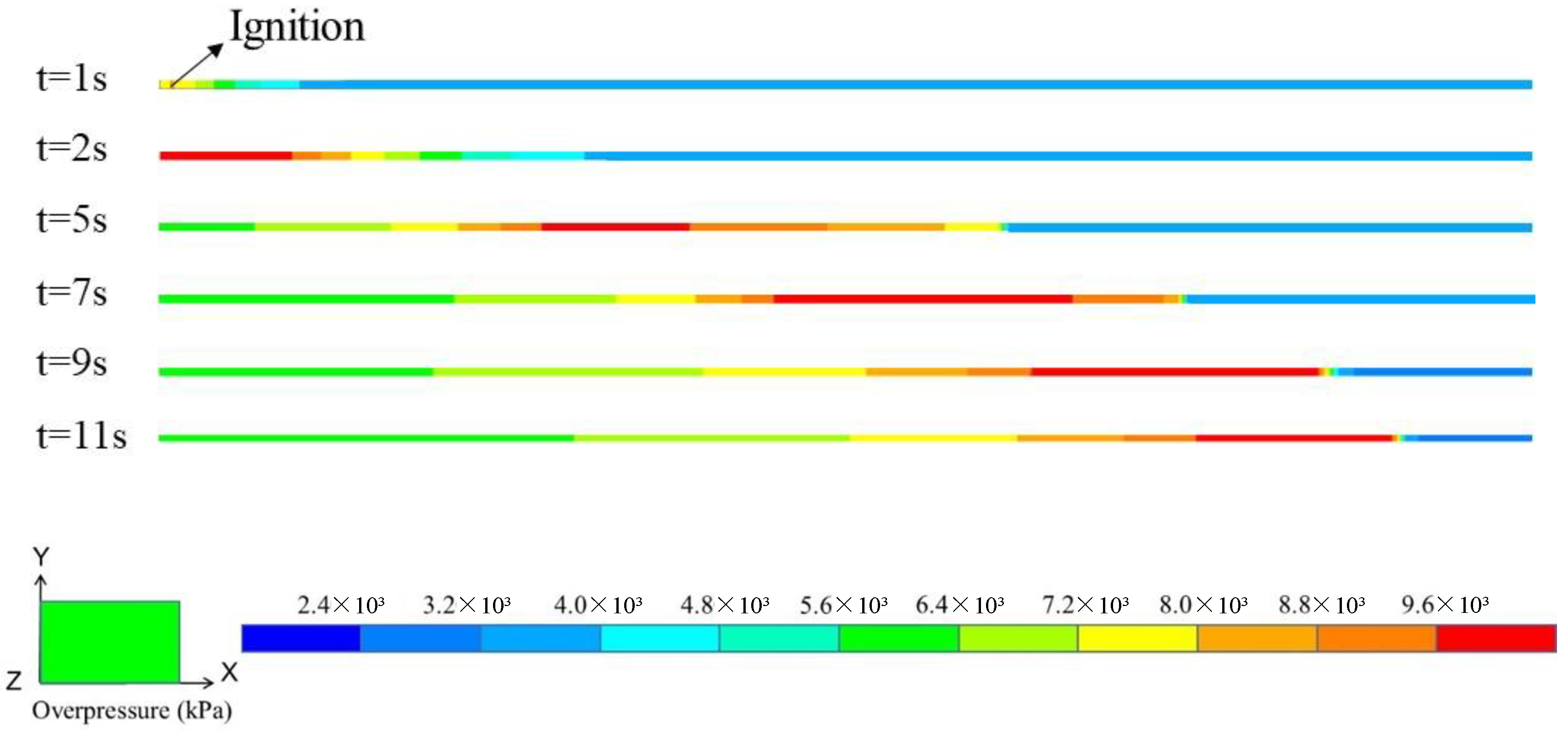
Figure 6 illustrates the evolution process of natural gas explosion overpressure within the tunnel space. As the initial shock wave of the explosion traveled towards one end of the tunnel containing unburned gas, the violent combustion reaction zone (depicted in red) gradually expanded before diminishing. The propagation of the explosion shock wave exhibited stages of rapid growth followed by a slower decline, a pattern that aligns with the findings of the LPG/DME deflagration experiment conducted by Zhang et al. [
28]. This observation indicates that the shock wave undergoes intense development in the front and middle sections of the tunnel. Due to the influence of reflected waves, the acceleration of the explosion flame at the tunnel’s end decelerated or even hindered the explosion’s progression, leading to a reduction in the speed of explosion propagation and a decrease in the extent of the violent reaction zone.
An analysis of the evolution of peak overpressure of natural gas explosion with distance in the tunnel, as shown in
Figure 7, revealed a pattern in which the peak overpressure initially increases and then decreases as the tunnel distance extends from the ignition point. This evolution can be categorized into distinct stages of acceleration and deceleration in the propagation of the shock wave along the tunnel.
- (1)
The primary reason for the acceleration stage of the shock wave was attributed to the generation of turbulence factors along the path of explosion propagation. Previous studies [
29,
30] had emphasized the critical role of turbulence as a key parameter in assessing explosion risks within obstacle spaces, with turbulence being predominantly caused by the flame itself and the presence of obstacles. Upon initial ignition, the density contrast between the combustion gas and unburned gas gives rise to Taylor instability between the two fronts, leading to accelerated flame propagation. The unstable acceleration of the flame disrupted the precursor shock wave, further enhancing turbulence levels and reinforcing the self-accelerating effect of the flame. Additionally, the presence of oil and gas pipelines within the tunnel acted as obstacles. As the precursor shock wave encountered these obstacles, a significant amount of turbulence and vortices were generated in the rear area adjacent to the obstacles, prompting the shock wave to transition into an accelerated propagation state.
- (2)
The deceleration stage occurred in the region near the tail end of the tunnel space, where the precursor shock wave continues to compress the mixed gas in the remaining closed tunnel space. According to the first law of thermodynamics, as the precursor shock wave propagated it compressed the remaining gas, leading to a decrease in volume, an increase in internal energy, and a rise in temperature. This increase in temperature intensified the molecular thermal motion, elevating the static pressure of the remaining gas. Consequently, there was a quasi-static work trend of outward expansion of the remaining gas, which inhibited the rapid propagation of the shock wave, causing it to transition into the deceleration propagation stage.
Upon examining
Figure 7, when the tunnel length was 4000 m the maximum explosion peak overpressure occurred in the middle of the tunnel. This observation suggested that the expansion of compressed air at the front of the precursor shock wave within the tunnel exerted a heightened inhibitory effect on the shock wave propagation. As the tunnel length increased, the position of the maximum explosion peak overpressure lagged behind, typically falling within the range of 3000 m to 4000 m.
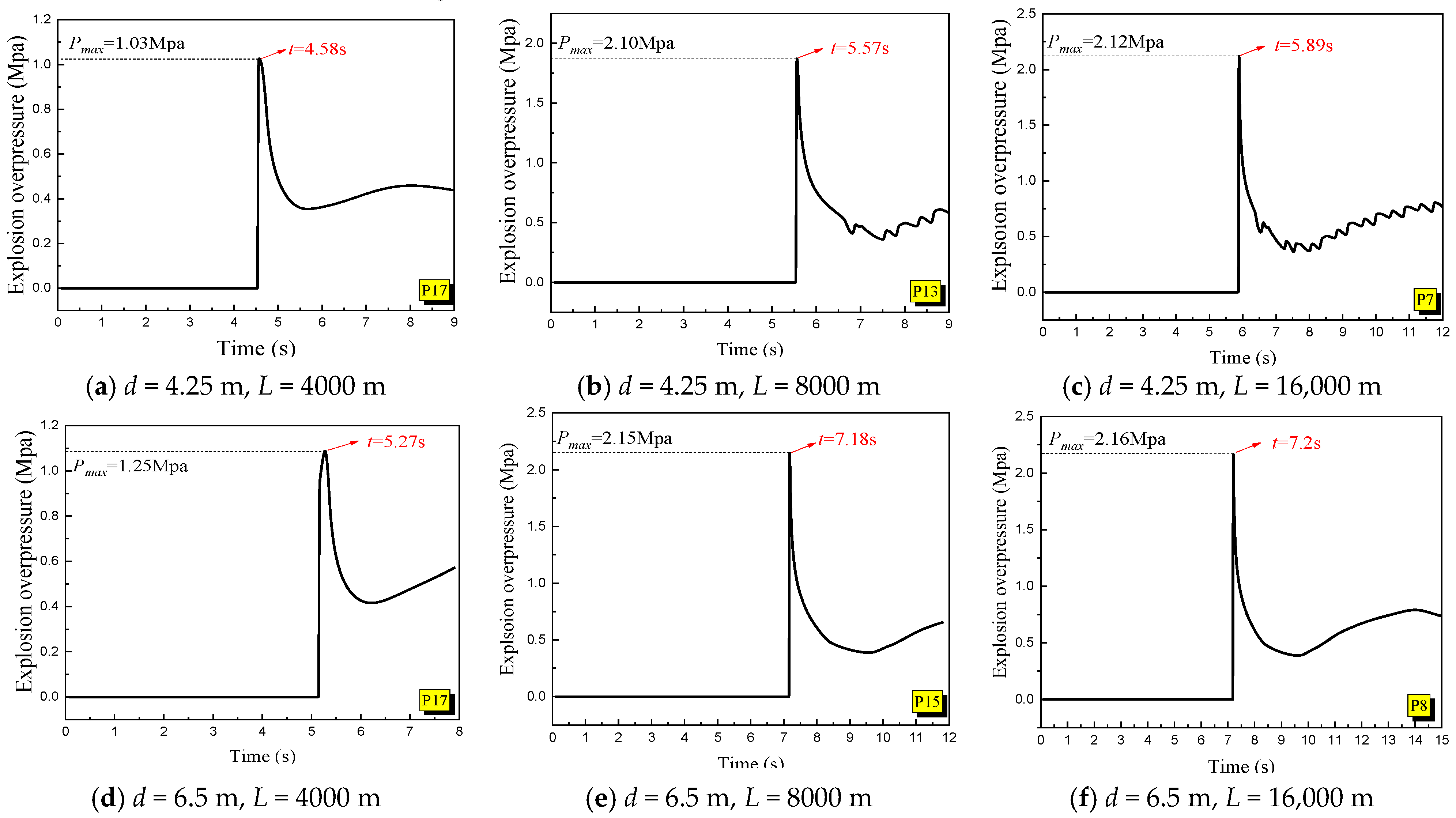
Figure 8 displays the maximum explosion pressure-time curves for tunnel diameters of 4.25 m and 6.5 m across various tunnel lengths. The graph highlights a distinct pressure peak (
Pmax) on the explosion overpressure curve, which occurred when the explosion flame area reached its maximum extent. As the tunnel length increased, the internal maximum explosion peak overpressure gradually rose, and the peak arrival time progressively delayed. Notably, when the tunnel lengths reached 8000 m and 16,000 m, the disparity between the maximum overpressure peak and its arrival time diminished significantly. This observation suggested that the explosion effect does not exhibit a substantial difference with the increase in natural gas volume. The analysis performed indicated that in the case of extensive tunnel lengths, the cumulative contribution of a specific point explosion to the energy at distant locations decreased with distance. Therefore, for tunnel space explosions characterized by high aspect ratios, where the space extends infinitely in a single direction, the maximum explosion overpressure at a particular position may not demonstrate significant variations.
4. Finite Element Modeling of Building Dynamic Response under Explosion Impact
AUTODYN is a widely utilized, explicit finite element analysis software program that specializes in simulating explosion scenarios, with a particularly strong military background. It is primarily employed for analyzing the response and coupling of fluids, gases, and solids under high-speed impacts or extreme loads. AUTODYN excels in solving highly nonlinear mechanical problems and is instrumental in simulating explosion effects in various applications. The software is extensively utilized in warhead design, underwater explosion studies, space protection research, and simulation analyses within the explosion domain. Researchers have leveraged AUTODYN in numerous studies to investigate the response of structures to explosions and to simulate shock wave interactions with buildings and other elements. For instance, Ma et al. utilized AUTODYN to simulate the interaction between explosion shock waves and buildings, validating the calculation results through experiments [
31]. Wang utilized AUTODYN to analyze the dynamic response and damage of reinforced concrete frame columns under explosion scenarios, providing insights into the behavior and damage patterns of the columns [
32].
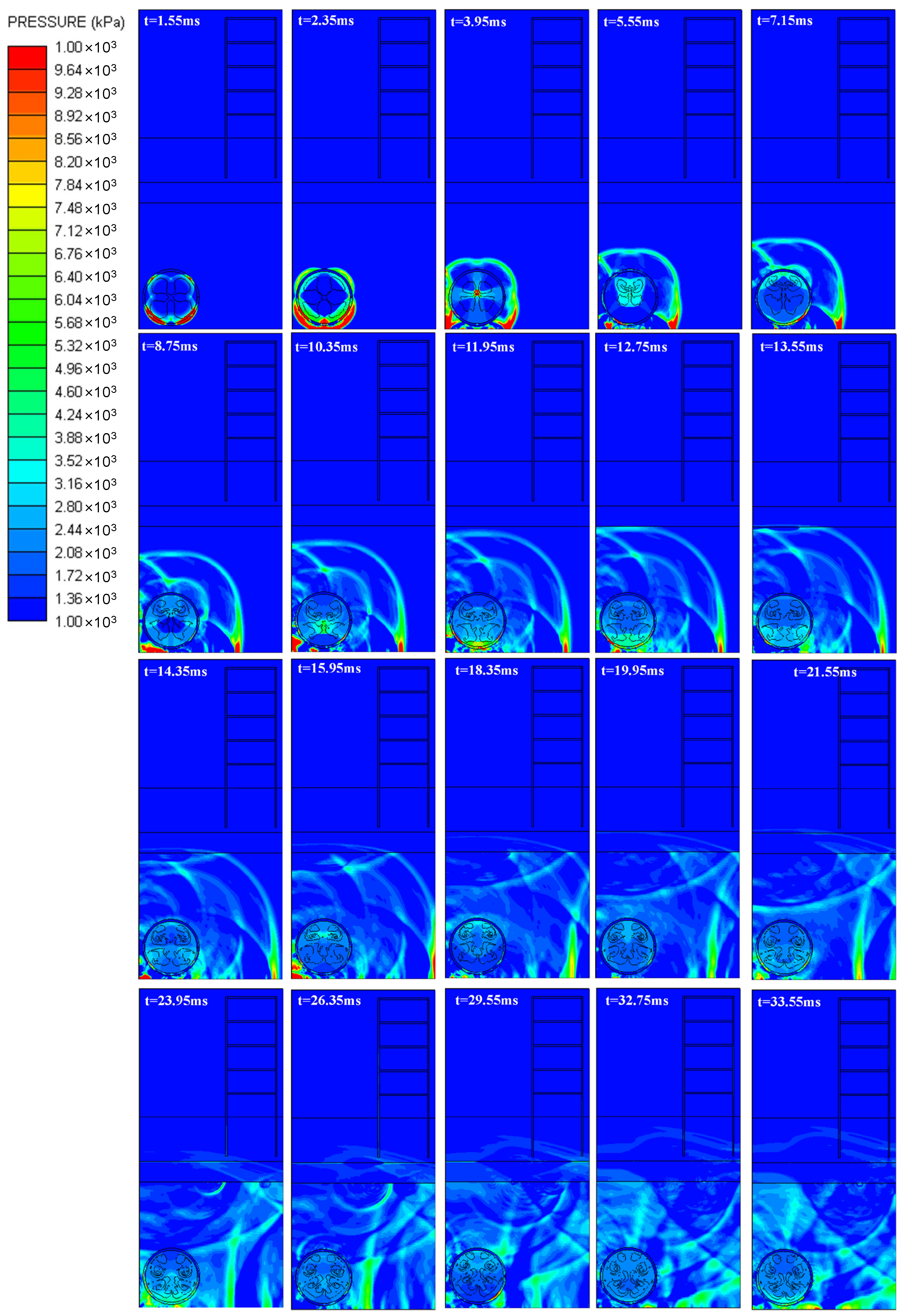
In a study aimed at exploring the dynamic response and vibration risks of ground building structures under natural gas explosion loads, a numerical analysis model of the explosion response of building structures was developed using the finite element analysis software AUTODYN. The propagation process of the explosion wave was simulated using the Euler method, while the structural entities were modeled based on the Lagrange method. This approach allowed for a comprehensive analysis of the explosion wave propagation in the soil induced by a natural gas pipeline explosion in a tunnel, enabling the assessment of the response risks associated with vibration velocity and acceleration on ground buildings.
4.1. Finite Element Modeling
4.1.1. Simulation Analysis Model
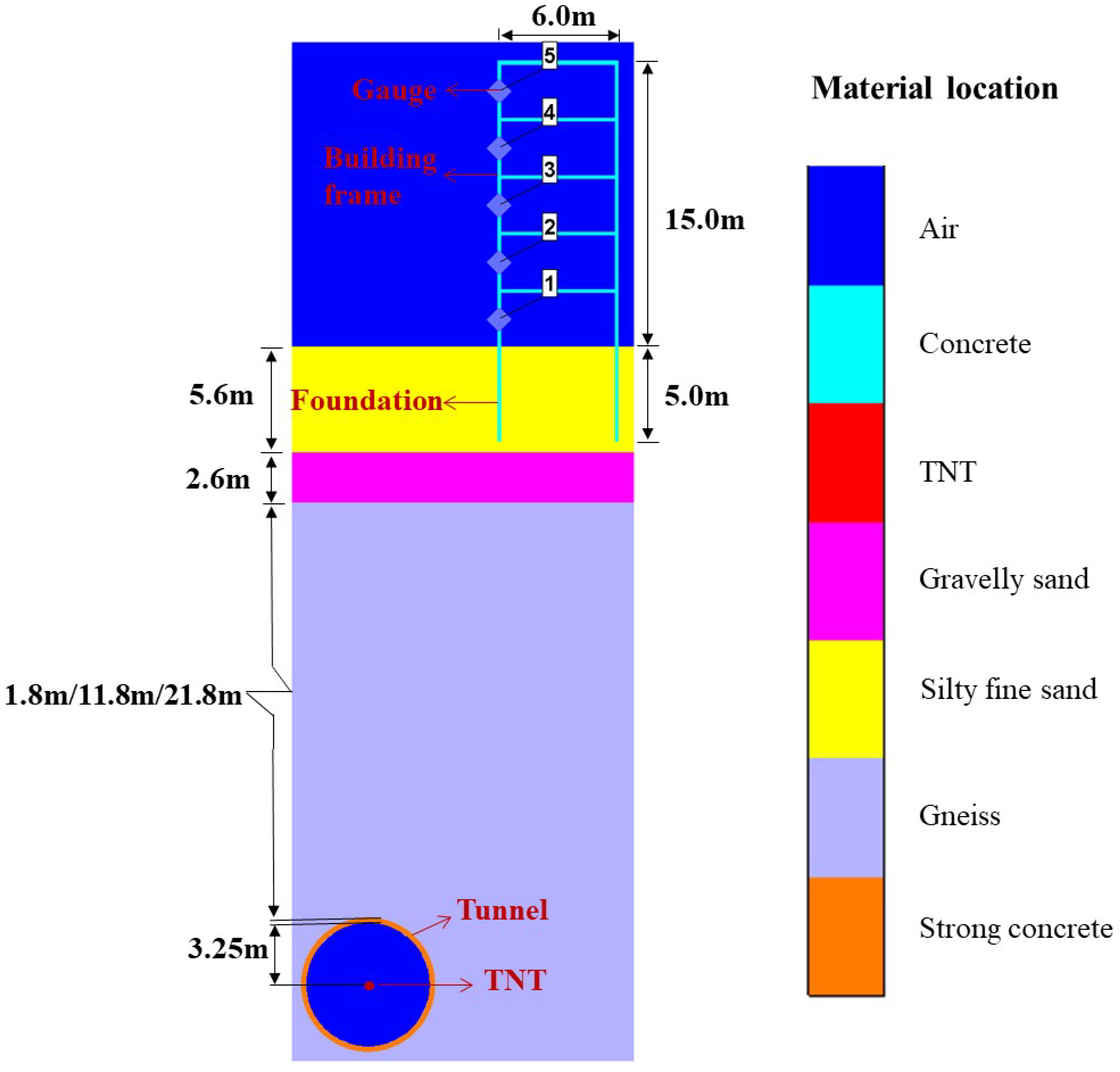
In this study focusing on the physical characteristics of long-distance natural gas pipeline tunnels and adjacent ground building structures, a two-dimensional simulation model of explosion response was established using AUTODYN software. The model comprised various components, including the explosion source, tunnel, fine sand, gravel sand, gneiss, building, and air, as illustrated in
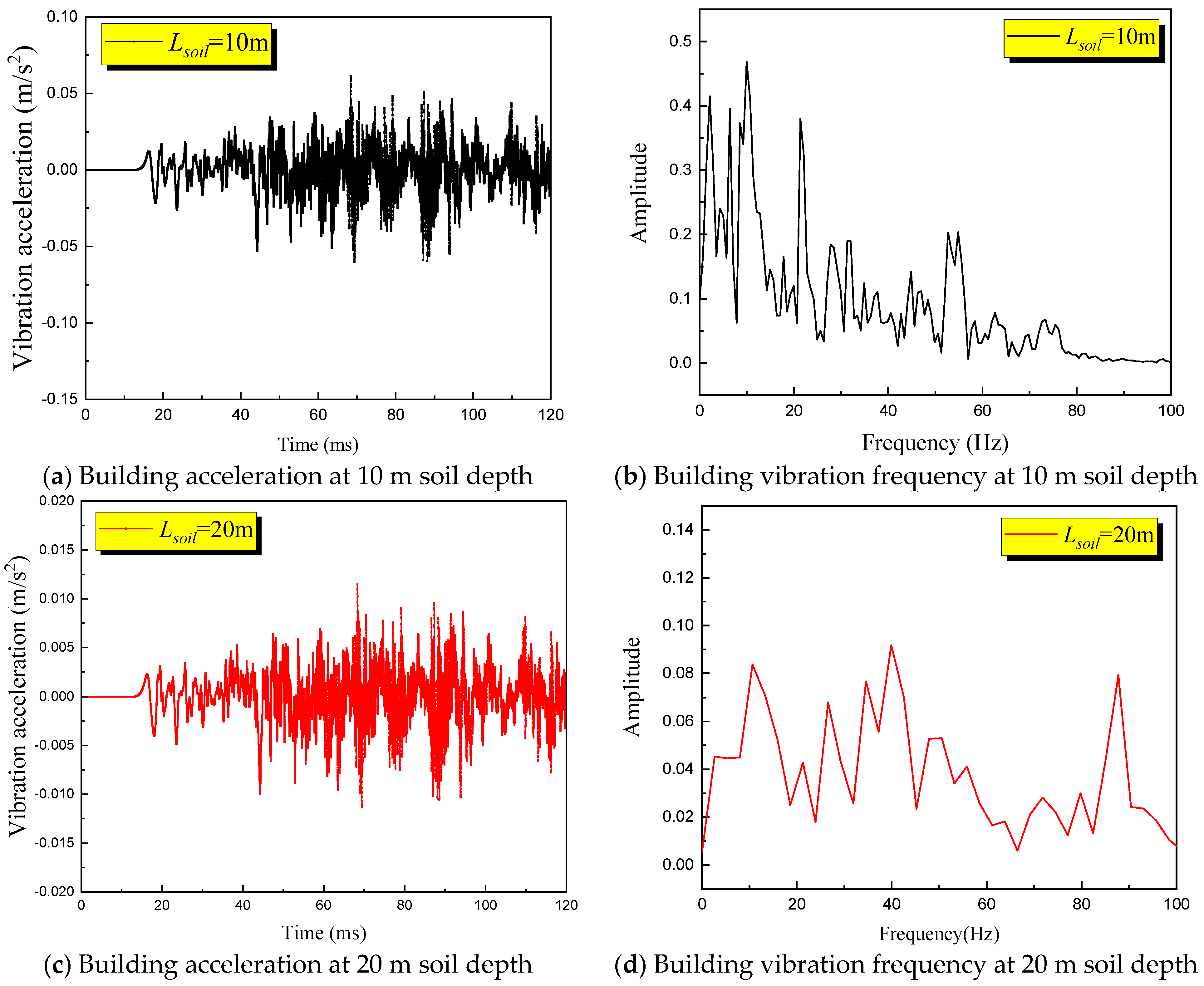
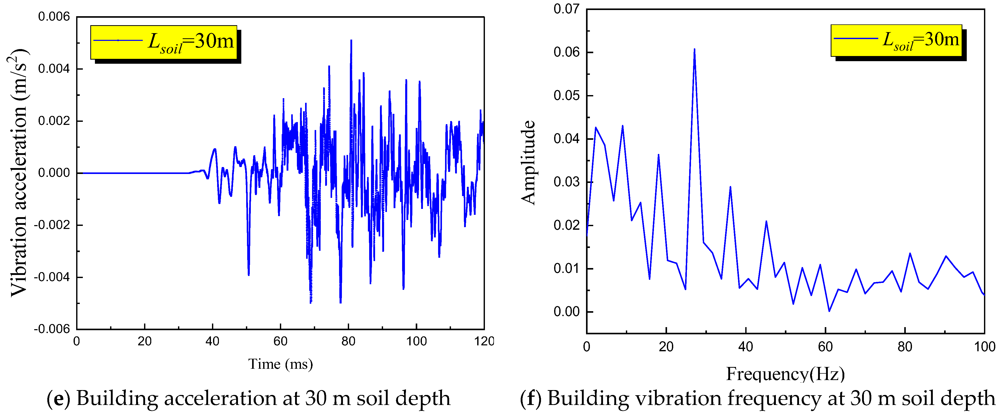
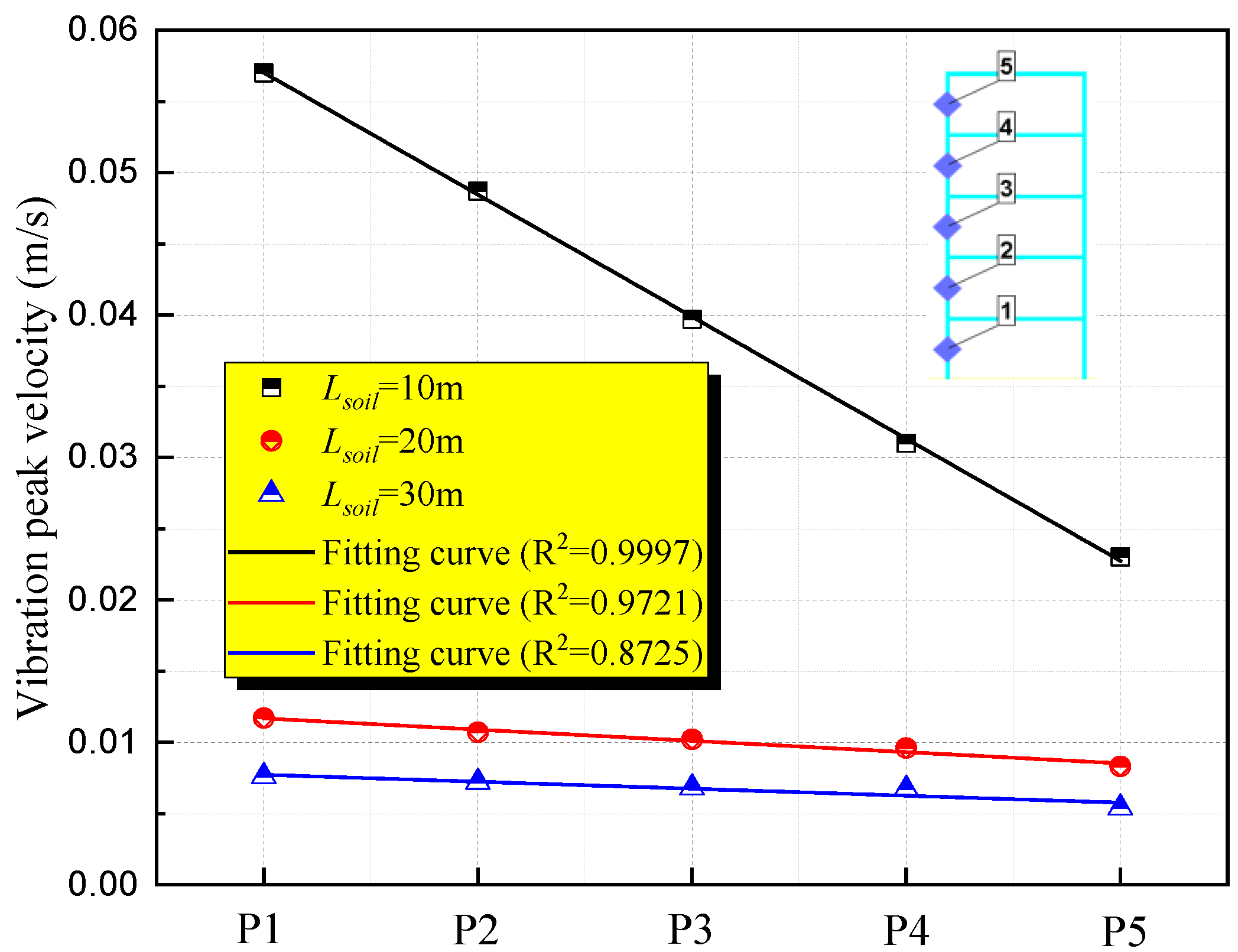
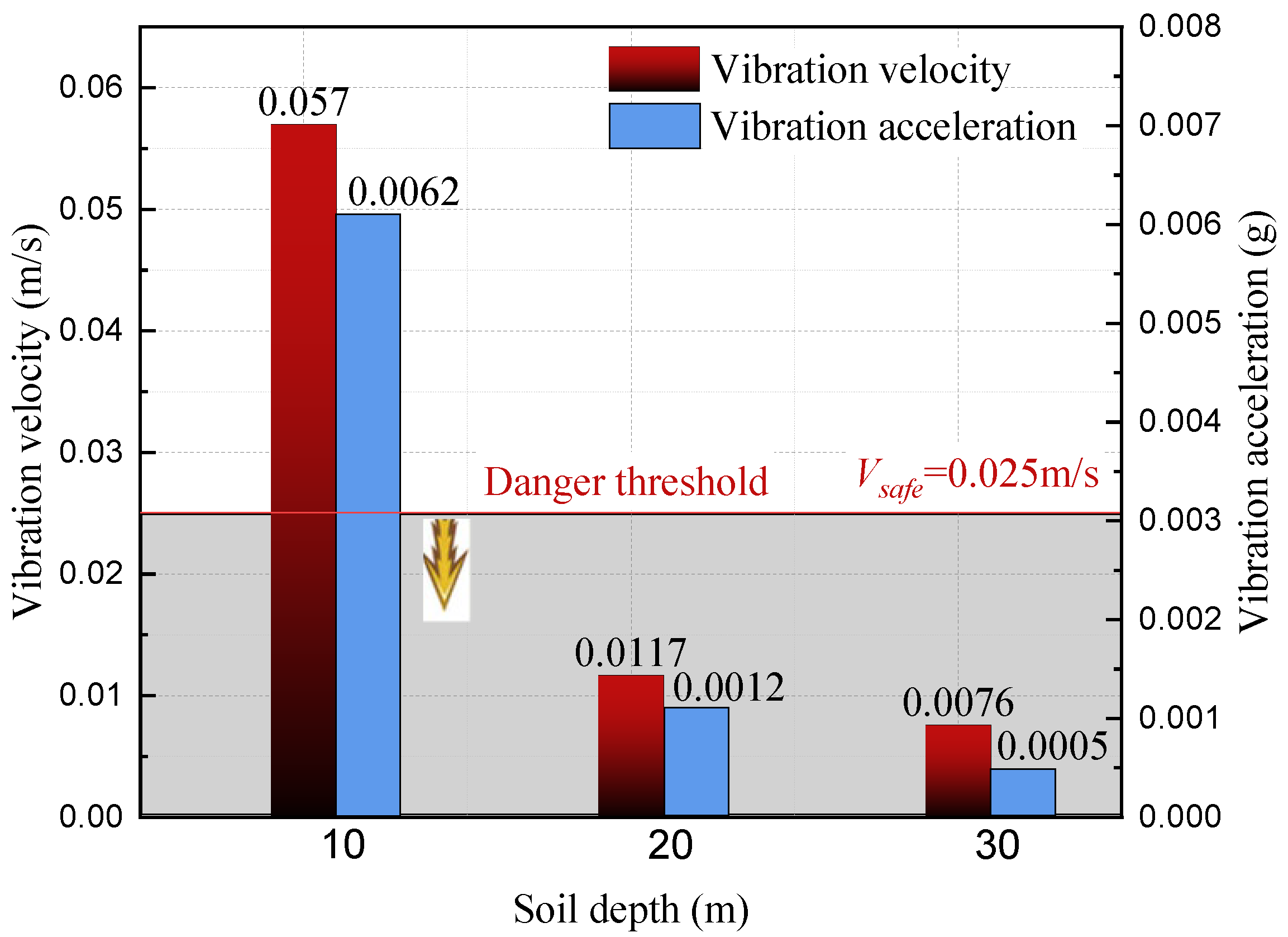
Figure 9. The tunnel was situated deep within the underground soil, featuring an inner diameter of 3.25 m and a wall thickness of 0.2 m. The explosion source was represented by TNT positioned at the center of the tunnel. Considering the geological layers, three distinct types of soil layers were identified within the tunnel from top to bottom, namely fine sand, gravel sand, and gneiss. The fine sand layer was buried at a depth of 5.60 m, while the gravel sand layer was located at a depth of 2.6 m. To investigate the impact of varying tunnel soil depths on the explosion response of ground buildings, the gneiss layers were positioned at depths of 1.8 m, 11.8 m, and 21.8 m, respectively. Consequently, the total depths of the three soil layers amount to 10 m, 20 m, and 30 m, respectively.
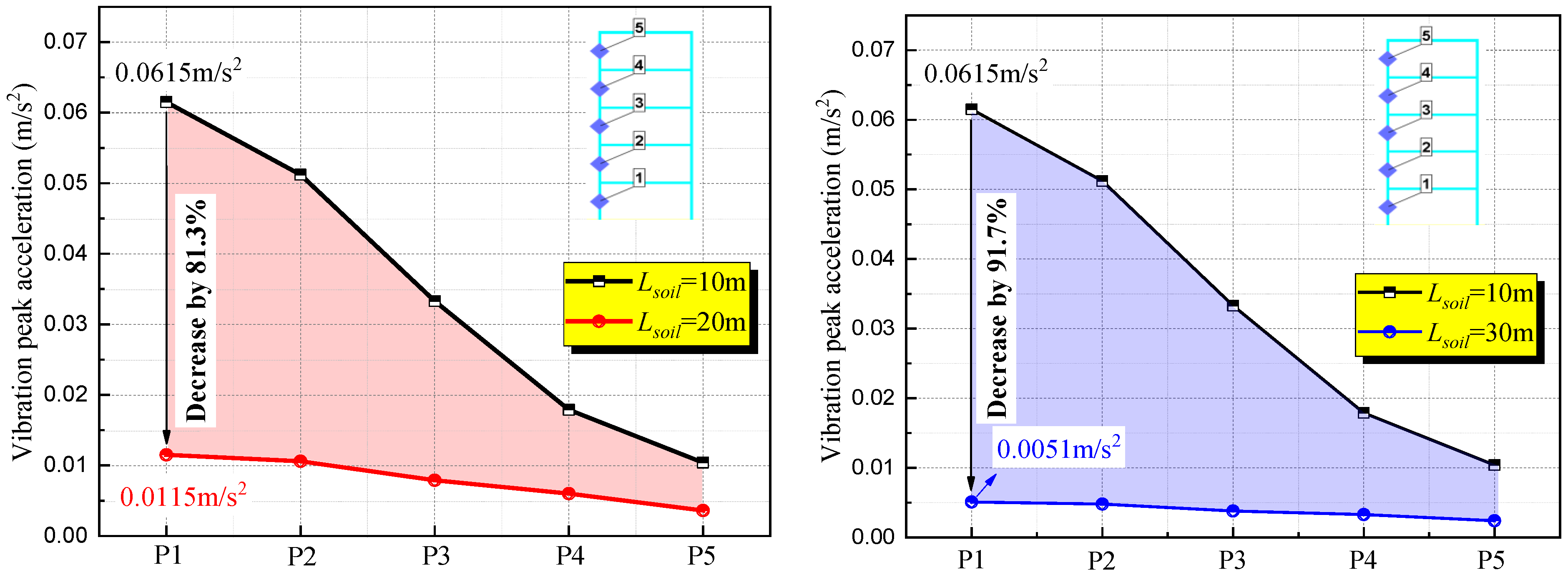
According to the prevalent pipeline laying scenario, the ground building was simplified into a five-story frame structure. The total height of the building was 15 m, with each floor being 3 m high. The width of the building frame was 0.2 m. The foundation was buried in fine sand at a depth of 5 m. To monitor the vibration response at different positions of the building structure, a monitoring point was established at the vertical center of each floor of the building. Due to the large scale of the building, modeling and calculating the three-dimensional scene would significantly reduce efficiency. As the three-dimensional building was symmetrical, a two-dimensional model could better represent the response data on the building wall without compromising calculation accuracy. To enhance simulation efficiency, a two-dimensional calculation model was chosen for this simulation.
4.1.2. Material Model
In the finite element simulation, the material model was replaced by the ideal gas state equation, and the calculation relationship between pressure and energy used was
where
P is the air pressure, with a value of 101.332 kPa;
k is the air adiabatic index, with a value of 1.4;
ρ is the air density, with a value of 1.229 × 10
−3 kg/m
3;
E is the internal energy of air, which was set to 2.068 × 10
5 mJ/mm
3.
The high-energy combustion model is often used in engineering. The initiation time of each point can be determined according to the distance between each point on the explosive and the initiation point and the detonation velocity of the explosive. The product pressure was calculated according to the following JWL state equation:
where
P is pressure,
e is the internal energy of the explosive, and the material constants
C1,
C2,
R1,
R2 and
ω are as follows:
C1 = 3.7377 × 10
5 MPa,
C2 = 3.7471 × 10
3 MPa,
r1 = 4.15,
r2 = 0.9, and
ω = 0.35.
The building model did not account for the microscopic variations in cement, masonry, and steel, treating them as a homogeneous entity. The building was modeled using the ordinary concrete material model from the material library. The state equation was set as Porous, the strength model as Drucker-Prage, and the failure model as Hydro (Pmin). The tunnel material was high-strength concrete, with the state equation set as Palpha, and the strength and failure models as RHT Concrete.
The soil in the finite element model was represented using the SAND material model, which simplified the model and considered the yield limit only in relation to pressure. The pressure-volume strain curve was utilized to depict the stress–deformation relationship of the soil under explosion loads. Soil, being a natural geological material, exhibits high anisotropy, heterogeneity, discontinuity, and randomness in its composition and structure. It also demonstrates strong nonlinearity, inelasticity, and viscosity in its mechanical properties. The stress–strain relationship is intricate and closely linked to the stress path, state, composition, structure, temperature, and environmental conditions of the soil. To accurately capture the real properties of soil, a suitable constitutive model must be employed. Given the similar characteristics of fine sand and gravel sand, the SAND constitutive model in the software was utilized. The primary mineral in gneiss is quartz sand, leading to the selection of the quartz sand constitutive model (QUARTZ constitutive model) in AUTODYN.
In 2001, Lin and Laine et al. [
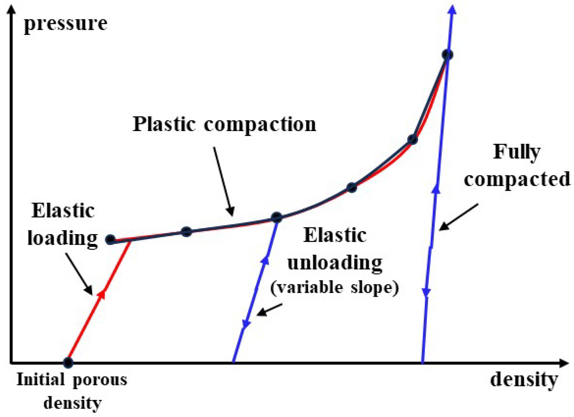
33] introduced a SAND constitutive model to characterize the mechanical behavior of sand under dynamic loading conditions. The model is grounded in Granular material model theory and integrates a series of mechanical test outcomes from sand samples to establish the specific form of the model and its associated parameters. The SAND constitutive model has been incorporated into the material database of the AUTODYN numerical calculation software. This model comprises two primary components: the linear compaction state equation and the particle strength model. The linear compaction state equation delineates the plastic compaction progression of the material through a piecewise linear function correlating pressure and density, as illustrated in
Figure 10. Additionally, a piecewise linear function linking sound velocity and density is employed to depict the elastic loading and unloading process of the material.
The particle strength model extends the Drucker-Prager strength model and encompasses the strength characteristics of granular media such as powder, clay, and sand. In addition to accounting for the pressure-induced strengthening effect, this model also incorporates the impact of density on strength and establishes a functional relationship between shear modulus and density. The particle strength model posits that the yield stress comprises two components: the influence of density and pressure variations on strength. The expression for this relationship is as follows:
where
σY is the total yield stress,
σp is the yield stress caused by the change of pressure, and
σρ is the yield stress caused by the change of density. The yield stress is expressed by piecewise linear functions of stress-pressure and stress-density.
4.1.3. Boundary Condition Setting
In the finite element model, TNT, air, and soil were represented using the Euler grid, while buildings and foundations were modeled using the Lagrange grid. The coupling between the two grids was achieved through the Constrained Lagrange in Solid algorithm. Buildings and foundations were connected to the soil and air media. To prevent reflections, the ‘flow out’ condition was defined on the boundary surface. At the initial moment, all objects had zero initial velocity and no initial force. Artificial viscosity was introduced to capture shock waves, and the second-order accuracy central difference method was employed for time advancement. The load was simulated using the LBE method, which accounted for the reflection of near-surface explosion waves. When analyzing the dynamic interaction between structures with significant rigidity and the soil layer, it may be necessary to consider phenomena like slip, detachment, and closure at the soil-structure contact surface. In this study, the surface-to-surface contact method was utilized to address the issue of mismatched foundation rigidity and soil deformation.
In the context of soil-structure dynamic interaction analysis, the research object typically involved a semi-infinite space, since vibrations or waves need to propagate to infinity. However, finite element calculations can only be performed within a bounded domain. Therefore, it became necessary to approximate the calculation boundary and utilize artificial boundaries to define the analysis area. The general principle was that the farther the distance from the underground structure, the less reflection of the wave occurs at the side boundary, resulting in a smaller impact of the artificial boundary on the dynamic response of the underground structure. To minimize the influence of reflected waves on the boundary, a common empirical practice in finite element modeling is to set the lateral boundary position at a distance of 5 to 10 times the width of the underground structure as the calculation area.
4.2. TNT Equivalent Calculation
In the context of simulating explosion loads on building structures, accurately applying the explosion load is pivotal for predicting the structural response precisely. However, there can be challenges when attempting to directly apply pressure load curves obtained from AutoReaGas to AUTODYN. To address this issue, a common approach is to use the TNT equivalent method, where all the explosion energy is converted to an equivalent TNT value for finite element simulation. In the specific case of simulating a natural gas explosion inside a 16,000 m long tunnel, simply converting all the explosion energy to a TNT value may result in an unrealistically high value, leading to inaccurate impact response predictions for ground building structures. To overcome this limitation, this paper adopted a more refined approach. Utilizing the maximum natural gas explosion pressure derived from prior simulations (2.16 MPa at the tunnel wall), this study employed explosion shock wave attenuation equations and proportional distance formulas to ascertain the TNT value that would yield a comparable explosion overpressure close to the inner wall of the tunnel at a designated distance. This methodology allows for the accurate application of the peak pressure of the natural gas explosion in the finite element simulation, providing a more realistic representation of the structural response to the explosion load.
The prediction of explosion shock wave overpressure is a topic that has been extensively studied by numerous researchers, with various models proposed for this purpose. Some of the typical models include the Mills equation, the Henrych equation, the Sadovskyi equation, and the Aliansov equation, among others. In a study conducted by Hu et al. [
34], the accuracy of prediction resulted from each model was comprehensively compared by calculating the average overpressure predicted by each model and plotting the relationship between explosion shock wave overpressure and proportional distance. It was observed that while the calculation resulting from each model exhibited the same trend of pressure decreasing with increasing proportional distance, the deviation among the models decreased gradually. The maximum relative difference between the calculated results of each model ranged between 10.3% and 11.3%. The study found that the deviation between the overpressure calculated by the Mills equation and the average value was the smallest, with a maximum relative difference of only 6%. Consequently, the Mills equation was deemed more reliable for predicting overpressure results. Based on this analysis, the present paper utilized the Mills equation for TNT equivalent calculations, as shown in Formula (11). Additionally, the proportional distance was introduced in Formula (12) to account for the influences of the TNT equivalent and for distance. Once the TNT equivalent value of the fuel was determined, the overpressure at a specific position could be calculated using the overpressure criterion
where Δ
P is the air shock wave overpressure, at 10
6 Pa, and
where
is the proportional distance
(m∙kg
−1/3),
MTNT is the TNT equivalent value of combustible gas (kg), and
R is the distance from the observation point to the explosion center (m).
In the calculation, the maximum explosion overpressure of natural gas (2.16 MPa) simulated by AutoReaGas was taken as the maximum pressure on the tunnel wall, which was ΔP in Formula (13), and the proportional distance value was 0.934. In the calculation, R was the tunnel radius of 3.25 m, and the M was calculated based on the Mills theoretical equation. Finally, the TNT value of the explosion source in the finite element simulation was about 1.52 kg. Therefore, in AUTODYN, the TNT explosion source mass in the tunnel was 1.52 kg, and the TNT was modeled using the Parts-Fill function.
4.3. Grid Independence and Simulation Model Verification
The grid independence test holds the utmost importance in constructing numerical models, as the quality of meshing directly impacts the accuracy of numerical simulation results. A common practice for grid verification involves comparing numerical calculation results using three different grid sizes: small, medium, and large. To enhance calculation efficiency while ensuring that the relative error of the explosion peak pressure does not exceed 10%, a larger grid size is selected for numerical calculation [
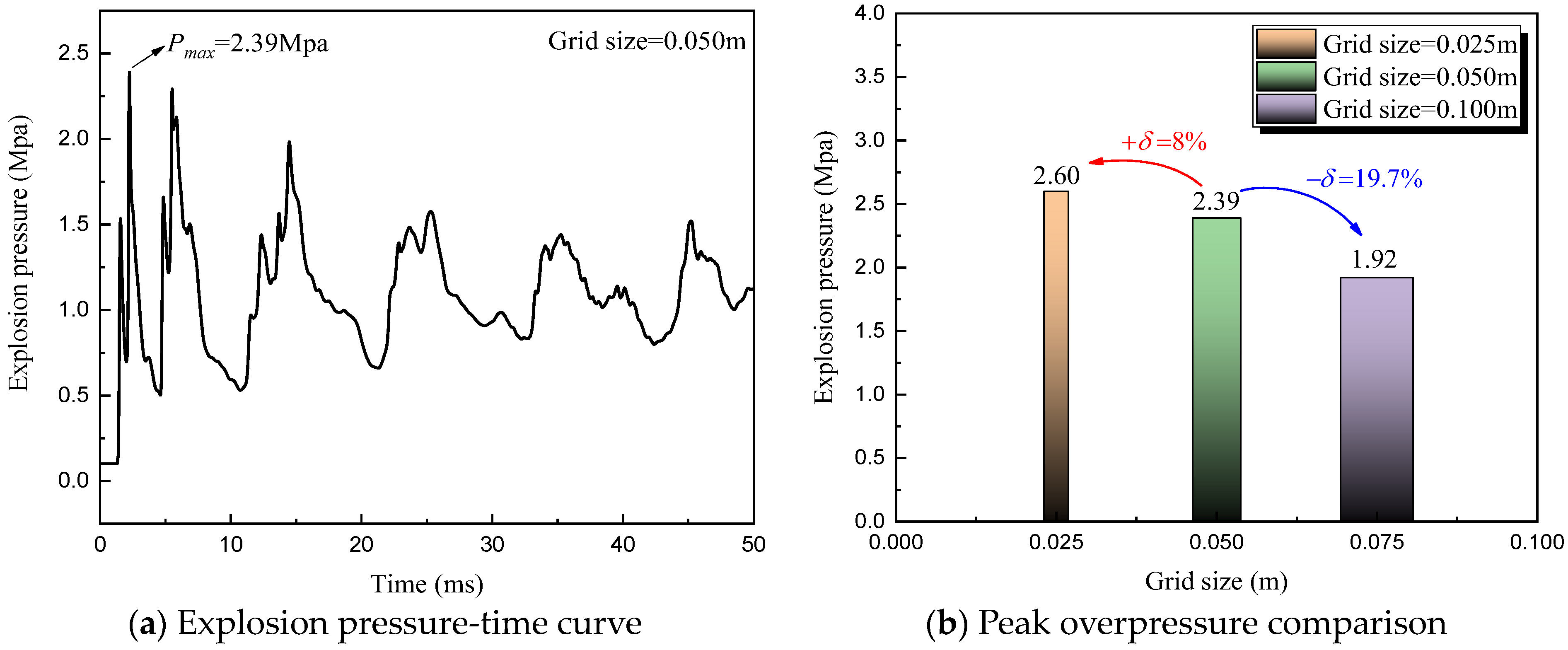
35]. In this study, grid sizes of 0.025 m (small), 0.050 m (medium), and 0.100 m (large) were used to partition the finite element calculation domain. The comparison of explosion peak pressure near the inner wall of the tunnel is illustrated in
Figure 11. The figure shows that due to multiple reflections of the explosion wave within the tunnel structure, multiple pressure peaks were observed, with the first peak being the most significant. Subsequent peaks gradually decreased with decreasing explosion energy. As shown in
Figure 11b, the relative error (
δ) of the simulated peak overpressure under the grid sizes of 0.025 m and 0.050 m was 8%, which fell within the acceptable error range. The pressure error obtained with the 0.100 m grid size exceeded 10%, indicating poor simulation accuracy compared to the other two grid sizes. To enhance simulation efficiency and achieve more accurate results, this study opted for the 0.050 m grid size for numerical calculations.
Figure 11 shows that the simulated explosion pressure peak is 2.39 MPa, while the maximum natural gas explosion pressure inside the tunnel obtained in
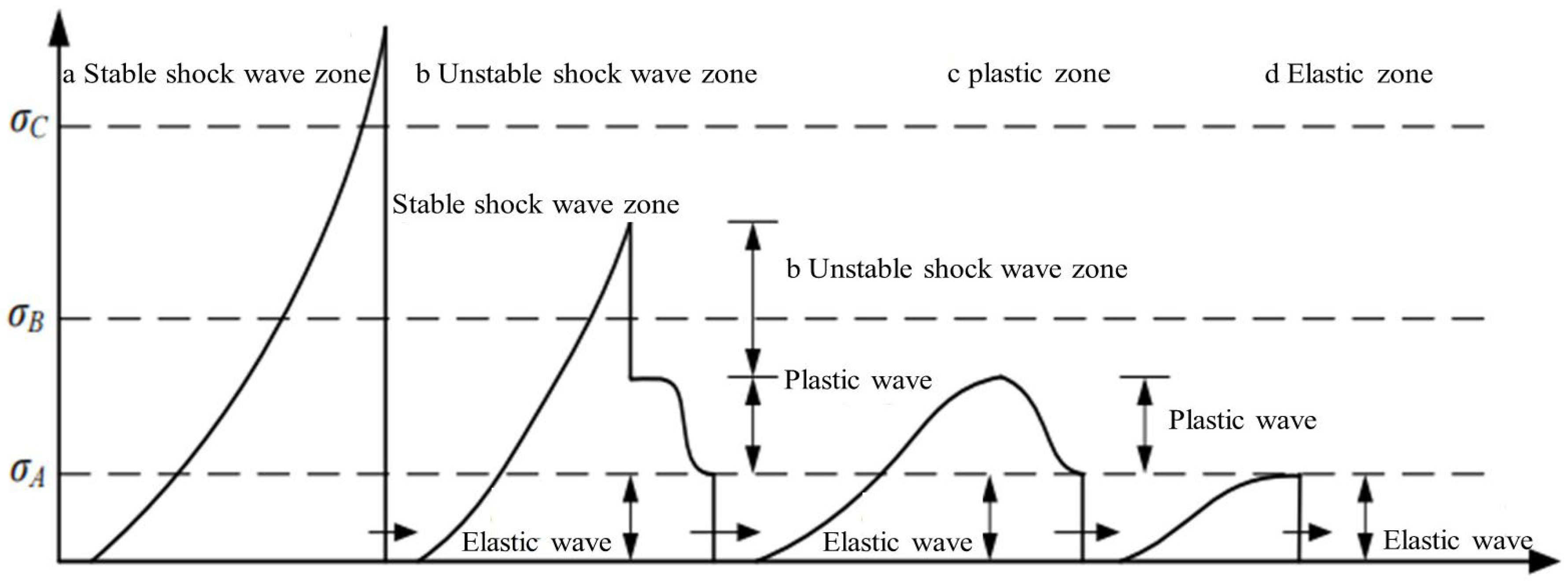
Section 4.2 is 2.16 MPa. A comparison revealed an absolute error of 0.23 MPa, with a relative error of 9.6%. This discrepancy was mainly due to the theoretical calculation formula, which often led to an inflated TNT calculation value because of simplified calculation conditions. Consequently, AUTODYN simulated a larger shock wave overpressure [
36]. In conclusion, utilizing the overpressure prediction equation ensured that the relative error of the explosion pressure simulated by AUTODYN and AutoReaGas remains within 10%, thereby verifying the accuracy of the finite element simulation model.
