Article

Impact of Jet Fires on Steel Structures: Application of Passive Fire Protection Materials

1
Higher School of Industrial, Civil and Road Engineering, Peter the Great St. Petersburg Polytechnic University, 195251 Saint-Petersburg, Russia
2
Department of Integrated Safety in Civil Engineering, Moscow State University of Civil Engineering, Yaroslav Shosse, 26, 129337 Moscow, Russia
3
State Institute of Technology (Technical University), Moskovsky Av. 24-26/49, 190013 Saint-Petersburg, Russia
*
Authors to whom correspondence should be addressed.
Fire 2024, 7(8), 281; https://doi.org/10.3390/fire7080281
Submission received: 25 June 2024 / Revised: 24 July 2024 / Accepted: 6 August 2024 / Published: 9 August 2024

Abstract

:
Jet fires are the second most common fire scenario after spill fires. This type of fire is characteristic of gas and gas–oil fires occurring on oil platforms and gas production and processing plants. The consequences of such fires are characterized by high material damage; this is associated with extensive networks of technological communications, since there is a high density of technological facilities and installations in the territory where these fires occur. At such facilities, there is a large number of steel structures, which under the action of high temperature quickly lose their strength and deform. To protect steel structures in the oil and gas industry, fire protection is used, which consists of different types: boards in the form of flat plates, plasters, and epoxy paints. This paper compares three types of fire protection materials for steel structures under jet fire: board fireproofing, plaster composition, and epoxy coating. When comparing the efficiency in jet fire, cement boards were found to be the best. However, despite the better fire protection efficiency, their low application is expected due to their massiveness and the high cost of such protection and the difficulty of installation. Nevertheless, the development of fire depends on the place of its origin, the size of the initial fire zone, and the stability and massiveness of the metal elements of the vessel structure or the structure of the boards on which the equipment can be placed. Therefore, it is necessary to take these factors into account when selecting fire protection and to apply it depending on the required fire resistance limits of structures, which should be determined depending on the fire development scenarios.

1. Introduction

Among all relevant accidents (spill, fire, flame burning), the worst-case scenario is jet fire caused by accidental leakage from pipelines [1,2,3] as well as from high-pressure gas tanks, events that recurrently arise in the assessment of fire safety risks in the oil and gas industry [4]. Jet fires are turbulent diffusion flames resulting from the combustion of a prolonged pressurized fuel release, with a significantly higher burning rate due to the turbulence of fuel and air mixing.
Experts around the world are studying the risk of fires following leaks from high-pressure pipelines of flammable gasses such as pure hydrogen, natural gas mixed with hydrogen, and natural gas containing mostly methane [5]. Natural gas jet fires caused by the ignition of blowdown pipes can cause severe structural damage and high casualties on offshore platforms [6,7].
The greatest impact is caused by horizontal jet fire, in which the peak temperature of the pipeline increases by almost twice as much as that of vertical jet fire. When there are multiple sources of jet fire, the flame intensity and coverage area increase dramatically, and the peak temperature reaches 800 °C, which leads to the destruction of the strength of pipeline steel structures [8].
The requirements of the regulatory documents of different countries and industry standards (Norwegian, French, American, and others) of major oil and gas companies and gas companies and associations prescribe to test the metal structures of equipment and technological installations and trestles where liquefied natural gas (LNG) is handled and stored in hydrocarbon fire and jet fire regimes [9,10,11,12,13]. Fire regimes differ from each other; thus, for civil objects (public and residential buildings), the standard (cellulose) fire regime is used when calculating the fire resistance of structures, whereas for industrial objects that have the possibility of hydrocarbon combustion, hydrocarbon regimes are used [14,15,16]. Figure 1 shows the curves of different fire regimes as a function of temperature and power. The hydrocarbon regime can also be of different types—jet fires [10,17], pool fires [18], and explosive burning [19]. Unprotected steel structures in such fires lose stability in 2–5 min [11,14].
Various thermal insulation materials are used to protect the integrity of the steel structure and thermal insulation in the temperature range of −200 °C to 1300 °C, which protects the steel structures of facilities, especially those producing LNG, not only from fire but also from cryogenic spills due to fire [17,20]. The materials used for such purposes are the following: basalt fiber, plaster compounds [14], intumescent compounds [21,22], and board materials [23].
There is not enough research on jet fire experiments on structures with fire-retardant coatings; manufacturers do not indicate in their descriptions the specific thickness and consumption of the material, so it is difficult to determine the competitive advantages of the materials. For example, in the work of [24], inorganic plaster formulations and organic (epoxy materials) tested in jet fire mode were considered. The indicators of the fire protection efficiency of a steel specimen at reaching the critical temperature of 648 °C amounted to 68 min for plaster composition and 9 min for epoxy paint with the thickness of compositions of 22 mm. Reference [25] reported that composites with short fibers between woven layers reduced the linear burning rate by up to 18.7% and were able to achieve low flame spread rates comparable to chopped fiber samples.
Test methods governing the effect of jet combustion (including after cryogenic filling) on the fire protection coating of a steel structure are set out in a number of standards [26,27,28]. ISO 22899:1 does not regulate the test time and critical temperature (according to [26], the critical temperature is the temperature at which the yield strength of steel is reduced to the minimum allowable strength under service loads). The critical temperature is determined by the designer and is dependent on the material of the protected structure and the requirements of various regulatory factors, including industry documents [13]. The critical temperature depends on loads, cross-sections, loading conditions, etc. For example, the critical temperature for supporting structures of offshore platforms is 400 °C [29], 538 °C according to UL 1709 [10], 550 °C according to GB 14907 [30], and 500 °C according to GOST R 53295 [31].
The websites of manufacturers of fire retardants certified using this method [26] do not specify the critical temperature, material consumption, and test time. Only the fact that jet burning tests have been performed is indicated. The test time also varies and is indicated in the advertising descriptions of coatings: 0.5–3.0 h.
The thickness of certified fire-retardant coatings tested for jet fire mode such as CharCoat JF is 3–40 mm depending on the design requirements [32]; Chartek 7 and Chartek coatings are 8–6 mm for a fire resistance of 41 and 15 min respectively [33], while Jotachar JR coatings are 2–35 mm [34].
According to [35], Chartek 1709 provides not only hydrocarbon combustion but also jet combustion. For hydrocarbon combustion, a fire resistance of 60 min is achieved with a coating thickness of 5.12 mm without mesh. With the mesh, the values are as follows: fire resistance 1.5 h at a coating thickness of 7.85 mm; 2 h at 10.57 mm; 3 h at 15.21 mm; 3.5 h at 15.21 mm; and 4 h at 18.99 mm. Considering that the jet fire curve is much higher on the graph (Figure 1), an increase in coating flow rate of 15–20% can be predicted compared to the H-mode experiments. Thus, a comparative analysis of tested fire protection systems is difficult. It is relevant to establish certain experimental data for fire protection products when exposed to jet fire modes.
The paper presents the new results of experimental studies on the impact of jet fire modes on metal structures with fire protection made of three common materials in the oil and gas industry: cement particle boards, vermiculite plaster, and epoxy intumescent paints. The comparative analysis of these fire protection means is carried out, and on the basis of the new results and literature data, nomograms of temperature–time dependences and material consumption for gypsum compositions and epoxy intumescent paints are constructed.

2. Materials and Methods

2.1. Methods

Experimental studies of passive fire protection systems for resistance to jet fires are conducted according to ISO 22899-1 [26]. The individual thermal and mechanical loads defined in this document, which act on the material in a jet fire, are similar to those that occur in large-scale jet fires caused by high-pressure releases of natural gas.
The essence of the method for evaluating the protective properties of the material under test is to determine whether the test specimen reaches the time and/or temperature limit when exposed to the jet combustion (reactive flame) of propane. Since the ISO 22899:1 [26] allows the customer of the test to set the limit time and temperature, after the achievement of which the test is completed, in the article for comparative analysis we will take the limit value of time and temperature equal to 60 min and 500 °C, respectively.
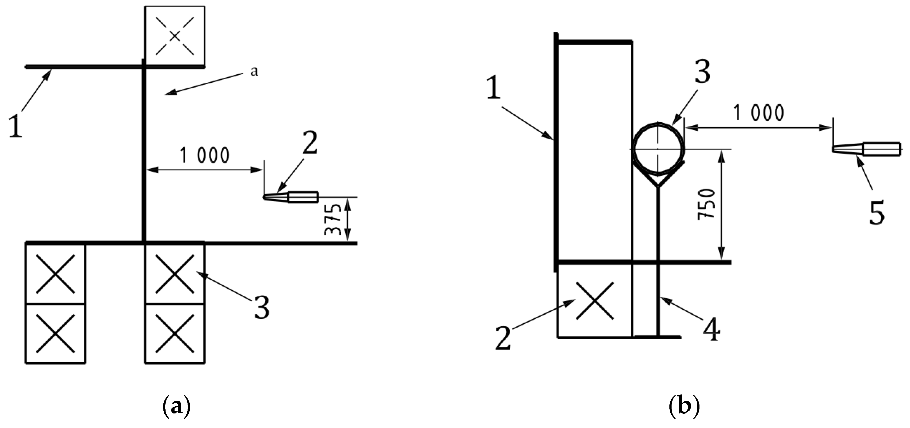
ISO 22899-1 [26] provides two basic test configurations. The first configuration is internal, where one or more internal surfaces of the flame recirculation chamber are incorporated into the test structure (Figure 2a). The second configuration is the external configuration, with the test structure mounted on supports in front of the flame recirculation chamber (Figure 2b). The fuel nozzle is placed at a distance of 1000 ± 50 mm from the surface of the specimen opposite its geometric center, and its height depends on the configuration (external configuration—750 mm, internal configuration—375 mm).
The key elements of the test are the jet exit nozzle, the flame recirculation chamber, and the containment chamber. All elements are required for the internal test configuration, and the test specimen is all or part of the flame recirculation chamber. In external test configurations, the flame recirculation chamber is used only to create the fireball, and it is not necessary to use the containment chamber.
The flame recirculation chamber is a mild steel box that is open at the front, into which a flame jet is directed to form a recirculating flame, resulting in a fireball. In terms of the protective chamber, this can be understood as a mild steel box, open at the front and rear, which is designed to be attached to the rear of the flame recirculation chamber for the purpose of protecting the rear from environmental influences.
The cone-shaped tapered nozzle used for the tests is made of heat-resistant stainless steel and has a length of (200 ± 1.0) mm, an inner diameter of (17.8 ± 0.2) mm, and an outer diameter of (33.8 ± 0.2) mm. The nozzle is fed with fuel through a (52 ± 0.5) mm diameter stainless steel pipe. The scheme of the nozzle is shown in Figure 3.

2.2. Materials

The paper will discuss jet combustion resistance testing of 4 types of passive fireproofing (2 types of fire protection paints, structural fire protection, and fire protection plaster).

2.2.1. Structural Fire Protection

Sample No.1. Structural fire protection is a protective coating system (Figure 4) mounted on I-beam 20B1 [36]: (a) the fire protection layer is 25 mm thick “IGNIS-mat SV” on the basis of silica fiber [37]; (b) the fire barrier is made of superfine basalt fiber “Promizol-Proplate” [38]; (c) the fire protection layer is “IGNIS-mat SV” with a layer thickness of 25 mm; (d) the two layers of fire protection boards on the cement binder are both a “PROZASK Firepanel” of 25 mm each [39].
The characteristics of non-combustible flame retardant mat “IGNIS-mat CB” are presented in Table 1.
The fireproof barrier “PROMIZOL-Proplat” is a product of fireproof non-combustible material based on flame retardant flint fabric and superfine basalt fiber. It is used for the fireproof sealing of seams and joints of various configurations, operating under conditions of alternating deformation, as well as for the manufacture of enclosing structures and flexible and rigid closed channels of building structures. It retains its elastic properties through the destruction of the outer coating and internal structure under a compression up to 60%, a tension up to 40% and shear up to 30% of the designed width of the joint [38].
«PROZASK Firepanel» fire protection boards [39], the characteristics of which are given in Table 2, consist of Portland cement and light mineral aggregate, reinforced on both sides with glass mesh and coated on the front side with impregnation varnish to increase protective properties.
The specimen is tested using the external configuration. The scheme of installation of the fireproofing system based on fireproof boards “PROZASK Firepanel” is given and the installation of the temperature sensors is shown in Figure 5.

2.2.2. Fire Protection Coatings (FPC)

Fire-retardant paints (from which coatings are formed) are a two-component system consisting of a base and a hardener. The base is a suspension of foam-forming fillers, pigments, and functional additives in a solution of epoxy resin and a mixture of organic solvents (hardener-aliphatic polyamine resin). Characteristic coatings are given in [40]. Table 3 summarizes the physical and technical characteristics of epoxy coatings.
To prepare the composition, the base is mixed to a homogeneous state and hardener is added (ratio of base and hardener by mass 3.5:1); after mixing, the composition is ready for use. The conditions of the application of the composition range in temperature from −5 to +40 °C, with a relative air humidity at no more than 80%. Further we consider the tests of fire-retardant-foaming coatings, FPC-1 and FPC-2, of two different manufacturers, the characteristics of which are similar and do not differ significantly, according to Table 3.
Sample No. 2. For protection against jet combustion, the fire-retardant epoxy composition FPC-1 is applied to the sample, which consists of a square shape made of carbon steel with a thickness of 10 mm and with internal dimensions of 1500 × 1500 × 500 mm, with the central shelf made of carbon steel with a thickness of 20 mm, a depth of 250 mm, and an actual thickness of the dry layer at 10.89 mm. This sample was then investigated, with the test of specimen No. 2 carried out according to the internal configuration.
Sample No. 3. The fire protection coating FPC-2, applied on the square shape sample made of carbon steel with a thickness of 10 mm and internal dimensions of 1500 × 500 mm, with a central shelf made of carbon steel with a thickness of 20 mm and a depth of 250 m, was subjected to a jet combustion study. The coating was applied in 24 layers. To ensure FPC-2 stability, carbon reinforcement mesh was used, placed in 2 layers: 1 mesh (inner) between the 13 and 14 coating layers; 2 meshes (outer) between the 19 and 20 coating layers. The arithmetic mean value of the total thickness of the fireproof coating was 31.15 mm.
The tests of specimen No. 3 were carried out according to the internal configuration.
Sample No. 4. Fire protection coating FPC-2, in the form of a two-component system consisting of a base and a hardener, and applied to a steel pipe in 31 layers, was subjected to a jet combustion study. To ensure the stability of the PRP, carbon reinforcing mesh was used, placed in 2 layers: 1 mesh (inner) between the 13 and 14 coating layers; 2 meshes (outer) between the 21 and 22 coating layers.
The arithmetic mean value of the total thickness of the fireproof coating was 31.8 mm.
The tests of specimen No. 4 were carried out according to the external configuration.

2.2.3. Fireproof Plaster

Sample No. 5. The plaster composition is a non-combustible composition of a mixture of Portland cement (50–70%), vermiculite (30–60%), calcium sulfate (50–70), and mineral fiber (1–10%), with a density of 350–550 kg/m3. Depending on the thickness of the composition, the fire resistance can perform well 120 min or longer. For protection against jet combustion, a fireproofing system on a cement–vermiculite base applied to a square-shaped specimen made of carbon steel, with a thickness of 10 mm and internal dimensions of 1500 × 500 mm, with a central shelf made of carbon steel with a thickness of 20 mm and a depth of 250 mm, was investigated. The fire protection coating consisted of 2 layers: firstly, 1 layer of primer coating 2 mm thick was applied; then, the fire protection coating 53.4 mm thick with reinforcing mesh was applied. The list of tested systems and test configuration are given in Table 4.

3. Results

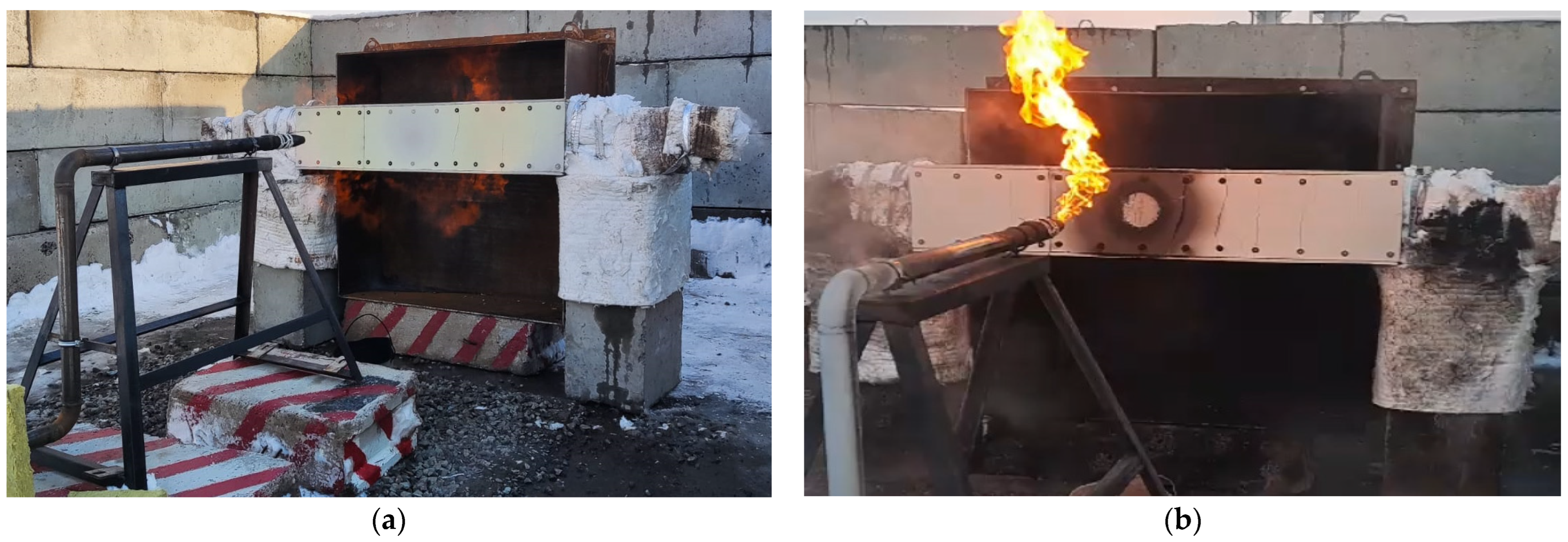
Sample No. 1. During the experiment, reaching the limit values (exposure time to the burning propane jet equal to 60 min or reaching the temperature of 500 °C according to the average values of the temperature sensors) was recorded. The specimen during the test is shown in Figure 6.
At the end of the tests, a visual inspection was carried out. There were no foci of burning on the surface, but shrinkage and significant damage to the first layer of fireproof boards was observed in the form of through burning and cracking and a color change to black on the surface of the board and fasteners where they were exposed to a jet of burning propane. The second layer of boards, fasteners, wires protected by fireproof mats, and the mats themselves were not damaged (Figure 6). It is obvious that such a system should consist of at least two 25 mm thick «PROZASK Firepanel» boards.
In the mode of exposure to burning gaseous propane (jet fire mode), the system consisting of two layers of fireproof mats “IG-NIS-mat SV” 25 mm thick each, the fire barrier “PROMIZOL-DSH PROPLATE-60/5/10L”, and two layers of fireproof boards “PROZASK Firepanel”, installed on the I-beam 20B1, provides the maximum average temperature on the sample at 47.73 °C within 60 min.
Sample No. 2. The average temperature on the unheated side of the steel structure to which the fire-retardant epoxy composition FPC-1 with the actual dry layer thickness of 10.89 mm was applied, in the mode of exposure to burning propane gas, amounted to 184.84 °C at the 60th minute of the test.
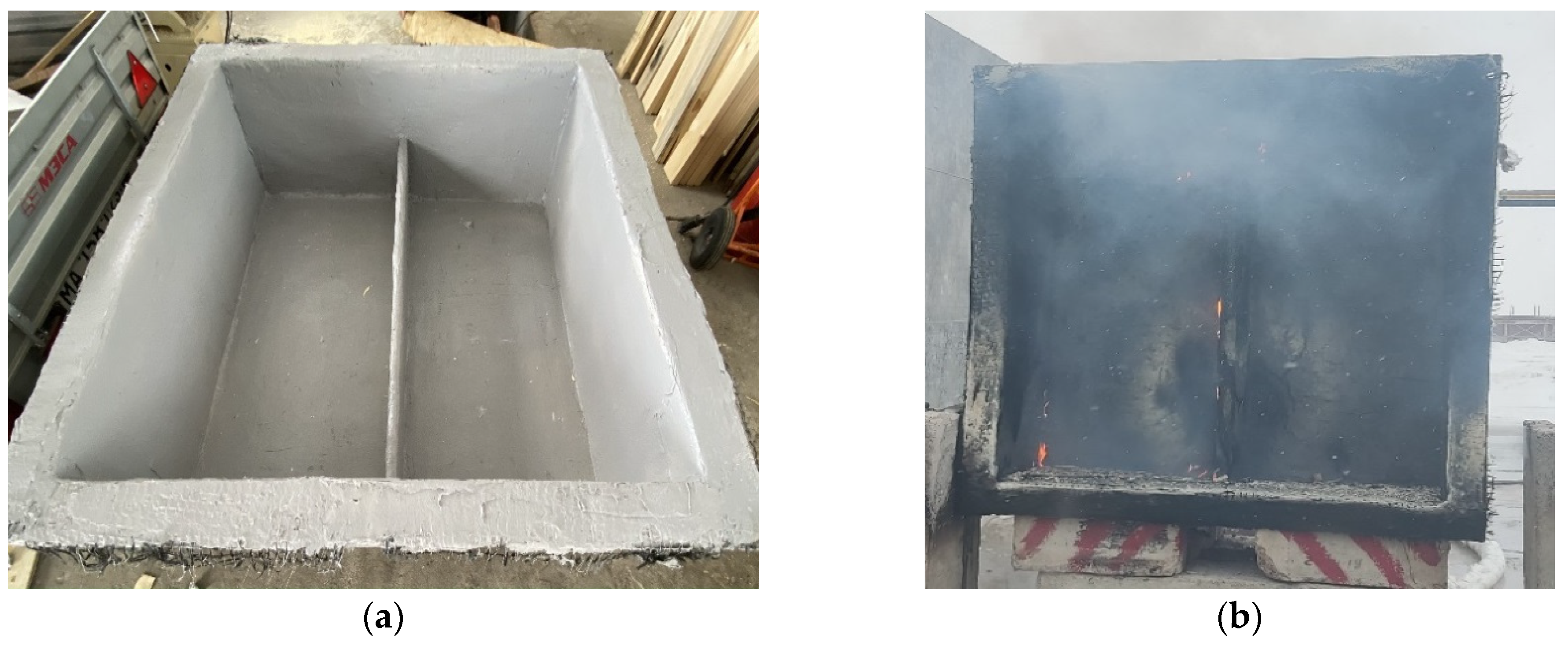
As a result of visual inspection, it was found that there were foci of combustion under the center shelf and in the upper part of the specimen. The darkening of the composition and cracks 9.91–26.37 mm deep were observed over the entire area. The coating on the specimen swelled over the entire area, while the foam coke was firmly attached to the specimen; the reinforcing mesh was not damaged. In the jet impact zone, a decrease in the thickness of the protective layer is observed. In the upper part of the specimen, on the “skirt”, the melting and leakage of the coating composition is observed (Figure 7a). Temperature sensor readings during the test are shown in Figure 7b.
Sample No. 3. The average temperature of the specimen did not exceed the limit value during 60 min and amounted to 82 °C.
The first swelling on the surface of the specimen was recorded at the 6th minute of the test; the flight of small particles of the intumescent layer was recorded at the 25th minute.
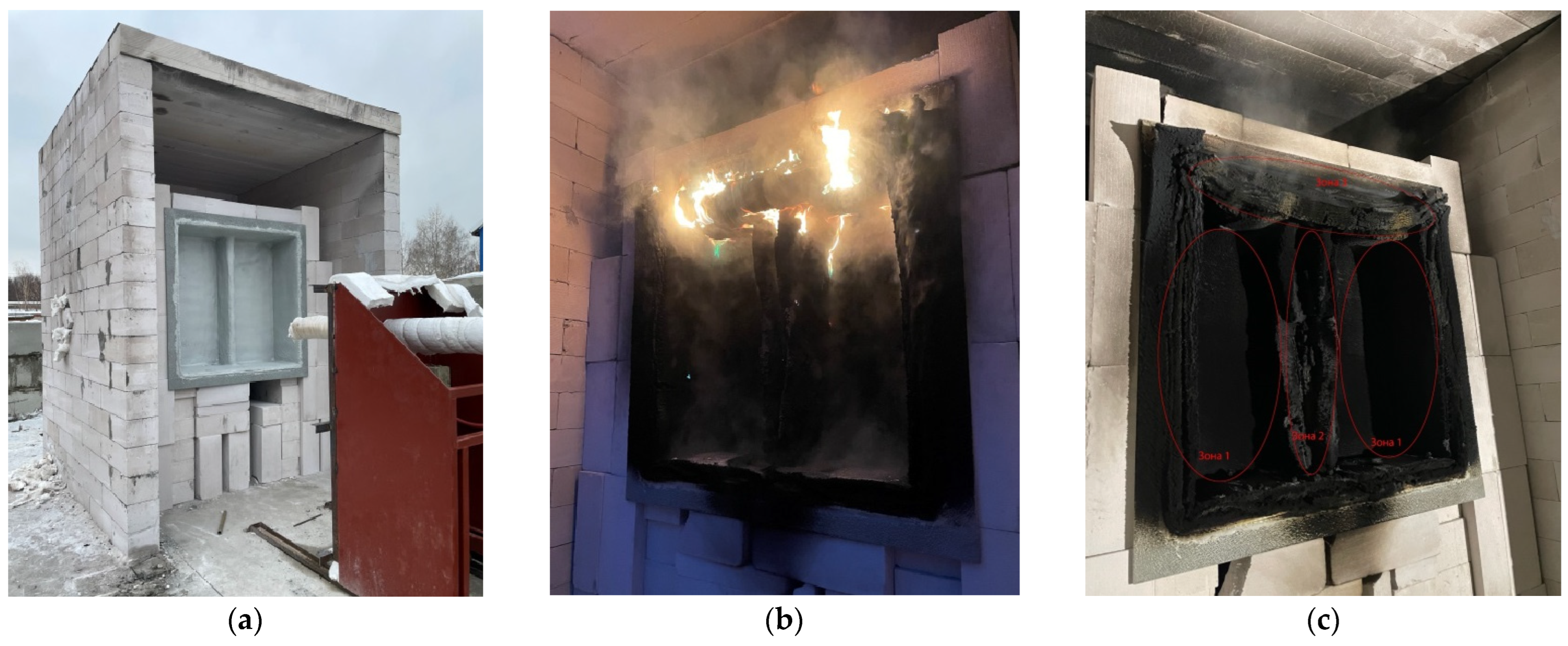
At the end of the test, a dense layer of expanded flame retardant was observed throughout the specimen. The residual burning of the specimen was observed (Figure 8c).
Visually, the specimen can be divided into three zones (indicated in Figure 8c):
-
Zone 1—reacted up to the second (outer) mesh, the flame-retardant coating is firmly in place, and the entire mesh is intact and attached;
-
Zone 2—has reacted up to the second (outer) mesh, the fireproofing is firmly in place, there is localized FPC failure, and the entire mesh is intact and anchored;
-
Zone 3—bare metal insulation, poor condition of reinforcement, and the reacted FPC is easily separated.
The thickness of the crumbling layer in zones 1 and 2 averages was 60 mm; the thickness of the dense FPC layer in zones 1 and 2 was averaged to 33 mm (indicating slight crumbling of the fireproofing without significant change in its structure under the crumbling layer); the thickness of the crumbling layer in zone 3 averaged to 140 mm.
The view of the specimen before and after the test is shown in Figure 8.
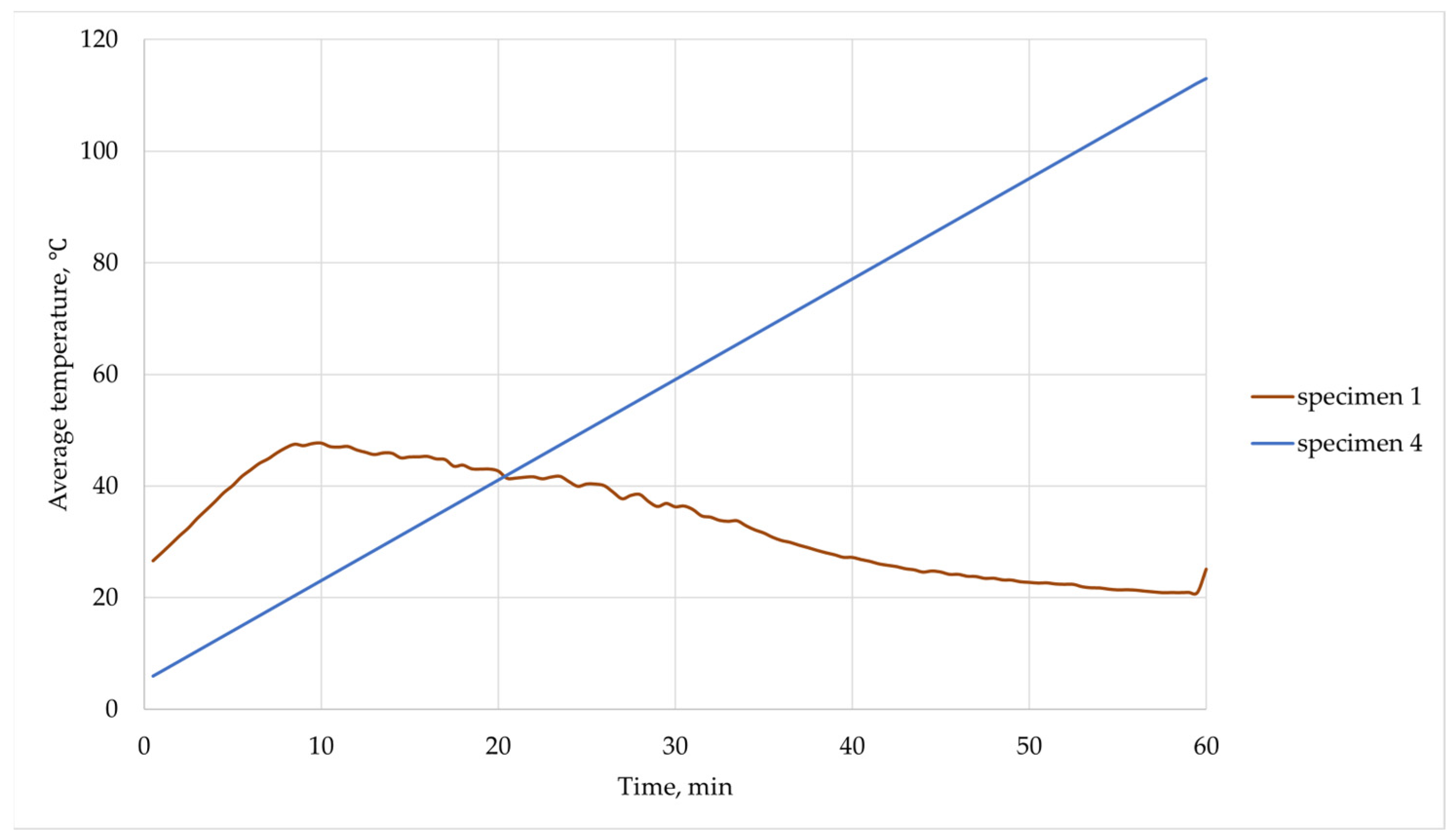
Sample No. 4. The average temperature during the test did not exceed the limit value of 60 min and amounted to 113 °C. The maximum temperature after 72 min was 132 °C, which is shown in Figure 9.
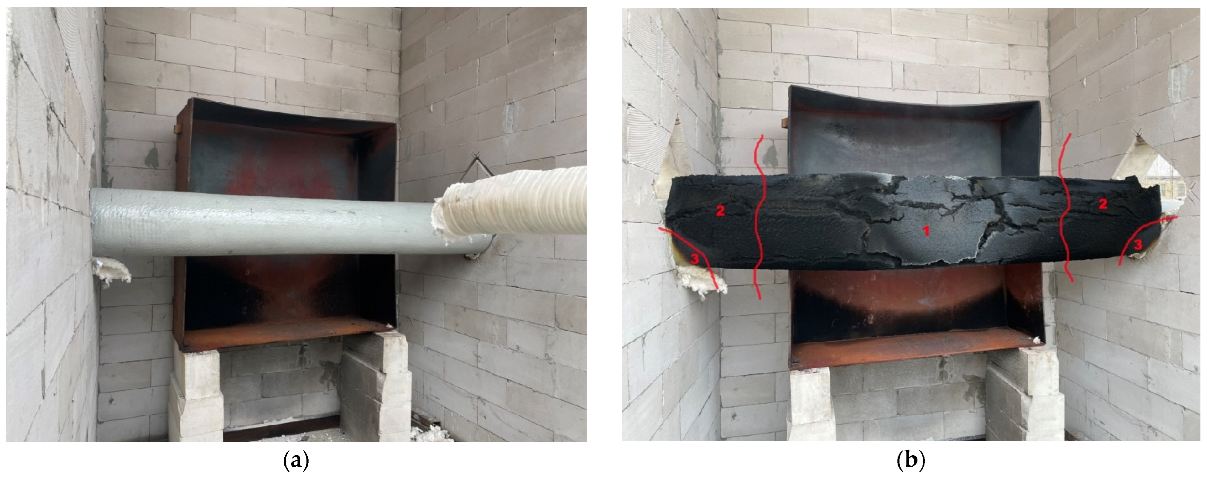
The view of the specimen before and after the test is shown in Figure 10.
The first swelling on the surface of the specimen was recorded at the 5th minute of the test; the flight of the small particles of the intumescent layer was recorded at the 30th minute.
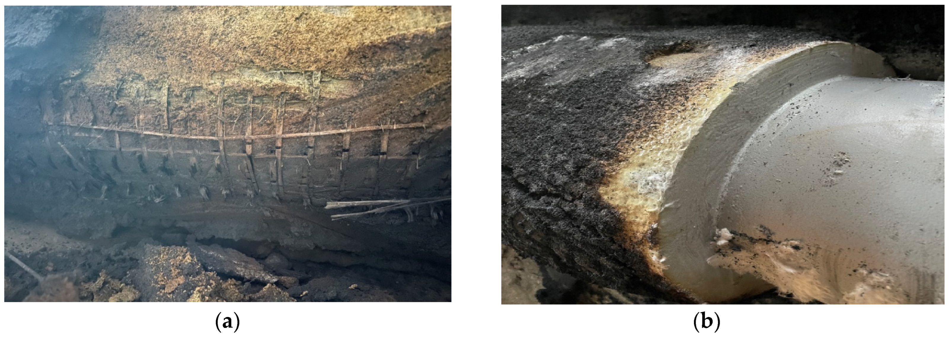
At the end of the test, a dense layer of intumescent fire retardant was observed throughout the specimen (Figure 10b). Visually, the specimen can be divided into three zones:
-
Zone 1—the flame retardant that reacted on the second (outer) mesh is firmly retained, a localized FPC failure is observed, and the entire mesh is intact and anchored;
-
Zone 2—the flame retardant that reacted on the surface is firmly retained, and the entire mesh is intact and secured;
-
Zone 3—the unreacted/partially-reacted material is present, the unreacted-material and reinforcement are firmly retained.
The thickness of the foam coke layer in zone 1 averaged 65 mm; the thickness of the FPC foam coke in zone 2 averaged 30.2 mm (indicating an insignificant amount of foam coke without significant changes in its structure under the FPC suspension layer); the thickness of FPC foam in zone 3 averaged 12 mm (see Figure 11).
Specimen No. 5. Prior to testing, there were several surface cracks on the surface of the specimen.
During the test, flames engulfed the specimen, making it difficult to see the specimen surface through the flames. Smoke was observed periodically throughout the test.
The inspection of the structure after the specimen had cooled revealed large cracks in the rear surface of the coating. A layer of charred material had formed on a significant portion of the rear surface of the passive fireproofing.
The maximum temperature of the specimen was 269.1 °C and was recorded on the unheated surface of the specimen, 250 mm to the left of the center line, after 181 min of exposure to the flame jet.
The graph of dependence of the average temperature on time (up to 60 min) of exposure to the flame jet is presented in Figure 12.

4. Discussion

For the correct analysis, we will analyze the results of the tests performed on identical configurations according to ISO 22899-1 [26]. Therefore, the test results of specimen №1 will be compared with specimen №4 (external configuration), and the test results of specimens №2, №3, and №5 (internal configuration) will be compared with each other (Table 5).
After reaching 60 min of exposure to the fire jet, the average temperature of sample No. 1, with a fireproofing system installed on it, consisting of two layers of fireproof mats and boards, was 47.73 °C, which is 2.5 times higher than the temperature of sample No. 4, which was covered with a fireproof coating, FPC-2, with a thickness of 31.8 mm (the temperature was 113 °C after 60 min of testing).
Also added to the table are data from [24] for an inorganic material (apparently plaster) and an organic material (apparently epoxy coating). The temperature on the unheated surface is also listed at 500 °C, not 648 °C.
After reaching 60 min of exposure to the fire jet, the average temperature of samples No. 2 (FPC-1), No. 3 (FPC-2), and No. 5 (fire protection system on the cement–vermiculite base-plaster FPC-1) was 184.84 °C, 113 °C, and 97 °C, which is lower than the value of the critical temperature (500 °C) by several times. The difference in the value of the average temperature of samples No. 2 and No. 3 is justified not only by the different compositions of fireproof coatings (it is assumed that the compositions are similar, but it is possible that this is not true, because the manufacturers of materials are different), but also by the different thicknesses of the application of the materials.
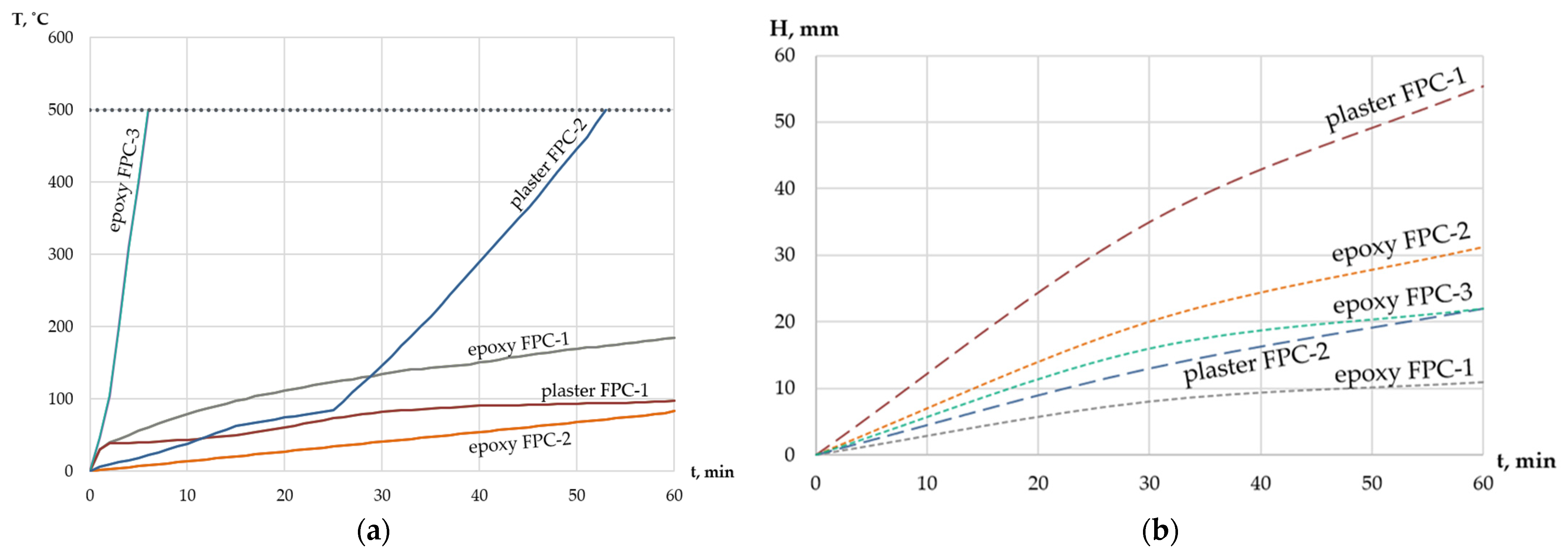
According to the results of the experiments described earlier in the text and in the article [24], the dependences of the average temperature of the steel structure and the thickness of the fireproof coating on the time of fire jet exposure were plotted (Figure 12).
Figure 12. Relationship curves for plaster and epoxy coatings: (a) time to reach critical temperature; (b) material thickness at which the critical temperature of 500C is reached within 60 min of the experiment.
Fire 07 00281 g012
The graphs reflect the properties of protective functions of only epoxy-based coatings (epoxy FPC-1,2,3) and plaster coatings (plaster FPC-1, 2) (boards are not considered due to a single experiment), and are recommended for use in the selection of fire-retardant coatings for load-bearing steel structures. As can be seen from the graph (Figure 12a), the best properties have epoxy composition FPC-2 (sample No. 3): it heats up for 60 min only to a temperature of 82 °C; the worst properties have epoxy composition FPC-3 (sample on organic material No. 6 [24]), which showed such poor results due to flame erosion when the foam coating was blown off the steel coating. In addition, reinforcing mesh was applied at intervals on specimens No. 2, No. 3, and No. 4, which was not carried out on specimen No. 6 [24]. Therefore, the result for FPC-3 should not be considered as relevant. Figure 12b shows the model curves of reaching the critical temperature of 500 °C in 60 min as a function of thickness. It is evident that plaster formulations have the greatest thickness, and the greater the thickness (55.4 mm for plaster FPC-1 and 22.0 mm for plaster FPC-2), the longer the time to reach the critical temperature (97 min and 55 min, respectively).

5. Conclusions

In this study, cement boards performed better when comparing the effectiveness of reactive fireproofing. The boards were more effective than epoxy compound. However, despite their higher fire-protection effectiveness, their application is expected to be low due to their massiveness and the high cost of such protection and their difficulty in installation. The plaster compound proved to be almost comparable to cement boards, which is understandable based on the relatedness of the chemical composition. Nevertheless, the development of fire depends on the location of its origin, the size of the initial ignition zone, and the stability and massiveness of the metal elements of the ship structure or the structure of the boards on which the equipment can be placed. Therefore, it is necessary to consider these factors when selecting fire protection and apply it depending on the required fire resistance limits of structures, which should be determined depending on the scenarios of fire development. Obviously, it is worth considering the material properties (combustible or non-combustible), performance, and cost.

Author Contributions

Conceptualization, M.G.; methodology, M.G. and D.K.; formal analysis, D.K.; investigation, M.G. and F.P.; data curation, E.N. and D.K.; supervision, M.G.; writing—original draft, E.N and S.D. All authors have read and agreed to the published version of the manuscript.

Funding

The research was funded by the National Research Moscow State University of Civil Engineering (grant for fundamental and applied scientific research, project No. 21-392/130).

Institutional Review Board Statement

Not applicable.

Informed Consent Statement

Not applicable.

Data Availability Statement

Data are contained within this article.

Acknowledgments

The authors are grateful for the help, support and materials provided by PROZASK LLC and RPC PROMIZOL LLC (Russia), the holding company of VMP JSC (Russia), GILAN MICA Ltd., United Kingdom.

Conflicts of Interest

The authors declare no conflicts of interest.

References

  1. Wang, Z.; Zhou, K.; Zhang, L.; Nie, X.; Wu, Y.; Jiang, J.; Dederichsc, A.S.; He, L. Flame extension area and temperature profile of horizontal jet fire impinging on a vertical plate. Process Saf. Environ. Protect. 2021, 147, 547–558. [Google Scholar] [CrossRef]
  2. Li, M.; Wang, Z.; Jiang, J.; Lin, W.; Ni, L.; Pan, Y.; Wang, G. Numerical Simulation and Consequence Analysis of Full-Scale Jet Fires for Pipelines Transporting Pure Hydrogen or Hydrogen Blended with Natural Gas. Fire 2024, 7, 180. [Google Scholar] [CrossRef]
  3. Karimi Dehkordi, M.; Behnam, B.; Ghasemi Pirbalouti, R. Probabilistic fire risk analysis of process pipelines. J. Loss Prev. Process Ind. 2022, 80, 104907. [Google Scholar] [CrossRef]
  4. Kashi, E.; Bahoosh, M. Jet fire assessment in complex environments using computational fluid dynamics. Braz. J. Chem. Eng. 2020, 37, 203–212. [Google Scholar] [CrossRef]
  5. Wu, Y.; Zhou, K.; Huang, M.; Zhou, M. Flame behavior of jet fire confined by the tank wall. Huagong Xuebao/CIESC J. 2021, 72, 2896–2904. [Google Scholar] [CrossRef]
  6. Xie, W.; Li, J.; Shi, J.; Zhang, X.; Usmani, A.S.; Chen, G. Probabilistic real-time natural gas jet fire consequence modeling of offshore platforms by hybrid deep learning approach. Mar. Pollut. Bull. 2023, 192, 115098. [Google Scholar] [CrossRef] [PubMed]
  7. Panaitescu, M.; Panaitescu, F.-V.; Voicu Iscupi, A.-A. FTA on ship firefighting plant. J. Mar. Technol. Environ. 2023, 42–49. [Google Scholar] [CrossRef]
  8. Zhou, N.; Wu, L.; Li, X.; Li, X.; Shi, J.; Cao, L. Experimental study on failure features of petrochemical pipelines under jet fire. China Saf. Sci. J. 2022, 32, 135–141. [Google Scholar] [CrossRef]
  9. NORSOK M-501:2022; Surface Protection and Protective Coating. NORSOK. 2022. Available online: https://www.scribd.com/document/664856568/Norsok-M-501-2022 (accessed on 7 August 2024).
  10. UL 1709–2022; Standard for Safety Rapid Rise Fire Tests of Protection Materials for Structural Steel. Underwriters Laboratories (UL): Northbook, IL, USA, 2022. Available online: https://www.normadoc.com/english/ul-1709-2022.html (accessed on 7 August 2024).
  11. API RP 2218; Fireproofing Practices in Petroleum and Petrochemical Processing Plants. API Publishing Services: Washington, DC, USA, 2013; p. 68. Available online: https://www.apiwebstore.org/standards/2218 (accessed on 7 May 2024).
  12. GS EP SAF 337; Total, S.A. «General Specification Safety. Passive Fire Protection: Basis of Design». TOTAL S.A. Available online: https://www.collegesidekick.com/study-docs/1530436 (accessed on 7 August 2024).
  13. EN 1991-1-2; Eurocode 1: Actions on Structures—Part 1–2: General Actions—Actions on Structures Exposed to Fire. CEN (European Committee for Standardization): Brussels, Belgium, 2002. Available online: https://www.phd.eng.br/wp-content/uploads/2015/12/en.1991.1.2.2002.pdf (accessed on 25 May 2024).
  14. Gravit, M.; Dmitriev, I.; Shcheglov, N.; Radaev, A. Oil and Gas Structures: Forecasting the Fire Resistance of Steel Structures with Fire Protection under Hydrocarbon Fire Conditions. Fire 2024, 7, 173. [Google Scholar] [CrossRef]
  15. Bjørge, J.S.; Metallinou, M.-M.; Kraaijeveld, A.; Log, T. Small Scale Hydrocarbon Fire Test Concept. Technologies 2017, 5, 72. [Google Scholar] [CrossRef]
  16. Put, F.; Lucherini, A.; Merci, B.; van Coile, R. Model uncertainty in a parametric fire curve approach: A stochastic correction factor for the compartment fire load density. Fire Saf. J. 2024, 144, 104113. [Google Scholar] [CrossRef]
  17. Bradley, I.; Willoughby, D.; Royle, M. A review of the applicability of the jet fire resistance test of passive fire protection materials to a range of release scenarios. Process Saf. Environ. Prot. 2019, 122, 185–191. [Google Scholar] [CrossRef]
  18. ASTM E 1529-14A; Standard Test Methods for Determining Effects of Large Hydrocarbon Pool Fires on Structural Members and Assemblies. ASTM International: West Conshohocken, PA, USA, 2014.
  19. Guidelines for Vapor Cloud Explosion, Pressure Vessel Burst, BLEVE, and Flash Fire Hazards, 2nd ed.; John Wiley & Sons, Inc.: Hoboken, NJ, USA, 2010.
  20. Mikalsen, R.F.; Glansberg, K.; Wormdahl, E.; Stølen, R. Jet fires and cryogenic spills: How to document extreme industrial incidents. In Proceedings of the Sixth Magdeburg Fire and Explosion Days Conference Proceedings, Magdeburg, Germany, 25–26 March 2019; pp. 1–6. [Google Scholar]
  21. Bogdanova, V.V.; Kobets, O.I.; Buraya, O.N.; Ustinov, A.A.; Zybina, O.A. Intumescent compounds for fireproofing of polymer pipelines. Mag. Civ. Eng. 2022, 116, 11607. [Google Scholar]
  22. Lucherini, A.; de Silva, D. Modelling intumescent coatings for the fire protection of structural systems: A review. J. Struct. Fire Eng. 2024; ahead-of-print. [Google Scholar] [CrossRef]
  23. Yew, M.C.; Yew, M.K.; Yuen, R.K.K. Experimental Analysis of Lightweight Fire-Rated Board on Fire Resistance, Mechanical, and Acoustic Properties. Fire 2023, 6, 221. [Google Scholar] [CrossRef]
  24. Garg, K.; Singh, S.; Rokade, M.; Singh, S. The Behavior of Passive Fire Protection Materials Used for Fire Protection of Steel Structures in Standard, Hydrocarbon, and Jet Fire Exposure. Fire Technol. 2023, 59, 2517–2541. [Google Scholar] [CrossRef]
  25. Tamás-Bényei, P.; Sántha, P. Potential applications of basalt fibre composites in thermal shielding. J. Therm. Anal. Calorim. 2023, 148, 271–279. [Google Scholar] [CrossRef]
  26. ISO 22899-1:2021; Determination of the Resistance to Jet Fires of Passive Fire Protection Materials Part 1: General Requirements. International Organization for Standardization: Geneva, Switzerland, 2021.
  27. ISO/TR 22899-2-2013; Determination of the Resistance to Jet Fires of Passive Fire Protection Part 2: Guidance on Classification and Implementation Methods. International Organization for Standardization: Geneva, Switzerland, 2013.
  28. ISO/DIS 22899-3; Determination of the Resistance to Jet Fires of Passive Fire Protection Materials—Part 3: Extended Test Requirements. Available online: https://www.iso.org/obp/ui/en/#iso:std:iso:22899:-3:dis:ed-1:v1:en (accessed on 7 August 2024).
  29. Rules for the Classification and Construction of Fixed Offshore Platforms nd no. 2-020201-027-e Rule Change. Notice Enters into force: 01.07.2024. © Russian Maritime Register of Shipping. 2024. Available online: https://lk.rs-class.org/regbook/getDocument2?type=rc_eng&d=24-80396 (accessed on 7 August 2024).
  30. GB 14907-2018; Fire resistive coating for steel structure. State Administration of Markets and China National Standardization Administration: Beijing, China, 2018.
  31. National Standard of Russian Federation GOST 53295-2009 Fire Retardant Compositions for Steel Constructions. General Requirement. Method for Determining Fire Retardant Efficiency. Available online: https://meganorm.ru/Data2/1/4293830/4293830765.htm (accessed on 7 May 2024).
  32. Charcoat. Jet Fire Coating. Available online: https://www.charcoat.com/jet-fire-coating (accessed on 14 March 2024).
  33. Pat. PCTEP2013065775 European. High Heat Resistant Composition DEOGON/ M.S. DEOGON, M. Singh. International Publication. Number WO 2014/019947 Al. Available online: https://patentscope.wipo.int/search/en/detail.jsf?docId=WO2014019947&_cid=P11-LZL4HZ-03296-1/ (accessed on 7 August 2024).
  34. Industrial Coatings Ltd. Jotun Jotachar JF750. Available online: https://industrialcoatingsltd.com/products/jotun-jotachar-jf750 (accessed on 14 March 2024).
  35. International Chartek 1709. Passive Fire Protection-Epoxy Intumescent. Available online: https://www.international-pc.com/en/products/chartek-1709?page=1#tds/ (accessed on 14 March 2024).
  36. GOST 8239-89; Hot-Rolled Steel Flange Beams; Rolling products. Publishing House of Standards: Moscow, Russia, 1989.
  37. Technical Specification of «Ignis-Mat». Available online: https://prozask.ru/f/ignis-mat_sv-opisanie.pdf (accessed on 7 August 2024).
  38. Technical Specification of Fire Barrier «Promizol-DSh Proplate». Available online: http://tdpromizol.com/ (accessed on 7 August 2024).
  39. Technical Specification of the «Faire-Panel». Available online: https://prozask.ru/prozask-fayerpanel (accessed on 7 August 2024).
  40. Gravit, M.; Shabunina, D.; Shcheglov, N. Thermal Characteristics of Epoxy Fire-Retardant Coatings under Different Fire Regimes. Fire 2023, 6, 420. [Google Scholar] [CrossRef]
  41. ASTM D 3359-22; Standard Test Methods for Rating Adhesion by Tape Test. American Society for Testing and Materials: West Conshohocken, PA, USA, 2022.
  42. GOST 19007-23; Paintwork materials; Method for determination of drying tine and degree. Institute of Standardization: Moscow, Russia, 2023.
Figure 1. Comparison of fire temperature regimes: (a) dependence of the medium temperature and (b) dependence of the medium heat flux on the time of fire exposure [10,11,12].
Fire 07 00281 g001
Figure 2. Test configuration diagrams according to ISO22899-1: (a) internal configuration (1—containment chamber, 2—nozzle, 3—supports); (b) external configuration (1—flame recirculation chamber, chamber support, 2—flame recirculation, 3—test structure, 4—test structure support, 5—nozzle).
Fire 07 00281 g002
Figure 3. The scheme of the cone-shaped tapered nozzle used for the tests.
Fire 07 00281 g003
Figure 4. Materials of fire protection system: (a) fire-retardant mat “IG-NIS-mat CB”, (b) fire barrier “PROMIZOL-Proplate”, (c) fire-retardant board “PROZASK Firepanel”.
Fire 07 00281 g004
Figure 5. The scheme of installation of fire protection system based on «PROZASK Firepanel» fireproof boards and installation of temperature sensors is shown.
Fire 07 00281 g005
Figure 6. View of specimen №1: (a) before the test, (b) after the test.
Fire 07 00281 g006
Figure 7. View of specimen No. 2: (a) before the test, (b) after the test.
Fire 07 00281 g007
Figure 8. View of specimen No. 3: (a) before testing, (b) after testing, (c) after cooling.
Fire 07 00281 g008
Figure 9. Dependence of the average temperature of samples No. 1, 4 on the time of heat exposure.
Fire 07 00281 g009
Figure 10. View of specimen No. 4: (a) before the test, (b) after the test.
Fire 07 00281 g010
Figure 11. Enlarged photos of sample #4 after cooling: (a) view of zone 1, (b) view of zones 2 and 3.
Fire 07 00281 g011
Table 1. Characteristics of fireproof mat “IGNIS-mat CB”.
Name of IndicatorValue
1Appearance of the plate:
(a) front side; (b) back side
(a) smooth, colored;
(b) polished
2Thermal conductivity, W/m·K0.35 (±10%)
3Resistance to vapor permeability, %60
4Tensile strength at bending, not less, MPa5.4
5Board density, kg/m31100–1200
6Fire resistance, REI (depends on the number of boards), min240
Table 2. Characteristics of “PROZASK Firepanel” board.
Name of IndicatorValue
1Apparent density, kg/m3128
2Chemical composition, %: CAO, SiO2 and others, not more68
3Relative weight change during calcination, %, not more than1.0
4Tensile strength, MPa, not less than0.050
5Mass fraction of moisture, not more, %1.0
6Mass fraction of inclusions larger than 0.5 mm, %, not more than3.0
Table 3. Summarization of the physical and technical characteristics of epoxy coatings.
Technical SpecificationsValue
1Color and appearance of the coatingGray
2Adhesion [41], rating, not less than4A
3Composition density, kg/m31.22–1.27
4Stability after mixing at T = (20 ± 2) °C, h, at least1
5Theoretical consumption for one layer coating thickness of 1000 microns, kg/m21.2
6Drying time to degree 3 [42] (T = (20 ± 2) °C and relative humidity (65 ± 5)%, not more than12 ч
Table 4. List of tested fire protection systems and types of tests.
Types of SamplesInternal Configuration TestsExternal Configuration Tests
1Boards and mats system-Sample 1
2FPC-1Sample 2-
3, 4FPC-2Sample 3Sample 4
5PlasterSample 5-
Table 5. Comparison of indicators of samples of fire-retardant materials.
Types of SamplesConfiguration TestsH, mmT (Unheated Surface), °C
InternalExternal
1Boards and mats system-Sample 125 + 5047.73
2FPC-1Sample 2-10.9184.84
3FPC-2Sample 3-31.282.00
4FPC-2-Sample 431.8113.00
5Plaster FPC-1Sample 5-55.497.00
6 [24]organic material (FPC-3)Sample 6 22.07.50
7 [24]inorganic material
(Plaster FPC-2)
Sample 7 22.055.0
Disclaimer/Publisher’s Note: The statements, opinions and data contained in all publications are solely those of the individual author(s) and contributor(s) and not of MDPI and/or the editor(s). MDPI and/or the editor(s) disclaim responsibility for any injury to people or property resulting from any ideas, methods, instructions or products referred to in the content.