Article

Investigation of the Coupling Schemes between the Discrete and the Continuous Phase in the Numerical Simulation of a 60 kWth Swirling Pulverised Solid Fuel Flame under Oxyfuel Conditions

by
Hossein Askarizadeh
1,*,
Stefan Pielsticker
1,
Hendrik Nicolai
2,
Reinhold Kneer
1,
Christian Hasse
2 and
Anna Maßmeyer
1
1
Institute of Heat and Mass Transfer (WSA), RWTH Aachen University, Augustinerbach 6, 52056 Aachen, Germany
2
Institute for Simulation of Reactive Thermo-Fluid Systems (STFS), Technische Universität Darmstadt, Otto-Berndt-Str. 2, 64287 Darmstadt, Germany
*
Author to whom correspondence should be addressed.
Fire 2024, 7(6), 185; https://doi.org/10.3390/fire7060185
Submission received: 29 March 2024 / Revised: 22 May 2024 / Accepted: 28 May 2024 / Published: 30 May 2024
(This article belongs to the Special Issue Combustion and Fire I)

Abstract

:
Detailed numerical analyses of pulverised solid fuel flames are computationally expensive due to the intricate interplay between chemical reactions, turbulent multiphase flow, and heat transfer. The near-burner region, characterised by a high particle number density, is particularly influenced by these interactions. The accurate modelling of these phenomena is crucial for describing flame characteristics. This study examined the reciprocal impact between the discrete phase and the continuous phase using Reynolds-averaged Navier–Stokes (RANS) simulations. The numerical model was developed in Ansys Fluent and equipped with user-defined functions that adapt the modelling of combustion sub-processes, in particular, devolatilisation, char conversion, and radiative heat transfer under oxyfuel conditions. The aim was to identify the appropriate degree of detail necessary for modelling the interaction between discrete and continuous phases, specifically concerning mass, momentum, energy, and turbulence, to effectively apply it in high-fidelity numerical simulations. The results of the numerical model show good agreement in comparison with experimental data and large-eddy simulations. In terms of the coupling schemes, the results indicate significant reciprocal effects between the discrete and the continuous phases for mass and energy coupling; however, the effect of particles on the gas phase for momentum and turbulence coupling was observed to be negligible. For the investigated chamber, these results are shown to be slightly affected by the local gas phase velocity and temperature fields as long as the global oxygen ratio between the provided and needed amount of oxygen as well as the thermal output of the flame are kept constant.

1. Introduction

Particle-laden turbulent flows can be found in many engineering applications such as pulverised solid fuel combustion, chemical reactors, absorption columns, and pneumatic conveying systems [1]. The presence of the discrete phase can significantly affect the flow characteristics of the continuous phase. The first attempt to characterise particle-laden flows is attributed to Einstein [2], who introduced a modified dynamic viscosity for the suspension depending on the particle volume fraction (PVF). This was later experimentally observed by Eirich et al. [3] in a suspension of liquid water and solid particles.
Such reciprocal influences between the continuous and dispersed phases in multiphase flows have been the subject of numerous studies concerning mass, momentum, energy, and turbulence exchange [4,5,6,7,8,9]. In particular turbulence modulation and turbulence dispersion have been analysed in detail due to the presence of the discrete phase [4,5,6]. The former is the influence of the discrete phase on the turbulent characteristics of the continuous phase, and the latter is the effect of the continuous phase turbulence on the distribution of the discrete phase [5,6]. Turbulence modulation plays a major role in mass, momentum, and heat transfer processes and, hence, must be correctly modelled. In this regard, and based on Kolmogorov’s concept of spectral energy, Al Taweel and Landau [4] presented a model predicting the influence of the dispersed phase on the turbulence structure of two-phase jets. The idea behind this model is to consider the dissipation of energy due to the inability of dispersed-phase particles to completely follow turbulent eddy fluctuations. They showed that the presence of a dispersed phase results in the additional dissipation of turbulent energy.
In general, particle-laden flows can be categorised as dilute or dense [8]. In a dilute flow, the fluid forces (drag and lift) affect the particle motion. In a dense flow, on the other hand, collisions or continuous contact between the particles control the particle dynamics. If the ratio of the momentum response time of a particle to the average time between particle–particle collisions is smaller than 1, the flow can be considered dilute; otherwise, the particle has no time to respond to the local fluid dynamic forces before the next collision, and therefore, the flow is called dense [8]. However, there is no definitive parameter that defines the boundary between dilute and dense flows because many factors are causing particle–particle collisions. Nevertheless, particle volume fraction ( ϕ p ) has been a suitable compromise indicating dilute or dense flows [8].
According to the ϕ p in the carrier fluid, a regime map (Figure 1) can be used to roughly identify the dilute or dense multiphase flows as well as the required coupling scheme between the dispersed and the continuous phases concerning mass, momentum, energy, and turbulence exchange [7,8]. The regime map is drawn for different ratios of the particle relaxation time τ p = ρ p d p 2 / ( 18 μ f ) compared to Kolmogrov’s time scale τ η = ν / ε (namely the Stokes number (St)), whereby ρ p indicates the particle density; d p , the particle diameter; ν , the kinematic viscosity of the fluid; and ε , the dissipation rate of the turbulence kinetic energy (TKE).
According to the regime map (Figure 1), the suspension is called dilute if ϕ p < 10 3 . A classic example of dilute flows is a cyclone separator. In dilute suspensions, the one-way coupling scheme between the dispersed and the continuous phases is sufficient to describe the flow if ϕ p < 10 6 . Otherwise, if 10 6 < ϕ p < 10 3 , the two-way coupling is needed. If ϕ p > 10 3 , the suspension is dense; thus, particle–particle collisions take place in addition to the two-way coupling, and the regime is called four-way coupling. Fluidised beds are typical examples of dense particle-laden flows. The dense flow is divided into collision-dominated and contact-dominated regimes. In the collision-dominated regime, the particles collide and rebound with a different trajectory in the flow, and the contact time between the particles is smaller than the time between collisions. In the contact-dominated flow, there is continuous contact between the particles, and the contact forces determine particle dynamics [8]. For values of ϕ p approaching 1, there will be a granular flow without fluid.
Regarding turbulence within the two-way coupling scheme for dilute flows ( 10 6 < ϕ p < 10 3 ), the flow regime is divided into zone A for St 10 and zone B for St 10 . In zone A and depending on the St number, particles have different effects on the TKE, i.e., while microparticles ( St 0.1 ) increase the TKE, large particles ( St 0.1 ) decrease the TKE of the gas phase. The so-called ghost particles are in between ( 0.1 St 1 ) and do not cause any turbulence modulation.
Although there are numerous studies in the literature investigating the coupling schemes between the discrete and the continuous phase, such as [6,7,8,9,10,11,12,13,14,15,16], a handful of them have considered the importance of the coupling schemes in the combustion of pulverised solid fuels. Due to an outflow from the particle through the release of volatile gases, a decrease in drag force on a reactive single particle was observed by Farazi et al. [12] and Jayawickrama et al. [14]. The same conclusion was drawn for the drag force applied to a single reactive particle surrounded by inert particles [17]. For a single burning particle (only char without volatile gases), Zhang et al. [15] found that the drag force of a reactive char particle is higher than the one including volatile gases. The devolatilisation of a reactive particle not only causes an outflow from the particle leading to smaller drag forces of the particle [14] but also suddenly accelerates the particle, which is referred to as “rocketing” [16]. Such effects can been analysed for single reactive particles using, e.g., particle-resolved direct-numerical simulation (DNS) [12,13,14,15,17] or advanced experimental methods [16], thereby identifying the coupling schemes between the phases, such as in [13]. In this study, however, the interactions between the phases are not considered in particle resolution, but a general overview of the necessary coupling schemes between the phases for the combustion of pulverised solid fuels is provided. In the context of pulverised solid fuel combustion, there are no studies evaluating the coupling scheme needed to render the flame properties. This has been due to the complex nature of such combustion flows, where various highly coupled thermophysical phenomena occur [18], leading to, e.g., the evolution of the particle size distribution and density, consequently affecting the interaction between the phases. Most studies assume that a two-way coupling approach is on the safe side for such flows [19,20,21,22], but this may not be necessary, and thus, the computational costs can be reduced. However, this should be treated with caution, as the coupling schemes can influence the results. For example, Russo et al. [23] investigated the relevance of a two-way coupling scheme for the pyrolysis of biomass in a turbulent gas flow using point-particle DNS. They found that for ϕ p > 10 5 , the two-way coupling influences the conversion time of the particles and, consequently, the mass transfer between the phases.
In pulverised solid fuel combustion flows, mass exchange between the discrete and the continuous phases is crucial to be considered in a two-way manner. Energy exchange between the phases can be of the same order of magnitude as the mass exchange. Concerning momentum exchange, however, the drag forces exerted by particles on the continuous phase can become less important in comparison to mass and energy exchange. This is due to the changes in density and diameter of the burning particles during combustion. Regarding the reciprocal effects for turbulence, the regime map suggests that the presence of the dispersed phase can have a balancing influence on the turbulence. This is the case when the respective increase and decrease in TKE by microparticles and large particles in zone A neutralise themselves. Therefore, the aim of this study centred around exploring the importance of the coupling schemes for mass, momentum, and energy exchange between the discrete and the continuous phases as well as the turbulence modulation by particles in the simulation of a practically relevant configuration of a 60 kWth swirl flame. Through investigating the source terms in the governing equations, the effect of changes in particle diameter and density during combustion on the transport phenomena and, consequently, on the coupling behaviour between the phases in particle-laden combustion flows is demonstrated. Furthermore, the influence of different particle number densities in the chamber (or PVF) on the coupling schemes were investigated by systematically varying the inflow conditions.
In the following, first, the studied cases together with the numerical approach are introduced in Section 2, followed by the verification and validation of the numerical approach in Section 3. Finally, the results are discussed in Section 4.

2. Materials and Methods

2.1. Case Studies

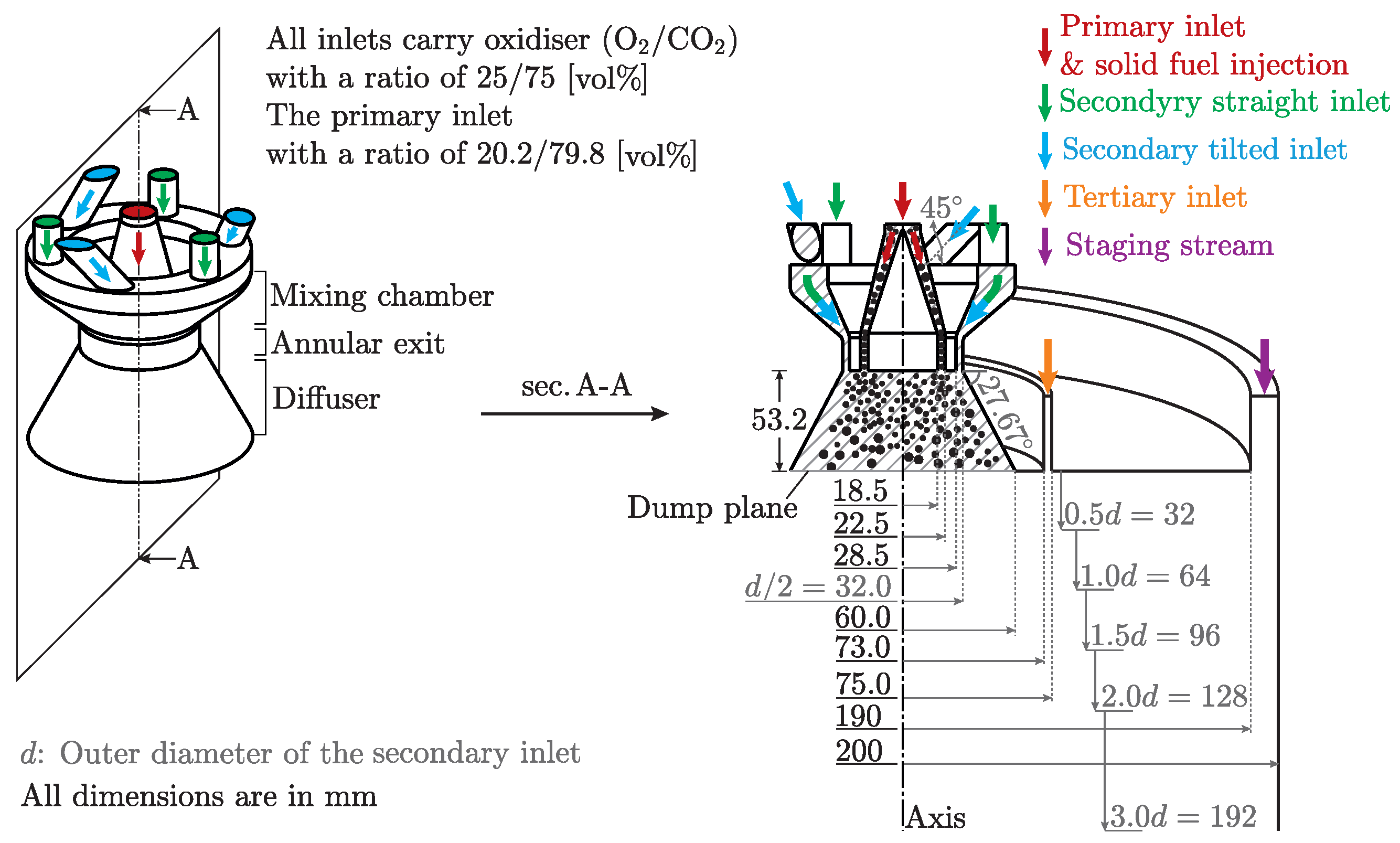
A 60 kWth pulverised downward-fired coal swirling flame under oxyfuel conditions, called OXY25 (OXY25 means that the oxidiser composition has a ratio of 25/75 vol% of O2/CO2) and experimentally characterised by Zabrodiec et al. [24], was chosen for the simulations. The cylindrical combustion chamber, schematically shown in Figure 2, had a diameter of 0.4 m and a total height of 4.2 m.
The special design of the burner on the top of the combustion chamber—see also Figure 2—enables the generation of swirling flows. The burner was designed for investigating stabilised flames for self-sustained as well as gas-assisted combustion [19,25,26,27,28]. The primary inlet of the burner is an annular tube centred around a bluff body, and it carries the oxidiser mixed with the pulverised solid fuel into the chamber. The secondary inlet of the burner enables the continuous adjustment of the strength of the swirl flow by varying the volume flow rates that are fed into the small mixing chamber of the secondary flow through the tilted and straight channels. In the experiments conducted by Zabrodiec et al. [24], the swirl number was estimated to be approximately 0.95 using the method described in [29]. The combustion chamber has two other inlets, namely, the tertiary and staging inlets. The tertiary inlet near the burner provides additional oxidiser into the chamber as well as the staging inlet at the chamber wall. The chamber wall was constantly heated to ≈900 °C during the experiments. For more details on the experimental setup, see Zabrodiec et al. [24].
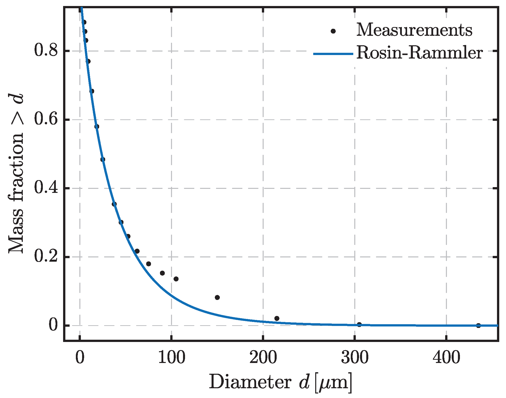
Pulverised Rhenish lignite was used as fuel; its properties are provided in Table 1 and the particle size distribution is provided in Figure 3. The mass flow rate of the pulverised solid fuel was kept constant and equal to m ˙ fuel = 9.8 kg/h [24] for all the simulations carried out in this study. The global oxygen ratio for the experiments was λ global = 1.3 [24], which is defined as the ratio of the total oxygen provided to the amount of oxygen required for complete combustion as follows:
λ = m ˙ O 2 , provided m ˙ O 2 , required .
The local oxygen ratio, defined as the provided amount of oxygen through the burner to the amount of oxygen required for complete combustion, was λ local = 0.8 [24]. The local oxygen ratio was used here to induce local variations in the particle number density in the chamber while keeping the global oxygen ratio λ global = 1.3 , the thermal output of the flame 60 kWth, and the swirl number of the secondary inlet 0.95 constant [30]. This necessitates variation in the momentum flows (volume flow rates) through the secondary and tertiary inlets and in the staging stream. In contrast, the inflow condition at the primary inlet remains unchanged. In this way, Habermehl et al. [30] observed experimentally strong influences on the flame structure. Accordingly and apart from the described case investigated by Zabrodiec et al. [24] with λ local = 0.8 , the two other cases specified in Table 2 were investigated in this study with λ local = 1.0 and λ local = 0.6 . The objective was to investigate the flame structure and the coupling behaviour for mass, momentum, energy, and turbulence between the discrete and continuous phases under the influence of different momentum flows through the burner causing different particle number densities in the chamber (discussed in detail later in Section 3).

2.2. Numerical Approach

To carry out the numerical simulations, Ansys Fluent 17.1 was used equipped with several user-defined functions (UDFs). The UDFs were written to account for the effects under oxyfuel conditions, in particular, on the kinetics of the particle phase as well as the gas absorption coefficient. The former is explained later on in this section (see Section called Particle Reaction Kinetics), and the latter was modelled by applying a modified weighted-sum-of-gray-gases model (WSGGM). The modified WSGGM is based on the model and coefficients proposed by Bordbar et al. [31], and it has already been successfully applied for the simulation of the same flame by Nicolai et al. [21] in a large-eddy simulation (LES) approach. For the coupling between the gas and particle phases, a Euler–Lagrangian scheme was considered. The details of the numerical procedure in both phases are explained below.

2.2.1. Gas Phase Modelling

For the solution of a coupled discrete–continuous phase problem under the boundary and operating conditions given in Table 2, the coupled velocity–pressure solver is used with a pseudo-transient solution strategy, where an unsteady term is added to the steady equations to improve the stability and convergence of the numerical approach [32]. In the spatial discretisation, the PRESTO scheme was used for the pressure, and the least squares cell-based method was used for the gradients. The second-order upwind method was used for the rest of the equations.
The general approach used to deal with the solution of a coupled multiphase problem of the combustion of pulverised solid fuels is to consider source terms in the governing equations of the continuous phase because of the discrete particle phase. The continuity, momentum, and energy equations can be expressed in terms of the averaged variables as follows [32,33]:
ρ t + · ρ v = S m ,
t ρ v + · ρ v v = p + μ 2 v + · γ + ρ g + F ,
t ρ E + · v ρ E + p = · k eff T j h j J j + τ ¯ ¯ eff · v + S h .
where F includes all body forces acting on the continuous phase. In Equation (3), k eff = k c + k T encompasses both the continuous phase k c and turbulent k T thermal conductivities. The diffusion flux of species j is denoted by J j .
The constitutive law proposed by Boussinesq is used to calculate the Reynolds stresses:
γ = 3 2 ρ k I + μ T 2 S ,
where μ T is an eddy viscosity, and S denotes the time-averaged rate of the deformation tensor [33]. In the k- ε model, the turbulent kinetic energy k is related to the rate of viscous dissipation ε by μ T ε = c μ ρ 2 k 2 , with c μ as a dimensionless coefficient.
The volumetric mass S m , momentum F , and heat S h sources are the connection channels between the continuous and discrete phases. Similar to the continuity, momentum, and energy equations and the transport equations for k, ε , and all the species, the source terms in each equation contain the effects of the particle phase on the continuous phase as follows:
t ρ k + · ρ k v = · μ + μ T Pr k k + G k + G b ρ ε Y M + S k ,
t ρ ε + · ρ ε v = · μ + μ T Pr ε ε + ρ C 1 S ε ρ C 2 ε 2 k + ν ε + C 1 ε ϵ k C 3 ε G b + S ε ,
with C 1 = max 0.43 η η + 5 , and η = S k ε ,
t ρ Y i + · v Y i = · J i + R i + S Y i .
with J i = ρ D i , m + μ T Sc T Y i D S , i T T , and Sc T = μ T ρ D T .
Note that Equations (1)–(6) are presented in the transient form due to the used pseudo-transient solution strategy. The source terms for the mass, S m in Equation (1), momentum, F in Equation (2), energy, S h in Equation (3), and viscous dissipation rate, S ε in Equation (5), will be described in Section 2.2.2 and evaluated in Section 4.1.
Since the flame is swirled and the nature of swirling flows has been considered in the realisable and renormalisation group (RNG) k- ε models [32], the k- ε realisable model of the RANS equations in combination with the enhanced wall treatment approach was chosen in this study to render the turbulent structure of the flame. For the modelling of the gas-phase reaction kinetics, a mechanism composed of a system of two reactions is considered as follows:
C x H y O l N m S n + 0.882 O 2 1.425 CO + 0.997 H 2 O + 0.01 N 2 + 0.004 SO 2 with x = 0.99 , y = 2.79 , l = 0.91 , m = 0.0287 , n = 0.0054 and A = 2.119 · 10 11 s 1 , and E a = 2.027 · 10 5 J / mol
and
CO + 0.5 O 2 CO 2 with A = 2.239 · 10 12 s 1 and E a = 1.7 · 10 5 J / mol ,
where A and E a are the Arrhenius pre-exponential factor and activation energy, respectively. The volatile gases are represented through a single postulated substance using the coal calculator embedded in Fluent. This approach has also been used to simulate similar flames in the same chamber [19]. For each gas species participating in the chemical reactions, the transport Equation (6) is solved, and the solution of these equations needs a closure for the chemical source terms, S Y i . This is treated by the turbulence–chemistry interaction modelling using the eddy dissipation concept (EDC). The EDC model takes into account chemical mechanisms in turbulent flows assuming the occurrence of species reactions in the fine structures of turbulence [32,34]. The chemical source terms are calculated by applying the direct integration method.

2.2.2. Particle Phase Modelling

Particle Dynamics

Particles are assumed to be spherical and are tracked using a Lagrangian reference frame [32]. In this reference frame, the momentum balance is integrated to calculate particle trajectories. Since the particle volume fraction is high in the near-burner region, a two-way coupling approach was applied to take into account the turbulence modulation of the continuous phase caused by the discrete phase. Furthermore, previous studies [20,21,22,35] have considered the inclusion of drag, gravitational, and thermophoretic forces for determining the motion of particles within the chamber.
The stochastic tracking approach with the discrete random walk model was used to account for the effect of turbulent velocity fluctuations on the particle trajectories. The number of 50 tries was determined by keeping the time scale constant of the model equal to 0.15 [32] and by repeating the simulations by increasing the number of tries until no significant changes were observed in the simulation results [36].

Turbulence Modulation by Particles

To account for turbulence modulation due to the dispersed phase, the model proposed by Al Taweel and Landau [4] is considered [32]. Accordingly, the rate of turbulent energy dissipation is calculated as follows:
ε TP = 0 15 ν κ 2 + 36 W ν d p 2 ϱ R κ 2 P ( κ ) TP d κ , R κ = 1 + b n 2 2 b n cos ϑ n
where the subscript TP stands for two phases. Note that the deviation between the particle and fluid motion generates a fluctuating relative velocity, of which the ratio to the fluctuating velocity of the fluid is represented by R κ at any particular wave number in the turbulence spectrum. In this representation, a n / B n is the amplitude ratio, and θ n is the angle of the phase lag between the fluid and particle fluctuations given in [4].

Particle Heat Transfer

For the calculation of heat transfer from/to a particle during the combustion process in the chamber, the following energy balance is applied:
m p c p d T p d t = α A p T g T p Q ˙ convection f h d m p d t H reac Q ˙ reaction + ϵ p A p σ θ p 4 T p 4 Q ˙ radiation , θ p = G 4 σ 1 4 and G = 0 4 π I s d Ω .
In Equation (8), the heat released from the particle is denoted by H reac , and the coefficient f h signifies that part of the heat released is absorbed directly by the particle and that the rest is released in the gas phase [32,37].
The calculation of the convective heat transfer coefficient h is carried out according to the empirical correlation first proposed by Frössling [38] and later on modified by Ranz and Marshall [39] as follows:
Nu d = α d p k = 2 + 0.6 Re d p 1 2 Pr 1 3 , Pr = c p , g μ k and Re d p = ρ d p v p v g μ ,
where Nu d is the particle Nusselt number, and Re d is the particle Reynolds number. The calculated heat transfer to/from a particle using Equation (8) is considered a heat sink/source in the energy balance equation of the continuous phase.

Particle Reaction Kinetics

The accurate modelling of the particle reaction kinetics is of significant importance in characterising the flame. Reactive solid fuel particles undergo two main subprocesses in a high-temperature medium, i.e., devolatilisation and char conversion. The kinetic parameters of these subprocesses are affected under oxyfuel conditions. According to [40,41,42], using simplified models for devolatilisation and char conversion can deliver good agreement if the kinetic parameters are accurately determined for these simple models. In this regard, the single first-order reaction (SFOR) model [43] for devolatilisation and the Baum and Street model [44,45] for char conversion are used with the kinetic parameters applied by Nicolai et al. [21].

Particle Devolatilisation

In the SFOR model [43], the devolatilisation rate is calculated as follows:
d m p ( t ) d t = K m p 1 f v , 0 m p , 0 and K = A e E a / R T p , A = 29.058 · 10 3 s 1 and E a = 42.879   kJ / mol
where f v , 0 is the mass fraction of volatiles initially present in the particle, R is the universal gas constant, and m p , 0 is the initial particle mass.

Char Conversion

In the Baum and Street model [44,45], the char conversion rate is limited either by reaction kinetics or diffusion in the particle. This is performed by weighting a kinetic reaction rate R k and an effective diffusion rate D 0 , resulting in the following char conversion rate:
d m p ( t ) d t = A p ρ R T g Y i M w , i D 0 R k D 0 + R k D 0 = C 1 T p + T g / 2 3 4 d p and R k = C 2 e E / R T p ,
where coefficients C 1 and C 2 depend on the temperature and conversion agents, which are oxygen, carbon dioxide, and water vapour. The numerical values for C 1 and C 2 together with the activation energy of the reactions are given in Table 3.

2.2.3. Radiation Modelling

In the combustion of pulverised solid fuel particles, radiation plays a crucial role in the heat transfer process [47]. In this study, the radiative transfer equation (RTE) for radiation intensity was solved in the framework of the discrete-ordinate model
d I r , s d s = κ g n 2 σ T 4 π I + lim V 0 n = 1 N ϵ pn A pn σ T pn 4 π V II κ g + κ p + σ p I r , s III + σ p 4 π 0 4 π I r , s Φ s , s d Ω IV .
where
κ p = lim V 0 n = 1 N ϵ pn A pn π V , A pn = π d pn 2 4 and σ p = lim V 0 n = 1 N 1 ϵ pn 1 f pn A pn π V .
The RTE (12) describes the changes in radiation intensity I along the infinitesimal path length d s in the direction r of the solid angle Ω (the left-hand-side of the RTE). On the right-hand side of the RTE, term I describes the increase in radiation intensity due to gas emission, with n as the refractive index of the gas and κ g as the gas absorption coefficient. For the gas absorption coefficient, the modified WSGGM for oxyfuel conditions proposed by Bordbar et al. [31] was used. Term II accounts for the increase in the radiation intensity due to particle emission, and the third term, term III, accounts for the intensity loss due to gas absorption, particle absorption, and outscattering, where σ p is the particle scattering coefficient. The particle emissivity and scattering factors were considered equal to ϵ p = 0.9 and f p = 0.9 , respectively [48,49,50]. Gas scattering was considered to be negligible compared to particle scattering [32,51]; thus, the scattering coefficient σ p and scattering phase function Φ of particles determine the in-scattered radiation. The scattering phase function Φ was modelled using an anisotropic Mie-scattering phase function, which is approximated by a finite series of Legendre polynomials [52,53].
The emissivity of the burner block on the top of the chamber was set to ϵ b = 0.3 , and that of the chamber wall was ϵ w = 0.7 [19].

2.2.4. Developed Numerical Solver

Figure 4 shows interfaces in Fluent, where a UDF is coupled to the developed solver used in this study. In the modelling of the discrete phase, the DEFINE_DPM_SOURCE module was used to include the heat and mass exchange between the discrete and continuous phases. For this purpose, the DEFINE_DPM_LAW and DEFINE_DPM_SWITCH modules were used under custom laws to write the UDFs for particle kinetic laws (drying, devolatilisation, and char burnout) for considering the effects of oxyfuel conditions on the particle conversion.
The DEFINE_WSGGM_ABS_COEFF module was used to account for the effect of oxyfuel conditions on the gas radiation by modifying the standard WSGGM according to Bordbar et al. [31]. In addition, anisotropic Mie-scattering was implemented according to [52,53] using the DEFINE_SCATTERING_PHASE_FUNC module. For particle radiation interactions, the DEFINE_DOM_SOURCE module was employed. The tree diagram shown in Figure 4 provides a general overview of the developed solver including the UDFs directly connected to the Fluent interfaces. The developed solver will be published by the library of the RWTH Aachen University at https://doi.org/10.18154/RWTH-2024-01307.

3. Results

In this section, first, the verification and validation of the numerical solution are presented followed by the results of the solution of the case studies introduced in Section 2.1. After the characterisation of the case studies in Section 3.2, detailed discussions on the results will be provided in Section 4.

3.1. Verification and Validation

Verification and validation studies were conducted for Case #2 with λ local = 0.8 (see Table 2) investigated by Zabrodiec et al. [24]. To verify the numerical approach, simulations with a coarse and a fine grid were carried out, and comparisons were conducted for the gas-phase velocity profiles (two left columns in Figure 5). Overall, minor discrepancies were observed in the gas-phase velocity profiles between the coarse grid with 744,495 grid cells and the fine grid with 3,309,960 grid cells, indicating the suitability of the coarse grid for subsequent investigations. The minimum and maximum cell sizes of the coarse grid were 0.35 mm in the diffuser and 1 cm near the outlet. The minimum orthogonal quality of the mesh was 0.63, and the maximum orthogonal skewness was 3.7.
For validation, the numerical solution was compared to the experimental data provided by Zabrodiec et al. [24] as well as to the LES results from Nicolai et al. [21]. Since the validation of the applied numerical approach has been shown in several studies [22,35], here, a comparison of the velocity profiles is provided in Figure 5 only for two different distances from the dump plane (diffuser outlet shown in Figure 2) (Concerning the experimental data, measurements of the particle temperature are available in [21,54], but are not compared here with the numerical results to avoid repetition with the authors’ other published work). These distances are specified by a characteristic length d, which is the outer diameter of the secondary inlet of the burner (see also Figure 2). A comparison of the particle velocity components (two right columns in Figure 5) with the experimental data [24] and also with the LES results [21] of Case #2 shows good agreement.

3.2. Solution of the Case Studies

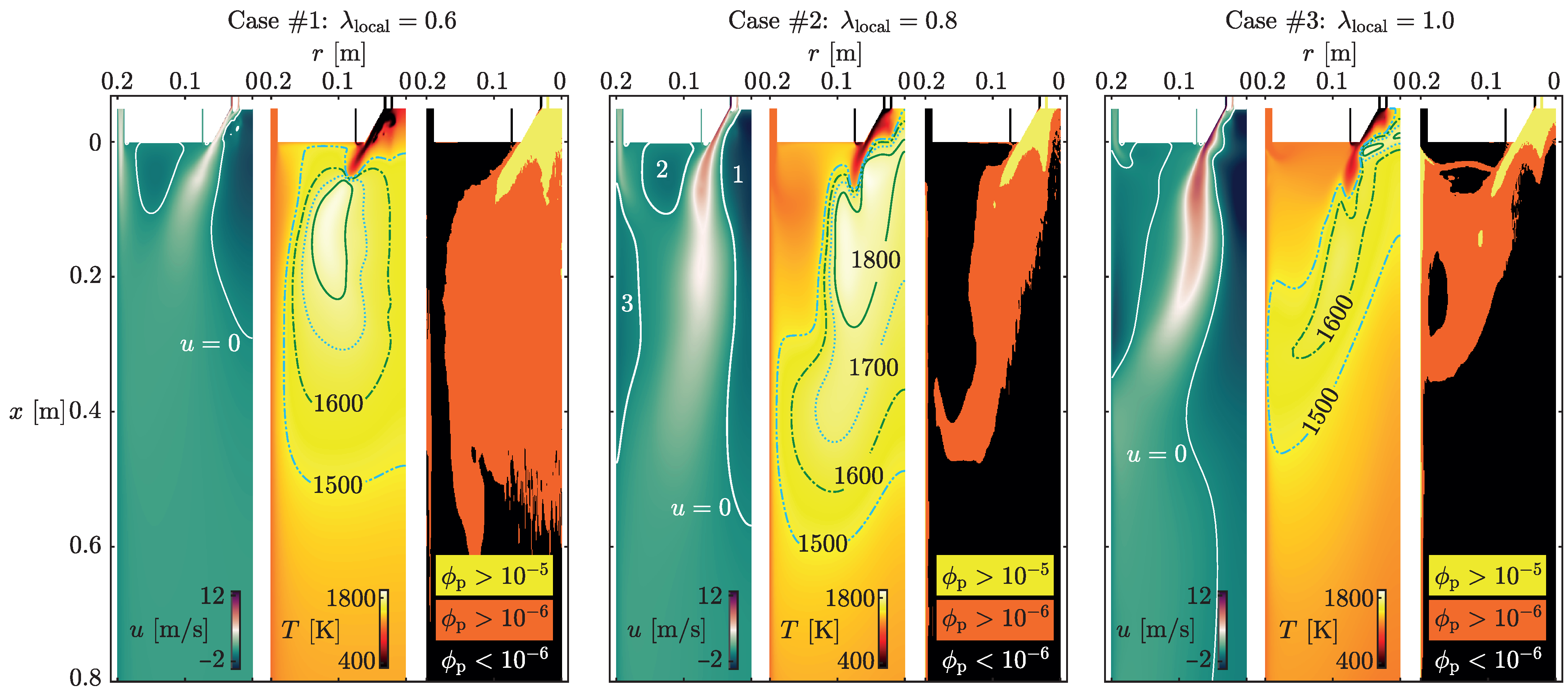
The validated numerical approach was employed to solve the case studies outlined in Section 2.1, differing solely in the local oxygen ratio, λ local , and, consequently, in the momentum flows introduced into the chamber through the inlets. Figure 6 shows the flame structure of each case characterised by the axial velocity and temperature fields as well as the distribution of particle volume fraction (PVF) in the chamber. The difference in the distribution of the PVF or particle number densities in the chamber is a result of the variation of λ local . In general, changing λ local causes substantial differences in the flame aerodynamics, temperature field, and the particle number densities in the chamber. In the following, the results for the three cases obtained using a two-way coupling approach are explained.

3.2.1. Case #1, λ local = 0.6

The axial velocity field of Case #1 with a λ local = 0.6 is characterised through (a) a relatively small inner recirculation zone (RZ) around the axis, (b) an external RZ between the burner and the staging stream, and (c) a strong staging stream. A smaller λ local in comparison to the other cases means lower/weaker momentum flows through the burner. Hence, to keep the swirl number constant, the tangential velocity component must be reduced, which results in a relatively smaller inner RZ. The external RZ is a wake zone between the staging stream and the flows through the burner. Since λ local is small, the volume flow rate of the staging stream must be increased so that λ global = 1.3 remains constant. Thus, the relatively strong staging stream directs the flame toward the axis of the chamber (see the temperature field for this case) and results in low particle number densities near the chamber wall. High particle number densities are found in this case around the axis. Note that the PVF ( ϕ p ) was characterised by the boundary value of 10 6 between the one-way and two-way coupling schemes for dilute flows suggested from the regime map (see Figure 1). This means that interactions between the discrete and the continuous phases, such as mass, momentum, and energy exchange as well as turbulence modulation, should be handled in a two-way manner. However, the orange and black regions with ϕ p < 10 5 indicate that the PVF in the chamber is mostly close to the boundary value of 10 6 . Hence, this suggests that the error of using one-way coupling can be negligible, which will be addressed in Section 4.

3.2.2. Case #2, λ local = 0.8

Case #2 with λ local = 0.8 was experimentally investigated and characterised by Zabrodiec et al. [24]. This case exhibits three RZs in the axial velocity field: (1) an inner RZ around the axis of the chamber that is relatively larger than that of Case #1, (2) the external RZ between the tertiary inlet and staging stream, and (3) the wall RZ in front of the staging stream. The inner RZ brings the hot products of the combustion process back to the diffuser and contributes in this way to the flame stability [19,24]. In comparison to Case #1, a higher λ local necessitates reduction in the staging stream to keep λ global = 1.3 . Therefore, the wall RZ appears in Case #2, which directs the staging stream toward the flame preventing the flame from spreading toward the chamber wall (see the temperature field of Case #2). This can be observed from the temperature field and the distribution of the particles ( ϕ p ) in the chamber.

3.2.3. Case #3, λ local = 1.0

Increasing the local oxygen ratio to λ local = 1.0 in Case #3 substantially changes the flame aerodynamics. The inner RZ in Case #3 is approximately 1.6 times longer than that of Case #2. In addition, the external and the wall RZs are merged and prevent the axial passage of the staging streamm which then flows radially into the wall RZ. This happens since the adjustment of the volume flow rates to keep a constant global oxygen ratio necessitates a reduction of up to 40% in the staging stream compared to Case #2 (see also Table 2). Consequently, the staging stream is not strong enough to separate the wall and external RZs. Contrarily, the secondary volume flow rate has to be increased up to 32% in comparison to Case #2. This means that to keep a constant swirl number at the secondary inlet, the swirl velocity needs to be increased accordingly. Hence, a strong swirling flow directs the flame toward the chamber wall that can be observed from the temperature field in this case. The distribution of the PVF also shows the movement of the particles toward the chamber wall.

4. Discussion

The three cases shown in Figure 6 are discussed in this section in more detail concerning the influence of the momentum flows (particle number densities) on the coupling behaviour between the particle and the gas phases in the numerical solution. The momentum flows, as shown in Figure 6, considerably change the particle number densities in the chamber, and this can affect the coupling behaviour between the discrete and the gas phases. The reciprocal influence between the particle and gas phases takes place concerning mass, momentum, turbulence, and energy transfer. In the following, these aspects are analysed for the three cases of Figure 6 in the near-burner region, where the effects of higher particle number densities are more pronounced. The 0.5 d level (see Figure 2) was chosen for the analysis in the near-burner region.

4.1. Coupling Parameters

  • Mass Coupling
To identify the coupling scheme for the mass transfer between the particle and gas phases, a mass coupling parameter can be defined according to Crowe [8] as follows:
Π mass = M ˙ d M ˙ c = n p V cell m ˙ p ρ c U A ,
where M ˙ d is the mass exchange rate of the discrete phase in a cell volume of V cell with n p particles, each with a mass exchange rate of m ˙ p , and M ˙ c is the mass flux of the continuous phase with density ρ c and velocity U through the surface area A of the volume. For the analysis here and in the following, U is the velocity magnitude.
  • Momentum Coupling
To identify the momentum coupling scheme between the particle phase and the gas phase in the investigated combustion chamber, the following definition can be used [8]:
Π momentum = F d F c = n p V cell 3 · π μ d p U U p ρ c U 2 A Re p 0.07 n p V cell 1 2 ρ U U p 2 C D π d p 2 4 ρ c U 2 A Re p > 0.07
where C D is the drag coefficient that is calculated based on the particle Reynolds number and the correlations given by Morsi and Alexander [55].
  • Energy Coupling
The identification of the energy coupling between the discrete and the continuous phase follows a similar procedure used for the mass and momentum coupling. Accordingly and in taking into account the mechanisms of heat transfer in the particle and gas phases, the coupling parameter is defined as [8]
Π energy = Q ˙ d E ˙ c = n p V cell Q ˙ convection + Q ˙ radiation + Q ˙ reaction ρ c U c p T A ,
where Q ˙ convection , Q ˙ reaction , and Q ˙ radiation are the terms on the right-hand side of Equation (8).
  • Turbulence Coupling
Following a similar proedure, the following parameter can be defined to evaluate the coupling scheme for turbulence:
Π turbulence = n p V cell Q ˙ d ρ c U k ,
where k is the turbulent kinetic energy of the continuous phase, and Q ˙ d is the turbulent kinetic energy source of the particles.

4.2. Evaluation of the Coupling Parameters

In the following, the coupling parameters defined in Section 4.1 are evaluated using the solution results obtained in Figure 6 with two-way coupling schemes. In general, if Π is of O ( 1 ) or Π 1 , then the effects of the discrete phase on the continuous phase are significant and shall be considered. Figure 7 shows that this condition is fulfilled in the near-burner region for all three cases concerning the mass transfer coupling. However, in contrast to Case #1 and Case #2, the results for Case #3 indicate a decreasing influence of the particle phase in the near-burner region when the local oxygen ratio λ local is increased. In other words, the higher velocities in this region imply shorter residence times for the particles and accordingly result in a reduction in the particle mass exchange with the gas phase. Note that all cases have a pronounced local minimum in the profiles, indicating the effect of the secondary flow with high axial velocities, which leads to a local and sudden decrease in the influence of the discrete phase on the continuous phase.
For the downstream region, however, the results for all three cases show negligible influence of the particle phase on the mass transfer and are not presented here. This is also the case for the other coupling parameters discussed in the following.
Regarding momentum coupling in Figure 7, Π momentum < O ( 0.1 ) holds for all cases except for λ local = 0.6 in the near-burner region where Π momentum is two orders of magnitudes less than 1. Generally, the order of magnitude of Π momentum is less than 0.1 for the investigated cases. Therefore, the influence of the particles on the momentum of the continuous phase is generally less important than their influence on the mass transfer. Therefore, the influence of the drag forces exerted by particles on the momentum of the gas phase can be negligible. An important reason for the small order of magnitudes of Π momentum is the decreases in particle diameter and particle density during the combustion process, which leads to a negligible difference between the particle and gas velocities. This is due to the response time of particles calculated as
τ p = ρ p d p 2 18 μ 1 Re p 0.07 24 C D Re Re p > 0.07
which become much smaller than the characteristic time associated with the flow field calculated as τ F = L cell / U , where L cell is the length of the cell. This gives the particles sufficient time to react to changes in the flow velocity, leading to almost equal velocities for both phases and hence, small drag forces affecting the continuous phase. This suggests that momentum coupling can be taken into account in a one-way scheme without high errors occurring in the simulation of the combustion chamber analysed here, especially if the results downstream of the flame are of interest. Note that reducing λ local increases the importance of the influence of the particle phase on the continuous phase concerning momentum coupling, which is due to the subsequent decrease in the continuous phase velocity.
The relevant literature also suggests a reduction in the drag force on the reacting particles [12,14]. Indeed, surface and gas phase reactions lead to a different flow pattern around reacting particles compared to a non-reactive case. In particular, the gases mobilised by surface reactions into the continuous phase affect the fluid flow around reacting particles, leading to lower drag forces on the particles [12,14].
Concerning energy exchange between the particle and the gas phases, Figure 7 shows the significant local effects of particles on the continuous phase in Case #1 and Case #2, since Π energy in these cases is of the order of 1 ( O ( 1 ) ) . Case #3 exhibits a lower influence of particles on the gas temperature field with one order of magnitude difference. Thus, the energy coupling must be considered in a two-way scheme.
For turbulence coupling, the evaluation of Π turbulence for all the three cases in Figure 7 signifies that one-way turbulence coupling can be an acceptable assumption in the case studies here with negligible errors. This means that the influence of the particles on the turbulence characteristics of the flame is negligible with regard to the modulation of the turbulence by particles. Note, however, that the regime map in Figure 1 suggests a two-way coupling approach since the PVF in the near burner region for all three cases is local to ϕ p > 10 6 (see Figure 6). However, this suggestion is a preliminary inference drawn from the regime map depicted in Figure 1. To formulate more definitive conclusions, it is imperative to evaluate the coupling parameter.

4.3. One-Way versus Two-Way Coupling

Figure 8 presents simulation results from Case #2 obtained for three different scenarios, where mass and energy were treated in a two-way manner for all scenarios investigated.
In contrast to the mass and energy coupling schemes, the coupling scheme for turbulence and momentum was varied in the following manner: (1) two-way coupling was applied for both turbulence and momentum (black dotted line); (2) one-way coupling was applied for turbulence and two-way for momentum (solid green line); and (3) turbulence and momentum were treated in a one-way manner (dashed red line). The following conclusions can be drawn from these scenarios, considering the first scenario as the reference one with two-way coupling schemes for all parameters:
  • The influence of the one-way coupling scheme for momentum on the results is hardly recognisable both for the near-burner ( 0.5 d) and the downstream ( 6.0 d) regions, comparing the red dashed line with the green solid line. This is due to the small differences between particle and gas velocities.
  • The influence of the one-way coupling for turbulence on the results obtained for the downstream region ( 6.0 d) is negligible, comparing the black dotted line with the red dashed line. One of the reasons is the higher viscosity of the hot flue gas in the downstream region compared to the viscosity of the gas in the near-burner region.
  • Neglecting the two-way coupling approach for turbulence results in small deviations between the scenarios in the near-burner region due to the high particle volume fraction. These deviations are negligible for the axial and tangential velocity components, but slightly larger for temperature and turbulence kinetic energy (TKE). This is due to the differences in the calculated effective viscosity and thermal conductivity, which directly influence the velocity and temperature of the gas phase.
Similar behaviour was observed for both Case #1 with λ local = 0.6 and Case #3 with λ local = 1.0 , whereby Case #1 showed slightly larger deviations, as can be expected based on Figure 7, since the orders of magnitude for Π momentum and Π turbulence increase with a decrease in λ local .

5. Conclusions

In this study, the importance of coupling schemes between the continuous phase and the discrete phase in the numerical simulation of pulverised solid fuel swirl flames under oxyfuel conditions in a pilot-scale combustion chamber was investigated concerning mass, momentum, energy, and turbulence coupling. For this purpose, a validated numerical tool based on the Reynolds-averaged Navier–Stokes (RANS) eddy viscosity models was developed. In using the numerical tool, the effects of different particle number densities in the chamber on the coupling schemes were studied. To identify one-way or two-way coupling schemes between the mass, momentum, energy, and turbulence of the continuous phase and the particle phase, respective coupling parameters were evaluated in the near-burner region where the particle volume fraction was high. These evaluations were performed on the results obtained by applying two-way coupling schemes for all parameters. The results show a strong coupling behaviour for mass and energy transfer for all cases, signifying the importance of two-way coupling. The evaluation of the momentum coupling indicated reduced drag forces being applied on the particles. This is due to the decreases in particle diameter and particle density during the combustion process, which led to a reduction in the difference between the particles and gas velocities. However, reducing the local oxygen ratio increased the influence of particles on the momentum of the gas phase since the gas phase velocities were dramatically reduced in the near-burner region. As far as turbulence coupling was concerned, the influence of turbulence modulation by particles on the turbulence characteristics of the gas phase can be important only in the regions with high particle volume fractions (in the diffuser area of the burner) due to the direct influence on the calculation of the effective viscosity and thermal conductivity, which directly affects the velocity and temperature of the continuous phase. However, the deviations caused by neglecting particle turbulence modulation on the flame characteristics were small, emphasising the naturalising effect suggested by the regime map on the turbulence of the gas phase due to the wide range of particle diameters flying in the chamber. These results are limited to (1) neglecting fragmentation in the particle oxidation and gasification models, which can affect the heat and mass exchange between the phases, and (2) calculating the heat transfer coefficient between the particle and the gas phase using a correlation developed for a single evaporating, falling droplet with a boundary layer that remains undisturbed by the other particles.

Author Contributions

H.A.: conceptualisation, methodology, investigation, validation, software, data curation, formal analysis, writing—original draft preparation, writing—review and editing, and visualisation; S.P.: conceptualisation, methodology, formal analysis, writing—review and editing, visualisation, and supervision; H.N.: conceptualisation, data curation, validation, writing—review and editing, and supervision; A.M.: conceptualisation, resources, validation, writing—review and editing, supervision, project administration, funding acquisition; R.K.: resources, writing—review and editing, supervision, project administration, and funding acquisition; C.H.: writing—review and editing, project administration, and funding acquisition; All authors have read and agreed to the published version of the manuscript.

Funding

This research was funded by Deutsche Forschungsgemeinschaft (DFG, German Research Foundation)—Funding number 215035359—FB/TRR 129 Oxyflame.

Institutional Review Board Statement

Not applicable.

Informed Consent Statement

Not applicable.

Data Availability Statement

The data of the manuscript will be published by the library of the RWTH Aachen University at https://doi.org/10.18154/RWTH-2024-01307.

Acknowledgments

H. Askarizadeh thanks his former student Petar Petrovic for the preliminary 2D simulations of turbulence modulation by particles, which he carried out as part of his Bachelor thesis.

Conflicts of Interest

The authors declare no conflicts of interest.

Abbreviations

The following abbreviations are used in this manuscript:
DNSDirect numerical simulation;
EDCEddy dissipation concept;
HHVHigher heating value;
LESLarge-eddy simulation;
OXY2560 kWth Oxyfuel flame (oxidiser composition of a ratio of 25/75 vol% of O2/CO2);
PVFParticle volume fraction;
RANSReynolds-averaged Navier–Stokes;
RBKRhenish lignite (Rheinische Braunkohle);
RHSRight-hand side;
RNGRenormalisation group;
RTERadiative transfer equation;
RZRecirculation zone;
SFORSingle first-order reaction;
TKETurbulence kinetic energy;
UDFUser-defined function;
WSGGMWeighted-sum-of-gray-gases model.

Nomenclature

A Pre-exponetial factor [J m−1 K−1] γ Boussinesq approximation [kg m−1 s−2]
ASurface area [m2] ε Viscous dissipation rate [m2 s−3]
b n Amplitude ratio [-] ϵ Emissivity [-]
cSpecific heat capacity [s−1] θ Radiation temperature [K]
CDrag coefficient [-] ϑ n Phase lag angle between fluid
dDiameter [m] θ Radiation temperature [K]
DEffective diffusion rate [s m−1] ϑ n Phase lag angle between fluid and particle flactuations [Rad]
ETotal enthalpy [m2 s−2]
F External body forces [N] κ Wavenumber in Equation (7) [m−1], and Absorption coefficient in Equation (12) [m−1]
fScattering factor [-], and  f h is the fraction of heat absorbed by particles [-] λ Oxygen ratio [-]
g Gravitational acceleration [m s−2] μ Dynamic viscosity [kg m−1 s−1]
G Turbulence generation [W m−3] ν Kinematic viscosity [m2 s−1]
GIncident radiation over all solid angles [W] ρ Density [kg m−3]
hSensible enthalpy [m2 s−2] ϱ Density ratio (particle to fluid) [-]
HReaction enthalpy [m2 s−2] σ Scattering coefficient in Equation (12) [m−1], and Stefan–Boltzmann constant in Equations (8) and (12) [W m−2 K−4]
I Identity matrix [-]
IRadiation intensity [W m−2]
J Diffusion flux [kg m−2 s−1] τ Relaxation time/time scale [s]
kThermal conductivity Equation (3) [W m−1 K−1] Turbulent kinetic energy Equation (4) [m2 s−2] τ ¯ ¯ Stress tensor [Pa]
ϕ Volume fraction [-]
K Arrhenius kinetic rate [s−1] Φ Phase function [-]
mMass [kg] Ω Solid angle [Steradian]
MMolar mass [kg mol−1]
nRefractive index [-]Subscripts
N Total number of particles 1 ε , 2 ε , 3 ε Constants in Equation (5)
pPressure [Pa]aActivation energy
PFraction of TKE associated with the wavenumber κ [-]cContinuous phase
dDiscrete
r Position vector [m]DDrag
RUniversal gas constant Equation (11) [J mol−1] Net rate of species production in Equation (6) [kg s−1 m−3]effEffective
gGas
hHeat source
R Ratio of the fluctuating relative velocity to that of the continuous phase [-]hHeat absorbed by particles in Equation (8)
i, jCounter
s Direction vector [m]kTurbulent kinetic energy
SSource term κ Wavenumber Equation (7)
S Time-averaged rate of deformation tensor [s−1]mMass source
pPressure
mMasssDirection, Equation (8)
pParticle [T]TPTwo-phase
UAxial velocity [m s−1]TTurbulence
v Velocity vector [m s−1] Y i Species
VVolume of a computational cell [m3]
WParticle weight concentrationDimensionless numbers
Y M Compressibility effects [W m−3]NuNusselt number
YOxidant mass fraction [-]PrPrandtl number
ReReynolds number
GreeklettersScSchmidt number
α Convective heat transfer coefficient [W m−2 K−1]StStokes number

References

  1. Hoque, M.M.; Joshi, J.B.; Evans, G.M.; Mitra, S. A critical analysis of turbulence modulation in particulate flow systems: A review of the experimental studies. Rev. Chem. Eng. 2023, 40, 511–544. [Google Scholar] [CrossRef]
  2. Einstein, A. Eine neue Bestimmung der Moleküldimensionen. Ann. Phys. 1906, 324, 289–306. [Google Scholar] [CrossRef]
  3. Eirich, F.; Bunzl, M.; Margaretha, H. Untersuchungen über die Viskosität von Suspensionen und Lösungen. 4. Über die Viskosität von Kugelsuspensionen. Kolloid Z. 1936, 74, 276–285. [Google Scholar] [CrossRef]
  4. Al Taweel, A.M.; Landau, J. Turbulence modulation in two-phase jets. Int. J. Multiph. Flow 1977, 3, 341–351. [Google Scholar] [CrossRef]
  5. Hetsroni, G. Particles-turbulence interaction. Int. J. Multiph. Flow 1989, 15, 735–746. [Google Scholar] [CrossRef]
  6. Crowe, C.T. On models for turbulence modulation in fluid–particle flows. Int. J. Multiph. Flow 2000, 26, 719–727. [Google Scholar] [CrossRef]
  7. Elgobashi, S. An updated classification map of particle-laden turbulent flows. In IUTAM Symposium on Computational Approaches to Multiphase Flow; Fluid Mechanics and Its Applications; Balachandar, S., Prosperetti, A., Eds.; Springer: Dordrecht, The Netherlands, 2006; Volume 81, pp. 3–10. [Google Scholar] [CrossRef]
  8. Crowe, C.T. Multiphase Flows with Droplets and Particles, 2nd ed.; CRC Press: Boca Raton, FL, USA, 2012. [Google Scholar] [CrossRef]
  9. M Kuerten, J.G. Point-particle DNS and LES of particle-laden turbulent flow—A state-of-the-art review. Flow Turbul. Combust. 2016, 97, 689–713. [Google Scholar] [CrossRef] [PubMed]
  10. Elghobashi, S.; Abou-Arab, T.; Rizk, M.; Mostafa, A. Prediction of the particle-laden jet with a two-equation turbulence model. Int. J. Multiph. Flow 1984, 10, 697–710. [Google Scholar] [CrossRef]
  11. Gore, R.A.; Crowe, C.T. Effect of particle size on modulating turbulent intensity. Int. J. Multiph. Flow 1989, 15, 279–285. [Google Scholar] [CrossRef]
  12. Farazi, S.; Sayadi, T.; Pitsch, H. Numerical analysis of the drag force acting on the reactive single char particle under oxy-fuel condition. In Proceedings of the China National Symposium on Combustion, Ma’anshan, China, 21–23 October 2016. [Google Scholar]
  13. Fröhlich, K.; Schneiders, L.; Meinke, M.; Schröder, W. Validation of Lagrangian two-way coupled point-particle models in large-eddy simulations. Flow Turbul. Combust. 2018, 101, 317–341. [Google Scholar] [CrossRef]
  14. Jayawickrama, T.R.; Haugen, N.E.L.; Babler, M.U.; Chishty, M.A.; Umeki, K. The effect of Stefan flow on the drag coefficient of spherical particles in a gas flow. Int. J. Multiph. Flow 2019, 117, 130–137. [Google Scholar] [CrossRef]
  15. Zhang, H.; Luo, K.; Haugen, N.E.L.; Mao, C.; Fan, J. Drag force for a burning particle. Combust. Flame 2020, 217, 188–199. [Google Scholar] [CrossRef]
  16. Llamas, Á.D.G.; Guo, N.; Li, T.; Gebart, R.; Umeki, K. Rapid change of particle velocity due to volatile gas release during biomass devolatilization. Combust. Flame 2022, 238, 111898. [Google Scholar] [CrossRef]
  17. Du, S.; Zhao, L.; Chen, X.; Yang, B.; Zhou, Q. Effect of Stefan flow on the drag force of single reactive particle surrounded by a sea of inert particles. Chem. Eng. Sci. 2022, 253, 117546. [Google Scholar] [CrossRef]
  18. Hasse, C.; Debiagi, P.; Wen, X.; Hildebrandt, K.; Vascellari, M.; Faravelli, T. Advanced modeling approaches for CFD simulations of coal combustion and gasification. Prog. Energy Combust. Sci. 2021, 86, 100938. [Google Scholar] [CrossRef]
  19. Toporov, D.; Bocian, P.; Heil, P.; Kellermann, A.; Stadler, H.; Tschunko, S.; Förster, M.; Kneer, R. Detailed investigation of a pulverized fuel swirl flame in CO2/O2 atmosphere. Combust. Flame 2008, 155, 605–618. [Google Scholar] [CrossRef]
  20. Sadiki, A.; Agrebi, S.; Chrigui, M.; Doost, S.; Knappstein, R.; Di Mare, F.; Janicka, J.; Maßmeyer, A.; Zabrodiec, D.; Hees, J.; et al. Analyzing the effects of turbulence and multiphase treatments on oxy-coal combustion process predictions using LES and RANS. Chem. Eng. Sci. 2017, 166, 283–302. [Google Scholar] [CrossRef]
  21. Nicolai, H.; Wen, X.; Miranda, F.; Zabrodiec, D.; Maßmeyer, A.; Di Mare, F.; Dreizler, A.; Hasse, C.; Kneer, R.; Janicka, J. Numerical investigation of swirl-stabilized pulverized coal flames in air and oxy-fuel atmospheres by means of large eddy simulation coupled with tabulated chemistry. Fuel 2020, 287, 119429. [Google Scholar] [CrossRef]
  22. Askarizadeh, H.; Nicolai, H.; Zabrodiec, D.; Pielsticker, S.; Hasse, C.; Kneer, R.; Maßmeyer, A. Numerische Untersuchung zur Relevanz von Teilmodellen für Pyrolyse und Koksabbrand in turbulenten drallbehafteten Flammen unter Oxyfuel-Bedingungen. In Proceedings of the 30. Deutscher Flammentag, Hannover, Germany, 28–29 September 2021. [Google Scholar] [CrossRef]
  23. Russo, E.; Kuerten, J.G.M.; Geurts, B.J. Delay of biomass pyrolysis by gas–particle interaction. J. Anal. Appl. Pyrolysis 2014, 110, 88–99. [Google Scholar] [CrossRef]
  24. Zabrodiec, D.; Becker, L.; Hees, J.; Maßmeyer, A.; Habermehl, M.; Hatzfeld, O.; Dreizler, A.; Kneer, R. Detailed analysis of the velocity fields from 60 kW swirl-stabilized coal flames in CO2/O2- and N2/O2-atmospheres by means of laser Doppler velocimetry and Particle Image Velocimetry. Combust. Sci. Technol. 2017, 189, 1751–1775. [Google Scholar] [CrossRef]
  25. Becker, L.; Kosaka, H.; Böhm, B.; Doost, S.; Knappstein, R.; Habermehl, M.; Kneer, R.; Janicka, J.; Dreizler, A. Experimental investigation of flame stabilization inside the quarl of an oxyfuel swirl burner. Fuel 2017, 201, 124–135. [Google Scholar] [CrossRef]
  26. Schneider, H.; Valentiner, S.; Vorobiev, N.; Böhm, B.; Schiemann, M.; Scherer, V.; Kneer, R.; Dreizler, A. Investigation on flow dynamics and temperatures of solid fuel particles in a gas-assisted oxy-fuel combustion chamber. Fuel 2021, 286, 119424. [Google Scholar] [CrossRef]
  27. Özer, B.; Zabrodiec, D.; Kneer, R.; Maßmeyer, A. Experimental investigation of 40 kWth methane-assisted and self-sustained pulverized biomass flames. Proc. Combust. Inst. 2023, 39, 3343–3351. [Google Scholar] [CrossRef]
  28. Axt, C.; Maßmeyer, A.; Pielsticker, S.; Kneer, R. Spatially-resolved experimental investigations of combustion characteristics in a solid fuel doped methane swirl flame and the influence on the formation of ultrafine particulate matter. Combust. Flame 2022, 244, 112223. [Google Scholar] [CrossRef]
  29. Chigier, N.A.; Beeé, J.M. Velocity and static-pressure distributions in swirling air jets issuing from annular and divergent nozzles. J. Basic Eng. 1964, 86, 788–796. [Google Scholar] [CrossRef]
  30. Habermehl, M.; Hees, J.; Maßmeyer, A.; Zabrodiec, D.; Hatzfeld, O.; Kneer, R. Comparison of flame stability under air and oxy-fuel conditions for an aerodynamically stabilized pulverized coal swirl flame. J. Energy Res. Technol. 2016, 138, 042209. [Google Scholar] [CrossRef]
  31. Bordbar, M.H.; Węcel, G.; Hyppänen, T. A line by line based weighted sum of gray gases model for inhomogeneous CO2–H2O mixture in oxy-fired combustion. Combust. Flame 2014, 161, 2435–2445. [Google Scholar] [CrossRef]
  32. ANSYS Fluent 17.1 Theory Guide; ANSYS, Inc.: Canonsburg, PA, USA, 2016.
  33. Pozrikidis, C. Fluid Dynamics: Theory, Computation, and Numerical Simulation; Springer Science+Business Media: New York, NY, USA, 2016. [Google Scholar] [CrossRef]
  34. Magnussen, B. On the structure of turbulence and a generalized eddy dissipation concept for chemical reaction in turbulent flow. In Proceedings of the 19th Aerospace Sciences Meeting, St. Louis, MO, USA, 12–15 January 1981; p. 42. [Google Scholar]
  35. Askarizadeh, H.; Koch, M.; Nicolai, H.; Pielsticker, S.; Kneer, R.; Hasse, C.; Maßmeyer, A. Influence of gas radiation, particle radiation interactions, and conversion-dependent particle radiative properties on pulverized solid fuel combustion. In Proceedings of the 31. Deutscher Flammentag, Berlin, Germany, 27–28 September 2023. [Google Scholar]
  36. Benim, A.C.; Deniz Canal, C.; Boke, Y.E. A validation study for RANS based modelling of swirling pulverized fuel flames. Energies 2021, 14, 7323. [Google Scholar] [CrossRef]
  37. Boyd, R.K.; Kent, J.H. Three-dimensional furnace computer modelling. Symp. (Int.) Combust. 1988, 21, 265–274. [Google Scholar] [CrossRef]
  38. Frössling, N. Über die Verdunstung fallender Tropfen. Gerlands Beitr. Geophys. 1938, 52, 170–216. [Google Scholar]
  39. Ranz, W.E.; Marshall, W.R., Jr. Evaporation from drops. Part I and Part II. Chem. Eng. Prog. 1952, 48, 173–180. [Google Scholar]
  40. Nicolai, H. Towards Predictive Simulations of Low-Emission Reactive Solid Fuel Systems. Ph.D. Thesis, Technische Universität Darmstadt, Darmstadt, Germany, 2022. [Google Scholar] [CrossRef]
  41. Nicolai, H.; Debiagi, P.; Wen, X.; Dressler, L.; Maßmeyer, A.; Janicka, J.; Hasse, C. Flamelet LES of swirl-stabilized oxy-fuel flames using directly coupled multi-step solid fuel kinetics. Combust. Flame 2022, 241, 112062. [Google Scholar] [CrossRef]
  42. Nicolai, H.; Debiagi, P.; Janicka, J.; Hasse, C. Flamelet LES of oxy-fuel swirling flames with different O2/CO2 ratios using directly coupled seamless multi-step solid fuel kinetics. Fuel 2023, 344, 128089. [Google Scholar] [CrossRef]
  43. Badzioch, S.; Hawksley, P.G.W. Kinetics of thermal decomposition of pulverized coal particles. Ind. Eng. Chem. Process Des. Dev. 1970, 9, 521–530. [Google Scholar] [CrossRef]
  44. Baum, M.M.; Street, P.J. Predicting the combustion behaviour of coal particles. Combust. Sci. Technol. 1971, 3, 231–243. [Google Scholar] [CrossRef]
  45. Field, M.A.; Gill, D.W.; Morgan, B.B.; Hawksley, P.G.W. Combustion of Pulverised Coal; B.C.U.R.A.: London, UK, 1967. [Google Scholar]
  46. Gövert, B.; Pielsticker, S.; Kreitzberg, T.; Habermehl, M.; Hatzfeld, O.; Kneer, R. Measurement of reaction rates for pulverized fuel combustion in air and oxyfuel atmosphere using a novel fluidized bed reactor setup. Fuel 2017, 201, 81–92. [Google Scholar] [CrossRef]
  47. Guo, J.; Hu, F.; Jiang, X.; Li, P.; Liu, Z. Effects of gas and particle radiation on IFRF 2.5 MW swirling flame under oxy-fuel combustion. Fuel 2020, 263, 116634. [Google Scholar] [CrossRef]
  48. Backreedy, R.I.; Fletcher, L.M.; Ma, L.; Pourkashanian, M.; Williams, A. Modelling pulverised coal combustion using a detailed coal combustion model. Combust. Sci. Technol. 2006, 178, 763–787. [Google Scholar] [CrossRef]
  49. Al-Abbas, A.H.; Naser, J.; Dodds, D. CFD modelling of air-fired and oxy-fuel combustion of lignite in a 100 kW furnace. Fuel 2011, 90, 1778–1795. [Google Scholar] [CrossRef]
  50. Guo, J.; Liu, Z.; Huang, X.; Zhang, T.; Luo, W.; Hu, F.; Li, P.; Zheng, C. Experimental and numerical investigations on oxy-coal combustion in a 35 MW large pilot boiler. Fuel 2017, 187, 315–327. [Google Scholar] [CrossRef]
  51. Yin, C. On gas and particle radiation in pulverized fuel combustion furnaces. Appl. Energy 2015, 157, 554–561. [Google Scholar] [CrossRef]
  52. Kim, T.K.; Lee, H.S. Radiative transfer in two-dimensional anisotropic scattering media with collimated incidence. J. Quant. Spectrosc. Radiat. Transf. 1989, 42, 225–238. [Google Scholar] [CrossRef]
  53. Jendoubi, S.; Lee, H.S.; Kim, T.K. Discrete ordinates solutions for radiatively participating media in a cylindrical enclosure. J. Thermophys Heat Transf. 1993, 7, 213–219. [Google Scholar] [CrossRef]
  54. Zabrodiec, D.; Hees, J.; Maßmeyer, A.; vom Lehn, F.; Habermehl, M.; Hatzfeld, O.; Kneer, R. Experimental investigation of pulverized coal flames in CO2/O2- and N2/O2-atmospheres: Comparison of solid particle radiative characteristics. Fuel 2017, 201, 136–147. [Google Scholar] [CrossRef]
  55. Morsi, S.A.; Alexander, A.J. An investigation of particle trajectories in two-phase flow systems. J. Fluid Mech. 1972, 55, 193. [Google Scholar] [CrossRef]
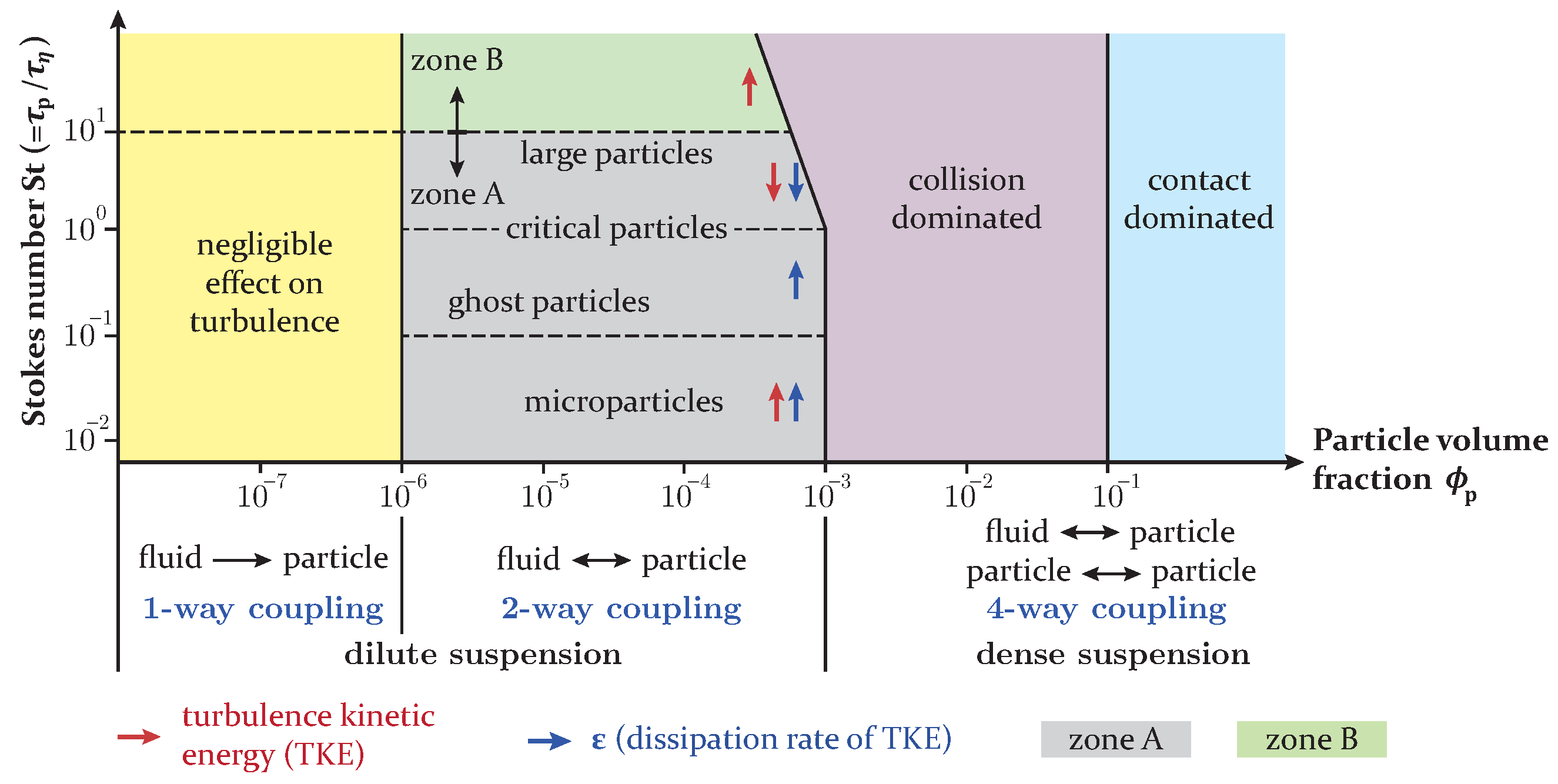
Figure 1. Regime map for the classification of different types of coupling schemes between the dispersed and continuous phases according to [7,8].
Fire 07 00185 g001
Figure 2. Schematic view of the burner and a vertical cross-sectional view of the combustion chamber. The outer diameter of the secondary inlet, d = 64 mm, is used to specify different distances in the chamber from the dump plane.
Fire 07 00185 g002
Figure 3. The Rosin–Rammler diameter distribution method for the particle size distribution obtained through laser diffraction analyses (Helos 12 Basis LA, Sympatec).
Fire 07 00185 g003
Figure 4. Tree diagram for the implemented user-defined functions (UDFs) in the solver developed in Fluent for the solution of pulverised solid fuel combustion problems under oxyfuel conditions.
Fire 07 00185 g004
Figure 5. (Left two columns) A comparison of the gas velocity components obtained from the coarse and the fine grids for the verification of the numerical solution. (Right two columns) A comparison of the particle velocity components with the experimental data given by Zabrodiec et al. [24] and with the LES from Nicolai et al. [21].
Fire 07 00185 g005
Figure 6. Influence of the local oxygen ratio λ local on the flame structure with respect to the axial velocity u and temperature T fields as well as the distribution of the particle volume fraction (PVF) ϕ p . Three cases with different local oxygen ratios of (left) λ local = 0.6 , (middle) λ local = 0.8 (Case #2), and (right) λ local = 1.0 (Case #3), were investigated. The contour lines for the temperature are specified with values for Case #2. The same values apply to the lines of the other cases with the same line pattern.
Fire 07 00185 g006
Figure 7. Evaluation of the coupling parameters for mass, momentum, energy, and turbulence exchange between the discrete and continuous phase in the near-burner region at a distance of 0.5 d from the dump plane for the three case studies. The radial position on the abscissa is limited to the regions with higher values of the coupling parameters in each case.
Fire 07 00185 g007
Figure 8. Comparison of the simulation results for the gas phase obtained using one-way and two-way coupling schemes regarding momentum and turbulence for Case #2 with λ local = 0.8 . (1-way) Only turbulence and momentum were treated in a one-way manner, (1-way turb. & 2-way mom.) only turbulence was treated in a one-way manner, and (2-way) all coupling schemes remained two-way.
Fire 07 00185 g008
Table 1. Physical and chemical properties of Rhenish lignite (RBK) according to ultimate and proximate analysis [24].
Ultimate Analysis a[wt%]Proximate Analysis b[wt%]
C69.05Ash5.440
H4.830Water12.15
N0.690Volatiles42.42
S0.300Char39.99
O25.13HHV c [MJ/kg]22.153
a reference state: dry, ash-free; b as received; c higher heating value.
Table 2. Operating and boundary conditions for case studies investigated here, which differ by λ local .
InletT [°C] V ˙ a [m3/h]O2/CO2 [vol %]
Case #1Case #2Case #3
λ local = 0 . 6 λ local = 0 . 8 λ local = 1 . 0
Primary259.49.49.420.2/79.8
Secondary4016.223.831.325/75
Tertiary402.94.25.525/75
Staging90031.322.213.325/75
a STP: standard temperature 0 °C and pressure 1.013 bar.
Table 3. Activation energy and rate constants of conversion reactions in low-temperature ( T < 950   ° C ) and high-temperature ranges [19,21,46].
Oxidiser O 2 [21,46] CO 2 ( T 950 °C) [19] CO 2 ( T > 950 °C) [19] H 2 O [19]
C 1 [ s / K 0.75 ] 7.430 · 10 13 1.0 · 10 10 1.0 · 10 10 2.84 · 10 12
C 2 [ s / m ] 188.6 1.35 · 10 4 6.35 · 10 3 1.92 · 10 3
E a [ J / mol ] 1.286 · 10 5 1.35 · 10 5 1.62 · 10 5 1.47 · 10 5
Disclaimer/Publisher’s Note: The statements, opinions and data contained in all publications are solely those of the individual author(s) and contributor(s) and not of MDPI and/or the editor(s). MDPI and/or the editor(s) disclaim responsibility for any injury to people or property resulting from any ideas, methods, instructions or products referred to in the content.