Abstract
Developing mmWave radar sensors for indoor crowd motion sensing and tracking faces a critical challenge: the scarcity of large-scale, high-quality training data. Traditional human experiments encounter logistical complexities, ethical considerations, and safety issues. Replicating precise human movements across trials introduces noise and inconsistency into the data. To address this, this study proposes a novel solution: a movable platform equipped with a life-size mannequin to generate realistic and diverse data points for mmWave radar training and testing. Unlike human subjects, the platform allows precise control over movements, optimising sensor placement relative to the target object. Preliminary optimisation results reveal that sensor height impacts tracking performance, with an optimal sensor placement above the test subject yields the best results. The results also reveal that the 3D data format outperforms 2D data in accuracy despite having fewer frames. Additionally, analysing height distribution using 3D data highlights the importance of the sensor angle—15° downwards from the horizontal plane.
1. Introduction
The rapid expansion of urban areas has led to the construction of larger and more intricate buildings and public facilities. These structures pose unique fire safety challenges compared to their smaller counterparts due to features like extended escape distances, intricate layouts, and diverse building materials [1,2]. This complexity, coupled with higher occupant densities, elevates the potential for fire casualties [3]. Despite these heightened risks, current evacuation plans typically rely on pre-defined escape routes established during construction. While these plans consider factors like legal regulations, travel time, and route capacity, their static nature limits their effectiveness in dynamic situations [4]. Static signage cannot adapt to changing environments and may direct occupants towards compromised exits blocked by fire, smoke, or congestion. This limitation is further supported by the US Fire Administration’s report on civilian fire injuries, where escape-related issues, fire patterns, and egress difficulties were identified as contributing factors in over 79% of cases [5]. Advancements in sensor technology, computational power, and communication infrastructure pave the way for the development of more sophisticated evacuation systems. Research efforts are underway to develop alternative systems that leverage real-time data from various sensors to dynamically guide occupants towards the safest exit pathways in real-time [4,6]. Real-time information on building occupants, their distribution, and numbers can also be valuable to first responders, enabling them to make informed decisions and potentially save lives during emergencies. Integrating this information with the building’s fire alert system can further enhance emergency management by informing occupants about the least congested evacuation routes for a faster escape.
Effective indoor emergency evacuation requires comprehensive data about the building environment, evolving fire hazards, and human behaviour during evacuation events [7]. Detecting and tracking human movement is crucial in such situations, and various approaches exist for this purpose. Device-free approaches are generally preferred due to their practicality, and various technologies like infrared imagers [8], cameras [9], and WiFi signals [10] have been explored for this purpose. However, infrared radiation sensors are limited by their narrow beam range and inability to detect relatively stationary objects [11]. Vision-based techniques (e.g., cameras) are widely used and perform well when given a clean environment, but they are intrusive and have lower user acceptance in domestic and commercial settings. Radio frequency-based methods such as WiFi signals are less intrusive. Unfortunately, these methods require a separate transmitter and receiver, and are limited to situations where users walk between them [12]. Among these technologies, millimetre wave (mmWave) radar technology shows promise in human movement sensing applications [13]. It is a transceiver, so only requires a single device for tracking and identification. Operating at a high-frequency range, this technology transmits short-wavelength electromagnetic signals that reflect off objects in their path. By analysing the reflected signal, the system can infer the distance and trajectory of the object. Texas Instruments (TI) [14] conducted people counting and tracking experiments using a mmWave radar sensor and it reported an accuracy of 45% for five people and 96% for one person. Huang et al. [13] proposed a new indoor people detection and tracking system using a mmWave radar sensor, and the proposed system improved the experimental accuracy ranges from 98% for one person to 65% for five people. However, this system still has limited accuracy when dealing with larger groups. Zhao et al. [15] also proposed a human tracking and identification system (mID) based on the mmWave radar. Extensive experimental results demonstrate that mID achieves an overall recognition accuracy of 89% among 12 people, with the accuracy increasing when fewer people are in the dataset. In addition, unlike vision-based methods, it can function effectively even in poorly lit or visually obscured environments [15,16], and it does not raise the same privacy concerns associated with image-based techniques.
While research demonstrates the potential of mmWave sensors for various applications [17,18,19,20], including fire safety [21,22], widespread deployment faces significant challenges [23]. Sensor performance can be significantly influenced by variations in both hardware and deployment environments. Zhao et al. [15] report that the length of time people are observed by the sensor has a significant impact on identification performance. Their results show that the percentage of the correct prediction reaches from 89% to 99% when the observation time increases from 2 s to 6 s. In addition, Huang et al. [24] demonstrate that as the number of people increases, the positional relationship and mutual occlusion between pedestrians will lead to an increase in errors. This necessitates extensive on-site testing and calibration for each project, leading to project-specific investments and hindering large-scale adoption. Additionally, generalisability limitations exist even within the field of sensor technology. While large-scale datasets can be used to develop threat recognition algorithms, any incompleteness in the data can introduce biases, leading to classification errors [25]. In the specific context of mmWave sensors and crowd dynamics detection, data collection presents unique challenges due to the inherent variability of human characteristics and behaviours, as well as the impracticality of replicating real-world environmental conditions in controlled settings. Addressing these challenges is crucial for ensuring the effectiveness development of mmWave-based crowd dynamics detection systems.
Building upon the above background, this paper reports on the development, implementation, and testing of a novel platform for generating high-quality datasets applicable to sensor performance improvement in crowd dynamics detection. This platform addresses the challenge of generalisability associated with human-subject data collection in controlled environments. The core of the platform is a human-sized mannequin mounted on a movable platform. This configuration enables the generation of repeatable and scalable scenarios with controlled variability in terms of the mannequin’s size and shape, movement speed, and trajectory. This level of control allows for the creation of diverse scenarios that mimic real-world crowd dynamics, ultimately leading to the generation of comprehensive datasets. Importantly, this approach eliminates ethical concerns surrounding human-subject involvement in experiments.
This paper presents two key contributions in the realm of mmWave radar-based crowd monitoring systems. Firstly, this work proposes a novel approach to address the knowledge gap in the existing literature by demonstrating, for the first time, the platform’s ability to generate detectable data for mmWave radars. By successfully generating data detectable by the sensor, this research lays the foundation for the further exploration of the platform’s capabilities. Secondly, this paper presents a preliminary analysis examining the impact of various physical sensor configurations on detection performance. This analysis focuses on the influence of sensor height and angle variations on the sensor’s output. By scrutinising these factors, this research provides valuable insights into optimising sensor placement and configuration for improved crowd monitoring effectiveness. The findings from this initial analysis serve as a stepping stone towards the development of more sophisticated and reliable crowd monitoring systems.
The paper is structured as follows: Section 2: Experimental Setup and Data Collection. This section outlines the experimental setup and details the data collection process employed in this study. Section 3: Validation and optimisation of the platform. This section delves into the analysis of the platform’s ability to generate trajectory and object height data in conjunction with the detection system. It also explores the potential for setup optimisation. Section 4: Significance, Applications, and Future Directions. This section discusses the platform’s significance, potential solutions it offers, and its applications. Section 5: Conclusion. This concluding section summarises the key findings and outlines potential areas for future research.
2. Methodology
2.1. Room Setup
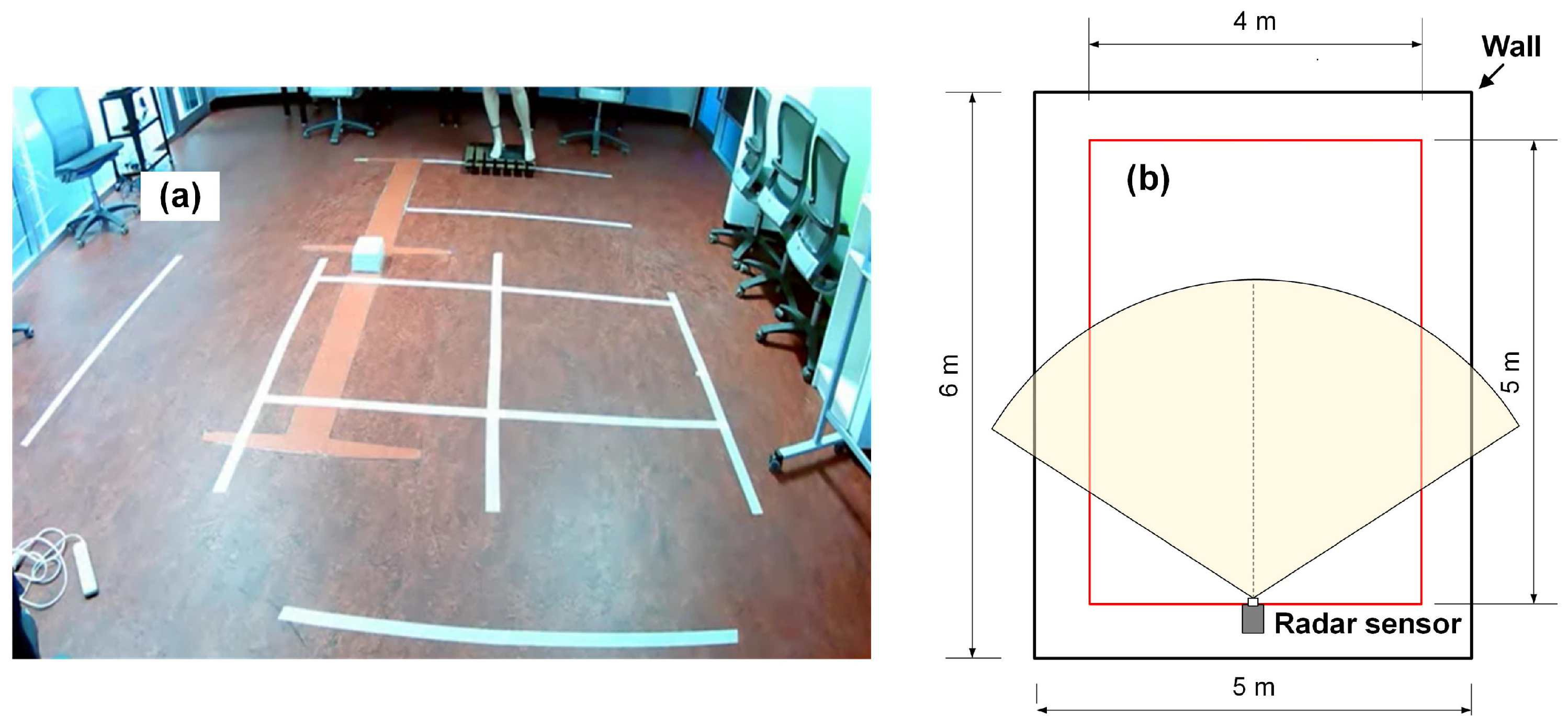
For this study, the experiments were conducted in a room measuring 6 m by 5 m on the campus of UNSW Sydney. A grid measuring 5 m × 4 m, marked on the room’s concrete floor in 1 m increments, served as a visual reference, as shown in Figure 1.
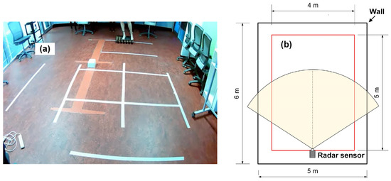
Figure 1.
(a) A photograph of the site and (b) a schematic of the room layout with the radar sensor range overlaid.
2.1.1. Stepper Motor Control System
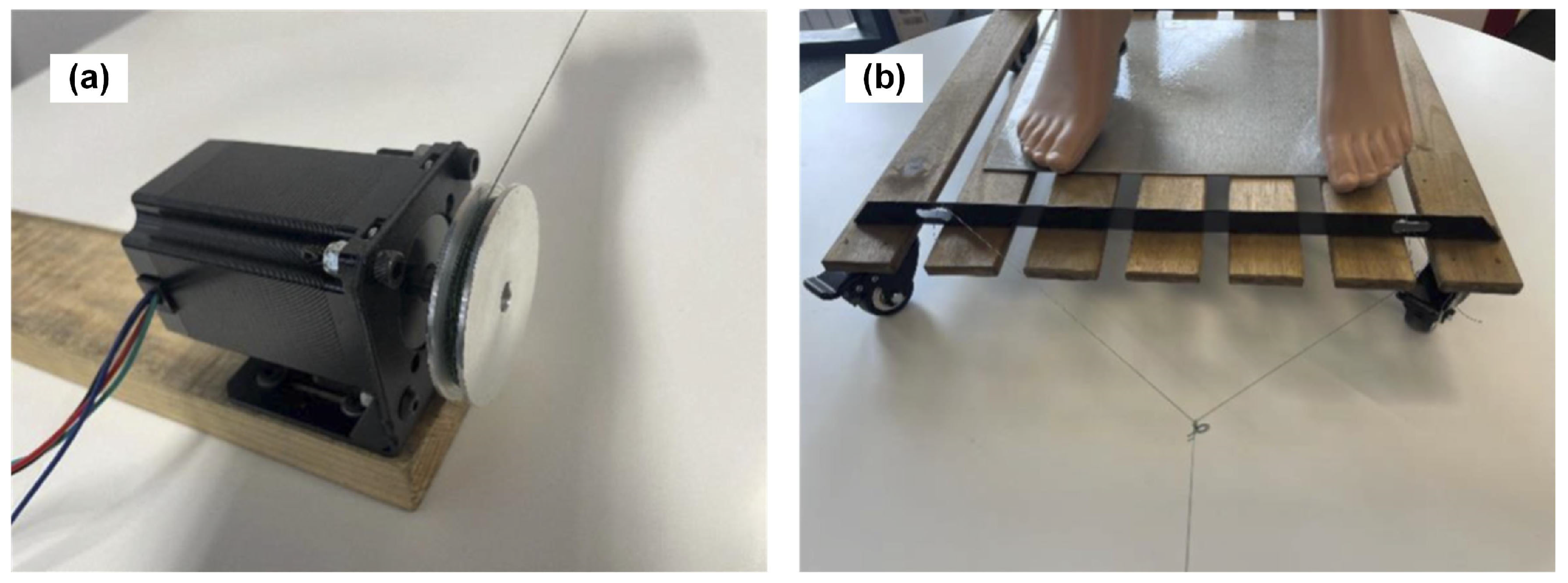
An in-house built pulley system, detailed in Figure 2, was coupled to a moving platform to manipulate the mounted mannequin. This control system utilises a pulley to move the mannequin and is composed of a stepper motor setup, which includes an Arduino controller, a TB6600 stepper motor driver (ELEGOO, Shenzhen, China), and a Nema 23 stepper motor (OMC Corporation Limited, Nanjing, China).
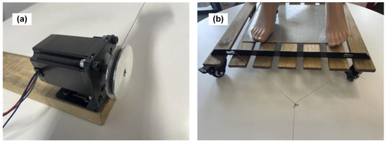
Figure 2.
The pulley control system comprising: (a) a motorised pulley, and (b) a movable platform on which the mannequin was mounted.
To select a motor and connection wire that can work with the planned load, the tensile force acting on the system was estimated. Based on the parameters of the pulley control system listed in Table 1, the experimental pulling force, denoted as , can be calculated using

Table 1.
Specificaitons of the pulley control system.
indicates the rolling resistance coefficient for the wheels of the moving platform. W represents the weight of the system. The safety factor for the connecting wire was ensured by limiting the pulling force to (75.46 N). The holding torque, = 0.05 N·m, was calculated considering the chosen pulley radius (50 mm) and the selected pulling force (1.01 N). Both the chosen connecting wire and stepper motor (holding torque: 2.4 N·m) satisfy the calculated force and torque requirements. For the purpose of this study, the system was operated with a platform moving speed of 0.5 m/s, comparable to the typical normal adult walking pace of 0.8 m/s to 1.2 m/s. Although the current platform’s movement speed is limited by the capacity of the testing stepper motor control system, the current setup is still valuable for testing purposes. This limitation does not preclude the use of a more powerful system in future iterations.
2.1.2. mmWave and Video Recording System
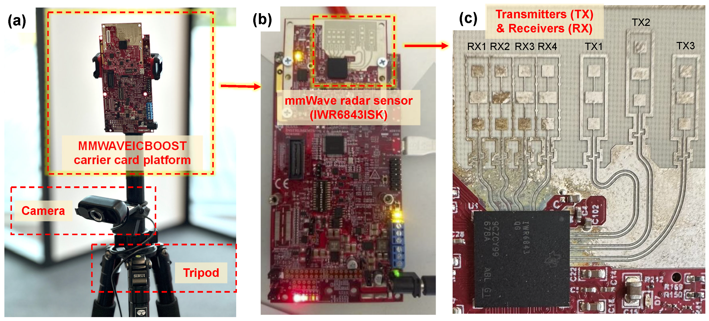
The measurement system comprises an IWR6843ISK radar sensor (Texas Instruments, Dallas, TX, USA), a ToLuLu Webcam HD 1080p camera (ToLuLu, Shenzhen, China) serving as ground truth reference, and a laptop control terminal for data collection, processing, and analysis. Figure 3a depicts the hardware setup. A synchronised Python script was developed to ensure the coordinated operation of the three subsystems: the mmWave radar sensor measurement system, the stepper motor control system, and the camera recording system.
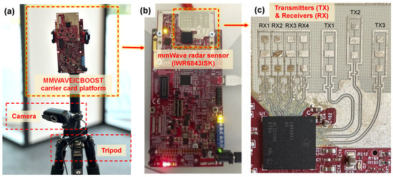
Figure 3.
The mmWave and video recording system used. (a) The overall hardware setup. (b) The mmWave radar sensor, and (c) The location of transmitters (TX) and receivers (RX) on the sensor.
The measurement system utilises an IWR6843ISK radar sensor [26], mounted on the MMWAVEICBOOST carrier card platform [27] as shown in Figure 3b. This single-chip frequency modulated continuous wave (FMCW) radar, developed by Texas Instruments (TI), facilitates data tracing and software development capabilities [14,28]. It captures information like range, angle, and Doppler shift from moving objects. In brief, the mmWave sensor operates by transmitting a chirp signal from transmitters (TX) within the 60 to 64 GHz range. Upon encountering a target, this signal is reflected and received by the receivers (RX). The received signal retains the characteristics of the original signal, but with a time delay. This time delay is dependent on the distance between the sensor and the target. Combining these signals generates an intermediate frequency (IF) signal containing raw data. As shown in Figure 3c, the system utilises three transmitters and four receivers. The carrier card platform processes the raw data and outputs a point cloud, providing information about the detected objects.
2.1.3. Experimental Scenarios and Procedures
This study aimed to achieve two key objectives. Firstly, it sought to demonstrate the feasibility of a platform in conjunction with an mmWave sensor for data generation. Secondly, the study aimed to leverage the platform’s functionality to enable systematic adjustments of system parameters and optimise sensor performance. This optimisation process is often challenging when using human subjects due to the difficulty of maintaining consistent speeds and trajectories. This novel platform, if proven effective, potentially addresses this challenge.
For this investigation, the height and angle of the sensor (as depicted in Figure 4) were varied. Heights ranged from 1.7 m to 2.1 m, while angles varied from 0° to 30°. The selection of the mannequin’s height (1.9 m) and sensor placement parameters (heights and angles) was guided by established practices in crowd detection sensor deployment. Since the test subject was a fixed-height mannequin (1.78 m mounted on a 0.12 m platform), the chosen sensor heights (1.7 m, 1.9 m, and 2.1 m) correspond to positions below, level with, and slightly above the mannequin’s top, respectively. This allows researchers to study how the relative position of the sensor and the subject affects the accuracy of the results. Similarly, the selection of tilt angles (0°, 15°, and 30°) facilitates the exploration of varying tilt angles on sensor performance. Common practice suggests positioning crowd detection sensors high enough to clear the top of tracked objects with a slight downward tilt to cover the desired area. However, a steeper down tilt can increase ground clutter noise, reducing the effective sensing area, while minimal or no tilt can decrease counting accuracy, particularly when individuals stand directly behind each other. By comparing the findings from this study on optimal sensor placement and configuration for improved crowd monitoring effectiveness with established practices, this research provides a form of validation for the platform’s ability to generate relevant data for algorithm development. As previously noted, the platform, to which the mannequin was mounted, moved at a speed of 0.5 m/s.

Figure 4.
Experimental scenarios with varied sensor (a) height and (b) angle.
The mmWave sensor operated in two modes during the mannequin’s movement assessment. The first method utilised two-dimensional (2D) data output from a polar coordinate system. In contrast, the second method employed three-dimensional (3D) data presented in a Cartesian coordinate format. The 2D data, processed with lower computational load, is expected to yield less process noise. Meanwhile, the 3D data has the potential to derive height information of the human subject. The 2D data mode is executed in the MATLAB environment and the 3D data mode is run in the Python environment. To ensure robustness and reliability, each scenario was conducted under identical conditions and repeated three times. This resulted in a total of 54 observations: 3 heights × 3 angles × 2 dimensions × 3 repetitions. The study provides valuable insights into the sensor system’s performance and adaptability across various scenarios.
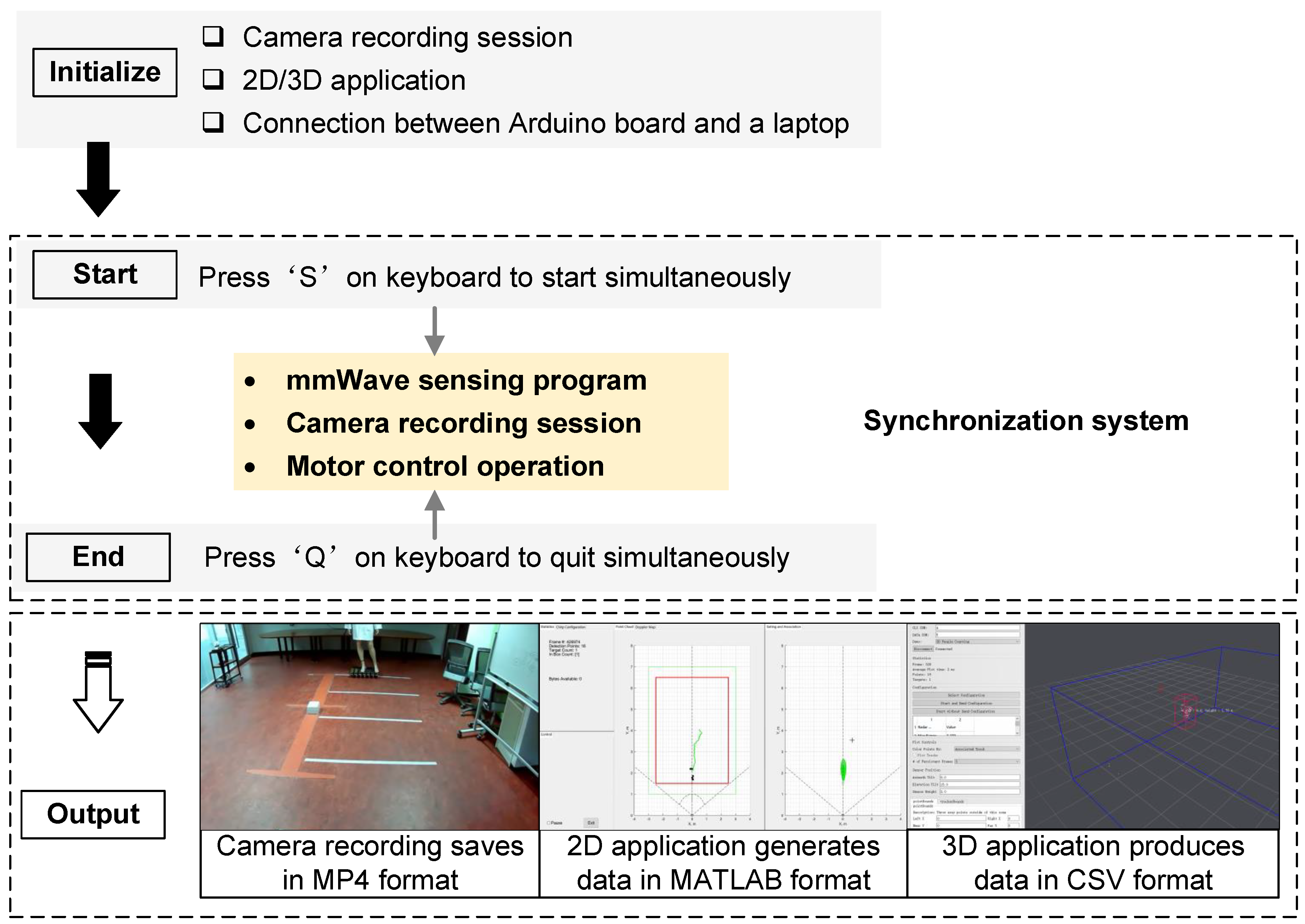
The experimental procedure involved the controlled movement of a mannequin mounted on a movable platform driven by a stepper motor system towards the mmWave sensor. The sensor and a camera simultaneously detected and recorded the mannequin’s motion. The camera data served as the ground truth reference for the experiment (Figure 5). The experiment began with essential preparations, including camera initialisation, configuration of the 2D/3D application, and establishing connection between the Arduino board and the laptop via the COM port. To ensure precise synchronisation among the mmWave sensing program, camera recording session, and motor control operation, a custom Python script facilitated a synchronised system. This system allowed the initiation and conclusion of the experiment with simple keyboard commands (“S” and “Q” keys, respectively).
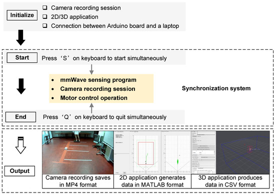
Figure 5.
The experimental procedures.
Following this controlled sequence, two separate file types were generated for subsequent analysis. The first file type contained human point cloud data stored in MATLAB (version: R2021b) format, specifically tailored for 2D applications. For 3D scenarios, the data was saved in a Comma-Separated Values (CSV) format. The second file type consisted of an MP4 video recording captured by the camera, providing visual recordings of the experiment.
2.2. Data Collection
Millimeter-wave (mmWave) sensors for people detection involve a sequential processing pipeline consisting of Front-End (FE), Low-Level, and High-Level stages. The FE processing stage encompasses both analog and digital components. The analog front-end transmits and receives signals, while the digital front-end employs a Frequency-Modulated Continuous Wave (FMCW) radar to generate complex Analog-to-Digital Converter (ADC) data, referred to as the beat signal. This beat signal serves as the raw input for the Low-Level processing stage.
In the Low-Level processing stage, the ADC samples containing chirp signals from each receiver–transmitter pair are processed. Range processing extracts target distances using the chirp time, while Doppler processing estimates target velocities by analysing the frequency shift of the return signal for each detected (range, azimuth) pair. This step often involves a Fast Fourier Transform (FFT) applied to the range domain data. To refine the data, static reflections (zero Doppler) are removed, and noise is reduced through filtering, improving the signal-to-noise ratio (SNR). By doing so, the specific range information for each chirp from each antenna is obtained, representing the location of certain points captured within the sensor’s field of view. The data collected from the number of chirps per antenna, the total number of antennas, and the detected range information are combined to create a radar data cube in a frame. This data cube forms the basis of the point cloud, where each point represents a target’s location (X, Y, and Z coordinates in 3D or X and Y in 2D) along with its radial velocity and SNR.
The High-Level processing stage leverages the point cloud data from Low-Level processing to identify, classify, and track people. By analysing the continuous stream of points frame-by-frame, statistical information can be extracted to differentiate between humans and stationary objects (ground clutter). The frame-by-frame analysis allows for tracking targets over multiple frames, enabling the computation of longer-term statistical measures.
For this study, only the outputs from the Low-Level processing stage is presented as the corresponding stage performs the initial signal processing tasks to extract crucial target information from the raw mmWave signal. This information, encapsulated in the point cloud, serves as the foundation for subsequent higher-level processing algorithms that can be used to identify, classify, and track people within the environment.
2.2.1. Camera Image Processing
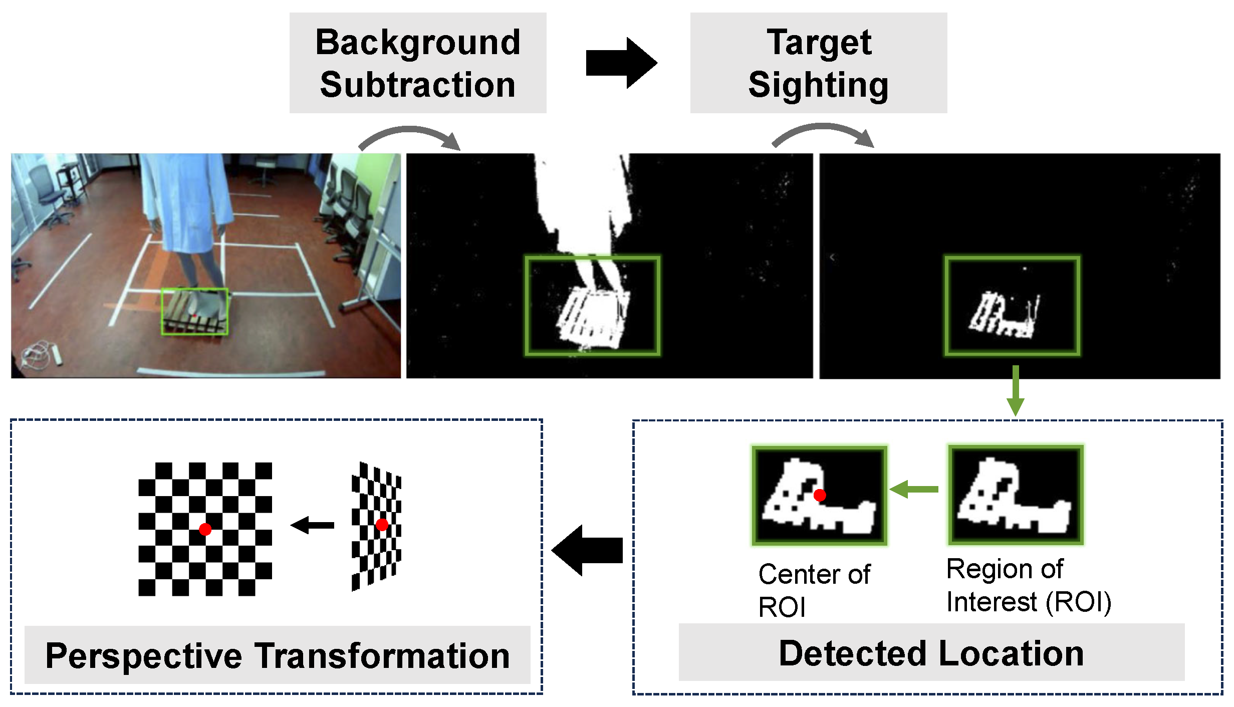
This research was conducted within a controlled indoor environment featuring consistent lighting to ensure stable experimental conditions. Figure 6 illustrates the process of detecting movement locations in the acquired images. Firstly, a background subtraction technique was employed. This involved subtracting a background image, acquired at the experiment’s start (without the mannequin and platforms), from subsequent images. This effectively filtered out the static background, isolating the foreground containing the moving objects.
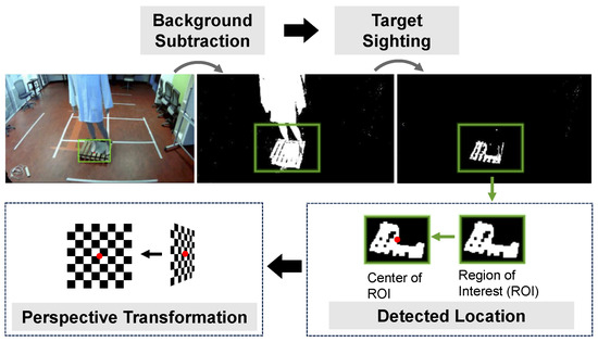
Figure 6.
The processing steps for detecting mannequin’s location in the image.
To derive a stable trajectory from the moving mannequin, the platform’s location was used as a reference point. An HSV (Hue, Saturation, Value) mask was applied to accurately extract the platform’s location in the image. Utilising an HSV mask provides certain advantages in handling lighting variations and minimising the impact of shadows. However, it is crucial to acknowledge that non-uniform lighting and colour similarity between the platform and its surroundings can still affect the accuracy of this approach. As shown in Figure 6, this method effectively separates the moving platform from the mannequin. The platform’s location was then determined by identifying the bounding box of the masked area and calculating its centre point. Finally, a perspective transformation [29] was applied to convert the image coordinates of the platform’s centre into actual location information for the point cloud figure. Once the platform’s trajectory was known, the mannequin’s trajectory was derived by aggregating the detected target locations throughout the experiment.
The trajectories obtained by a camera served as the ground reference in this research, conducted within a controlled indoor environment featuring a consistent light source, ensuring a static lighting condition. The study focused on a single moving target (the mannequin and platform), rendering the setup conducive to employing the background subtraction (BG subtraction) method in image processing.
3. Results
3.1. Validation
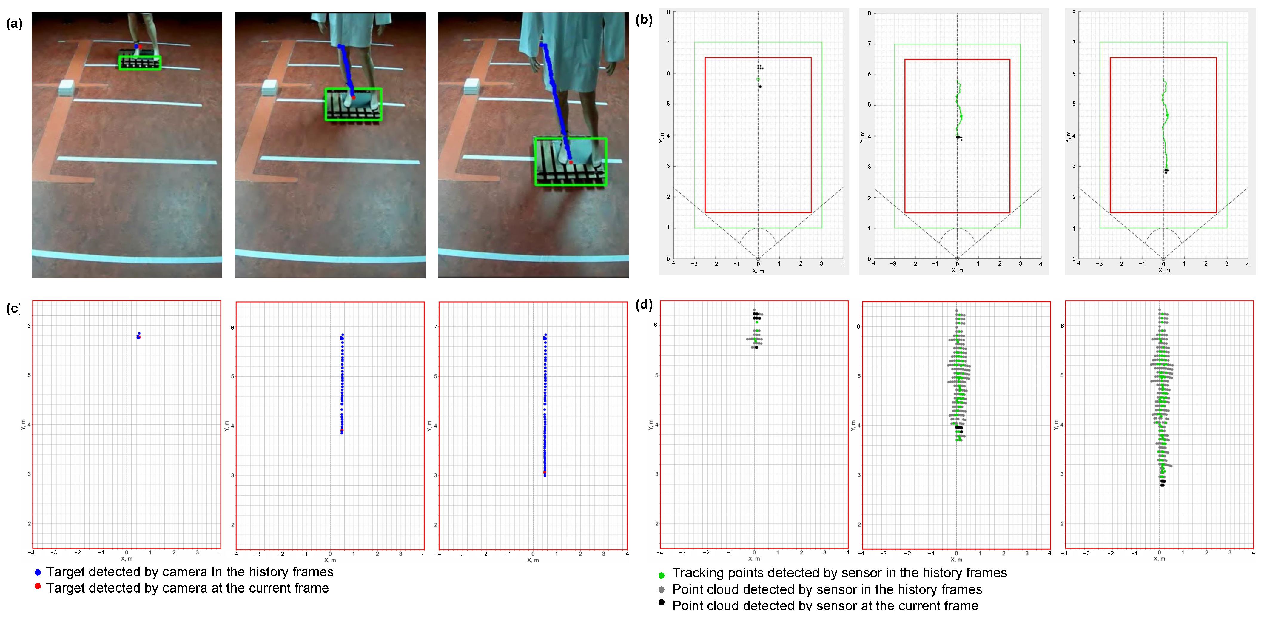
The experimental setup involved a mobile platform equipped with a life-size mannequin (Figure 7). The system utilised a stepper motor control mechanism (described in Section 2.1.1) to drive the dynamic movements of the mannequin. Specifically, the motor pulled the mannequin toward the mmWave sensor position. Simultaneously, a camera and mmWave sensor captured ground truth data and detected motion, respectively. Figure 7 illustrates various data outputs: (a) the selected image frames, (b) the corresponding 2D data, (c) the trajectory data derived from the camera image, and (d) the trajectory data from the mmWave sensor. These data collectively demonstrated for the first time the capability of the system to enable real-time monitoring and trajectory analysis of the proposed platform. Notably, during this feasibility study, the mannequin load was not perfectly centred on the platform. The pulley control system, driven by a motorised pulley, caused the platform to sway and exhibit lateral motion. Consequently, the mannequin shifted from side to side, as evident in the selected image frames. Importantly, this instability is also reflected in the presented 2D data. This validates the feasibility of using a movable platform with a life-size mannequin to simulate various scenarios. Furthermore, it demonstrates the system’s sensitivity in capturing motion variations.
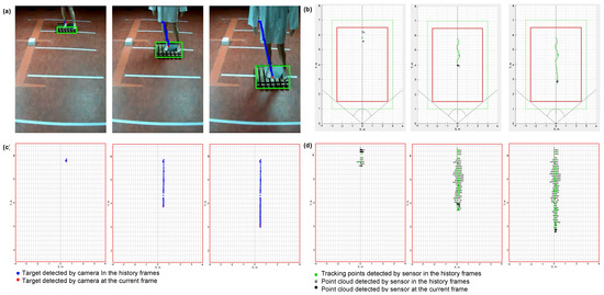
Figure 7.
(a) Sample image frames, (b) corresponding 2D data, (c) trajectory data derived from the camera image, and (d) trajectory data from the mmWave sensor. All data are captured by the data acquisition system as a life-size mannequin on a mobile platform was pulled towards it. The data acquisition system consisted of a camera and an mmWave sensor positioned at 1.9 m height and 0° angle relative to the mannequin. Floor markings were used to provide visual reference.
3.2. Optimisation
This section builds upon the established viability of the platform and explores its application for acquiring 2D and 3D data. Specifically, it aims to demonstrate its potential use to identify the optimal physical configuration for the sensor, specifically in terms of height and angle adjustments. Table 2 summarises the investigated scenarios, their settings, and corresponding notations for ease of references. For instance, a two-dimensional (2D) data scenario with a sensor height of 1.7 m and sensor angle of 0° is denoted as “2D/1.7/0”.

Table 2.
Summary of settings and corresponding notations for investigated scenarios.
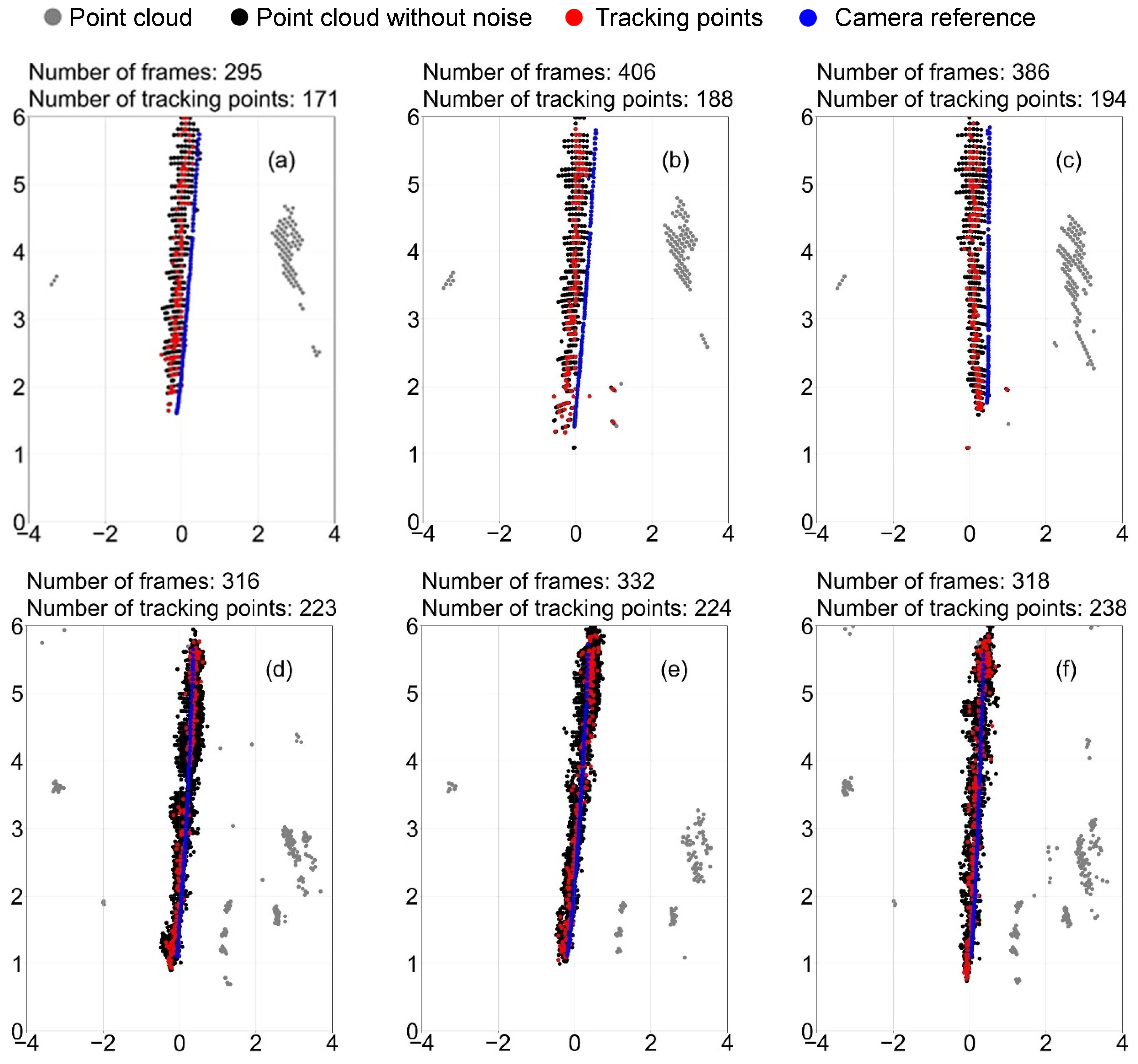
Figure 8 illustrates the trajectories of a moving mannequin captured under 2D/1.9/0 (panels (a)–(c)) and 3D/1.9/0 (panels (d)–(f)) detection scenarios, each repeated three times. The “number of frames” represents how many frames of point cloud data the sensor collected in the entire experiment. In the figures, the unprocessed point cloud visualises the raw sensor output of all frames, while the “point cloud without noise” refers to the point clouds after removing the extraneous data points that are located far from the region of interest. The “tracking points” are identified as the centroids of multiple noise-free points within each frame. The “number of tracking points” represents the total number of tracking points of all frames. The “camera reference” is derived by the video image, as detailed in Section 2.2.1.
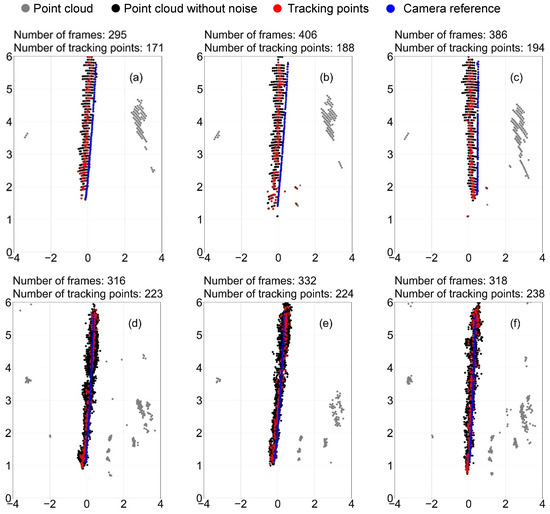
Figure 8.
Point cloud for tracking mannequin’s trajectories in the scenarios 2D/1.9/0: (a–c), and 3D/1.9/0: (d–f). Each experiment was repeated three times.
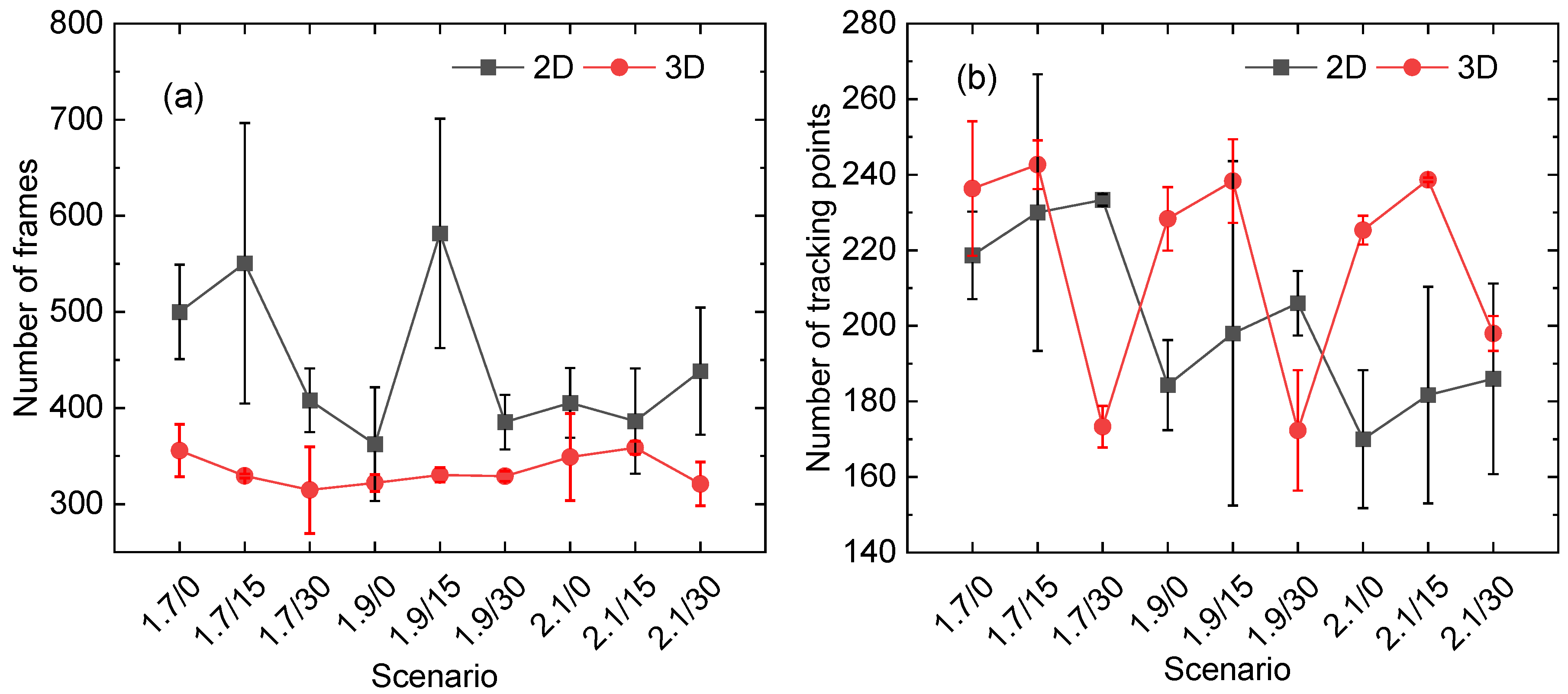
Figure 9 shows the number of frames and the tracking points across repetitions in all the scenarios. The values depicted in Figure 9a indicate that the 2D data acquisition method captures a larger number of frames over the same time period compared to the 3D method, although the values are closed in the cases 1.9/0 and 2.1/15. This suggests that the 2D method provides more detailed information with a lower computational burden. In terms of the number of tracking points, the 2D application typically produces fewer tracking points compared to the 3D application, with the exceptions being the cases 1.7/30 and 1.9/30. However, the subsequent section will focus on analysing the tracking accuracy, a crucial aspect in evaluating the effectiveness of the system.
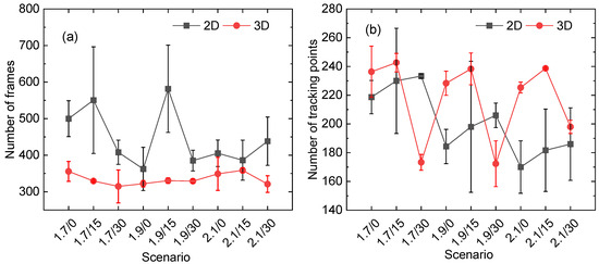
Figure 9.
The number of (a) frames and (b) tracking points across three repetitions in various scenarios.
3.3. Performance on Location Error
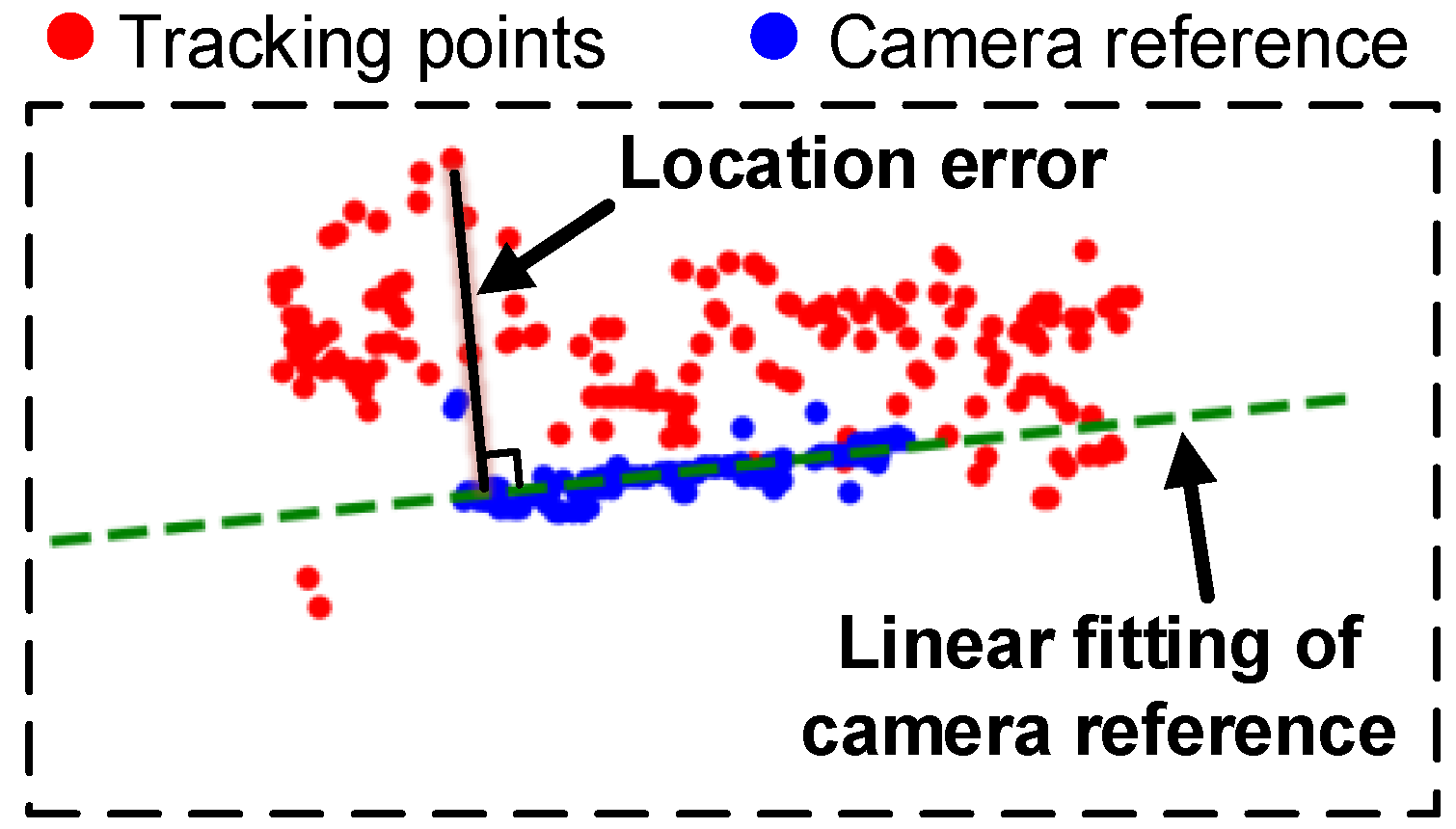
This section analyses the location error, quantifying the discrepancy between sensor-generated tracking points and camera-referenced points (Figure 10). The location error represents the distance between a tracking point and the linear fit of the camera reference line.
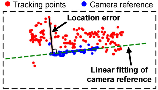
Figure 10.
The demonstration of how to obtain the location error.
A three-way analysis of variance (ANOVA) [30] was conducted to assess the influence of three factors on the location error across all test scenarios: sensor height, sensor angle, and data dimensionality (2D vs. 3D). ANOVA is a statistical test that examines the impact of independent variables (factors) on a continuous dependent variable, with significant effects indicated by p-values of less than a predetermined level. The p-value suggests the statistical significance of the observed differences between different groups (such as different sensor height). The significance level is defined as p-value < 0.01. The results in Table 3 reveal a statistically significant impact of all three factors and their interactions on the location error. Remarkably, the notable F-value suggests that data dimensionality is the most crucial factor, with sensor height closely following suit.

Table 3.
Three-way analysis of variance on the influence of factors at the location error (significance at p-value ). Bolded text indicates the most influential factor.
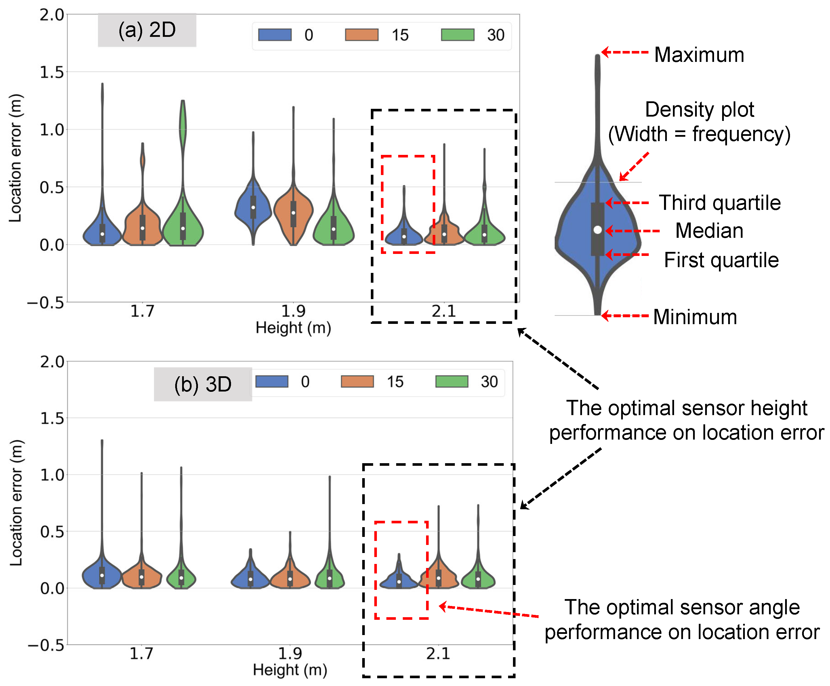
Figure 11 utilises violin plots to visually depict how sensor height, angle, and data dimensionality influence the distribution of location errors. Briefly, violin plots combine features of box plots and density plots, showcasing both the centre (interquartile range) and spread of the data while also revealing its overall distribution. Wider areas within the violin shape represent higher frequencies of data points at those values. As is evident from the figure, the optimal sensor configuration for minimising location error is achieved at a height of 2.1 m and an angle of 0°. Additionally, Table 4 also shows that the average location error for the 3D scenario is remarkable lower than that observed in 2D scenarios. The noteworthy performance at a height of 2.1 m suggests that positioning the sensor above the target and employing 3D data offer advantages for capturing the actual movement trajectory with greater accuracy.
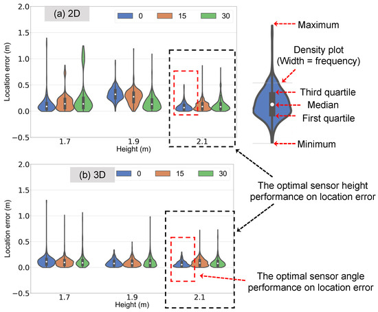
Figure 11.
The location error for the scenario with data collection of 2D: (a) and 3D: (b). The black dashed area indicates the optimal sensor height performance, specifically at 2.1 m, while the red dashed area highlights the best sensor angle performance, specifically at 0°.

Table 4.
Averaged location error (unit: m) without considering the influence of the sensor angle.
3.4. Performance on Height Error
mmWave radar sensor not only offers the ability to sense and track moving objects through reflections of electromagnetic waves, but also possess the capability to extract information about their height. This capability has garnered significant research interest in recent years due to its potential applications in various indoor environments. One area of particular interest is fall detection for elderly individuals living independently [31,32]. By monitoring changes in an individual’s height signature over time, mmWave sensors can potentially detect falls and trigger emergency alerts. This offers a non-invasive and privacy-preserving solution for monitoring elderly individuals in their homes, promoting independent living and timely assistance in case of emergencies. In the context of crowd evacuation scenarios, the ability to detect height variations using mmWave sensors can also be beneficial. During emergencies, rapid crowd movement can lead to congestion and bottlenecks, potentially increasing the risk of injuries and impeding efficient evacuation [33]. By measuring the height distribution within a crowd, mmWave sensors can provide valuable information to crowd management systems. For instance, identifying areas with a high concentration of individuals crouching or lying down could indicate potential hazards or blockages, enabling authorities to prioritise evacuation efforts in those areas [34].
To evaluate the effectiveness of mmWave sensors in detecting height variations, the experiment was performed using a mannequin with a known height (). The height error was determined by comparing the difference between the maximum and minimum z-coordinate locations detected by the sensor with the actual height of the mannequin (). The relative error, , is used to reflect the sensor’s accuracy in capturing height variations.
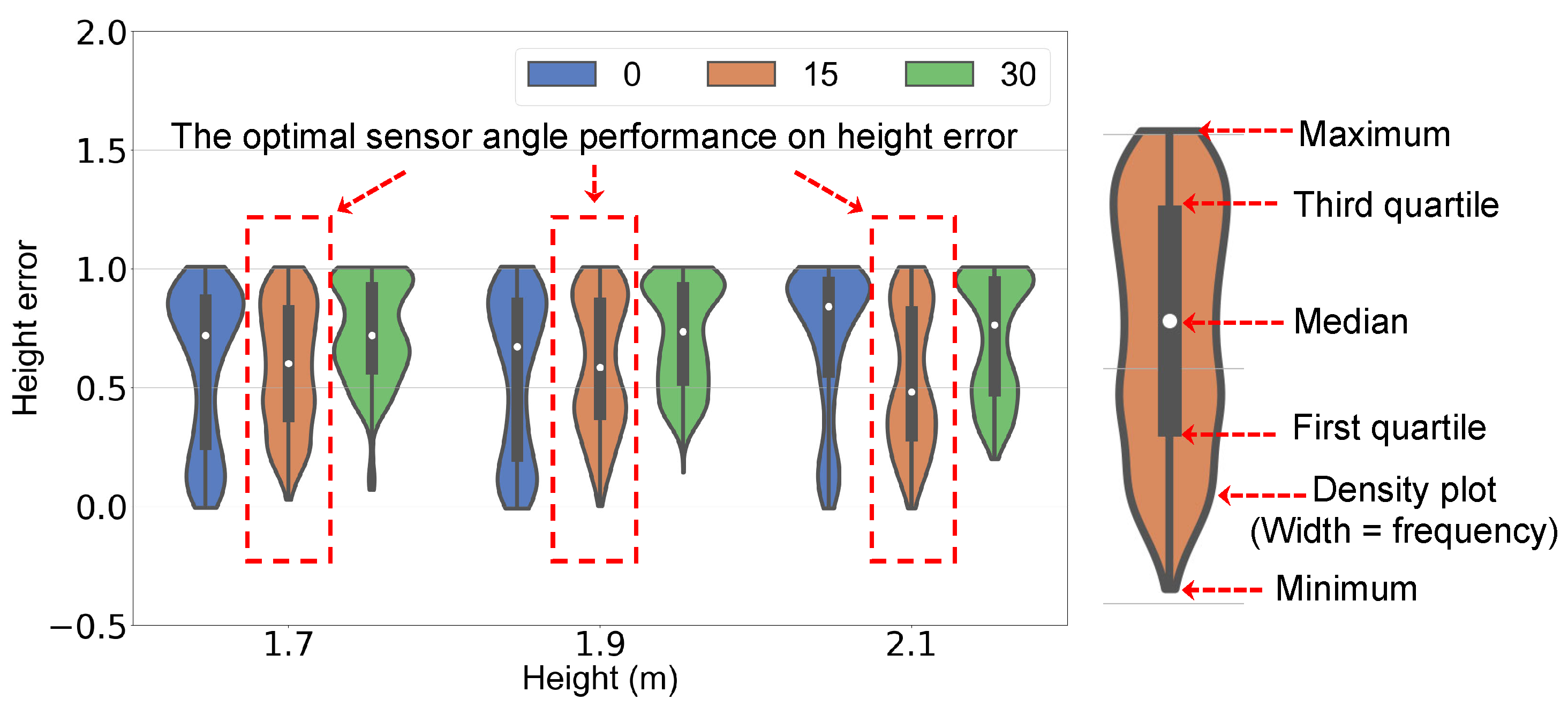
A two-way ANOVA was then performed to analyse the influence of sensor placement on the height error. The results, presented in Table 5, revealed that the angle of the sensor placement significantly affects the height error (p-value < 0.01), while the height of the sensor itself does not have a significant individual effect. However, the interaction between these two factors does play a notable role in determining the overall height error. Figure 12 visually depicts these findings, suggesting that an optimal sensor configuration for accurate height detection is achieved at an angle of 15°, which is approximately midpoint of the viable field-of-view of the mmWave radar.

Table 5.
Two-way analysis of variance on the influence of factors at the error of detecting height (Significance at p-value < 0.01). Bolded text indicates the most influential factor.
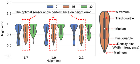
Figure 12.
The height error in different scenarios. The red dashed area indicates the optimal sensor angle performance, specifically at 15°.
4. Discussions
The development of mmWave radar sensors for indoor crowd motion sensing and tracking faces a significant bottleneck: the scarcity of large-scale, high-quality data for training and evaluation. Traditional approaches relying on human experiments present inherent difficulties [35,36]. Logistical complexities, ethical concerns, and safety issues are just some of the hurdles researchers encounter. Additionally, replicating precise movements with human subjects across repeated trials is highly challenging, introducing noise and variability into the data. This underscores the need for alternative methods capable of generating realistic and diverse data for mmWave radar development.
This paper proposes a potential approach to address the data gap: a movable platform equipped with a mannequin to generate data points for training and testing mmWave radar sensors. The platform offers the potential to simulate various crowd motions with diverse speed ranges and trajectories. This includes, for example, simulating walking, running, or crowds with varying densities. Additionally, the mannequin’s positioning can be customised to represent different human postures and orientations, such as standing, sitting, or crouching. Furthermore, the mmWave sensor setup can be configured in conjunction with the platform to simulate distinct sensor positioning scenarios. This includes varying the number of objects (people) being tracked, the distances between them, the angles of the sensor relative to the crowd, and the sensor’s resolution. These combined capabilities have the potential to generate a vast volume of data encompassing numerous parameters and scenarios, creating a rich and informative dataset.
Such a database would be invaluable for training and refining algorithms, ultimately leading to the development of more robust and accurate individual distinction capabilities. A major challenge in this domain is the difficulty in differentiating individuals within the collected mmWave sensor data due to the inherent ambiguity and limited resolution of the sensor readings. Clustering algorithms, commonly used to group similar data points (e.g., those representing individual people), often struggle with this task [37]. This limitation can lead to inaccurate crowd density estimations and hinder applications such as individual tracking and behaviour analysis. Beyond individual distinctions, the platform can be leveraged to investigate and address other algorithmic challenges associated with mmWave sensor usage in indoor environments. For example, the controlled setting it provides facilitates the study of sensor performance under various environmental conditions, such as the presence of obstacles. The obstacle factors are particularly relevant in indoor environments, where mmWave signals can reflect off walls and objects, leading to a phenomenon known as multipath propagation. This can create signal ghosting and distort the received data. By studying the platform’s performance in controlled multipath environments, researchers can develop algorithms that compensate for these effects. This information, in turn, can inform the development of algorithms with greater resilience to environmental factors, ultimately improving the overall robustness of the system in more diverse settings. The platform’s potential capacity to generate diverse and controlled data scenarios serves as a crucial tool for accelerating the development and refinement of mmWave sensor algorithms for numerous indoor crowd detection applications. It is important to acknowledge, however, that while this platform offers significant advantages for algorithm development and refinement, the algorithms developed and tested using this platform will ultimately require validation in real-world scenarios involving actual crowds to ensure their generalisability and robustness for practical crowd detection applications.
5. Conclusions
This study addressed a critical bottleneck in mmWave radar sensor development for indoor crowd motion sensing and tracking: the scarcity of high-quality, large-scale data for training and evaluation. Traditional approaches relying on human experiments face logistical complexities, ethical concerns, and safety issues. Additionally, replicating precise movements with human subjects across trials is challenging, introducing noise and variability into the data. This highlights the need for alternative methods to generate realistic and diverse data for mmWave radar development. This paper presents the first demonstration of a novel approach to address this data gap: a movable platform equipped with a life-size mannequin to generate data points for training and testing mmWave radars. The platform offers the potential to simulate various crowd motions, positions, and orientations. The study showcased the platform’s potential to optimise sensor placement relative to the target object—a task inherently challenging with human subjects due to the complexity of replicating precise movements. The preliminary optimisation results indicated that sensor angle, height, and data format all influence tracking performance. Notably, sensor height emerged as the most impactful factor, with an optimal height of 2.1 m (above the test subject) yielding the best results. The study also demonstrated that the 3D data format provides more accurate location information despite having fewer frames compared to the 2D format. Furthermore, exploration of using sensor 3D data to derive height distribution revealed that sensor angle significantly influences height error, with the optimal angle identified as 15° downwards from the horizontal plane.
This work represents the first step towards a platform capable of generating a vast volume of data encompassing numerous parameters and scenarios. This rich and informative dataset holds promise for enhancing the detection and categorisation capabilities of mmWave sensors for crowd evacuation monitoring applications.
Author Contributions
Conceptualisation, Y.Z., D.G. and Q.N.C.; methodology, S.X., G.Z. and Y.Z.; writing—original draft preparation, D.G.; writing—review and editing, Q.N.C., S.X., G.Z., C.W., W.W., S.H.L. and E.W.M.L.; funding acquisition, Q.N.C. and G.H.Y. All authors have read and agreed to the published version of the manuscript.
Funding
This research was funded by Australian Research Council (IC170100032) and Wuhan Shuanglian-Xingxin Machinery and Equipments, China.
Institutional Review Board Statement
Not applicable.
Informed Consent Statement
Not applicable.
Data Availability Statement
The data presented in this study are available upon request from the corresponding author.
Conflicts of Interest
The authors declare no conflicts of interest.
References
- Liu, X.; Zhang, H.; Zhu, Q. Factor analysis of high-rise building fires reasons and fire protection measures. Procedia Eng. 2012, 45, 643–648. [Google Scholar] [CrossRef]
- Li, G.Q.; Zhang, C.; Jiang, J. A review on fire safety engineering: Key issues for high-rise buildings. Int. J. High-Rise Build. 2018, 7, 265–285. [Google Scholar]
- Ronchi, E.; Nilsson, D. Fire evacuation in high-rise buildings: A review of human behaviour and modelling research. Fire Sci. Rev. 2013, 2, 1–21. [Google Scholar] [CrossRef]
- Morales, A.; Alcarria, R.; Martin, D.; Robles, T. Enhancing evacuation plans with a situation awareness system based on end-user knowledge provision. Sensors 2014, 14, 11153–11178. [Google Scholar] [CrossRef]
- US Fire Administration. Civilian Fire Injuries in Residential Buildings (2013–2015); Technical Report, Topical Fire Report Series; US Fire Administration: Frederick County, MD, USA, 2017.
- Galea, E.; Xie, H.; Deere, S.; Cooney, D.; Filippidis, L. An international survey and full-scale evacuation trial demonstrating the effectiveness of the active dynamic signage system concept. Fire Mater. 2017, 41, 493–513. [Google Scholar] [CrossRef]
- Xiong, Q.; Zhu, Q.; Du, Z.; Zhu, X.; Zhang, Y.; Niu, L.; Li, Y.; Zhou, Y. A dynamic indoor field model for emergency evacuation simulation. ISPRS Int. J. Geo-Inf. 2017, 6, 104. [Google Scholar] [CrossRef]
- Monaci, G.; Pandharipande, A.V. Passive Infrared Sensor System for Position Detection. US Patent 10,209,124, 19 February 2019. [Google Scholar]
- Yu, K.M.; Yu, C.S.; Lien, C.C.; Cheng, S.T.; Lei, M.Y.; Hsu, H.P.; Tsai, N. Intelligent evacuation system integrated with image recognition technology. In Proceedings of the 2015 8th International Conference on Ubi-Media Computing (UMEDIA), Colombo, Sri Lanka, 24–26 August 2015; pp. 23–28. [Google Scholar]
- Wang, W.; Liu, A.X.; Shahzad, M. Gait recognition using wifi signals. In Proceedings of the 2016 ACM International Joint Conference on Pervasive and Ubiquitous Computing, Heidelberg, Germany, 12–16 September 2016; pp. 363–373. [Google Scholar]
- Kastek, M.; Madura, H.; Sosnowski, T. Passive infrared detector for security systems design, algorithm of people detection and field tests result. Int. J. Saf. Secur. Eng. 2013, 3, 10–23. [Google Scholar] [CrossRef]
- Zou, H.; Zhou, Y.; Yang, J.; Gu, W.; Xie, L.; Spanos, C. Wifi-based human identification via convex tensor shapelet learning. In Proceedings of the AAAI Conference on Artificial Intelligence, New Orleans, LA, USA, 2–7 February 2018; Volume 32. [Google Scholar]
- Huang, X.; Cheena, H.; Thomas, A.; Tsoi, J.K. Indoor detection and tracking of people using mmwave sensor. J. Sens. 2021, 2021, 1–14. [Google Scholar] [CrossRef]
- Livshitz, M. Tracking Radar Targets with Multiple Reflection Points; TI Internal Document; Texas Instruments: Dallas, TX, USA, 2017. [Google Scholar]
- Zhao, P.; Lu, C.X.; Wang, J.; Chen, C.; Wang, W.; Trigoni, N.; Markham, A. Human tracking and identification through a millimeter wave radar. Ad Hoc Netw. 2021, 116, 102475. [Google Scholar] [CrossRef]
- Ferris, D.D., Jr.; Currie, N.C. Microwave and millimeter-wave systems for wall penetration. In Proceedings of the Targets and Backgrounds: Characterization and Representation IV, Orlando, FL, USA, 13–17 April 1998; Volume 3375, pp. 269–279. [Google Scholar]
- Lee, S.P.; Kini, N.P.; Peng, W.H.; Ma, C.W.; Hwang, J.N. Hupr: A benchmark for human pose estimation using millimeter wave radar. In Proceedings of the IEEE/CVF Winter Conference on Applications of Computer Vision, Waikoloa, HI, USA, 2–7 January 2023; pp. 5715–5724. [Google Scholar]
- Yan, B.; Wang, P.; Du, L.; Chen, X.; Fang, Z.; Wu, Y. mmGesture: Semi-supervised gesture recognition system using mmWave radar. Expert Syst. Appl. 2023, 213, 119042. [Google Scholar] [CrossRef]
- Yang, Y.; Xu, H.; Chen, Q.; Cao, J.; Wang, Y. Multi-vib: Precise multi-point vibration monitoring using mmwave radar. Proc. ACM Interact. Mob. Wearable Ubiquitous Technol. 2023, 6, 1–26. [Google Scholar] [CrossRef]
- Zeng, S.; Wan, H.; Shi, S.; Wang, W. mSilent: Towards general corpus silent speech recognition using COTS mmWave radar. Proc. ACM Interact. Mob. Wearable Ubiquitous Technol. 2023, 7, 1–28. [Google Scholar] [CrossRef]
- Bystrov, A.; Daniel, L.; Hoare, E.; Norouzian, F.; Cherniakov, M.; Gashinova, M. Experimental evaluation of 79 and 300 GHz radar performance in fire environments. Sensors 2021, 21, 439. [Google Scholar] [CrossRef] [PubMed]
- Krüll, W.; Tobera, R.; Willms, I.; Essen, H.; Von Wahl, N. Early forest fire detection and verification using optical smoke, gas and microwave sensors. Procedia Eng. 2012, 45, 584–594. [Google Scholar] [CrossRef]
- Li, S.; Hishiyama, R. An Indoor People Counting and Tracking System using mmWave sensor and sub-sensors. IFAC-PapersOnLine 2023, 56, 7096–7101. [Google Scholar] [CrossRef]
- Huang, X.; Patel, N.; Tsoi, K.P. Application of mmWave Radar Sensor for People Identification and Classification. Sensors 2023, 23, 3873. [Google Scholar] [CrossRef] [PubMed]
- Fonollosa, J.; Solórzano, A.; Marco, S. Chemical sensor systems and associated algorithms for fire detection: A review. Sensors 2018, 18, 553. [Google Scholar] [CrossRef] [PubMed]
- TI Incorporeted. IWR6843ISK: IWR6843 Evaluation Module for Single-Chip 60 GHz Long-Range Antenna mmWave Sensor; Texas Instruments: Dallas, TX, USA, 2024. [Google Scholar]
- TI Incorporeted. MMWAVEICBOOST: mmWave Sensors Carrier Card Platform; Texas Instruments: Dallas, TX, USA, 2024. [Google Scholar]
- Garcia, K. Bringing intelligent autonomy to fine motion detection and people counting with TImmWave sensors. Tex. Instrum. 2018, 1, 1–9. [Google Scholar]
- Mezirow, J. Perspective transformation. Adult Educ. 1978, 28, 100–110. [Google Scholar] [CrossRef]
- St, L.; Wold, S. Analysis of variance (ANOVA). Chemom. Intell. Lab. Syst. 1989, 6, 259–272. [Google Scholar]
- Wang, B.; Guo, L.; Zhang, H.; Guo, Y.X. A millimetre-wave radar-based fall detection method using line kernel convolutional neural network. IEEE Sens. J. 2020, 20, 13364–13370. [Google Scholar] [CrossRef]
- Rezaei, A.; Mascheroni, A.; Stevens, M.C.; Argha, R.; Papandrea, M.; Puiatti, A.; Lovell, N.H. Unobtrusive human fall detection system using mmwave radar and data driven methods. IEEE Sens. J. 2023, 23, 7968–7976. [Google Scholar] [CrossRef]
- Helbing, D.; Johansson, A.; Al-Abideen, H.Z. Dynamics of crowd disasters: An empirical study. Phys. Rev. E 2007, 75, 046109. [Google Scholar] [CrossRef] [PubMed]
- Ibrahim, A.M.; Venkat, I.; Subramanian, K.; Khader, A.T.; Wilde, P.D. Intelligent evacuation management systems: A review. ACM Trans. Intell. Syst. Technol. 2016, 7, 1–27. [Google Scholar] [CrossRef]
- Gu, T.; Fang, Z.; Yang, Z.; Hu, P.; Mohapatra, P. Mmsense: Multi-person detection and identification via mmwave sensing. In Proceedings of the 3rd ACM Workshop on Millimeter-Wave Networks and Sensing Systems, Los Cabos, Mexico, 21–25 October 2019; pp. 45–50. [Google Scholar]
- Zhang, J.; Xi, R.; He, Y.; Sun, Y.; Guo, X.; Wang, W.; Na, X.; Liu, Y.; Shi, Z.; Gu, T. A survey of mmWave-based human sensing: Technology, platforms and applications. IEEE Commun. Surv. Tutor. 2023, 25, 2052–2087. [Google Scholar] [CrossRef]
- Pegoraro, J.; Meneghello, F.; Rossi, M. Multiperson continuous tracking and identification from mm-wave micro-Doppler signatures. IEEE Trans. Geosci. Remote Sens. 2020, 59, 2994–3009. [Google Scholar] [CrossRef]
Disclaimer/Publisher’s Note: The statements, opinions and data contained in all publications are solely those of the individual author(s) and contributor(s) and not of MDPI and/or the editor(s). MDPI and/or the editor(s) disclaim responsibility for any injury to people or property resulting from any ideas, methods, instructions or products referred to in the content. |
© 2024 by the authors. Licensee MDPI, Basel, Switzerland. This article is an open access article distributed under the terms and conditions of the Creative Commons Attribution (CC BY) license (https://creativecommons.org/licenses/by/4.0/).

