Article

Experimental Investigation and Theoretical Analysis of Flame Spread Dynamics over Discrete Thermally Thin Fuels with Various Inclination Angles and Gap Sizes

1
College of Urban Construction and Safety Engineering, Shanghai Institute of Technology, Shanghai 201418, China
2
Sino-German College of Intelligent Manufacturing, Shenzhen Technology University, Shenzhen 518118, China
3
Shenzhen Research Institute, China University of Mining and Technology, Shenzhen 518055, China
*
Authors to whom correspondence should be addressed.
Fire 2024, 7(6), 177; https://doi.org/10.3390/fire7060177
Submission received: 16 April 2024 / Revised: 15 May 2024 / Accepted: 20 May 2024 / Published: 23 May 2024

Abstract

:
Flame spread over discrete fuels is a typical phenomenon in fire scenes. Experimental and theoretical research on flame spread over discrete thermally thin fuels separated by air gaps with different inclination angles was conducted in the present study. Experiments with six inclination angles ranging from 0° to 85° and various fuel coverage rates from 0.421 to 1 were designed. The flame spread behavior, the characteristic flame size, and the flame spread rate were analyzed. The results show that the flow pattern, stability, and flame size exhibit different characteristics with different inclination angles and gap sizes. As the inclination angle increases, particularly with smaller gaps, turbulent and oscillating flames are observed, while larger gap sizes promote flame stability. The mechanism of flame propagation across the gap depends on the interplay between the flame jump effect and heat transfer, which evolves with gap size. Average flame height, average flame width, and flame spread rate initially increase and then decline with the increase in fuel coverage, peaking at fuel coverage rates between 0.93 and 0.571 for different inclination angles. A theoretical model is proposed to predict the flame spread rate and the variation in the flame spread rate with inclination angle and fuel coverage. Furthermore, the map determined by inclination angle and fuel coverage is partitioned into distinct regions, comprising the accelerated flame spread region, the flame spread weakening region, and the failed flame spread region. These findings provide valuable insights into flame spread dynamics over discrete thermally thin fuels under diverse conditions.

1. Introduction

Fire dynamics and its prevention strategies have long been a key topic of in-depth research and ongoing interest for fire protection personnel [1]. For example, flame spread over discrete solid fuel is a common phenomenon in various fire scenarios, including warehouse shelf fires, wildland fires, and high-rise building balcony fires, garnering increasing attention within the scientific community. Discrete fuel configurations consist of multiple fuel segments separated by inert materials or air gaps, often representing a more realistic fire load in practical fire scenarios compared with continuous solid fuel combustion. For instance, in the context of a warehouse fire, flames can swiftly traverse between stored commodities through vertical or horizontal gaps in the shelving system, giving rise to a three-dimensional fire of significant scale. In the scene of wildland fires, flame propagation over discrete biomass fuels consistently involves the transition of flames from one element to the succeeding element [2]. These gaps effectively serve as barriers between combustible materials, reducing the likelihood of flame spread [3]. However, recent research has indicated that under certain conditions, such as increased separation distances between fuel elements [4,5] or decreased fuel coverage rates [6], flames can propagate more rapidly over discrete fuels compared with continuous ones. In these fire scenarios, the inclination angle of the fuel has a significant impact on flame spread. Wildland fires are often characterized by sloped terrain, while racks and the exterior facades of balconies are typically oriented vertically upward. Consequently, discrete solid combustibles at different inclination angles may pose a heightened fire safety risk compared with their continuous counterparts. Systematically conducting in-depth investigations into flame spread behavior over discrete combustible materials with various inclinations is of paramount importance for advancing fire safety design and regulations.
The phenomenon of flame propagation across solid surfaces has been the subject of extensive research over the years, resulting in an extensive body of literature on the topic. Fernandez et al. [6] delved into the mechanisms of laminar flame spread over flat PMMA surfaces in different orientations, proposing a theoretical model that emphasizes solid heat conduction and the thermal runaway of gas-phase ignition reactions. R.J. Santoro [7] explored the mechanism of flame spread, offering fundamental insights into the governing principles of the process. By combining experimental studies with theoretical analyses, R.S. Magee [8] revealed the underlying mechanisms behind flame propagation on solid surfaces. Additionally, other authors [9,10,11] have conducted a detailed examination of dominant heat transfer mechanisms in flame spread through experimental and theoretical analyses. These studies have specifically proposed theoretical models addressing continuous flame spread over thermally thick fuels. For the discrete fuel configuration proposed in this study, the flame spread characteristics in discrete scenarios may diverge from those observed in continuous flame spread. Hence, investigating whether classical flame spread models proposed by previous researchers align with discrete flame spread is a subject worthy of exploration. Investigating flame spread on discrete fuels requires the consideration of factors such as the geometric shape of the fuel. This is essential to enhancing the applicability of research findings to practical fire protection engineering.
A substantial body of literature places particular emphasis on the phenomenon of flame spread over matrices of spaced matchsticks (without heads) [4,12,13,14,15,16,17,18,19]. Notably, M. Vogel and F. A. Williams [12] developed a comprehensive theoretical thermal model, integrating their experimental data, which revealed the pivotal role of convective heat transfer in driving flame propagation over these matchstick arrays. Further insights into upward flame propagation were gained by Gollner et al. [4], who investigated horizontally oriented match rods affixed to a vertical steel wall. Their findings demonstrated that both the flame spread rate and the rate of sample mass loss increased in correlation with greater spacing between the match rods. Meanwhile, Finney et al. [13] conducted a series of laboratory experiments involving artificial fuel beds where they controlled the structural characteristics of gaps, their depth, and the slope of the surface. The results uncovered that fire spread was constrained by the gap distance, with fuel particles across the gap igniting only upon direct contact with the flame. Numerous researchers have delved into the phenomenon of discrete solid flame spread, examining various variables, such as applied ambient wind speed, wood size, fuel element height, fuel bed tilt angle, and fuel moisture content [14,15,16,17,18,19]. These investigations consistently indicate that flame spread is more likely to occur in deeper fuel beds [14,15], at higher wind speeds [14,16,17], and on steeper fuel bed surfaces [18,19].
In addition to examining matrix fuel arrangements, several studies have explored flame propagation over discrete solid materials in the form of flat plates. Y. Watanabe et al. [2] presented findings on the flame spread rate with respect to fuel load over paper samples featuring randomly distributed pores, revealing a non-monotonic trend. Gollner and Miller [4] conducted experiments to investigate flame spread over vertical PMMA blocks separated by insulation. Their study revealed a maximum flame spread rate occurring at f = 0.67, possibly attributable to a delayed thickening of the boundary layer or increased air entrainment. Park et al. [20] conducted numerical investigations into flame spread phenomena for discrete thermally thin solids. Their model illustrated a non-linear impact of air gaps on the burning rate. Cui and Liao [21] performed experimental studies on upward flame spread over discrete combustibles separated by air gaps. Their results demonstrated a non-monotonic relationship between the flame spread rate and burning rate with respect to gap size. Luo et al. [22] explored the effect of gap size between discrete fuels on opposed flame spread. Their findings reveal that heat transfer from the flame to the discrete fuel decreased as the gap size increased. Furthermore, Z. Wang et al. [23] conducted experimental research on various characteristics of upward flame spread, including flame rate, shape, height, temperature field, and heat transfer behavior over discrete XPS materials. Their study aimed to uncover the mechanisms behind the influence of fuel coverage on flame spread behavior.
It is worth noting that prior experiments on discrete solid materials have predominantly focused on vertically upward flame spread. However, there has been relatively limited research on the flame spread behavior of discrete fuels in inclined configurations. Notable contributions in this direction include studies by Gollner [15], Xie [18], and An [24], each of which investigated discrete flame spread experiments at various inclination angles. Gollner et al. [15] explored inclined flame spread on PMMA samples, a departure from typical studies that focused on vertical flame propagation. Surprisingly, they discovered that the flame spread rate in the vertical direction was moderately faster at the bottom of PMMA than in conventional vertical upward flame spread scenarios. An et al. [24] delved into upward flame spread over discrete XPS materials separated by air gaps, examining a range of inclination angles (α = 60°, 75°, 90°, 105°, 120°, and 135°). Their findings indicate that flame spread rate and melt zone length both decreased as the inclination angle increased. In addition, Xie [18] and Beer [25] developed critical flame spread models, although previous studies on the impact of inclination angles have primarily centered around thermally thick materials. Typically, solid fuels were affixed to insulated back plates to mitigate the effects of backside heat transfer. However, further investigation is required to comprehend flame spread characteristics over discrete thermally thin materials in inclined configurations.
The literature review reveals that previous studies have predominantly centered on discrete fuels in both vertical [18,22,23,26] and horizontal [23,27,28] configurations. However, research on the influence of space distance on discrete flame spread over inclined solid fuels, particularly thermally thin materials, remains relatively limited. In this paper, a comprehensive series of experiments were conducted to investigate flame spread over discrete thermally thin cellulosic materials, considering the combined effects of air gap size and inclination angle. The primary objective of this study is to empirically analyze crucial parameters, including flame spread rate, typical flame phenomena, flame height, flame width, and the influence mechanism of fuel coverage on flame spread behavior.

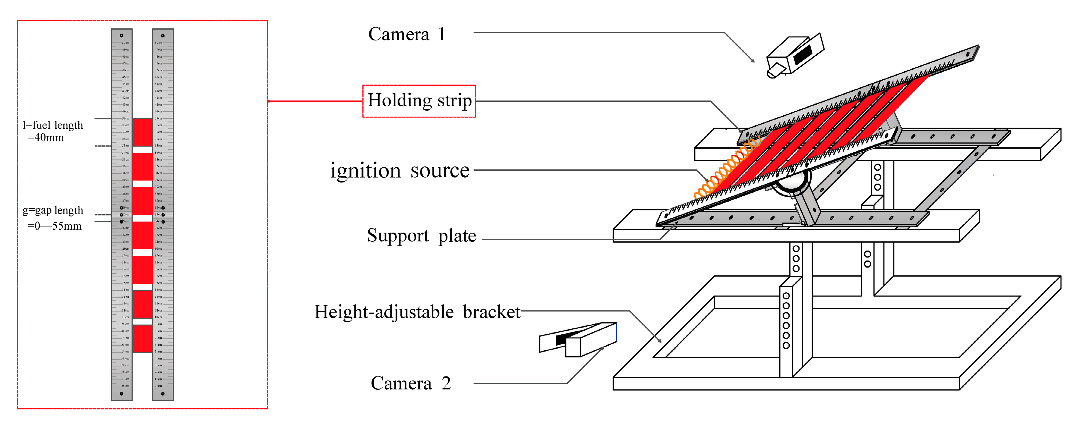
2. Materials and Methods

The experimental platform, depicted in Figure 1, has been specifically designed to investigate the discrete flame spread characteristics over thermally thin paper. This apparatus comprises a rotatable holder and two video recorders for data collection. The rotatable holder, constructed from stainless steel, allows for the setting of different tilt angles. The sample is securely held between two stainless steel plates, with bolts available for adjustments to eliminate any air gap between these plates. In practical fire scenarios, concurrent flame propagation poses a considerable danger due to the rapid spread of flames and warrants thorough investigation. A low inclination of the fuel can result in flame separation from the fuel surface, whereas an elevated inclination angle can induce flame adherence to the fuel surface, thereby altering the heat transfer dynamics of the flame [8]. We selected experimental parameters encompassing a spectrum from horizontal to nearly vertical orientations, meticulously specifying inclination angles of 0°, 5°, 25°, 45°, 65°, and 85°. Moreover, one of the plates features an engraved scale to facilitate the calibration of characteristic flame size during the flame spread process. Two video recorders, recording at a rate of 25 frames per second, were employed to capture the flame spread process. Subsequently, data on flame shape, characteristic flame lengths, and flame spread rate were extracted from the processed video images. The characteristic flame lengths include flame height ( h f ) and flame width ( w f ), as shown in Figure 2. Flame height is defined as the vertical distance from the bottom to the tip of the flame. Flame width is defined as the length of the flame that is closely attached to the surface of the sample.
For the present study, thermally thin paper samples were employed. Seven cellulose paper samples, each measuring 40 mm × 40 mm × 0.274 mm (length × width × thickness), were securely fixed within the sample holder. The value of Biot number ( B i = τ · h λ , where τ , λ , and h represent the sample thickness, the thermal conductivity of the sample, and the heat transfer coefficient of air) for the material used in this study was calculated as 0.088, significantly less than 0.1, indicating that the material with a thickness of 0.274 mm was considered thermally thin in this study. The effective exposed sample width was 30 mm due to the secure fixation of the sample ends by stainless steel plates. To create separation between the adjacent cellulose paper samples, various air gap distances, defined as gap length (g) and illustrated in Figure 1, were set. Prior to conducting the experiments, the samples underwent a 10 h drying process in a drying oven set to an ambient temperature of 100 °C to eliminate any moisture-related effects. To characterize the interplay between fuel length and gap size, a dimensionless parameter known as fuel coverage (f) was used. Fuel coverage, denoted as f, can be calculated by using the formula f = l / g + l , where l represents the fuel length, as shown in Figure 1 [23]. Our objective is to explore the impact of spacing on the progression of flame spread from continuous to critical conditions. To achieve this, we chose distinct fuel coverage rates, ranging from 1 to the critical fuel coverage rate, across different angles. Table 1 provides an overview of the experimental configurations employed in this study.
In this study, the sample ignition process was executed by using a linear ignition source composed of a nichrome coil heater. A constant flow source, operating at a fixed current of 5.9 A, was used to supply consistent electrical power for the ignition process. Once the sample edge was successfully ignited, the ignition source was promptly removed. To ensure the capture of high-quality images depicting flame spread and to minimize potential disturbances, all experiments were conducted within a controlled, darkened environment. Additionally, each experiment was meticulously repeated 3–4 times to ensure the repeatability and reliability of the experimental data. During the data processing of the present study, the data in the real time images are derived from one set of experimental results from repeated experiments. The values in the scatter diagrams represent the mean values obtained from 3–4 independent repetitions. The error bars represent the standard deviation of these repetitions.

3. Results and Discussion

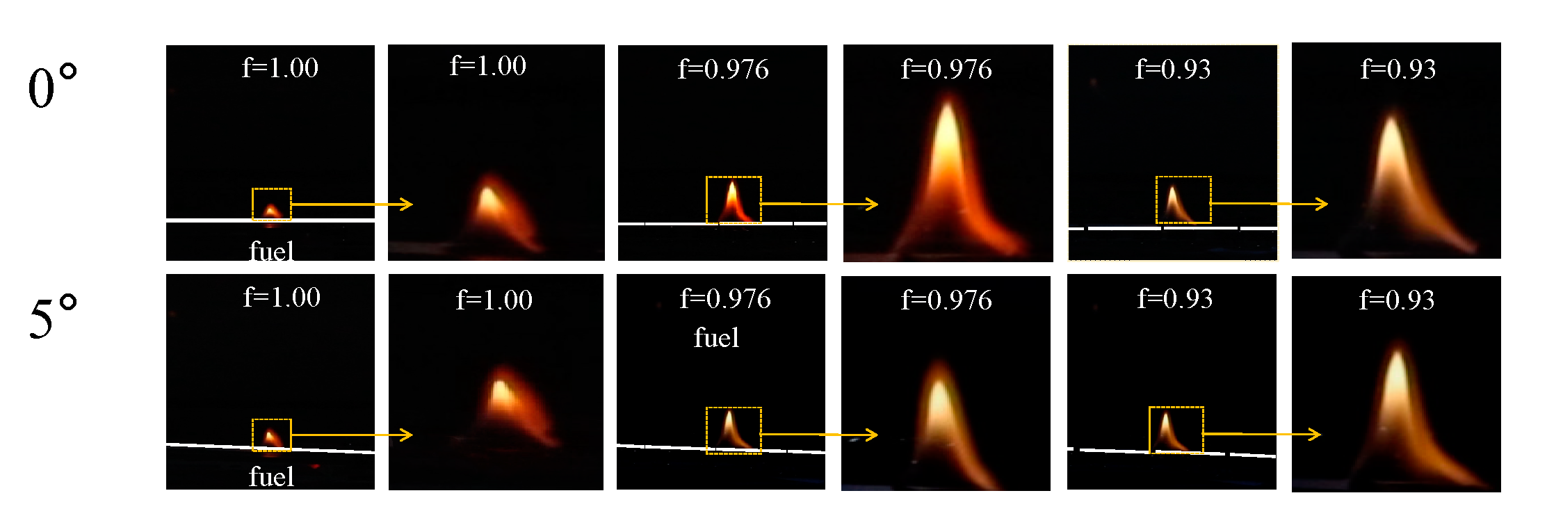
3.1. Flame Spread Behavior Characterization

A series of typical flame spread images during flame spread with different fuel coverage rates and inclination angles are presented in Figure 3 and Figure 4, which show that the flames exhibited obvious differences. Unlike with continuous fuel, the flames of discrete fuel need to cross gaps to ignite the virgin fuel zone, and the following observations on flame behaviors can be made.
The flames showed a smooth flame envelope with no obvious fluctuation which presented a laminar flow state for flame spread over continuous (f = 1) and discrete fuels (f < 1) at low angles (0° and 5°), as shown in Figure 3. As shown in Figure 4, with the increase in angle, the flames showed obvious irregular forms and turbulent flow characteristics accompanied by intense and frequent flame oscillations, as demonstrated by the real-time flame height in Figure 5a. As shown in Figure 5a, especially at high angles, such as 65° and 85°, the flame turbulence characteristics were more pronounced, and the flame vortex was clearly observable due to increased buoyancy resulting in longer flame and preheating zone, which supported increased entrainment of surrounding air, thus promoting fierce burning [16]. For the effect of gap distance, it is noteworthy that the flame spread behavior at high fuel coverage rates resembled that of continuous samples. As the gap distance increased significantly, the intensity of burning decreased, resulting in a stable flame with reduced oscillation. For example, the variation in the real-time flame height over different air gaps at an inclination angle of 25° is presented in Figure 5b. With the decrease in fuel coverage (i.e., the increase in gap distance), the periodicity of the flame height became increasingly evident, and the amplitude of the flame height was greater.
As shown in Figure 3 and Figure 4, it can be also observed that the flame size increased as the inclination angle increased, with the smallest flame size being found under horizontal conditions for flame spread over continuous samples. When the fuel angle was small, the flame extended away from the fuel sheet, and as the angle was increased, the flame tended to spread closer to the wall. When the angle was 85°, the flame was highly tilted towards the fuel sheet, and the longest flame length was observed. For the discrete fuel, at fixed angle, the flame size increased and then decreased with the increase in gap length (i.e., the decrease in f). At 0° and 5° in Figure 3, the flame size of the discrete sample was obviously larger than that of the continuous sample. For increased inclination angles (for example, 25°), the flame size firstly increased until f = 0.93 (i.e., g < 3 mm) and then decreased.
Moreover, flame jumping and flame splitting phenomena were observable as the flame traversed air gaps of varying sizes. In cases where the gap distance was small, the flame body adequately enveloped the paper above, initiating the ignition of the subsequent sample. Consequently, incomplete fuel conversion occurred before the first burnt-out fuel front jumped to the next unburned sample, a phenomenon known as flame jump [29]. The premature ignition of adjacent fuel, leading to flame jumping, facilitated flame propagation, aligning with Park’s experimental observations [20]. With the increase in gap distance, the flame on the preceding sample stabilized, enabling it to ignite the subsequent piece and propagate the flame among discrete solid fuels. During flame propagation across the air gap, flame splitting occurred due to the absence of continuous flame caused by the lack of fuel gas in the gap. The sample in the preheating zone underwent decomposition by the flame front and the ceiling flame beneath it, facilitating the ignition of the next sample. Simultaneously, the flame continued to spread in the preceding sample, leading to flame splitting. Following flame splitting, the flame on the preceding sample stabilized and ignited the second piece, promoting flame propagation among discrete solid fuels. This phenomenon corroborates the findings of prior researchers [22].

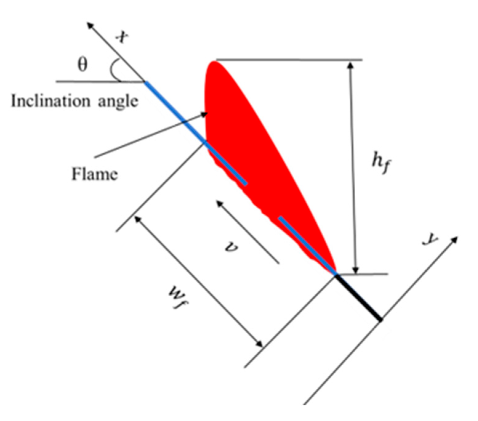
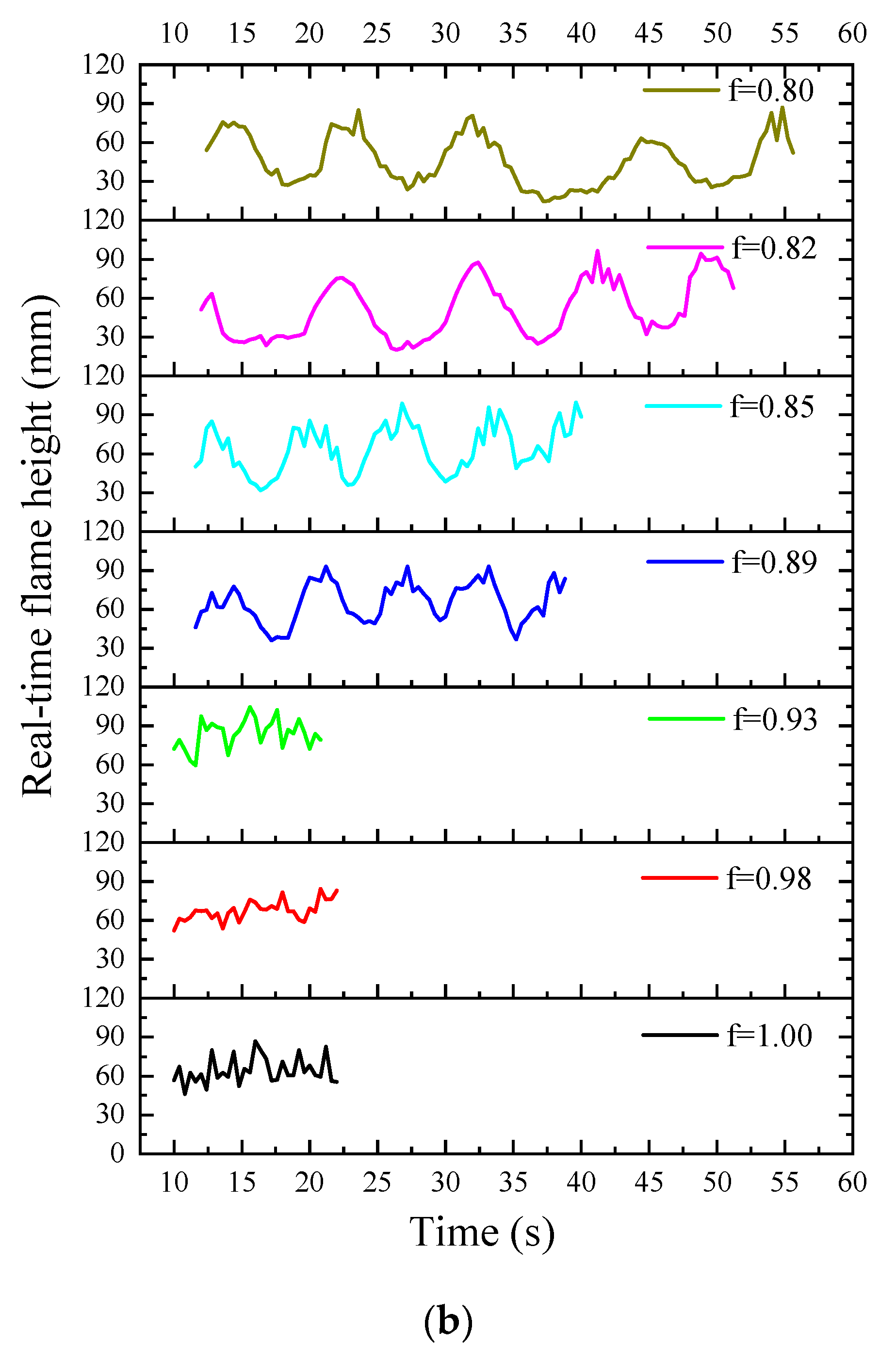
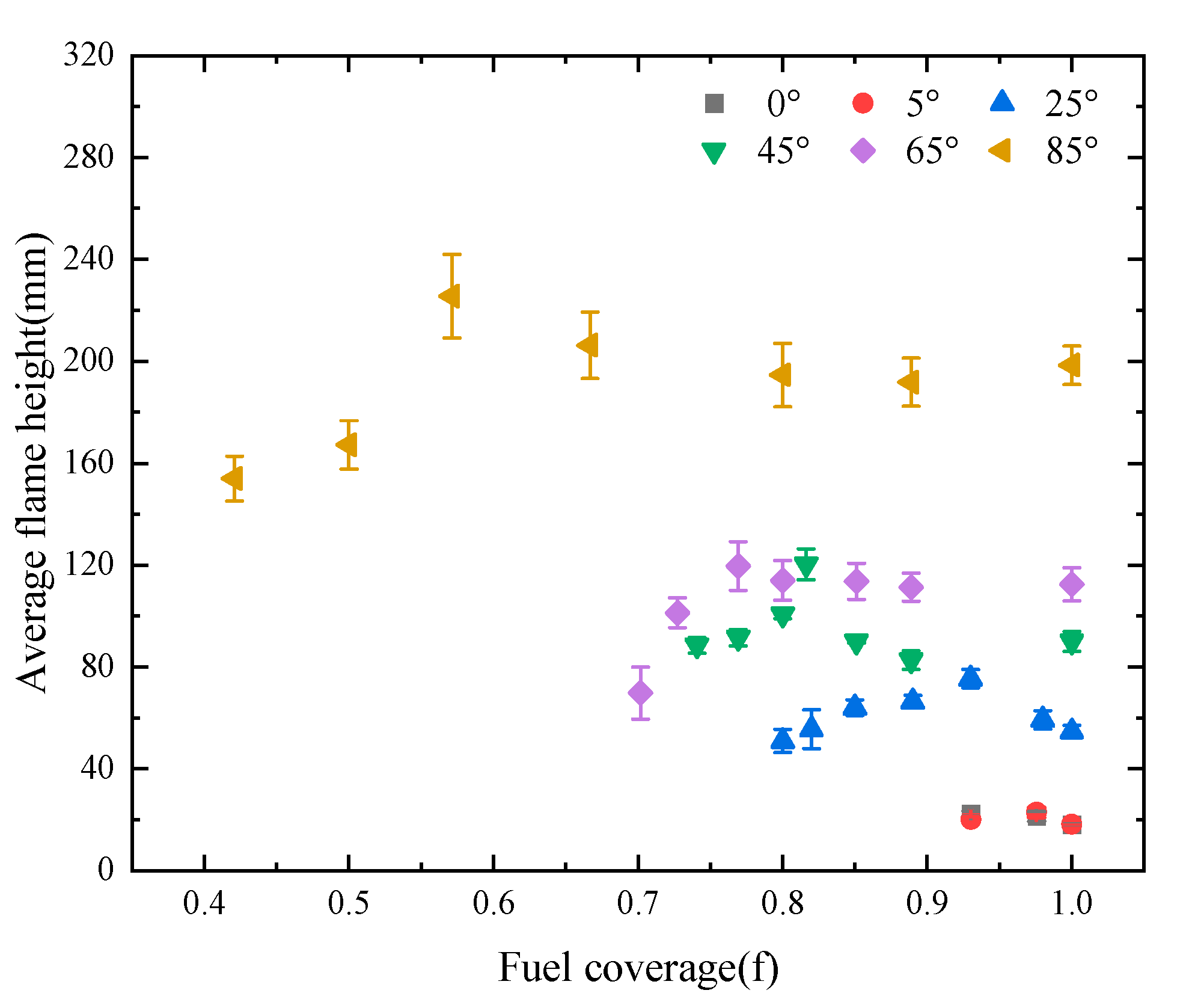
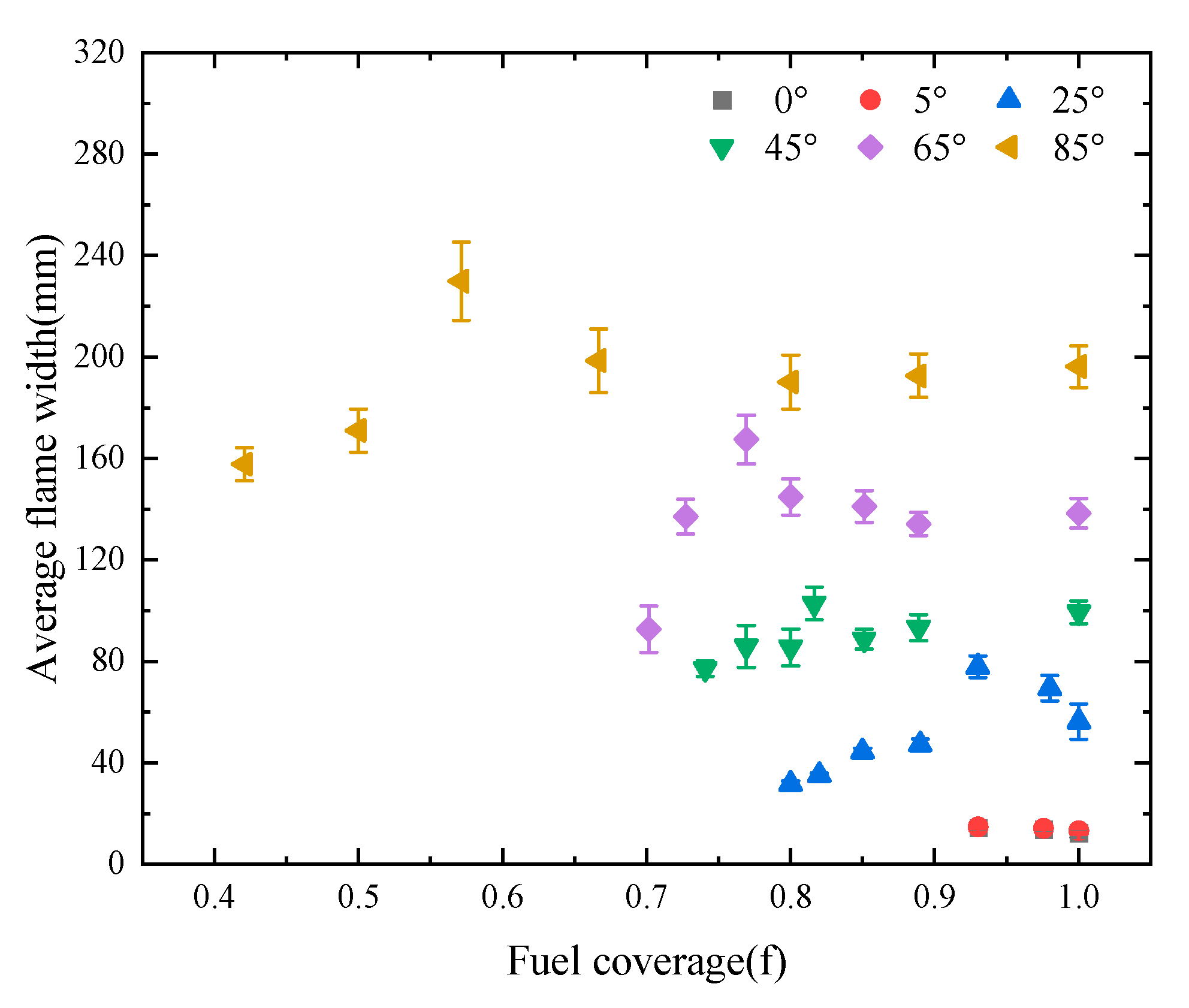
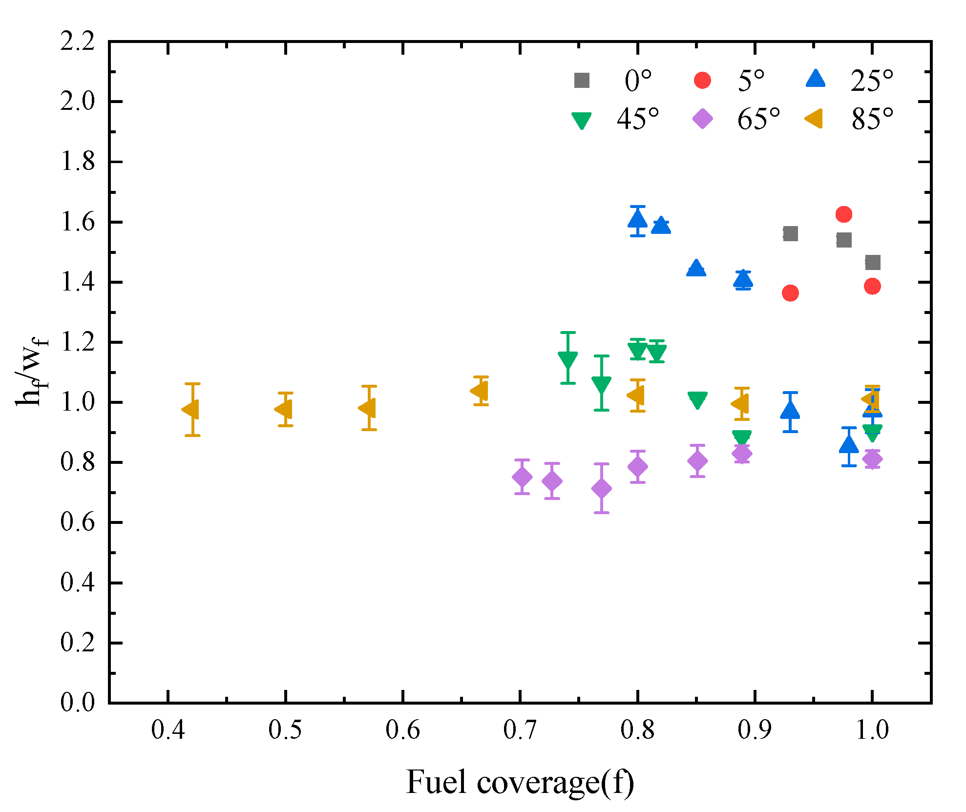
3.2. Characteristic Flame Lengths

Characteristic flame lengths are important to feature and quantify flame spread behaviors. Characteristic flame lengths, including flame height and flame width, are defined in Section 2. When measuring the flame lengths, the first and last pieces of the sample were removed to eliminate the effects of ignition and propagation completion. Flame height with a frequency of 50% in each period was taken as the average flame height, and the variation in average flame height with different fuel coverage rates is presented in Figure 6. The result indicates that the mechanism of flame spread changes with the increase in fuel coverage and fuel inclination angle. For the effect of air gaps, the average flame height firstly increased and then decreased with the increase in fuel coverage at fixed angle. The fuel coverage rates corresponding to the maximum average flame height decreased as the fuel inclination angle increased. When the fuel coverage decreased ( f c r < f < 1, where f c r represents the critical fuel coverage), the flame presented obvious turbulent characteristics, accompanied by significant shaking, which indicates that the relatively small air gap can promote the entrainment of air and the effective mixing of fuel, so that accelerated combustion and larger flame size can be observed. On the other hand, with the further decrease in fuel coverage, the larger air gap hindered flame propagation from one sample to the next, making the ignition of the subsequent sample increasingly difficult; thus, a smaller flame size was achieved. Additionally, it was observed that when the flame passed through the gap, the flame was relatively stable. In addition, the air gap slightly affected the average flame height at low angles (i.e., 0° and 5°). During the propagation process, the flame on the upper surface of the sample remained approximately in a vertical shape, and the flame shape changed very little under vertical thermal buoyancy. For the effect of the fuel inclination angle, following the increase in fuel inclination angle, the average flame height increased significantly. As the inclination angle increased, the degree of combustion and flame spread of the sample became increasingly severe, and the volume of the flame body became larger and closer to the inclined surface of the sample, which enhanced the heat transfer effect of the flame on the unburned sample. The average flame width, which can be defined as w f , can be deduced by calculating the average value, which can be seen in Figure 7. The result indicates that the average flame width is non-linearly related to fuel coverage and that the variation follows a similar pattern to that of the flame spread rate and average flame height.
Figure 8 illustrates the variation in the ratio of average flame height ( h f ) to average flame width ( w f ) relative to fuel coverage (f) across various tilt angles. At an angle of 85°, the average flame height is comparable to the average flame width, resulting in a ratio ( h f / w f ) of average flame height to average flame width close to 1, which is different from other inclination angles. As depicted in Figure 4, the flame is in close contact with the fuel surface at 85°. In the range of 0° to 65°, with constant fuel coverage, an increase in tilt angle leads to a reduction in the ratio of average flame height to average flame width, indicating the flame’s closer proximity to the fuel surface. In the range of 0° to 5°, the spacing between fuel elements minimally affects the flame, with ratios consistently greater than 1.3, as depicted in the typical flame images in Figure 3, indicating that the flames are distanced from the fuel surface. Between 25° and 65°, when comparing wide and narrow spacing, wider spacing exhibits larger ratios, signifying that the flames are situated farther from the fuel surface.

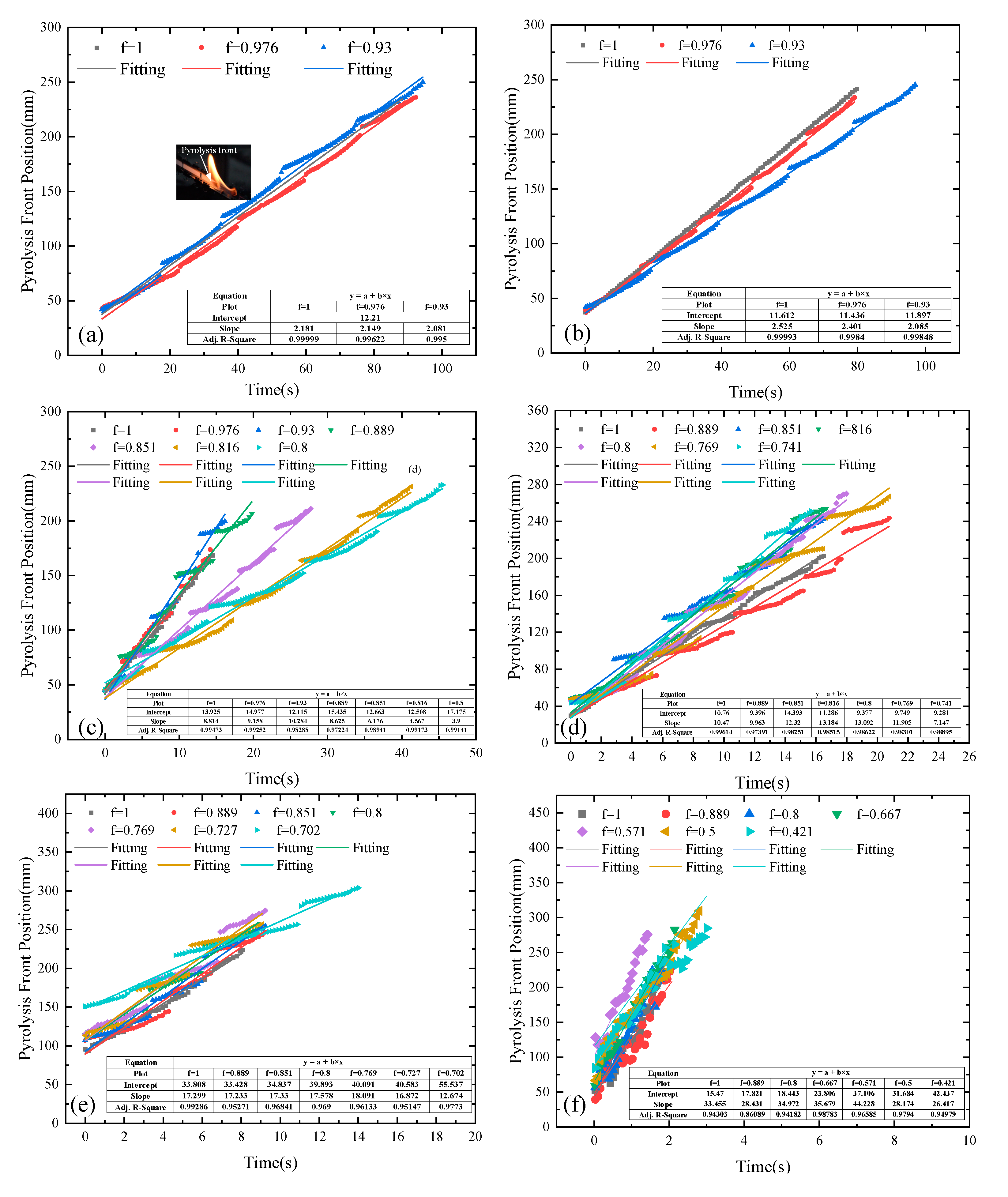
3.3. Flame Spread Rate

To obtain the flame spread rate, the real-time pyrolysis position was recorded. Image J was employed to extract and analyze the RGB images captured from side views and transformed into grayscale images. The statistical averaging of binary values at each pixel resulted in the creation of contour values representing the probability of flame presence. The pyrolysis front is easy to observe and measure, as shown in Figure 9, which shows the variation in the pyrolysis front with time under different fuel coverage rates. Splitting occurs when the flame crosses an air gap; therefore, the pyrolysis front is disconnected. In discrete fuel arrays, the flame spreads through the air gaps by jumping. The pyrolysis front reaches the edge of one unit of fuel, and the flame steadily raises the temperature of the adjacent unit, which then begins to pyrolyze and ignite. And that is the reason for the observed split in flame spread. From Figure 9, the flame spread rate being significantly increased can be described as fire jumping when the flame strides across the gap when the gap size is small, while as the gap size increases, the increase in flame spread rate is weakened. The reason is related to the longer ignition time or the weakening of the heating effect of adjacent fuel sheets as the gap size increases.
Despite the occurrence of splits, the real-time pyrolysis front still presented a fine linear relationship with time; thus, the flame spread rate could be determined by applying a linear fitting. As shown in Figure 9, the R-squared values of the linearly fitted curves for all experimental conditions are greater than 0.94, which indicates that the pyrolysis front position increased linearly with time. The average flame spread rate can be acquired by the slope of the linear fitting.
The average flame spread rates with different fuel coverage rates are presented in Figure 10. The results show that the flame spread rate remained basically unchanged at low angles (0° and 5°), while the flame spread rate firstly increased and then decreased at other angles with the increase in fuel coverage. The maximum flame spread rates occurred for the fuel coverage range of 0.571 to 0.93 for different inclination angles. Figure 11 illustrates the flame spread rate with different fuel inclination angles. The result shows that the flame spread rate increases with the increase in angle.
From a macro perspective, as the inclination angle of the sample increases, the flame body deviates significantly from the vertical state and moves towards the material, resulting in an increase in the preheating zone and an enhancement in the heat flux transferred from the flame to the unburned zone [30]. When the flame spreads along the direction of buoyancy brought by inclination, the fuel in the preheating zone is heated to produce pyrolysis gas by the flame above and below the sample simultaneously. As the gap size is relatively low, the mixing of pyrolysis gas and air is enhanced across the gap and the premixed gas near the next fuel unit is ignited by the flame above or below the fuel unit even though the previous unit has not been burned out yet, resulting in an increased flame spread rate. This accelerating effect of flame spread is called flame jumping. When the gap size is further increased, the competition between the acceleration effect of flame jumping is weakened and the cooling effect of the large gap size is formed, resulting in a decreased flame spread rate when fuel coverage falls below a certain threshold.
To further quantify the rate of flame spread, it is necessary to establish a theoretical model. According to classical flame spread theory, the flame spread rate ( v p ) over thermally thin material is related to the preheating length (δf) and the heat flux ( q ˙ f ) in the preheating zone [31]:
v p = δ f q ˙ f ( x ) d x f ρ τ c p ( T i g T )
where ρ, cp, τ, x, Tig, and T are the density, the specific heat, the thickness, the downstream distance position from the flame front, the ignition temperature, and the ambient temperature of the sample. For upward flame spread, the heat transfer from the flame to the virgin zone ahead of the flame front satisfies Equation (2) [32].
q ˙ f ( x ) = q ˙ f ( x ) μ [ Δ H c c p ( T i g T ) ] x Pr ( G r x ) 1 / 4
where q ˙ f ( x ) , μ , Δ H c , Pr , and G r x are the dimensionless heat flux, the dynamic viscosity of air, the heat of combustion of the sample, the Prandtl number, and the Modified Grashof number. G r x can be written as Equation (3) [32,33]:
G r x = g β ( T f T ) sin θ x 3 ν 2
where g, β , T f , θ , and ν are the gravitational acceleration, the thermal expansion coefficient of air, the flame temperature, the inclination angle of the sample, and the kinematic viscosity of air. The dimensionless heat flux ( q ˙ f ( x ) ) depends on the flame attachment length and x, which can be expressed as q ˙ f ( x ) = 0.56 ( x / w ) 2 , as proposed and verified by Ju et al. [32]. By bringing G r x and q ˙ f ( x ) into Equation (2), q ˙ f ( x ) can be rewritten as
q ˙ f ( x ) = 0.56 μ [ Δ H c c p ( T i g T ) ] [ g β ( T f T ) ] 1 / 4 Pr ν 1 / 2 · w f 2 sin θ 1 / 4 x 9 / 4
he thermophysical parameters of air and solid fuel, the ignition temperature, and the flame temperature are constants, and q ˙ f ( x ) can be simplified as χ · w f 2 sin θ 1 / 4 x 9 / 4 , where w f is the average flame width. So, Equation (1) can be expressed as
v p = δ f q ˙ f ( x ) d x f ρ τ c p ( T i g T ) = χ w f 2 sin θ 1 / 4 f ρ τ c p ( T i g T ) g + l g + 2 l x 9 / 4 d x = 0.2 χ w f 2 sin θ 1 / 4 f ρ τ c p ( T i g T ) ( 1 ( g + l ) 5 / 4 1 ( g + 2 l ) 5 / 4 )
As f = l / g + l , Equation (5) can be further expressed as follows:
v p = 0.2 χ ρ τ c p l 5 / 4 ( T i g T ) w f 2 sin θ 1 / 4 f 1 / 4 [ 1 - ( 1 + f ) 5 / 4 ]
Equation (6) gives the flame spread model, and the flame spread rate can be calculated by consulting the relevant parameters of paper and air. The relevant parameters of paper and air can be found from related literature [34], as shown in Table 2 and Table 3. A comparison of the theoretical calculations based on the flame spread model with the experimental data is plotted in Figure 12. The equation derived in the present study provides the evolutionary trend of the flame spread rate under the effect of inclination angles and gap sizes. Table 4 lists the values of pyrolysis length ( x p ). In this study, pyrolysis length is defined as the vertical distance from the bottom of the flame to the flame tip. It should be noted that the flame width in Equation (6) is replaced with the pyrolysis length because the experimental flame spread rate is obtained from the pyrolysis front. This is because of the adherence of the flame to the wall during the spread process. As the angle increases, the flame adheres more prominently to the wall, resulting in the flame front significantly outpacing the pyrolysis front. Consequently, the flame width is observed to be substantially greater than the pyrolysis width. When the flame width is utilized to calculate the rate of fire spread, it yields a significantly higher value compared with the experimentally measured rate, which is derived from the pyrolysis front. According to Figure 12, the predicted rate of flame spread exhibits satisfactory alignment with the experimental data. For cases with relatively small angle, the experimental and predicted values are relatively close. However, at large inclination angles, i.e., 85°, the predicted value deviates significantly from the experimental value. Perhaps due to the enhanced turbulence characteristics of air at high angles, the measurement of the pyrolysis front through video observation is not accurate because the flame obscures the traces of pyrolysis, especially the pyrolysis front. Additionally, the thermophysical parameters of air are defined as constants, which further leads to inaccuracies in the results. Nevertheless, the model of Equation (6) still provides a good explanation of the relationship among the flame spread rate, the inclination angle of fuel, and fuel coverage.
Moreover, based on our experimental findings, we observed that at certain angles, the flame spread rate initially increased and then decreased with the increase in fuel spacing until flame extinction occurred. We established a representation of the maximum flame spread rate and critical flame spread rate by using points positioned at the horizontal and vertical coordinates, indicating the fuel tilt angle and fuel coverage rate, respectively. Using the flame spread rate as a basis, the chart delineates three distinct regions characterized by the continuous flame spread line, the maximum flame spread line, and the critical flame spread line, as depicted in Figure 13. Region 1 represents the accelerated flame spread region, where the flame spread rate is increased by enhanced air entrainment and heat transfer. Region 2 is the flame spread weakening region, where the cooling effect of the large gap size plays the dominant role. Region 3 can be referred to as the failed flame spread region, where the flame cannot successfully spread due to the insufficient heat transfer to ignite the next fuel unit.

4. Conclusions

In this study, we designed 34 sets of fuel arrays, spanning six inclination angles (0°–85°) and incorporating various fuel coverage rates (0.421–1). We conducted a thorough analysis of typical flame phenomena and essential flame characteristic dimensions, including flame height, flame width, and flame spread rate. The main findings are summarized as follows:
  • At lower angles, the flame front exhibited a smooth envelope with minimal fluctuations. However, at higher inclination angles, turbulent flame structures became increasingly apparent. Nevertheless, the burning intensity diminished, resulting in more stable flames, especially when the gap distance was sufficiently large, even at high inclination angles. In instances of smaller gap distances, flames leaped across the air gap. As the gap distance increased, flames propagated across the gap by relying on continuous heating from the preceding fuel flame, often accompanied by flame splitting.
  • Both flame height and flame width exhibited an initial increase followed by a decrease with the increase in fuel coverage, reaching their peak values at specific points. Higher fuel coverage levels facilitated the entrainment of air and effective fuel mixing in the relatively small air gap, accelerating combustion and resulting in a larger flame size. Conversely, at low fuel coverage, larger air gaps hindered flame propagation due to the increasingly challenging ignition of the next sample, resulting in a smaller flame size.
  • The flame spread rate demonstrated an initial increase followed by a decrease with the increase in fuel coverage, reaching a maximum value at fuel coverage rates between 0.93 and 0.571 for various inclination angles. We proposed a theoretical model to predict flame spread which effectively elucidates and predicts the interplay among flame spread rate, inclination angle, and fuel coverage. Furthermore, we delineated distinct regions within the map formed by inclination angle and fuel coverage, including the accelerated flame spread region, the flame spread weakening region, and the failed flame spread region.
The phenomenon of flame propagation on inclined, discrete, thin fuels becomes increasingly complex in the presence of wind, as the involvement of wind significantly alters flow field characteristics, flame morphology, and heat transfer mechanisms [35]. The primary influence on combustion behavior of forced airflow is attributed to the horizontal momentum generated by the flow, counteracting the vertical buoyancy produced by the fire [36]. Research by Lai et al. [17] indicates that low-speed airflow can enhance combustion longevity and char yield, while high wind speeds can diminish combustion intensity. The involvement of different wind speeds adds further interest to our study, and our next step involves investigating flame propagation on inclined, discrete, thin fuels under varying wind speeds.

Author Contributions

X.Z.: Conceptualization; Formal analysis; Visualization; Writing—original draft; Resources. S.K.: Formal analysis; Visualization; Writing—original draft; Methodology. Y.Z.: Conceptualization; Formal analysis; Supervision; Writing—review and editing; Project administration. J.Z.: Writing—editing. S.L.: Funding acquisition; Writing—review and editing; Supervision. All authors have read and agreed to the published version of the manuscript.

Funding

This research was funded by Talent Introduction Project of Shanghai Institute of Technology (No. YJ2021-92), National Science Foundation of China (No. 52306144), and Shenzhen Science and Technology Program (No. KCXFZ20230731093902005).

Institutional Review Board Statement

Not applicable.

Informed Consent Statement

Not applicable.

Data Availability Statement

The raw data supporting the conclusions of this article will be made available by the authors on request.

Conflicts of Interest

The authors declare no conflicts of interest.

References

  1. Quintiere, J.G. Fundamentals of Fire Phenomena; John Wiley & Sons Ltd.: Chichester, UK, 2006. [Google Scholar]
  2. Watanabe, Y.; Torikai, H.; Ito, A. Flame spread along a thin solid randomly distributed combustible and noncombustible areas. Proc. Combust. Inst. 2011, 33, 2449–2455. [Google Scholar] [CrossRef]
  3. Gollner, M.J.; Xie, Y.; Lee, M.; Nakamura, Y.; Rangwala, A.S. Burning behavior of vertical matchstick arrays. Combust. Sci. Technol. 2012, 184, 585–607. [Google Scholar] [CrossRef]
  4. Miller, C.H.; Gollner, M.J. Upward flame spread over discrete fuels. Fire Saf. J. 2015, 77, 36–45. [Google Scholar] [CrossRef]
  5. Carrier, G.F.; Fendell, F.E.; Wolff, M.F. Wind-aided fire spread across arrays of discrete fuel elements. I. Theory. Combust. Sci. Technol. 1991, 75, 31–51. [Google Scholar] [CrossRef]
  6. Fernandez-Pello, A.C.; Williams, F.A. Laminar spread over PMMA surfaces. In Symposium (Int.) on Combustion, 15th ed.; The Combustion Institute: Pittsburgh, PA, USA, 1975. [Google Scholar]
  7. Fernandez-Pello, A.C.; Santoro, R.J. On the dominant mode of the transfer in downward flame spread. In Symposium (International) on Combustion, 17th ed.; The Combustion Institute: Pittsburgh, PA, USA, 1979. [Google Scholar]
  8. Iii, M.A.; Magee, R.S. The mechanism of flame spreading over the surface of igniting condensed-phase materials. Symp. Combust. 1969, 12, 215–227. [Google Scholar]
  9. Orloff, L.; De Ris, J.; Markstein, G.H. Upward turbulent fire spread and burning of fuel surface. In Symposium (International) on Combustion, 15th ed.; The Combustion Institute: Pittsburgh, PA, USA, 1975. [Google Scholar]
  10. Di Blasi, C.; Crescitelli, S.; Russo, G. Near-Limit Flame Spread over Thick Fuels in a Concurrent Forced Flow. Combust. Flame 1988, 72, 205–212. [Google Scholar] [CrossRef]
  11. Quintiere, J. Fire Spread on Surfaces and Through Solid Media. In Fundamentals of Fire Phenomena; John Wiley & Sons Ltd.: Hoboken, NJ, USA, 2006; pp. 191–225. [Google Scholar]
  12. Vogel, M.; Williams, F.A. Flame propagation along matchstick arrays. Combust. Sci. Technol. 1970, 1, 429–436. [Google Scholar] [CrossRef]
  13. Finney, M.A.; Cohen, J.D.; Grenfell, I.C.; Yedinak, K.M. An examination of fire spread thresholds in discontinuous fuel beds. Int. J. Wildland Fire 2010, 19, 163–170. [Google Scholar] [CrossRef]
  14. Di Cristina, G.; Skowronski, N.S.; Simeoni, A.; Rangwala, A.S.; Im, S.K. Flame spread behavior characterization of discrete fuel array under a forced flow. In Proceedings of the 38th International Symposium on Combustion, Adelaide, Australia, 24–29 January 2021; Elsevier Limited: Amsterdam, The Netherlands, 2021. [Google Scholar]
  15. Gollner, M.; Huang, X.Y.; Cobian, J.; Rangwala, A.S.; Williams, F.A. Experimental study of upward flame spread of an inclined fuel surface. Proc. Combust. Inst. 2013, 34, 2531–2538. [Google Scholar] [CrossRef]
  16. Prahl, J.M.; Tien, J.S. Preliminary investigations of forced convection on flame propagation along paper and matchstick arrays. Combust. Sci. Technol. 1973, 7, 271–282. [Google Scholar] [CrossRef]
  17. Lai, Y.; Wang, X.; Rockett, T.B.; Willmott, J.R.; Zhang, Y. Investigation into wind effects on fire spread on inclined wooden rods by multi-spectrum and schlieren imaging. Fire Saf. J. Int. J. Devoted Res. Fire Saf. Sci. Eng. 2022, 127, 103513. [Google Scholar] [CrossRef]
  18. Hwang, C.C.; Xie, Y. Flame propagation along Matchstick Arrayson, inclined base boards. Combust. Sci. Technol. 1984, 42, 1–12. [Google Scholar] [CrossRef]
  19. Ohtani, H.; Ohta, K.; Uehara, Y. Effect of orientation on burning rate of solid combustible. Fire Mater. 1991, 15, 191–193. [Google Scholar] [CrossRef]
  20. Park, J.; Brucker, J.; Seballos, R.; Kwon, B.; Liao, Y.T.T. Concurrent flame spread over discrete thin fuels. Combust. Flame 2018, 191, 116–125. [Google Scholar] [CrossRef]
  21. Cui, W.; Liao, Y.T.T. Experimental study of upward flame spread over discrete thin fuels. Fire Saf. J. 2019, 110, 102907. [Google Scholar] [CrossRef]
  22. Luo, S.; Zhao, Y.; Zhang, H. Numerical study on opposed-flow flame spread over discrete fuels—The influence of gap size and opposed-flow velocity. Fuel 2021, 283, 118862. [Google Scholar] [CrossRef]
  23. Wang, Z.; Liang, W.; Cai, M.; Tang, Y.; Li, S.; An, W.; Zhu, G. Experimental study on flame spread over discrete extruded polystyrene foam with different fuel coverage rates. Case Stud. Therm. Eng. 2020, 17, 100577. [Google Scholar] [CrossRef]
  24. An, W.; Cai, M.; Tang, Y.; Li, Q.; Wang, Z. Influence of inclined angle on upward flame spread over discrete extruded polystyrene foam. Combust. Sci. Technol. 2020, 194, 1301–1320. [Google Scholar] [CrossRef]
  25. Beer, T. Fire propagation in vertical stick arrays—The effects of wind. Int. J. Wildland Fire 1995, 5, 43–49. [Google Scholar] [CrossRef]
  26. Pizzo, Y.; Consalvi, J.L.; Querre, P.; Coutin, M.; Porterie, B. Width effects on the early stage of upward flame spread over PMMA slabs: Experimental observations. Fire Saf. J. 2009, 44, 407–414. [Google Scholar] [CrossRef]
  27. Dold, J.W.; Zinoviev, A. Fire eruption through intensity and spread rate interaction mediated by flow attachment. Combust. Theory Model. 2009, 13, 763–793. [Google Scholar] [CrossRef]
  28. Finney, M.A.; Cohen, J.D.; Forthofer, J.M.; McAllister, S.S.; Gollner, M.J.; Gorham, D.J.; Saito, K.; Akafuah, N.K.; Adam, B.A.; English, J.D. Role of buoyant flame dynamics in wildfire spread. Proc. Natl. Acad. Sci. USA 2015, 112, 9833–9838. [Google Scholar] [CrossRef] [PubMed]
  29. VM, J.; Ambatipudi, M.K. The phenomenon of flame jump in counter–current flame propagation in biomass packed beds–experiments and theory. Combust. Sci. Technol. 2022, 194, 1199–1212. [Google Scholar]
  30. Heskestad, G. Fire plumes, flame height, and air entrainment. In SFPE Handbook of Fire Protection Engineering; Springer: Berlin/Heidelberg, Germany, 2016; pp. 396–428. [Google Scholar]
  31. Carney, A.; Li, Y.; Liao, Y.T.; Olson, S.; Ferkul, P. Concurrent-flow flame spread over thin discrete fuels in microgravity. Combust. Flame 2021, 226, 211–221. [Google Scholar] [CrossRef]
  32. Ju, X.; Gollner, M.J.; Wang, Y.; Tang, W.; Zhao, K.; Ren, X.; Yang, L. Downstream radiative and convective heating from methane and propane fires with cross wind. Combust. Flame 2019, 204, 1–12. [Google Scholar] [CrossRef]
  33. Morton, B.R. Modeling fire plumes. In Symposium (International) on Combustion; Elsevier: Amsterdam, The Netherlands, 1965; Volume 10, pp. 973–982. [Google Scholar]
  34. Chen, X.; Liu, J.; Zhou, Z.; Li, P.; Zhou, T.; Zhou, D.; Wang, J. Experimental and theoretical analysis on lateral flame spread over inclined PMMA surface. Int. J. Heat Mass Transf. 2015, 91, 68–76. [Google Scholar] [CrossRef]
  35. Hu, L. A review of physics and correlations of pool fire behaviour in wind and future challenges. Fire Saf. J. 2017, 91, 41–55. [Google Scholar] [CrossRef]
  36. Lin, Y.; Hu, L.; Zhang, X.; Chen, Y. Experimental study of pool fire behaviors with nearby inclined surface under cross flow. Process Saf. Environ. Protect. 2021, 148, 93–103. [Google Scholar] [CrossRef]
Figure 1. The diagrammatic sketch of the experimental apparatus and the sample layout.
Fire 07 00177 g001
Figure 2. The definition of the characteristic flame size.
Fire 07 00177 g002
Figure 3. Typical flame images with different fuel coverage at low inclination angles (0° and 5°).
Fire 07 00177 g003
Figure 4. Typical flame images with different fuel coverage at inclination angles from 25° to 85°.
Fire 07 00177 g004
Figure 5. The real-time flame height with time: (a) the real-time flame height over continuous samples (f = 1) with different inclinations; (b) the real-time flame height with different fuel coverages (f) at 25°.
Fire 07 00177 g005aFire 07 00177 g005b
Figure 6. The dependence of the average flame height on different fuel coverage rates.
Fire 07 00177 g006
Figure 7. Average flame width for different fuel coverage rates.
Fire 07 00177 g007
Figure 8. The relationship between the ratio ( h f / w f ) of average flame height to average flame width and the fuel coverage rate (f).
Fire 07 00177 g008
Figure 9. Variation in pyrolysis front height with time for different fuel coverage rates in different fuel angular orientations. (a) 0°; (b) 5°; (c) 25°; (d) 45°; (e) 65°; (f) 85°.
Fire 07 00177 g009
Figure 10. The average spread rate versus the fuel coverage rate with different inclination angles: (a) 0° ≤ θ ≤ 85° and (b) 0° ≤ θ ≤ 65°.
Fire 07 00177 g010
Figure 11. The average spread rate versus fuel angular orientations with different fuel coverage rates: (a) all the fuel coverage rates; (b) partial enlargement.
Fire 07 00177 g011
Figure 12. Comparison between the calculated flame spread rates and the measured values for different fuel coverage and inclination angle values according to Equation (6).
Fire 07 00177 g012
Figure 13. Distribution of flame spread regimes for different inclination angle and fuel coverage values.
Fire 07 00177 g013
Table 1. Test matrix (fuel segment length, l = 40 mm).
θ (°)g (mm)fθ(°)g (mm)f
001501
10.97610.976
30.93030.930
25014501
10.97650.889
30.93070.851
50.88990.816
70.851100.8
90.816120.769
100.8140.741
65018501
50.88950.889
70.851100.8
100.8200.667
120.769300.571
150.727400.5
170.702550.421
Table 2. The relevant parameters of air.
PrβT (K)ν (m2 s−1)μ (Pa·s)Tf (K)
0.7 [34]0.0036729814.8 × 10−617.9 × 10−61073 [34]
Table 3. The relevant parameters of paper.
τ (m)Tig (K)cp (kJ/(kg·°C))ρ (kg·m−3)θ (°)
0.274 × 10−34562.00.6 × 1030–85
Table 4. The pyrolysis length (xp).
θ (°)fxp (mm)θ (°)fxp (mm)
25150.27345159.4
0.97648.5760.88954.582
0.93057.1520.85163.012
0.88949.1820.81668.159
0.85144.4250.859.003
0.81634.90.76953.075
0.831.740.74149.101
65171.998851126.154
0.88967.0010.889122.603
0.85166.0130.8125.112
0.875.9760.667136.525
0.76983.8990.571159.882
0.72775.9250.5131.015
0.70255.890.421130.71
Disclaimer/Publisher’s Note: The statements, opinions and data contained in all publications are solely those of the individual author(s) and contributor(s) and not of MDPI and/or the editor(s). MDPI and/or the editor(s) disclaim responsibility for any injury to people or property resulting from any ideas, methods, instructions or products referred to in the content.

