Abstract
Consideration of appropriate fire scenarios in the simulations of the Fire Dynamics Simulator (FDS) for the fire-risk assessment of buildings is a critical factor in the development of prevention and response measures. The user dependence of the FDS input parameters can threaten the reliability of the fire-risk assessment. An experimental study was conducted to establish correlations for considering appropriate fire scenarios using polymethyl methacrylate. To examine the changes in the maximum-heat-release rates (HRRs) according to the combustion environment, nine burners varying in size at 25 mm intervals were burned in open and compartment environments. The results indicated that compared with the fire phenomenon in the open environment, the maximum HRR and fire growth rate of the compartment fire were increased by factors of 3–50. Additionally, the compartment fire phenomena could be classified into three stages according to the changes in the aforementioned two physical quantities. An analysis of the experimental results revealed a correlation for predicting the maximum HRR of a compartment fire with various ventilation conditions using only the experimental results for the open environment. The maximum HRR predicted through this correlation exhibited an error of <15% relative to the values measured in the experiment.
1. Introduction
Currently, the fire safety of buildings and facilities is evaluated via creating a performance-based design (PBD) to overcome the limitations of their physical structures and statutory fire-protection designs. The fire risk of a building is assessed using fire simulation, and the Fire Dynamics Simulator (FDS) [1] is widely used for this purpose. In PBD, engineers perform fire simulations that consider the shape, boundary conditions, and fire scenarios of the building to predict the fire phenomena. In FDS, a fire scenario is set by entering the fire source considering the purpose, size, ignition location, and type of combustible material of the building. Therefore, accurately predicting the potential fire risk of a building through fire simulation and devising measures for it requires the essential selection of appropriate fire scenarios.
The reliability of the FDS has been continuously verified by its developer—the U.S. National Institute of Standards and Technology—and its users [2,3,4,5,6]. Nonetheless, the prediction reliability of fire phenomena using FDS could be compromised by user dependence on input variables. At the current stage, FDS has limitations in predicting fire spread on combustible surfaces and fire phenomena in under-ventilated conditions [7,8,9,10]. Thus, in fire simulations, fire source information consisting of the fire growth rate and maximum-heat-release rate (HRR) is entered for fire-risk assessment. The components of the fire source are selected and entered according to the engineering judgment of the engineers, who refer to the literature on the combustibles which are determined according to fire scenarios. However, even if they are the same combustibles, the fire phenomenon undergoes major changes owing to factors such as the building shape and ventilation conditions. If an inappropriate fire source is cited without considering the influences of these factors, the predicted fire phenomena may differ significantly from reality [11], and the reliability of fire-risk assessment can be significantly undermined.
Various methods have been developed to prevent the reliability reduction of fire-risk assessment due to inappropriate fire-source inputs. The derivation of the fire-source area based on the shape and placement of combustibles [12] and a statistical analysis of Heat Release Rate Per Unit Area (HRRPUA) based on building use [13] were conducted. Furthermore, the New Zealand architecture law C/VM2 [14] and Fleischmann [15] presented guidelines that engineers can refer to for the input of HRRPUA (kW/m2) according to the use of buildings. In addition, full-scale fire experiments were performed on potential targets of PBD with the aim of obtaining a database for various fire conditions [16,17,18]. Despite these studies, the fire source for fire-risk assessment is dependent on the subjective choice of the user owing to the high levels of uncertainty of fire phenomena and the fire-source area, which depend on the building shape and ventilation conditions.
In the previous studies, to solve these problems, we investigated the correlations of the maximum HRR with the building shape and ventilation conditions. Through a numerical analysis, the correlations of the maximum HRR with the size of the PBD target building and the fire growth rate were obtained, and their applicability was verified [19,20]. The correlations were useful for considering the worst-case fire scenario for the given building. However, since it considered only enclosed compartments, it has limitations in terms of applicability. Accordingly, experimental investigations were conducted to examine the variations in the maximum-heat-release rates of wood, liquid combustibles, and cables in open environments, and compartments with varying opening shapes [21,22,23]. As a result, despite analyzing the quantitative changes in the maximum HRRs of combustibles according to the combustion environment and their causes, correlations universally applicable to all types of combustibles were not established.
In this context, an experimental study using PMMA was conducted. The main objective of this study was to derive correlations to predict changes in the maximum-heat-release rate based on the combustion environment (compartment and ventilation conditions). Because PMMA—a well-known typical thermoplastic—melts and burns when heated, it has the complex fire characteristics of having solid and liquid fuels. Various sizes of burners containing PMMA pellets were burned in an open environment and in compartment environments with varying ventilation conditions. Through comparison of the maximum HRR according to fire conditions, correlations were derived to predict the maximum HRR of a compartment fire using experimental results in an open environment. The maximum HRRs of compartment fires predicted, reflecting the influence of ventilation conditions, showed small errors of less than 15% compared to those measured in experiments.
2. Experiments
Figure 1 presents photographs of the experimental setup and combustibles used to examine the changes in the fire phenomena of PMMA in open and compartment environments under various ventilation conditions. Figure 1a shows a schematic of the ISO 9705 room at 1/4 scale. The outer wall of the compartment is made of steel (thickness = 5 mm), and the interior space, finished with cerakwool (thickness = 25 mm), has dimensions of 0.6 m (width, x), 0.9 m (depth, y), and 0.6 m (height, z). For reference, the compartment experimental apparatus used in this study is the same as that used in previous studies [22,23]. In order to implement various ventilation conditions in the compartment environment, the door width (DW) was changed. Specifically, the door width was reduced at 25% (0.05 m) intervals based on the opening size (W = 0.2 m, H = 0.5 m) which was reduced to the same ratio as the compartment. Changes in the opening height result in changes in the position of the neutral plane and the internal pressure field, which may affect the fire characteristics. Considering this, the opening height was fixed at 0.5 m. Thus, four opening shapes with equal heights of 0.5 m and widths of 0.20, 0.15, 0.10, and 0.05 m were considered. The openings were named DW20 to DW05, depending on the DW. Inside the compartment, thermocouple trees and plate thermometers were installed for temperature and heat flux measurement, and each location is shown in the figure. Figure 1b shows photographs of the PMMA pellets considered as combustibles in this study. Burners of various sizes were used to examine, in detail, the changes in the maximum HRR according to the combustion environment and ventilation conditions of the compartment. Specifically, nine conditions were considered where one side (L) of the square steel burner was varied from 100 to 300 mm at 25 mm intervals. The burners were named L100–L300 according to their L value. The depths of all the burners were unified to 40 mm, and the heights of the contained combustibles were unified to 15 mm. Moreover, 5 g of heptane was injected for the initial ignition of the combustibles. Each burner was placed at the center of the compartment floor and burned in the open environment and in the compartments with previously considered DW20 to DW05 openings. In all the experiments, the fuel mass loss rate (MLR) and HRR were measured using a load cell and an oxygen-consumption calorimeter, respectively. Details regarding the oxygen consumption calorimeter used for the HRR measurements were presented in a previous work [24]. Table 1 presents the opening and fire source conditions used in the present study, along with the corresponding fuel masses.
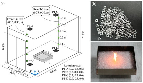
Figure 1.
Experimental setup: (a) schematic diagram of the compartment apparatus and measurement devices; (b) photos of combustibles (PMMA) and square burner.

Table 1.
Summary of experimental conditions.
3. Results and Discussion
A review and comparison of the inherent fire characteristics in an open environment that is not affected by the thermal feedback of the compartment environment and the ventilation conditions can help us to better understand the compartment fire phenomenon. Accordingly, all the fire sources considered were burned in an open environment, and Figure 2 presents photographs of the instantaneous flame at the peak. In the experiments, a wider fire source area corresponded to a longer flame. Furthermore, from the spread of the flame throughout the burner, it was inferred that the PMMA at the peak was in a liquid form. The combustion continued for a long time even after the fuel was completely melted; however, boiling did not occur, regardless of the burner size. Although the fire phenomenon of PMMA can be partially understood from these qualitative characteristics, quantitative measurement of physical quantities is also an essential element. Accordingly, the MLR and HRR of experiments conducted in an open environment were measured. The measurement results were used as the standard for analyzing changes in fire phenomena in compartment environments with various ventilation conditions.
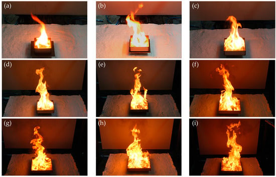
Figure 2.
Photographs of the instantaneous flame at the peak for different burner sizes in an open environment: (a) L100; (b) L125; (c) L150; (d) 175; (e) 200; (f) 225; (g) 250; (h) 275; (i) 300.
Compared with the fire phenomenon of PMMA in the open environment, the compartment environment varied depending on the ventilation conditions and the burner size. These phenomena can be categorized into three types. Figure 3 shows each phenomenon’s HRR and flame shape for a compartment fire experiment with DW20. Additionally, experimental results obtained using burners of the same size in the open environment are presented for comparison. In the figure, the subscripts c and o denote compartment and open environments, respectively. The first fire phenomenon of PMMA in a compartment environment is that the heat-release rate and flame shape do not change, as shown in Figure 3a. This phenomenon is primarily observed in experiments with relatively small burners, and the presumed cause is that the thermal feedback from the upper layer and wall, based on the amount of heat supplied from the fire source, is not sufficient to promote the combustion of combustibles. Consequently, the fire growth rate, maximum HRR, and fire duration were similar to the results of the open environment experiment. Additionally, there was no significant difference in the flame shape. In this study, this classification was called the ‘no-change’ phase. In the second phenomenon, the burning of combustibles in the compartment was promoted, as shown in Figure 3b. The fire in the open environment grew relatively slowly (), exhibiting a maximum HRR of approximately 20 kW, and was then extinguished upon the exhaustion of the combustibles. In contrast, the fire growth rate () and the maximum HRR (approximately 40 kW) of compartment fire were increased by factors of 2–3. As a result, the fire duration in the compartmentalized environment was approximately 1600 s, which was reduced by 20% compared to the open environment. In this phase, the flame length increased due to the increase in fuel supply per unit time due to combustion promotion, but no flame ejection was observed through the opening. Therefore, it can be considered as a ‘promoted’ phase if there is sufficient airflow to prevent flame ejections, even when the overall fire intensity increases due to thermal feedback in the compartment environment. The final category of the compartment fire phenomena occurred when the completely melted PMMA boiled, as shown in Figure 3c, which produced the largest change in the fire phenomenon. The maximum HRRs differed significantly between the open environment (approximately 40 kW) and the compartment environment (approximately 120 kW). For the fire growth rate, the initial value () for a compartment fire was similar to that for the open environment (). However, the fire growth rate () after the boiling was >50 times higher than that for the open environment. This phase, which is mostly characterized by flame ejection through the opening, was named ‘boiling’. Considering these results, changes in the overall fire phenomenon due to the combustion environment and ventilation conditions can lead to great uncertainty in predicting the fire risk of buildings and developing effective countermeasures and preventive measures. Therefore, predictions of the compartment-fire phenomena according to ventilation and fire-source conditions are required.
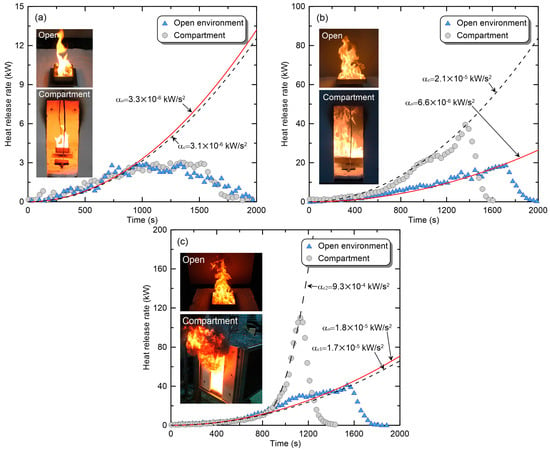
Figure 3.
Classification of compartment fire phenomena through comparison with fire phenomena in an open environment: (a) no change phase (L100); (b) promoted phase (L250); (c) boiling phase (L300).
Figure 4 presents a comparison of the maximum MLRs () and maximum HRRs () measured in open and compartment environments. Figure 4a shows the value of the compartment fire directly (the dash-dot line means 1:1 ratio), compared in a function form with the measured value in the open environment. Regardless of the opening shape, the in the compartment environment exhibits similar behavior. Under the conditions of relatively small burners, there is no significant difference observed between the measurements in compartment and open environments. However, as the burner size expands, the in the compartment environment shows a sharp increase, and after this increase, the gradually increases with a gentle slope with expansion of the burner size. Although the overall trend is similar, the size of the burner where the transition between phases occurs varies depending on ventilation conditions, that is, the opening shape. These results are also observed in Figure 4b, which shows a direct comparison of . Looking at the experimental results of DW05, where this phenomenon is most prominent, burners from L100 to L175 show values similar to those in an open environment (no-change). However, there is a sharp increase in with the transition to the ‘promoted’ phase in the L175~L200 section, followed by a gradual increase with a gentle slope in the ‘boiling’ phase corresponding to the L200~L300 burner conditions. The cause of the change in the increasing trend of in each phase can be explained through the relationship between air inflow and fuel supply. If the air inflow relative to the fuel supply is sufficient, the fuel is only burned inside the compartment. Thus, an increase in the burner size in the ‘promoted’ phase resulted in increased thermal energy and thermal feedback in the compartment, creating a virtuous cycle of fire growth. Consequently, increased sharply, as in the L175–L200 section. However, when the fuel supply (∴burner size) constantly increased and the air inflow became insufficient, a transition to under-ventilated fire (UVF) occurred. Under UVF conditions, part of the fuel burns incompletely within the compartment, while another part is discharged outside the compartment and then combusts in contact with oxygen. At this time, the amount of fuel burned inside the compartment is determined by the amount of air inflow, that is, the opening shape. Because of this, under UVF conditions, the amount of fuel burning within the compartment does not change significantly even if the burner size is expanded. Thus, the of the ‘boiling’ phase increased slowly. Considering Figure 4a,b from this perspective, the aforementioned changes in the fire phenomena of the three phases are observed equally in all the opening conditions. However, the burner size (L) in which the fire phenomenon changed, and the increases in the physical quantities, tended to depend on the opening shape. Specifically, a narrower door width results in the transition to the ‘promoted’ phase under smaller-burner-size conditions. This can be explained by the results of a previous study [23] on the fire phenomenon of heptane fuel. If the door width is reduced, the cooling effect of air inflow is suppressed, causing the rapid formation of the high-temperature top layer, which facilitates burning. Furthermore, with a narrower opening, a smaller change in the fire phenomenon occurs during switching to the ‘boiling’ phase. The cause is the circulation flow formed inside the compartment under under-ventilated conditions, which restricts the discharge of combustion products and the inflow of oxygen, hindering fire growth [23], and the heat energy within the compartment decreases due to flame ejection. Considering this, it is necessary to conduct an analysis and derive correlations that reflect the effects of changes in ventilation conditions on compartment fire phenomena.
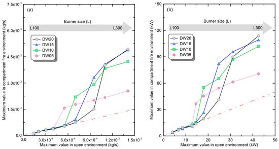
Figure 4.
Changes in representative physical quantities of compartment fire according to the ventilation conditions and burner size: (a) maximum-mass-loss rate; (b) maximum-heat-release rate.
To establish correlations for the maximum-heat-release rate, reflecting the influence of ventilation conditions, the concept of global equivalence ratio (GER, ) [25] can be employed. The GER is a measure to quantitatively evaluate the ventilation conditions of compartment fires based on fuel supply () and air inflow (), and it has been confirmed that it can be used to understand fire phenomena [26,27]. The GER is given using Equation (1), where represents the ratio of molecular mass between oxygen and fuel (≈1.92 for PMMA) for complete combustion, and is the mass fraction (0.233) of oxygen in the atmosphere. In addition, the air inflow () through the opening can be determined using the ventilation factor (, kg/s), considering the opening area () and height (). The ventilation factors of the openings considered in this study are presented in Table 1.
In Equation (1), , , and are fixed constants, obtained through consideration of combustible properties and compartment shape. However, the fuel supply rate () varies with the combustion environment, so without conducting experiments, its value cannot be determined, and a correlation cannot be derived. To solve this problem, it is necessary to derive a correlation using only the given information, such as the results of experiments in the open environment. Accordingly, the concept of the quasi-global equivalence ratio (quasi-GER, ), defined using Equation (2) has been employed in the present study. The Quasi-GER represents a virtual global equivalence ratio obtained when the maximum mass loss rate () measured in an open environment is applied to a building with arbitrary ventilation conditions ().
To infer correlations, Figure 5a presents Ratio , i.e., the ratio of the maximum HRR in the compartment environment to the value in the open environment, as a function of . Additionally, for a quantitative assessment of changes in the maximum-heat-release rate, a range of ±15%, known as the measurement uncertainty of the HRR, is also presented in the figure [28]. If falls in the range of 1.0 ± 0.15, it can be considered to correspond to the ‘no-change’ phase. Under small-burner conditions, exhibited the characteristics of the ‘no-change’ phase, falling within the range of 1.0 ± 0.15. As the burner size expanded, exhibited a sharp increase and a linear reduction because of the transition to the ‘promoted’ and ‘boiling’ phases. When considering this nonlinear behavior, individual correlations based on the classification of fire phases presented in Figure 3 should be derived. However, of the 36 conditions (four vents and nine burners) considered in the study, the ‘promoted’ phase was only observed in two experiments (DW20-L250 and DW15-L225) and not in DW10 and DW05 openings. Thus, the ‘promoted’ phase is speculated to be an intermittent phenomenon that occurs when the ‘no-change’ phase has transitioned to the ‘boiling’ phase. Additionally, due to the insufficient data available for the ‘promoted’ phase, correlations were derived solely for the ‘no-change’ and ‘boiling’ phases. In the ‘no-change’ phase, the critical value of at which the variation of exceeds the ±15% range varies depending on the opening shape. Accordingly, in Figure 5b, the variation of critical based on the ventilation factor for each opening was examined, and its relationship was confirmed to be defined as per Equation (3). The critical for each opening was determined using the largest value among the burners falling into the ‘no-change’ phase. Equation (3) demonstrates a remarkably high concordance, with an R-square value of 0.988. Nevertheless, considerable care must be taken in the classification of fire phenomena using Equation (3). As mentioned previously, we only considered the correlation between the ‘no-change’ and ‘boiling’ phases. If each phenomenon is classified and correlated on the basis of Equation (3), the predicted maximum HRR may have a significant error. For example, DW20 and DW10 in Figure 5b have values greater than the predicted critical according to Equation (3). Thus, the two fire conditions will be classified as the ‘boiling’ phase and can suffer major errors as separate correlations are applied. To prevent this error, a modified correlation was proposed, which could simply correct the error while having a range similar to the confidence interval (CI = 95%) of Equation (3). The modified correlation is defined using Equation (4), considering a margin of 10% for the critical in each ventilation condition. As shown in Figure 5b, the fitting line of Equation (4) can be utilized because it does not overlap with the area of the ‘boiling’ phase. In the future, research will be conducted to determine the boundaries of each phase and derive correlations for the ‘promoted’ phase. In conclusion, if the obtained by substituting , obtained in an open environment, into Equation (2), below is the critical value determined using Equation (4), and the compartment fire is classified as the ‘no-change’ phase. Moreover, the experimental results in an open environment can be directly utilized as an input parameter for simulating building fires without additional preprocessing.
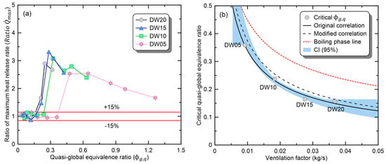
Figure 5.
Examination of the correlation between quasi-GER () and ratio of maximum HRR () in the no-change phase: (a) ratio of maximum HRR; (b) correlation.
The reason for having different critical values for each opening shape can be explained by considering the fire characteristics of the ‘no-change’ phase. In the classification based on the ventilation conditions, ‘no-change’ is the over-ventilated fire (OVF) condition and corresponds to a fuel-controlled fire. Under the OVF condition that the compartment and opening shapes are the same, the temperature increase ∆T of the OVF varies as a function of the HRR, as given using Equation (5) [29]. Here, , , , and denote the outward mass flow rate through an opening (kg/s), specific heat of gases (kJ/kg∙K), effective heat conduction term for the solid (kw/m2∙K), and boundary surface area (m2), respectively.
Figure 6a shows the average value of the maximum temperature measured at the front and back of the upper compartment. The temperature increased with the burner size for all the opening conditions. However, a change in the opening shape under the same burner size caused another change in the thermal environment inside the compartment. Comparing the upper-layer temperature in the range of L100 to L175, which corresponds to the ‘no-change’ phase in all opening conditions, the narrower the door width, the higher the temperature. In conclusion, under conditions of the same burner size, a narrower opening area results in reduced heat loss due to exhaust flow. This allows for achieving the thermal environment necessary for transitioning to the ‘promoted’ phase at smaller burner sizes (∴). Figure 6b illustrates the comparison of based on the maximum upper-layer temperature, showing that a wider door width results in more burners being classified into the ‘no-change’ phase. Through this, the reasons for the variation in critical based on the opening shape can be explained. Additionally, the highest recorded maximum upper-layer temperature in experiments classified as the ‘no-change’ phase is approximately 475 °C. Therefore, it is speculated that if the upper-layer temperature is below 475 °C, the PMMA fire is not likely to transition to the ‘promoted’ phase.
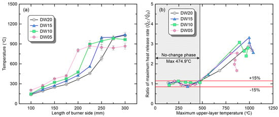
Figure 6.
Comparison of fire phenomena based on upper-layer temperature under various ventilation conditions: (a) maximum upper-layer temperature; (b) ratio of maximum-heat-release rate.
The upper-layer temperature can provide useful information about changes in the thermal environment within the compartment according to the ventilation condition. However, the amount of fuel supply from the burner can vary dominantly due to the incident heat flux from the smoke layer and walls rather than the upper-layer temperature. Accordingly, Figure 7 presents a comparison of the maximum-incident-heat flux measured on the compartment floor and the based on it. Owing to a measurement error of the plate thermometer (PT-D) installed at the back of the compartment, only the measurements of the front (PT-B) were used. As shown in Figure 7a, a comparison of the maximum-incident-heat fluxes with respect to the burner size revealed a trend similar to that of the upper-layer temperature. Specifically, in the range corresponding to the ‘no-change’ phase (L100~L175), the incident heat flux was measured to be higher as the door width became narrower even for the same burner size. Afterwards, as the burner size expands, a transition to the ‘promoted’ phase occurs, and this transition occurs in smaller burners as the opening width becomes narrower. The trend is clearly shown in Figure 7b, where is expressed as a function of the maximum-incident-heat flux. Under the condition where the incident heat flux was <17.6 kW/m2, the change in did not exceed ±15%. Furthermore, it can be seen that the wider the opening width, the greater the number of burners within this range. These results are consistent with the previous analysis based on the upper-layer temperature. In conclusion, the reason why the critical at which the transition to the ‘promoted’ phase occurs depending on the opening shape is different is because heat loss due to discharge flow changes the thermal environment inside the compartment.
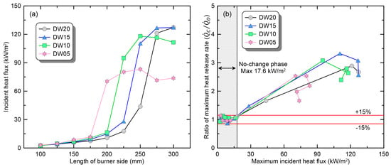
Figure 7.
Comparison of fire phenomena based on heat flux under various ventilation conditions: (a) maximum-incident-heat flux at the bottom; (b) ratio of maximum-heat-release rate.
Figure 8 shows the selection criterion and analysis results of experimental conditions corresponding to the ‘boiling’ phase. As defined in Figure 3c, in the ‘boiling’ phase, there was a transition to the under-ventilated condition, with flame ejection through the opening. Considering this, Figure 8a presents photographs of the instantaneous flame under the conditions in which the first ejecting flame occurred for each opening. A comparison of the photographs indicated that with a wider opening, the ejecting flame was generated from a larger burner. The reason is that as the door width increases, the amount of air inflow increases and a greater fuel supply is required to convert to the under-ventilated condition. In this regard, there were also significant differences in the volume of the ejecting flame due to the differences in the fuel supply that generated ejecting flames. Additionally, it was confirmed that all conditions in which burners larger than those shown in Figure 8a burn under each ventilation condition correspond to the ‘boiling’ phase. Figure 8b shows the behavior of according to in the ‘boiling’ phase to derive the correlation of maximum HRR. In the ‘boiling’ phase, exhibited similar behavior (a linear reduction), regardless of the opening shape, in contrast to the ‘no-change’ phase. In the classification of the ventilation conditions, the ‘boiling’ phase corresponds to the UVF condition, and the UVF phenomenon is dominated by the ventilation condition. Consequently, the behavior of the ‘boiling’ phase depends on , and the correlation is defined using Equation (6). In conclusion, the maximum HRR according to the ventilation conditions of the compartment can be predicted by multiplying maximum HRR in an open environment by the obtained using Equation (6).
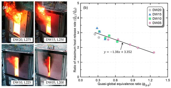
Figure 8.
Comparison of fire phenomena during the boiling phase and the correlation of the maximum-heat-release rate: (a) photos of instantaneous flame; (b) correlation of the maximum-heat-release rate.
To evaluate the applicability of the derived correlations, Figure 9 directly compares the measured maximum HRR with the predicted maximum HRR and presents the relative error () of the predicted values. As mentioned earlier, the ‘promoted’ phase was observed in only two experiments among all conditions, and was excluded from evaluation because no correlation was derived. Figure 9a shows the predicted maximum HRR as a function of the measured maximum HRR. The values were very similar, within the error range of ±15% for all the experimental conditions. To quantify the accuracy of the correlation, the relative error of the predicted value to the measured value is presented in Figure 9b. For all the conditions, the relative errors were <15% (solid line), and the maximum relative error was 14.9%. This suggests that the proposed correlation can be used to predict changes in the maximum HRR of thermoplastics according to the combustion environment.
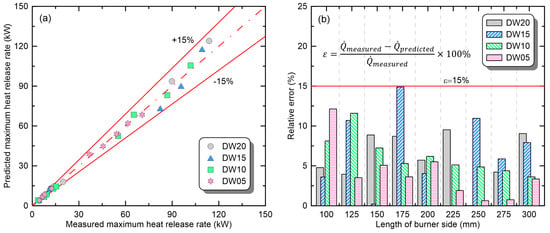
Figure 9.
Applicability evaluation of the correlations for predicting maximum-heat-release rate of compartment fires: (a) direct comparison of measured and predicted values; (b) relative error.
4. Conclusions
Due to a lack of experimental data for various buildings and combustibles, inappropriate fire source information may be input into fire-risk assessments using fire simulations. To prevent the compromise of reliability in fire-risk assessments due to this, an experimental study was conducted using the PMMA. Fire experiments with nine burners of varying sizes were conducted in open environments and compartment environments with different opening configurations. The variations in the maximum-heat-release rate under different ventilation conditions were examined, and correlations were established. The major results are as follows.
(1) Compared with the fire phenomenon in the open environment, the compartment fire phenomena was classified into three phases—‘no-change’, ‘promoted,’ and ‘boiling’—depending on the maximum HRR, flame length, and the generation of ejecting flames. Furthermore, the fire growth rate and maximum HRR of compartment fires according to the phased fire phenomena can be increased by a factor ranging from 3.5 to 50 compared with the open environment.
(2) In the ‘no-change’ phase, the reduction in ventilation area creates a virtuous cycle of fire growth due to a rapid rise in temperature inside the compartment and an increase in thermal feedback. On the other hand, it was confirmed that when the burner size continued to increase, fire growth was inhibited due to easy transition to the under-ventilated condition. As a result, in the ‘boiling’ phase, even though the same burner burned, the maximum-heat-release rate and the volume of the ejected flame tended to decrease as the ventilation area became narrower.
(3) Correlations were proposed for predicting the maximum HRR of the compartment fire according to experimental results obtained in an open environment. Separate correlations were proposed for the ‘no-change’ and ‘boiling’ phases among the three categories of fire phenomena. Additionally, the correlations provided predicted values of the maximum-heat-release rate with errors of less than ±15% for all experimental conditions considered in this study.
This study provides a basic methodology for predicting compartment fire phenomena, which undergo various changes depending on the compartment shape and ventilation conditions. These results could serve as foundational information for more accurately assessing the risks of building fires and devising corresponding measures. However, for these research findings to be practically applied, numerous follow-up studies are required. Firstly, additional experiments are required to examine the clear boundaries for the transitions between the proposed stages in this study. Additionally, it is also necessary to check whether the proposed correlation is applicable to other solid or liquid combustibles. Follow-up studies will be conducted to overcome the limitations of this study and to expand the application scope of the proposed correlations.
Author Contributions
Conceptualization, H.-S.Y.; Validation, H.-S.Y.; formal analysis, H.-S.Y.; investigation, H.-S.Y.; data curation, H.-S.Y.; writing—original draft, H.-S.Y.; visualization H.-S.Y.; methodology, C.-H.H.; resources, C.-H.H.; writing—review and editing, C.-H.H.; supervision, C.-H.H.; project administration, C.-H.H.; funding acquisition, C.-H.H. All authors have read and agreed to the published version of the manuscript.
Funding
This research was funded by National Fire Agency R&D Program (Grant number 20016433), and the Korea Agency for Infrastructure Technology Advancement (KAIA) grant funded by the Ministry of Land, Infrastructure and Transport (Grant RS-2022-00156237).
Institutional Review Board Statement
Not applicable.
Informed Consent Statement
Not applicable.
Data Availability Statement
The data used to support the findings of this study are available from the corresponding author upon request.
Conflicts of Interest
The authors declare no conflicts of interest.
References
- McGrattan, K.; McDermott, C.; Weinschernk, C.; Overholt, K.; Hostikka, S.; Floyd, J. Fire Dynamics Simulator, User’s Guide; NIST: Gaithersburg, MD, USA, 2017.
- McGrattan, K. Verification and Validation of Selected Fire Models for Nuclear Power Plant Applications; Fire Dynamics Simulator (FDS); U.S. Nuclear Regulatory Commission: Washington, DC, USA; Electric Power Research Institute (EPRI): Palo Alto, CA, USA, 2007; Volume 7.
- Gottuk, D.; Mealy, C.; Floyd, J. Smoke Transport and FDS Validation. In Proceedings of the 9th International Symposium Fire Safety Sciences, University of Karlsruhe, Karlsruhe, Germany, 21–26 September 2008. [Google Scholar]
- Wahlqvist, J.; Hees, P.V. Validation of FDS for large-scale well-confined mechanically ventilated Fire scenarios with emphasis on predicting ventilation system behavior. Fire Saf. J. 2013, 62, 102–114. [Google Scholar] [CrossRef]
- Brohez, S.; Caravita, I. Fire induced pressure in airthigh houses: Experiments and FDS validation. Fire Saf. J. 2020, 114, 103008. [Google Scholar] [CrossRef]
- Lee, J.; Kim, B.; Lee, S.; Shin, W.G. Validation of the fire dynamics simulator (FDS) model for fire scenarios with two liquid pool fires in multiple compartments. Fire Saf. J. 2023, 141, 103892. [Google Scholar] [CrossRef]
- Park, W.H. Optimization of fire-related properties in layered structures. J. Mech. Sci. Technol. 2019, 33, 3831–3840. [Google Scholar] [CrossRef]
- Tyas, D.; Bagshow, D.; Plummer, J.; Nyogeri, L. Modelling the heat release rate of PRISME experimental cable fires in a confined, ventilation controlled, environment using FLASH-CAT and FDS. Fire Saf. J. 2023, 139, 103828. [Google Scholar] [CrossRef]
- Zhao, Q.; Beji, T.; Merci, B. Application of FDS to Under-Ventilated Enclosure Fires with External flaming. Fire Technol. 2016, 52, 2117–2142. [Google Scholar] [CrossRef]
- Betting, B.; Varea, E.; Gobin, C.; Godard, G.; Lecordier, B.; Patte-Rouland, B. Experimental and numerical studies of smoke dynamics in a compartment fire. Fire Saf. J. 2019, 108, 102855. [Google Scholar] [CrossRef]
- Jahn, W.; Rein, G.; Torero, J.L. The Effect of Model Parameters on the Simulation of Fire Dynamics. In Proceedings of the 9th International Symposium Fire Safety Sciences, University of Karlsruhe, Karlsruhe, Germany, 21–26 September 2008. [Google Scholar]
- Yung, D. Small-scale Compartment Fire Experiments with PMMA Cribs. Fire Saf. J. 1991, 17, 301–313. [Google Scholar] [CrossRef]
- Hadjisophocleous, G.; Zalok, E. Development of Design Fires for Performance-Based Fire Safety Designs, In Proceedings of 9th International Symposium Fire Safety Sciences, University of Karlsruhe, Germany, 21–26 September 2008.
- Ministry of Business, Innovation & Employment. CV/M2 Verification Method: Framework for Fire Safety Design—Fore New Zealand Building Code Clauses C1-C6 Protection from Fire; Ministry of Business, Innovation & Employment: Wellington, New Zealand, 2014.
- Fleischmann, C. Defining the Heat Release Rate per Unit Area for use in Fire Safety Engineering Analysis. In Proceedings of the 10th Asia-Oceania Symposium on Fire Science and Technology, Tsukuba, Japan, 5–7 October 2015. [Google Scholar]
- Guillaume, E.; Didieux, F.; Thiry, A.; Bellivier, A. Real-scale fire tests of one bedroom apartments with regard to tenability assessment. Fire Saf. J. 2014, 70, 81–97. [Google Scholar] [CrossRef]
- Johansson, N.; Svensson, S.; Van Hees, P. A Study of Reproducibility of a Full-Scale Multi-Room Compartment Fire Experiment. Fire Technol. 2015, 51, 645–665. [Google Scholar] [CrossRef]
- Tang, Z.; Wang, Z.; Chen, R.; Fang, Z.; Mou, Y.; Wei, J.; Zhang, C.; Wang, Z.; Femg, D.; Zhang, M.; et al. Experiment study of fire characteristics in full-scale bedrooms under different vents and sprinkler conditions. Fire Saf. J. 2023, 141, 103927. [Google Scholar] [CrossRef]
- Yun, H.S.; Nam, D.G.; Hwang, C.H. A numerical Study on the Effect of Volume Change in a Closed Compartment on Maximum Heat Release Rate. Fire Sci. Eng. 2017, 31, 19–27. [Google Scholar] [CrossRef]
- Yun, H.S.; Hwang, C.H. A Correlation Study for the Prediction of the Maximum Heat Release Rate in Closed-Compartments of Various Configurations. Fire Sci. Eng. 2018, 32, 16–23. [Google Scholar] [CrossRef]
- Yun, H.S.; Hwang, C.H. Quantitative Comparison of Maximum Heat Release Rates of Wood Combustibles in Open and Compartment Fire Environments. Fire Sci. Eng. 2023, 37, 43–50. [Google Scholar] [CrossRef]
- Yun, H.S.; Hwang, C.H. Effects of Quantity and Arrangement of a Flame-Retardant Cable on Burning Characteristics in Open and Compartment Environments. Energies 2023, 16, 845. [Google Scholar] [CrossRef]
- Yun, H.S.; Hwang, C.H. Changes in Fire Characteristics of Liquid Fuel depending on Ventilation Conditions in a Reduced-Scale Compartment. Fire Sci. Eng. 2023, 37, 1–10. [Google Scholar] [CrossRef]
- Yun, H.S.; Mun, S.Y.; Hwang, C.H. The Sinkhole Phenomenon-Changes in Compartment Fire Characteristics Due to Incomplete Combustion before Flame Ejection. Appl. Sci. 2022, 12, 12278. [Google Scholar] [CrossRef]
- Pitts, W.M. The global equivalence ratio concept and the formation mechanisms of carbon monoxide in enclosure fires. Prog. Energy Combust. Sci. 1995, 21, 197–237. [Google Scholar] [CrossRef]
- Gottuk, D.T.; Roby, R.J.; Peatross, M.J.; Beyler, C.L. Carbon monoxide production in compartment fires. J. Fire Protect. Eng. 1992, 4, 133–150. [Google Scholar] [CrossRef]
- Ko, G.H.; Hamins, A.; Bundy, M.; Johnsson, E.L.; Kim, S.C.; Lenhert, D.B. Mixture fraction analysis of combustion products in the upper layer of reduced-scale compartment fires. Combust. Flame 2009, 156, 467–476. [Google Scholar] [CrossRef]
- Hamins, A.; McGrattan, K. Verification and Validation of Selected Fire Models for Nuclear Power Plant Applications; U.S. Nuclear Regulatory Commission: Washington, DC, USA; Electric Power Research Institute (EPRI): Palo Alto, CA, USA, 2007; Volume 2: Experimental Uncertainty.
- Karlsson, B.; Quintiere, J. Enclosure Fire Dynamics; CRC Press: Boca Raton, FL, USA, 1999; Chapter 6. [Google Scholar]
Disclaimer/Publisher’s Note: The statements, opinions and data contained in all publications are solely those of the individual author(s) and contributor(s) and not of MDPI and/or the editor(s). MDPI and/or the editor(s) disclaim responsibility for any injury to people or property resulting from any ideas, methods, instructions or products referred to in the content. |
© 2024 by the authors. Licensee MDPI, Basel, Switzerland. This article is an open access article distributed under the terms and conditions of the Creative Commons Attribution (CC BY) license (https://creativecommons.org/licenses/by/4.0/).