Abstract
The overpressure characteristics of gasoline explosions in multi-branch pipes are caused by various factors, with flame velocity as a particularly significant determinant. Overlooking the impact of turbulent flow in the branch pipes can induce a significant discrepancy in the outcome when using laminar flame velocity to determine the maximum rate of overpressure rise. To quantify the impact of turbulent flame velocity on the rate of overpressure rise in the gasoline explosions within branch pipes, the laminar flame velocity was replaced with its turbulent counterpart. Additionally, modifications to the formula for calculating the maximum overpressure rise rate were implemented. Then, experimental data of peak explosion overpressure and overpressure rise rate under different numbers of branches were obtained. Finally, the empirical data were inputted into the modified formula to determine the maximum rate of overpressure rise, thus enabling the calculation of the turbulent flame velocity across varying numbers of branches. The findings reveal a positive correlation between the number of branches and the turbulent flame velocity during tube explosions. When the number of branch pipes increased from 0 to 4, the turbulent flame velocity was found to range from 8.29 to 13.39 m/s. The increase in the number of branches did not consistently enhance the turbulent flame velocity. As the number of branches increased from zero to three, the turbulent flame velocity rose accordingly. Differently, as the number of branches exceeds three, the turbulent flame velocity exhibits fluctuations and peaks at a level approximately 1.8 times higher. The research method of this paper can provide a reference for estimating the turbulent flame velocity in the combustion process of flammable gas explosions in multi-branch tunnels.
1. Introduction
Explosions of combustible gas are a major hazard in both industrial production and daily life. Of particular concern is the explosion of chemical gases, which has the potential to cause severe casualties and property damage. Therefore, explosions of this type have attracted considerable attention. To evaluate the damage caused by gas explosions and improve the design of explosion-proof vessels, it is often necessary to assess various parameters, including maximum explosion pressure, maximum pressure rise rate, and gas explosion index KG [1,2,3]. These parameters are widely used in academic and industrial settings. Nevertheless, the aforementioned parameters are significantly affected by the initial conditions of combustion for the combustible mixture, including but not limited to the initial temperature [4], initial pressure [5,6], container size [7] and geometry [8], ignition energy [9] and position [10], and turbulence level [11]. Bauwens et al. [12] found that the increase in turbulence caused by obstacles significantly enhanced the maximum flame area, combustion rate, and external explosion overpressure. Arisova et al. [13] conducted research on the pipe explosion pressure and flame velocity of branch tunnel discharge; their results indicated that the turbulence caused by the branch tunnel can cause multiple different pressure peaks in explosion overpressure and that the flame velocity increases with the distance between the branch tunnel and the ignition position. Similar research conclusions were also found in a relevant study by Ponizy and Henneton [14]. Almerinda [15] analyzed the effect of ignition energy and ignition source on the deflagration index and found that the deflagration index is independent of ignition energy and mainly depends on turbulence. As indicated by Yan Ming [16] and Wang Kai [17], the initial turbulence level is largely affected by the size and shape of the container.
In the context of subterranean oil caverns, oil pipes, and domestic natural gas pipes characterized by a multi-branch configuration, the flame dynamics and overpressure characteristics exhibited by the explosion of flammable gas differ from those observed in a conventional confined space or container during a gas explosion.
Numerous studies [4,18] establish a close correlation between the behavior of explosion flames and the overpressure characteristics of combustible gas in a branch-structured tunnel. Moreover, the intensity of explosions in this context is higher compared to that of gasoline in a confined space. A significant contributor to this phenomenon is a multi-branch structure, which enables the propagation and development of flames and pressure waves in multiple-branch tunnels. Consequently, multiple distinct flame fronts develop, significantly increasing both the total area of flame and the rate of heat release. In turn, the presence of a branch tunnel leads to multiple interacting pressure waves, which further complicates the distribution and evolution of the pressure field within a confined space. In the course of an explosion, a branch-structured tunnel has a significant impact on the turbulence across the flow field. The explosion theory suggests that within a confined container, a positive feedback mechanism exists, involving turbulence, flame velocity, and overpressure [4]. Therefore, a significant characteristic shown by the explosion of flammable gas within a tunnel comprising a complex network of branches is the close correlation between turbulence, flame, and pressure wave phenomena. Recent incidents caused by explosions in a confined space after the structural failure of gasoline branches with great loss of life [18] serve as evidence of the aforementioned findings.
Gas explosions can be exacerbated by the factors that increase turbulence in the gas flow within pipes, which causes a rising level of explosion-induced overpressure. There have been many studies on the impact of turbulence on explosion intensity within tubes. Li et al. [19] conducted an analysis of the different characteristics of flame variation and overpressure in T-shaped pipe branches. This analysis combined experimental investigation and numerical simulation. The findings of this study confirm the argument that intensifying flame folding and turbulence in the T-shaped pipe branches leads to an increase in explosion pressure. The study by Wang Hua et al. [20] examined the impact of initial turbulence on methane–air explosions. According to the experimental results, initial turbulence contributes to an increase in both the maximum explosion pressure and the maximum rate of pressure rise. Additionally, the time to reach the maximum explosion pressure was shortened and the presence of initial turbulence enhanced the explosive intensity and destructive power of the methane–air mixture. According to the research findings presented by Xie Yiyue [21], the explosion range for combustible gas (vapor) is narrower in a turbulent state than in a macroscopic static state. Turbulence induces the folding of the flame front, which leads to an indistinct boundary and a notable increase in flame propagation velocity. The study by Jian Congguang and Lin Baiquan [22] indicated the significant impact of the sudden change in pipe area on turbulence during gas explosions. Abrupt increases or decreases in the cross-sectional area of the pipe give rise to additional turbulence.
The objective of this study is to establish a correlation between the turbulent flame velocity and the maximum rate of overpressure rise through a combination of theoretical analysis and experimentation. On this basis, the turbulent flame velocity of gasoline explosions in enclosed containers will be determined. The findings of this study are expected to support the assessment of damage caused by gasoline explosions, the design of explosion-proof containers, and the implementation of safety measures for pipes.
2. Theoretical Estimation Method for Turbulent Flame Velocity
According to the research conclusions of Pu [23], Dahoe [24], and F. Cammarota et al. [25], the formula for calculating the rise rate of the maximum explosive overpressure of combustible gas in a vertical cylindrical vessel is
where is the maximum flame front area, m2; is volume of explosive vessel, m3; is the laminar flame velocity, m/s; is the peak explosion pressure, Pa; is the initial pressure, Pa; is the gas adiabatic index; and is the peak boost rate, Pa/s.
The above formula shows that the maximum overpressure rise rate is related to the shape and size of the container (i.e., AV and V), is proportional to the laminar flame velocity, and is related to the peak overpressure and initial pressure. Wang et al. [17] and Li et al. [19] found that a gas explosion experiment in an over-branching-structure vessel intensified the explosive gas turbulence in the tube, thus leading to an increase in the explosion overpressure rise rate. However, Formula (1) does not consider the influence of turbulence level on the rate of overpressure rise. In fact, due to the short duration of laminar flow in the process of a premixed gas explosion, most of the time is in a turbulent state, and the use of laminar flame velocity to describe the impact on the rate of overpressure rise is bound to bring a large deviation. Therefore, it is necessary to rewrite Formula (1) by replacing laminar flame velocity with turbulent flame velocity. Based on this, Formula (1) is rewritten as follows:
where is denotes the turbulent flame velocity, m/s. According to Formula (2), it can be calculated using the following formula:
where is the explosion vessel volume, m3; is peak explosion pressure, Pa; is initial pressure, Pa; and is peak pressure rise rate, Pa/s. These parameters can be determined using experimental data, while the maximum flame front area and gas adiabatic index can only be obtained via theoretical calculation. Therefore, through Formula (3), the turbulent flame velocity in the gasoline–air explosion process of pipes with different multi-branch structures can be calculated, and the relationship between the flame velocity of turbulence and parameters such as the number and length of branch pipes can be further discussed.
3. Experimental Methods and Data
3.1. Experimental Devices and Methods
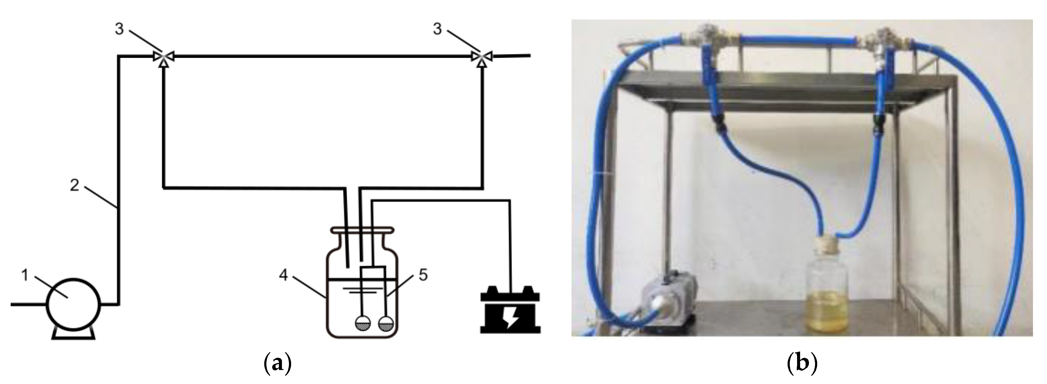
In this study, the experimental set-up involved a combined test bench, a dynamic signal acquisition system, a gasoline atomizing circulation system, a volume fraction test system, and an ignition system, as illustrated in Figure 1.
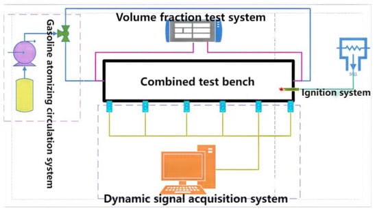
Figure 1.
Composition of the experimental system.
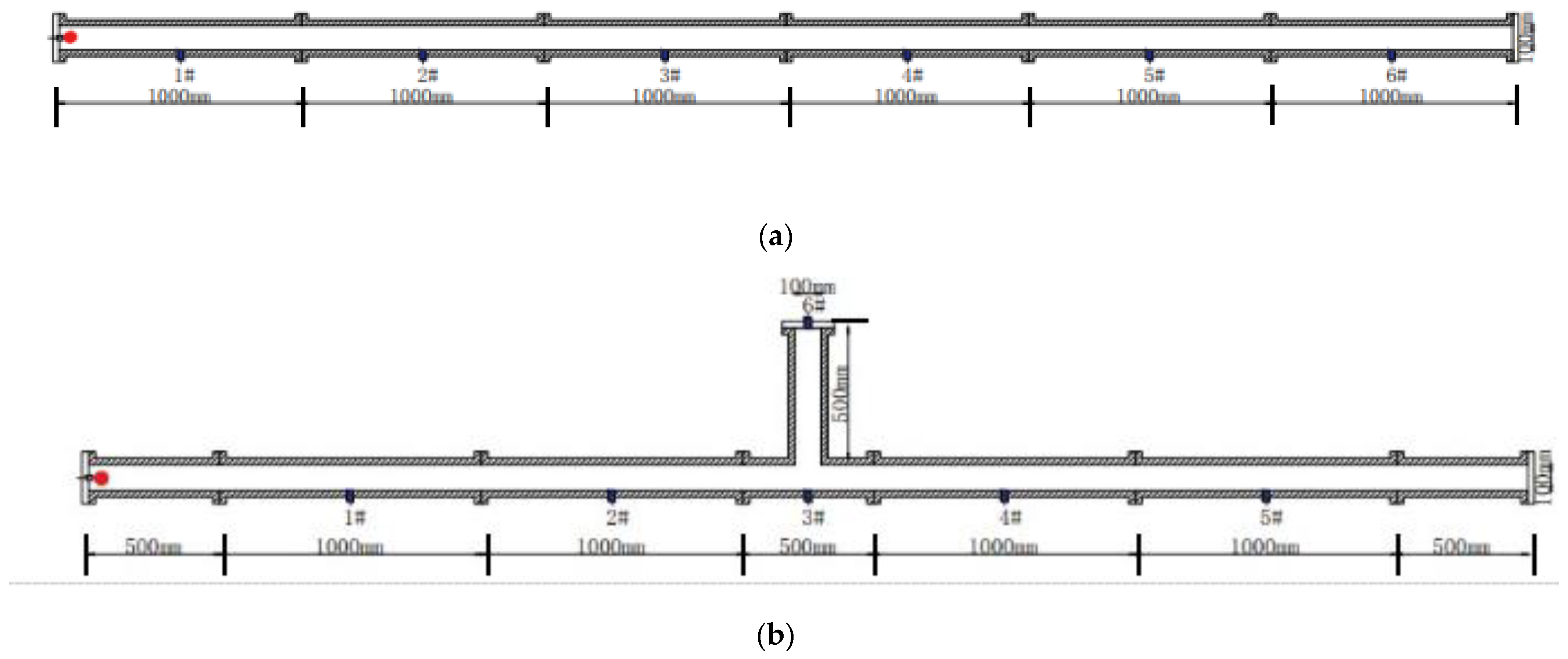
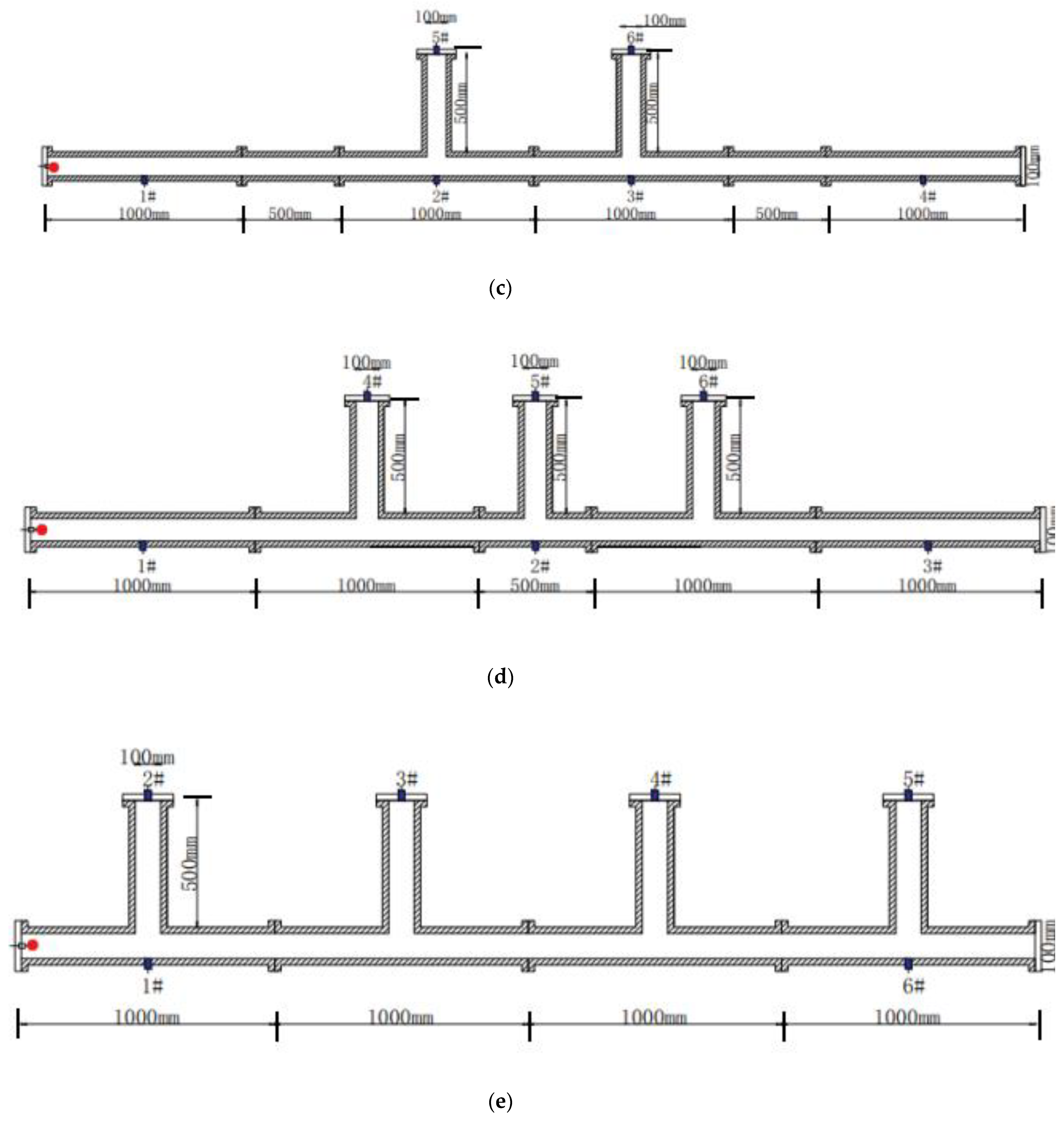
The combined test bench primarily consisted of four steel square pipes in different forms and lengths, including a 0.5 m straight pipe, a 1 m straight pipe, a 0.5 m length straight pipe, a 1 m length straight pipe, a tee composed of a 1 m main pipe and a 0.5 m branch pipe, and a tee composed of a 0.5 m main pipe and a 0.5 m branch pipe. These pipes had a wall thickness of 10 mm and a cross-section size of 0.1 m × 0.1 m, with a round hole opened around the square pipe for pressure sensor installation. According to the experimental requirements, four types of square tubes were assembled through flanges, and five types of test benches with 0, 1, 2, 3, and 4 branches, respectively, were constructed. To maintain a constant total volume of the bench, the total length was set to 6 m. Figure 2 shows the structures and the dimensions of the five test benches.

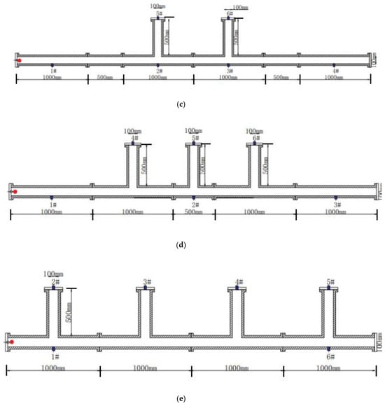
Figure 2.
Scheme of combined test bench and position of transducers (i # pressure transducers). (a) Straight pipe, (b) straight pipe containing 1 branch, (c) straight pipe containing 2 branches, (d) straight pipe containing 3 branches, (e) straight pipe containing 4 branches.
The dynamic signal acquisition system consisted of a high-frequency dynamic pressure sensor and a signal acquisition and analysis system. With six sensors installed on the test platform (as shown in Figure 2), the accuracy level reached 0.25%FS, and the range was 0–1 MPa. During the experiment, pressure data were tested, and the system of dynamic signal acquisition and analysis provided data on pressure changes.
The gasoline atomizing circulation system consisted of an oil storage bottle, a vacuum pump, an ultrasonic atomizer, a pipe, and a three-way ball valve. Gasoline vapor was generated by the ultrasonic atomizer and pumped into the test bench. The volume concentration of oil vapor was measured using an infrared gas concentration tester. After the target concentration was reached, the three-way valve was adjusted for gas circulation to evenly distribute the gasoline in the test bench. Figure 3 shows the system’s structure.
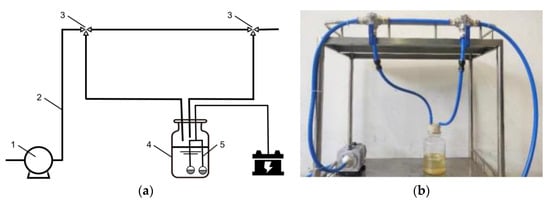
Figure 3.
Gasoline atomizing circulation system. (a) Specific structure: 1. oil storage bottle; 2. pipe; 3. three-way ball valve; 4. oil storage bottle; 5. ultrasonic atomizer. (b) Photo of the gasoline atomizing circulation system.
A high-energy non-interference ignition mode was adopted for the ignition system, with the initial energy of the gasoline explosion provided through a high-energy arc spark.
The initial conditions of the experiment were as follows: the initial temperature was 293 K, the initial pressure was 101 kPa, and the ignition energy was 5 J. No. 92 gasoline was the experimental object; its performance parameters are detailed in Table 1. The explosion characteristics of gasoline are more pronounced within the range of gasoline volume fraction from 1% to 2.7%, with the most evident effects observed between 1.2% and 1.6%. Therefore, the experimental concentration of gasoline was set at 1.2%.

Table 1.
Main properties of the 92 RON unleaded gasoline.
The experiment involved three major parts: gasoline premix, ignition experiment, and data acquisition. In the initial phase of oil–gas mixing, the gasoline–air mixture was injected into the experimental pipe through a gasoline atomization system, with the concentration of gasoline measured simultaneously. Once the required concentration was reached, the gasoline atomization system transitioned into the circulation process and lasted 2 min to ensure a thorough and even mixing of gas and air in the pipe. When the premixed gas was stabilized, the gas circulation system was switched off for 30 s. Subsequently, the control ignition system and the pressure acquisition system were activated simultaneously to collect the relevant experimental data. To ensure objectivity and repeatability, the experiment was conducted three times under the same working conditions, and the average of these experiments was analyzed to examine the change in overpressure load.
3.2. Acquisition of Experimental Data
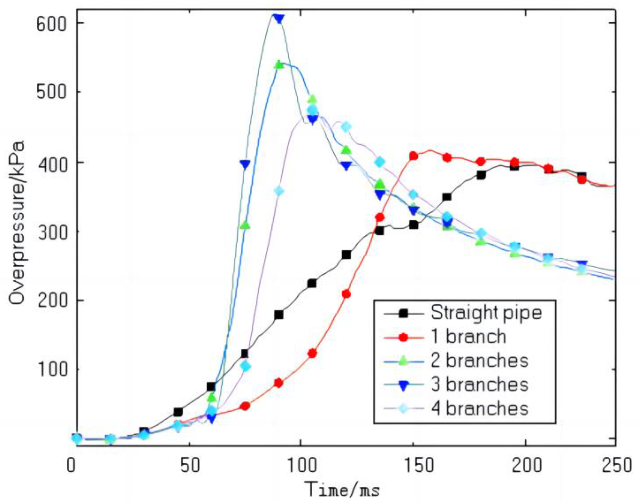
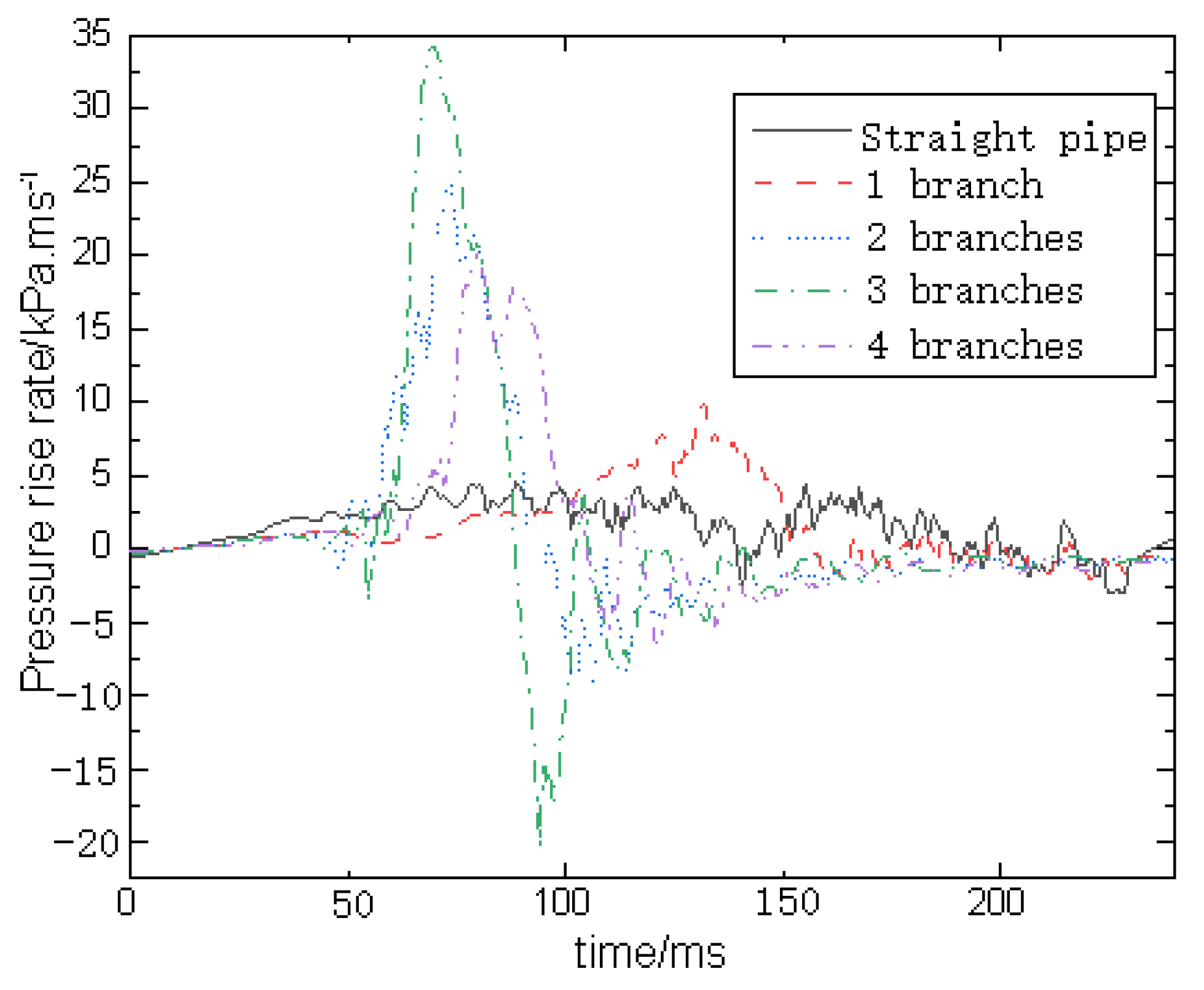
Figure 4 and Figure 5 show the impact of varying branch numbers on the sequence of explosion overpressure and boost rate. Obviously, as the number of branches increases, there is a significant rise in both explosion overpressure and pressure boost rate, suggesting a positive influence of pipe branches on the explosion overpressure. Figure 6 illustrates the variations in peak overpressure, the time at which the peak overpressure is reached, and the pressure boost rate with different branch numbers. Additionally, it is evident that the maximum boost rate is higher when branching occurs. In general, as the number of pipe branches increases, both the peak explosion overpressure and pressure boost rate first increase and then decrease. However, it is worth noting that a larger number of branches is correlated with a more significant positive effect. The use of a branch pipe amplifies such phenomena as diffracting, superposition, and excitation associated with the explosion wave generated by the combustion of gasoline and air.
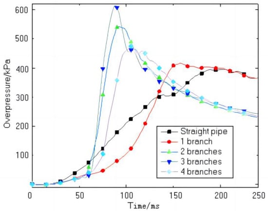
Figure 4.
Curves of explosion overpressure history of gasoline–air mixture with different numbers of branches.
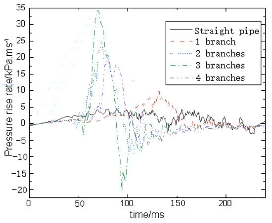
Figure 5.
Comparison of overpressure rising rate time-series curves of different branches.
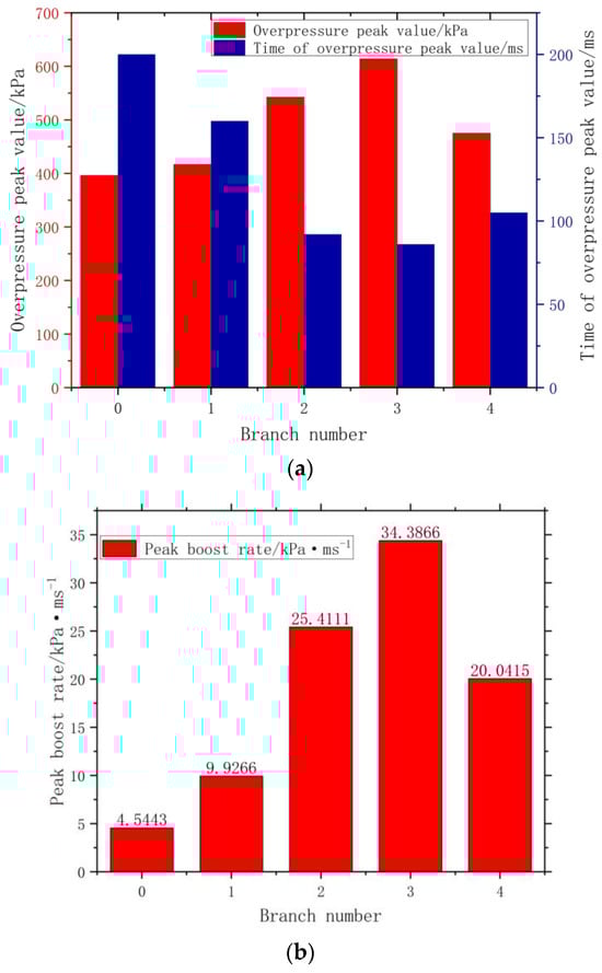
Figure 6.
Peak overpressure and overpressure rising rate of different branches. (a) Peak value and time of overpressure. (b) Peak rate of overpressure rise.
According to Figure 4, Figure 5 and Figure 6, the peak values of overpressure and boost rate can be extracted from the experimental values, as shown in Table 2.
Table 2.
Peak values of overpressure and boost rate under different working conditions.
4. Theoretical Calculation of Other Data
4.1. Maximum Flame Front Area
Christophe et al. [26] pointed out that the progression of gas explosion flame propagation in a narrow confined space can be divided into three typical processes: (1) the formation of a hemispherical flame at the initial ignition stage; (2) the axial stretching of the flame, which forms a finger flame; and (3) the deformation of the flame surface into a tulip flame. An analysis of these stages allows for the determination of the maximum flame front area. In the first stage, the premixed combustible mixture is ignited by an electric spark from the ignition electrode, and the flame zone extends in all directions. At this time, the flame range is small, and the wall influence is negligible. An idealized flame front in a pipe has the shape of a half sphere, and the area is calculated according to
In the second stage, with the axial stretching of flame, the flame front became a finger, referred to as the finger phase. At this point, the flame front maintains a basic half-spherical shape along the axial forefront, and in the radial transmission, cold collisions occur as the flame contacts the wall surface. If the container shape remains constant, the maximum flame front area at this stage is identical to that of the first stage. However, in the case of an experimental vessel configured as a multi-branch pipe, an increase in channel area leads to a larger flame area when the flame propagates to the branch. Therefore, the relationship between the maximum flame front area and the number of branches can be approximated.
In the third stage, with the continued spread of flame, due to the return air flow instability and fluid mechanics, the influence of the flame front, initially outward spherical, gradually transforms into a flattened shape with a sagging center. This transformation occurs with a short duration, based on [5], when the explosion total time reached 1.29 times the wall time fireside, a twisted flame occurred and formed a tulip flame. As can be seen from Figure 4, both the explosion overpressure and the pressure boost rate reach their peaks in a very short duration of the explosion. Therefore, in the pipe, the tulip flame exerts little influence on the key parameters of explosion and can be ignored, and the maximum flame front area of this stage is the same as that of the first stage. The above analysis is for a straight pipe; however, because the experimental vessel is a multi-branch pipe, the increase in the channel area will lead to an increase in the flame area when the flame propagates to the branch. When the flame propagates to the branch pipe, the area of the flame front will approximately double. Therefore, for a single branch pipe (Figure 2b), the maximum flame front area is
For pipes with two, three, and four branches (Figure 2c–e), the distance between adjacent branch pipes is greater than or equal to the length of each branch pipe. Therefore, when the flame front propagates to the next branch pipe, the flame in the previous branch pipe has already spread to the bottom of the branch pipe and been extinguished. It can be approximated that when there are two, three, or four branches, the maximum flame area throughout the explosion process is still twice the maximum flame area of a straight pipe (Figure 2a), which is equal to the maximum flame area when there is one branch, at 0.126 m2.
In summary, for a straight pipe without any branching, the maximum flame front area is 0.063 m2. When there are one, two, three, or four branch pipes, the maximum flame area is always 0.126 m2.
4.2. Laminar Flame Velocity and Gas Adiabatic Index
Metghalhi and Kech [27] carried out a series of experiments in the combustion chambers of reciprocating internal combustion engines and gas turbines and determined the formula for calculating laminar flame propagation velocity of fuel–air mixture through experiments:
where the subscript ref is the value of the reference state (101 kPa, 293 K), γ is the adiabatic index, and β is the pressure index. When the temperature for the unburned mixture in Formula (5), the laminar flame velocity can be simplified as
where is the chemical equivalent ratio of combustible gas. , , and are constants determined by the type of combustible gas and are given in Table 3.
Table 3.
of different combustible gases.
In this study, No. 92 gasoline was selected in the experiment, and the volume concentration of gasoline–air was 1.2%. For the convenience of calculation, No. 92 gasoline was replaced with isooctane. According to Li’s study [6], the adiabatic index and pressure index of gas are functions of the chemical equivalent ratio of combustible gas, expressed as
Zhang Peili et al. [28] analyzed the relationship between the equivalent ratio of gasoline combustion and volume fraction in the literature. According to the analysis conclusion of the literature, the chemical reaction formula of isooctane combustion in air is as follows:
The stoichiometric air–fuel ratio is:
And
According to the gas state formula, under the same temperature and pressure conditions,
According to the above formula, when the oil/gas volume fraction Yfuel = 0.012, the oil/gas chemical equivalent ratio is
The gas adiabatic index and pressure index are
According to Table 2, the laminar flame velocity of isooctane can be calculated using Formula (6):
5. Turbulent Flame Velocity Estimation Results and Discussion
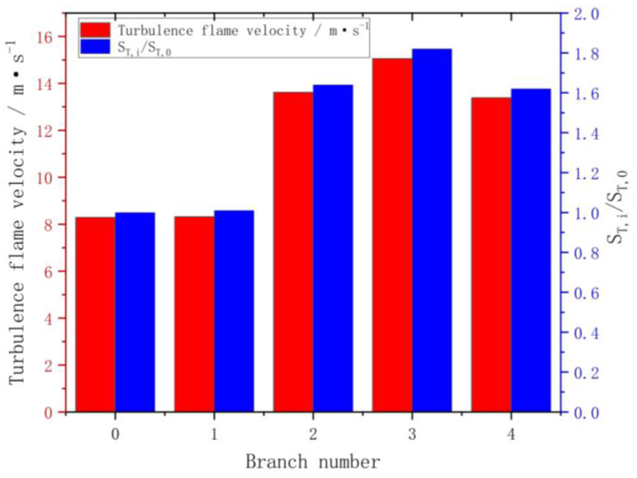
By substituting the experimental data and theoretical calculation data obtained under the above working conditions into Formula (3), the turbulent flame velocity can be calculated in different working conditions. The calculation results are shown in Table 3, where the branch number of 0 represents the working condition of the straight vessel.
Table 4.
Turbulence factors under different conditions.

Figure 7.
Scatter diagrams of turbulent flame velocity under different numbers of branches.
The analysis shown in Figure 7 reveals a notable increase in turbulent flame velocity compared to the laminar flame. Additionally, the turbulent flame exhibits exponential growth during the explosion as the number of branches increases. When the number of branches is one, the turbulent flame velocity is basically equivalent to that of the straight tube as the overpressure rate and flame area are synchronous. However, as the number of branches continues to rise to three, the influence of the overpressure rate exceeds that of the flame area, with a substantial increase in turbulent flame velocity of up to 1.8 times. However, beyond the number of three branches, the turbulent flame velocity begins to decline. Existing literature examines the correlation between flame velocity in gasoline explosions across multiple branches and the number of branches. According to these studies, an increase in the number of branches does not necessarily result in a proportional increase in flame velocity [29]. Instead, the flame velocity decreases when the number of branch tunnels exceeds a specific threshold.
The escalation in turbulence during the branch pipe explosion process is mainly attributed to the propagation of the flame into the branch. At this stage, the flame front undergoes serious creasing, bending, and deformation, which results in an expanded burning area of gas flame, which, in turn, enhances the entrainment effect of mixed gas and increases the combustion reaction rate, accelerating the active substances’ involvement in combustion reaction and enhancing the heat transport rate. As a result, the flame travels at a faster velocity, giving rise to a rise in the intensity of the compression wave generated by the explosion. Meanwhile, the precursor shock wave effectively compresses and preheats the unburned gas in front of the flame, causing a significant disturbance in the airflow. This disturbance contributes to an increased gradient in the flow field and further amplifies the combustion rate and turbulent kinetic energy. From the perspective of hydrodynamics, as the number of branches increases from 0 to 3, the increase in the turbulent flame velocity caused by increased turbulence is greater than the decrease in the turbulent flame velocity caused by heat loss from the flame to the pipe wall. Therefore, the overall effect is an increase in the turbulent flame velocity. However, when the number of branch tunnels becomes four, the increase in the turbulent flame velocity caused by increased turbulence is less than the decrease in flame velocity caused by heat loss from the flame to the pipe wall. As a result, the overall effect is a decrease in turbulent flame velocity. This may be the primary reason for the observed decrease in the turbulent flame velocity when the number of branches reaches four, as shown in Figure 7.
6. Conclusions
In order to quantitatively estimate the turbulent flame velocity of a gasoline vapor explosion in a multi-branch pipe, a formula that can quantitatively calculate the turbulent flame velocity was first obtained through theoretical analysis, and then other overpressure parameters were obtained through experiments. Finally, the turbulent flame velocity of the gasoline vapor explosion process in a multi-branch pipe was quantitatively calculated and analyzed. The main conclusions of this present paper can be summarized as follows:
- The current formula for the maximum overpressure rise rate does not take into account the influence of turbulence, which inevitably leads to deviation when this formula is applied to multi-branch-structured pipe. Considering the influence of turbulence, it is feasible to estimate the turbulent flame velocity of explosions in multi-branch pipes by modifying the formula.
- Compared with straight pipelines, the turbulent flame velocities of explosions in pipes with one, two, three, and four branches are 1.01, 1.64, 1.82, and 1.62 times higher than those in a straight pipe.
- The turbulent flame velocity increases from 8.29 to 15.06 m/s as the number of branch pipes increases from 0 to 3. However, an increase in the number of branch pipes does not always lead to an increase in turbulent flame velocity. When the number of branches increased from three to four, the turbulent flame velocity decreased from 15.06 to 13.39 m/s.
Notably, the turbulent flame velocity determined in this study represents the approximate turbulent flame velocity in a multi-branch pipe during the gasoline–air explosion process. The occurrence of complex structural pipe explosions caused by overpressure during the gasoline–air process is influenced by various factors, including the rate of heat release from fire and the rate of heat loss from solid boundaries. Consequently, it is necessary to conduct a thorough evaluation of the collective impact of these factors on the characteristics of overpressure. Despite the challenges in quantifying the velocity of turbulent flames during gasoline–air explosions within an enclosed container, the research methodology and findings presented in this paper remain useful for investigations into the overpressure characteristics of gas explosions in enclosed containers.
Author Contributions
Writing-original draft, K.L.; Project administration, P.Z.; Methodology, J.D.; Software, C.Y.; Data curation, S.X. and T.S. All authors have read and agreed to the published version of the manuscript.
Funding
This research was funded by the Science and Technology Research Program of Chongqing Municipal Education Commission (No. KJZD-M202112901 and KJZD-M202212901), Natural Science Foundation of China (No. 52272338), Natural Science Foundation of Chongqing (CSTB2023NSCQ-MSX0127), Technological Innovation and Application Development Project of Chongqing (2023TIAD-KPX0113), Chongqing Graduate Scientific Research Innovation Project (No. CYS21527), Natural Science Foundation of China (52302422 and 52272338), a Major Project of the Science and Technology Research Program of the Chongqing Education Commission of China (KJZD-M202212901).
Institutional Review Board Statement
Not applicable.
Informed Consent Statement
Not applicable.
Data Availability Statement
The data used to support the findings of this study are available from the corresponding authors upon request.
Conflicts of Interest
The authors declare no conflicts of interest.
References
- Jiang, X.S.; Zhou, L.; Cai, Y.X.; Zhou, D.L.; Chen, R.; Qin, X.Z. Explosion suppression experiment of oil storage vessel based on porous explosion suppression materials. Oil Gas Storage Transp. 2023, 42, 1158–1165. [Google Scholar]
- Zhang, B.Y.; Cui, J.R. Experimental study on explosion propagation barrier properties of metal foamed with different ex-plosion surface structures for methane gas. Explos. Shock. Waves 2023, 43, 168–178. [Google Scholar]
- Liang, H.; Wang, T.; Luo, Z.; Wang, X.; Kang, X.; Deng, J. Risk Assessment of Liquefied Petroleum Gas Explosion in a Limited Space. ACS Omega 2021, 38, 24683–24692. [Google Scholar] [CrossRef]
- Gao, N. Effect of Initial Temperature on Free Radicals of Gas Explosion in Restricted Space. Adv. Mater. Res. 2013, 2657, 798–799. [Google Scholar] [CrossRef]
- Cui, Y.H.; Jiang, J.C.; Yu, Y.; Zhang, Q.W. Initial Pressure Influence on Explosion Pressures of Methane-Air Deflagrations in Linked Vessels. Adv. Mater.Res. 2014, 3187, 936. [Google Scholar] [CrossRef]
- Li, Y.; Xu, H.L.; Wang, X.S. Experimental Study on the Influence of Initial Pressure on Explosion of Methane-coal Dust Mixtures. Procedia Eng. 2013, 62, 980–984. [Google Scholar] [CrossRef]
- Heidari, A.; Wen, J.X. Numerical simulation of flame acceleration and deflagration to detonation transition in hydrogen-air mixture. Int. J. Hydrog. Energy 2014, 39, 21317–21327. [Google Scholar] [CrossRef]
- Pan, Y.; Luke, A.L. Experimental and numerical studies on the response of stiffened plates subjected to gas explosions. J. Constr. Steel Res. 1999, 52, 171–193. [Google Scholar] [CrossRef]
- Choi, K.; Sakasai, H.; Nishimura, K. Minimum ignition energies of pure magnesium powders due to electrostatic discharges and nitrogen’s effect. J. Loss Prev. Process Ind. 2016, 41, 141–146. [Google Scholar] [CrossRef]
- Ferrara, G.; Willacy, S.; Phylaktou, H.; Andrews, G.; Di Benedetto, A.; Salzano, E.; Russo, G. Venting of gas explosion through relief ducts: Interaction between internal and external explosions. J. Hazard. Mater. 2008, 155, 358–368. [Google Scholar] [CrossRef]
- Tan, Y.X.; Xie, Y.Y.; Huo, Y.J.; Han, Y. Influence of different turbulence states on flame propagation process of ethanol vapor near explosive lower limit. J. North Univ. China (Nat. Sci. Ed.) 2018, 39, 89–98. [Google Scholar]
- Bauwens, C.R.; Chaffee, J.; Dorofeev, S. Effect of Ignition Location, Vent Size, and Obstacles on Vented Explosion Overpressures in Propane-Air Mixtures. Combust. Sci. Technol. 2010, 182, 1915–1932. [Google Scholar] [CrossRef]
- Arisova, V.N.; Trykov Yu, P.; Ponomareva, I.A. Structural changes in magnesium-aluminum composite obtained by explosion welding after bending and thermal treatment. Russ. J. Non-Ferr. Met. 2014, 55, 46–50. [Google Scholar] [CrossRef]
- Ponizy, B.; Henneton, N.; Claverie, A.; Veyssiere, B. Detailed investigation of flame transmission from a vessel to a discharge duct. Combust. Flame 2014, 161, 1348–1364. [Google Scholar] [CrossRef]
- Di Benedetto, A.; Garcia-Agreda, A.; Russo, P.; Sanchirico, R. Combined Effect of Ignition Energy and Initial Turbulence on the Explosion Behavior of Lean Gas/Dust-Air Mixtures. Ind. Eng. Chem. Res. 2011, 51, 7663–7670. [Google Scholar] [CrossRef]
- Numerical Simulation of Flame Propagation Process of Premixed Gas in Bifurcation Pipeline; Harbin Engineering University: Harbin, China, 2015.
- Wang, K.; Su, M.; Wei, L.; Chen, S.; Kong, X.; Fang, Y. Effect of initial turbulence on explosion behavior of stoichiometric methane-ethylene-air mixtures in confined space. Process Saf. Environ.Prot. 2022, 161, 583–593. [Google Scholar] [CrossRef]
- Yang, S.G.; Cai, J.W.; Yang, Y.; Sun, W.S.; Men, J.M. Disaster effect of combustible Gas explosion in urban underground shallow buried pipe ditch (II): Influencing factor analysis and consequence assessment. Explos. Shock. Waves 2023, 43, 155–166. [Google Scholar]
- Li, G.Q.; Du, Y.; Bai, J. Numerical simulation of flame propagation characteristics of gas vapor explosion in T-shaped branch pipeline. China Saf. Sci. Technol. 2016, 12, 120–127. [Google Scholar]
- Wang, H.; Chen, T. Experimental and Numerical Study of the Impact of Initial Turbulence on the Explosion Behavior of Methane-Air Mixtures. Chem. Eng. Technol. 2021, 44, 1195–1205. [Google Scholar] [CrossRef]
- Xie, Y.Y. Effect of Turbulence on Explosion Limit of Combustible Gas (Vapor) and Flame Propagation Process; North University of China: Taiyuan, China, 2017. [Google Scholar]
- Jian, C.G.; Lin, B.Q.; Song, Z.C.; Zhou, S.N. Induction of turbulence and its effect on flame and explosion wave in gas explosion process. J. Exp. Mech. 2004, 19, 39–44. [Google Scholar]
- Pu, Y.K.; Jarosinski, J.; Johnson, V.G.; Kauffman, C.W. Turbulence effects on dust explosions in the 20-liter spherical vessel. Symp. Combust. 1991, 23, 843–849. [Google Scholar] [CrossRef]
- Dahoe, A.E.; Zevenbergen, J.F.; Lemkowitz, S.M.; Scarlett, B. Dust explosions in spherical vessels: The role of flame thickness in the validity of the ‘cube-root law’. J. Loss Prev. Process Ind. 1996, 9, 33–44. [Google Scholar] [CrossRef]
- Cammarota, F.; Benedetto, A.D.; Russo, P.; Salzano, E. Experimental analysis of gas explosions at non-atmospheric initial conditions in cylindrical vessel. Process Saf. Environ. Prot. 2010, 88, 341–349. [Google Scholar] [CrossRef]
- Christophe, C.; Geoffrey, S. On the “tulip flame” phenomenon. Combust. Flame 1996, 105, 225–238. [Google Scholar]
- Metghalchi, M.; Keck, J.C. Burning velocities of mixtures of air with methanol, isooctane, and indolene at high pressure and temperature. Combust. Flame 1982, 48, 191–210. [Google Scholar] [CrossRef]
- Zhang, P.L.; Qi, S.; Wang, S.M.; Cheng, S.G. Calculation and analysis of adiabatic combustion temperature of No. 93 gasoline vapor. J. Logist. Eng. Coll. 2017, 33, 33–39. [Google Scholar]
- Zhang, P.L.; Xiao, J.; Wang, J.; Li, Y.X. Branch pipe length and the number of the influence of the gas vapor explosion overpressure features. J. Saf. Environ. 2022, 48, 2412–2419. [Google Scholar]


Disclaimer/Publisher’s Note: The statements, opinions and data contained in all publications are solely those of the individual author(s) and contributor(s) and not of MDPI and/or the editor(s). MDPI and/or the editor(s) disclaim responsibility for any injury to people or property resulting from any ideas, methods, instructions or products referred to in the content. |
© 2024 by the authors. Licensee MDPI, Basel, Switzerland. This article is an open access article distributed under the terms and conditions of the Creative Commons Attribution (CC BY) license (https://creativecommons.org/licenses/by/4.0/).