Article

Experimental Study of the Influence of an Asymmetric Tunnel Structure on the Maximum Ceiling Temperature in a V-Shaped Tunnel Fire

by
Qiwei Dong
1,2,
Junmei Li
1,*,
Yanfeng Li
1,*,
Huimin Lu
1 and
Hengxuan Zhao
1
1
Beijing Key Laboratory of Green Built Environment and Energy Efficient Technology, Beijing University of Technology, Beijing 100124, China
2
Beijing General Municipal Engineering Design & Research Institute, Beijing 100082, China
*
Authors to whom correspondence should be addressed.
Fire 2024, 7(12), 483; https://doi.org/10.3390/fire7120483
Submission received: 2 December 2024 / Revised: 17 December 2024 / Accepted: 18 December 2024 / Published: 20 December 2024

Abstract

:
The smoke diffusion characteristics in an asymmetric V-shaped tunnel located at the slope change point were studied by experiments in a 1/20 small-scale tunnel. The influences of the slope composition of the V-shaped tunnel and fire heat release rate (fire HRR) on the fire-induced airflow velocity in the tunnel and maximum ceiling temperature rise were the focuses. The results show that due to the height difference between the two ports of the asymmetric tunnel, the resulting thermal pressure difference between the two sides of the tunnel drives the smoke to flow toward the large slope side and the inlet-induced airflow velocity increases with the increases in the slope difference and the HRR. The dimensionless inlet-induced airflow velocity v* is proportional to φ 1 0.525 H * 0.634 φ 1 0.223 Q * 0.288 . The maximum ceiling temperature rise increases with the increase in the HRR and decreases with the slope differences between the two side tunnels. An empirical model of the dimensionless induced airflow speed and the maximum temperature rise was proposed.

1. Introduction

Due to the narrow and enclosed highway tunnels, the prevention of fire hazards has always been one of the most important research topics for tunnel safety [1,2,3]. To adopt scientific and reasonable ventilation and fire smoke control technologies, a full understanding of the smoke spread characteristics is necessary.
Newly built underground roads are constrained by existing structures (including pipe galleries, subways, and other infrastructure), presenting a complex vertical structure. It is no longer a traditional horizontal or single slope tunnel, but a combination of multiple V-shaped sections [4]. When a fire occurs in an asymmetric V-shaped tunnel, especially when the fire source is located at the slope change point, the asymmetric slope composition on both sides of the V-shaped tunnel makes the thermal pressure generated on both sides of the tunnel significantly different. In the case of the same length, thermal pressure at the large slope side is larger than that at the small slope side, and the smoke in the tunnel gradually flows to the large slope side based on the thermal pressure difference; at the same time, the smoke will flow back to the fire source on the small slope side of the tunnel, and the high temperature area tilts to the large slope side, which is obviously different from the smoke flow in a single-slope tunnel.
The maximum ceiling temperature in a tunnel fire is the one of the key parameters for determining whether the fire can cause damage to the tunnel structure. The maximum ceiling temperature in a level tunnel is influenced by factors such as the fire heat release rate, longitudinal ventilation velocity, cross-section size, and the lateral position of the fire source [5,6,7,8,9,10].
For horizontal tunnel fires with longitudinal ventilation, Kurioka et al. [5] conducted experiments using three kinds of model tunnels with rectangular and horseshoe cross-sections respectively, and some influence factors on smoke flow and fire environment such as the aspect ratio of the tunnel cross-section, heat release rate, and longitudinal forced ventilation velocity were investigated. Empirical formulae for the flame tilt, apparent flame height, maximum temperature of the smoke layer, and its position were developed. Hu et al. [6] compared Kurioka’s equation with their full-scale data and showed that there was good agreement. Based on an axisymmetric plume theory, Li at al. [7,8,9] analyzed the maximum ceiling temperature in the tunnel fire. Combing the theoretical analysis with the scale model experimental results, they found that when the dimensionless ventilation velocity is greater than 0.19, the maximum ceiling temperature increases linearly with the heat release rate and decreases linearly with the longitudinal ventilation velocity. When the dimensionless ventilation velocity is less than 0.19, the maximum ceiling temperature varies as the two-thirds power of the dimensionless heat release rate, independent of the longitudinal ventilation velocity. For the maximum ceiling temperature research in inclined tunnel fires, Hu et al. [10] conducted some experiments in a reduced scale model tunnel. Three typical different degrees were considered. Both the maximum gas temperature and the temperature distribution along the tunnel ceiling were measured and compared with previous models. Oka et al. [11,12] carried out a series of tests using a 1/23.3-scale model tunnel for various tunnel inclination angles of up to 20°. The heat release rates of vehicular fires in a passenger vehicle or a bus were considered,. The maximum temperature rise of the smoke layer near the ceiling and its position were compared with the results obtained in a level tunnel with longitudinal ventilation and an inclined ceiling. Ji et al. [13,14] studied the smoke behaviors in inclined tunnels with different slopes and the upstream maximum temperatures along the tunnel centerline by the numerical method, they also conducted a series of simulations with regard to an inclined road tunnel to investigate the effects of ambient pressure on smoke movement and the temperature distribution. An empirical equation which can predict the maximum smoke temperature rise beneath the ceiling was proposed. Zhong et al. [15] conducted a full-scale experiment to study the smoke development of a sloped long and large curved tunnel in a natural ventilated underground space, longitudinal smoke temperature rise, the fire plume flow characteristics near the fire source, and the maximum smoke temperature during the fire growth, stable, and decay stages were obtained. Li et al. [3] established a series of small-scale experiments to analyze the effect of ramp slopes on the temperature distribution in a model branched tunnel under longitudinal ventilation. The heat release rate under the experimental conditions reached 2.57 kW to 7.70 kW and five ramp slopes of 0%, 3%, 5%, 7%, and 9% were conducted. The maximum temperature rise of the fire in the expanding region before the bifurcation angle was measured and analyzed. Yin et al. [1] focused on relationships between the air transport velocity, smoke backlayering length, and maximum smoke temperature rise with the underground space width and slope. The air transport velocity was quantified, a empirical model for predicting the smoke backlayering length was proposed, and the pattern of variation in the maximum temperature rise was unveiled.
Due to the complexity of smoke flow in V-shaped tunnels, there have been few studies on the smoke flow and the fire environment in this kind of tunnel in the past years. Xie et al. [16] proposed a semi-empirical formula for the smoke backlayering length in V-shaped tunnels by the numerical simulations. Jiang et al. [17] studied the influence of the heat release rate, the fire sourceposition, and the tunnel slope on the smoke spread in symmetric V-shaped sloped tunnels by the numerical method. The influences of the tunnel slopes (0~8%), fire locations (0~290 m), and heat release rates (10~30 MW) on the temperature distribution and smoke flow in V-shaped tunnel fires were presented. It can be found that the present research works on smoke diffusion in V-shaped tunnels focused on the backlayering length, the ceiling temperature distribution, etc., and the research methods are mostly numerical simulations. Moreover, the structures of the studied V-shaped tunnels are mostly symmetrical. However, most of the V-shaped tunnel structures in practical engineering are asymmetrical, and the smoke diffusion in this kind of tunnel is more complicated. When the slopes on both sides of the V-shaped tunnel are different, due to the thermal pressure difference, fire-induced airflow is generated from the small slope side, the smoke flow inside the tunnel and temperature distribution along the tunnel would be affected, and further theoretical analyses and experimental studies are needed for a deep understanding of the smoke flow in V-shaped tunnels.
This study aims to investigate the flow characteristics of smoke in asymmetric tunnels and the variation of the maximum ceiling temperature rise in V-shaped tunnels through scale-model experiments. The effects of the fire heat release rate and different slope compositions of V-shaped tunnels on smoke diffusion are the key focuses. The research results will provide necessary references for fire safety in V-shaped tunnels.

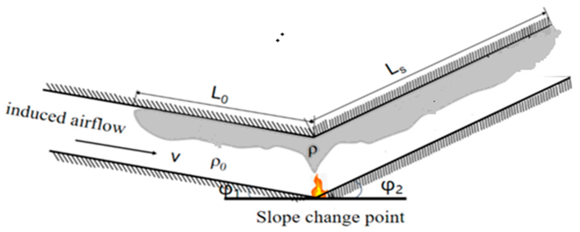
2. Theoretical Analysis

A schematic diagram of smoke flow when a fire occurs at the slope change point of an asymmetric V-shaped tunnel is shown in Figure 1. Due to the slope difference between the V-shaped two side tunnels, there will be thermal pressure difference between the two side tunnel, which induces longitudinal air-flow inside the tunnel, causing high-temperature smoke flowing towards the large slope tunnel side. The smoke flow is influenced by the slope on both sides of the V-shaped tunnel, the side tunnel length, the cross-sectional size, and the fire HRR. In order to systematically analyze the influences of the fire HRR and the small slope and large slope of V-shaped tunnel on the induced airflow and the maximum ceiling temperature rise, the dimensional analysis method was used to obtain the relationships between the induced airflow velocity and maximum ceiling temperature rise with those main influencing factors, which can be expressed as follows:
For a V-shaped tunnel with a length of Ls on both sides, due to the imbalance of stack effects on both sides of the slope change point, the induced airflow velocity v is calculates as follows:
f ( v , Q , ρ 0 , c p , g , T 0 , h , φ 1 , φ 2 , L s ) = 0
The maximum ceiling temperature rise is calculated as follows:
  f T m a x , Q , ρ 0 , c p , T 0 , g , h , φ 1 , φ 2 , L s = 0
According to the π theorem, M (kg), L (m), t (s), and T (°C) are selected as the four basic dimensions. Through a dimensional analysis, the expression for the dimensionless induced airflow velocity v* can be obtained as follows:
v * = v g h = f Q ρ 0 g 3 / 2 h 7 / 2 , φ 1 , φ 2 , L s h , c p T 0 g h = f Q c p ρ 0 g 1 / 2 h 5 / 2 , φ 1 , φ 2 , L s h
The effects of the tunnel slope and length are unified into the dimensionless height difference H* at the portals on both sides of the tunnel. For asymmetric V-shaped tunnels, the dimensionless height difference H* at the portals on both side tunnel is as follows:
H * = H h = L s ( sin ( arctan φ 2 ) sin ( arctan φ 1 ) ) h
We obtain the following:
v * = v g h = f Q c p ρ 0 g 1 / 2 h 5 / 2 , L s ( sin ( arctan φ 2 ) sin ( arctan φ 1 ) ) h k 1 Q * k 2 H * k 3
where Q * = Q c p ρ 0 T 0 g h 5 / 2
The maximum ceiling temperature rise ΔTmax can be obtained as follows:
Δ T max T 0 = f Q c p T 0 ρ 0 g 1 / 2 h 5 / 2 , φ 1 , φ 2 , L s h
where Δ T max = T max T 0 .
In the above equations, v is the induced airflow velocity, m/s; Q is the fire heat release rate, kW; ρ0 and T0 are the density and temperature of the ambient air, respectively, kg/m3 and K; cp is the specific heat of the air, kJ/kg·K; Ls is the length of one side of the V-shaped tunnel, m; φ1 and φ2 are the slopes of the two sides of the tunnel, %; H is the height difference at the portals on both side tunnel, m; h is the tunnel height, m; g is the gravity acceleration, m/s2; Tmax is the maximum ceiling temperature of smoke, K; K1, is a coefficient; and k2 and k3 are exponents.

3. Experimental Study

Following the scale law, a small-scale V-shaped tunnel was built, smoke spread in the V-shaped tunnel was studied, and the main factors that can influence the smoke flow in the V-shaped tunnel were investigated.

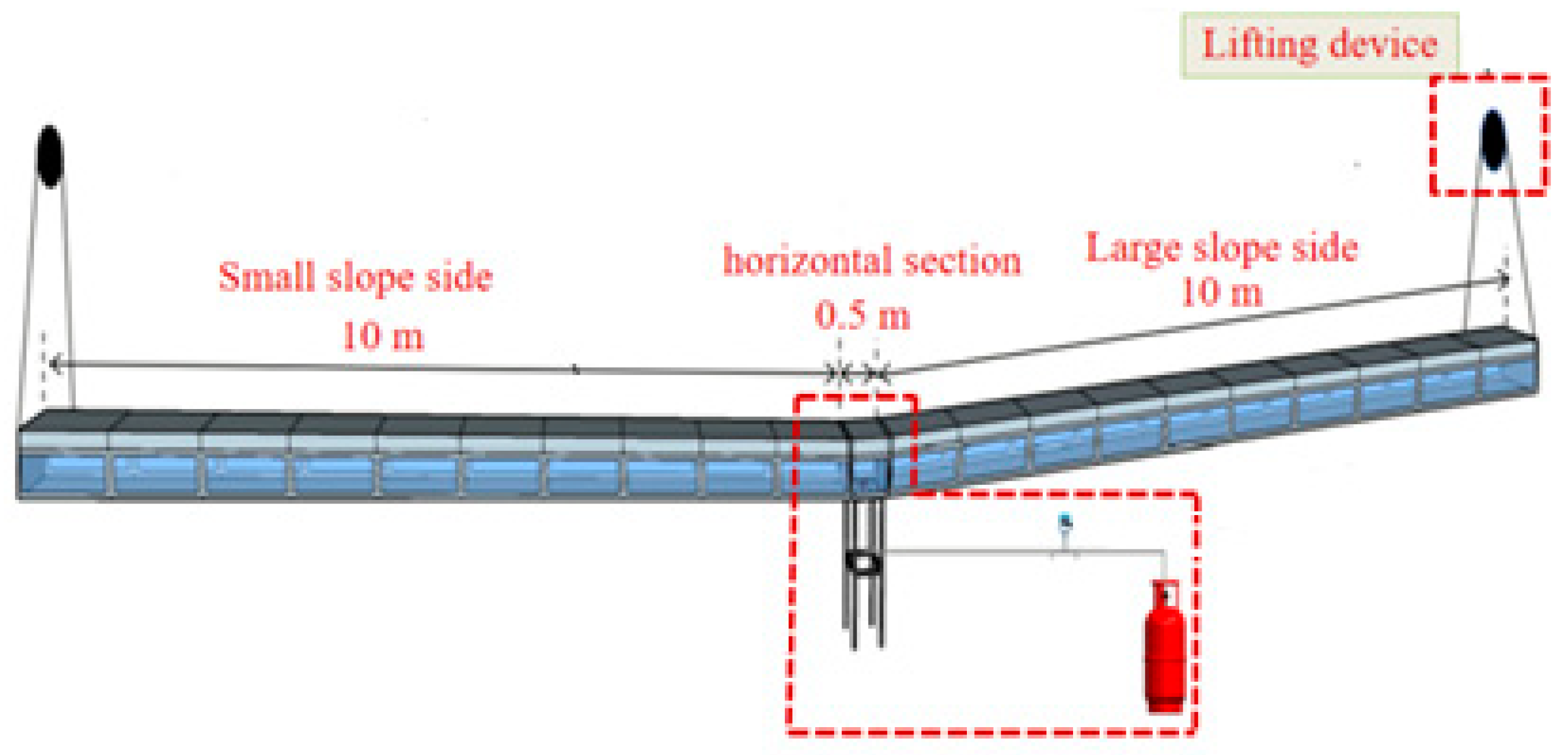
3.1. Experimental Scale-Model Tunnel

A 1:20 V-shaped scale-model tunnel was built based on one real tunnel in Beijing, as shown in Figure 2. The model tunnel was 20.5 m long, and it mainly consisted of three parts: variable slope sections on both sides and a horizontal section in the middle. The length of the variable slope section was 10 m, and the middle horizontal section was 0.5 m long. The width and the height of the tunnel were 0.675 m and 0.375 m, respectively. In order to achieve an adjustable slope on both sides of the tunnel, the chain on the lifting device was connected to the end of the variable slope section of the tunnel on both sides. The height of the tunnel end could be adjusted by pulling the chain to achieve a slope adjustment of 0–10°. For the convenience of observing experimental phenomena, transparent, fire-resistant glass was used on the front side.
The fire system consisted of six parts: a burner, gas tank, hose, pressure-reducing valve, rotameter, and copper tube. During the experiment, the gas flow could be adjusted by adjusting the opening size of the pressure-reducing valve and the rotameter valve so as to control the size of the fire HRR, and the fire HRR could be determined using Q = m · H c , where m · is the mass flow rate of the gas, and Hc is the calorific value of gas combustion.

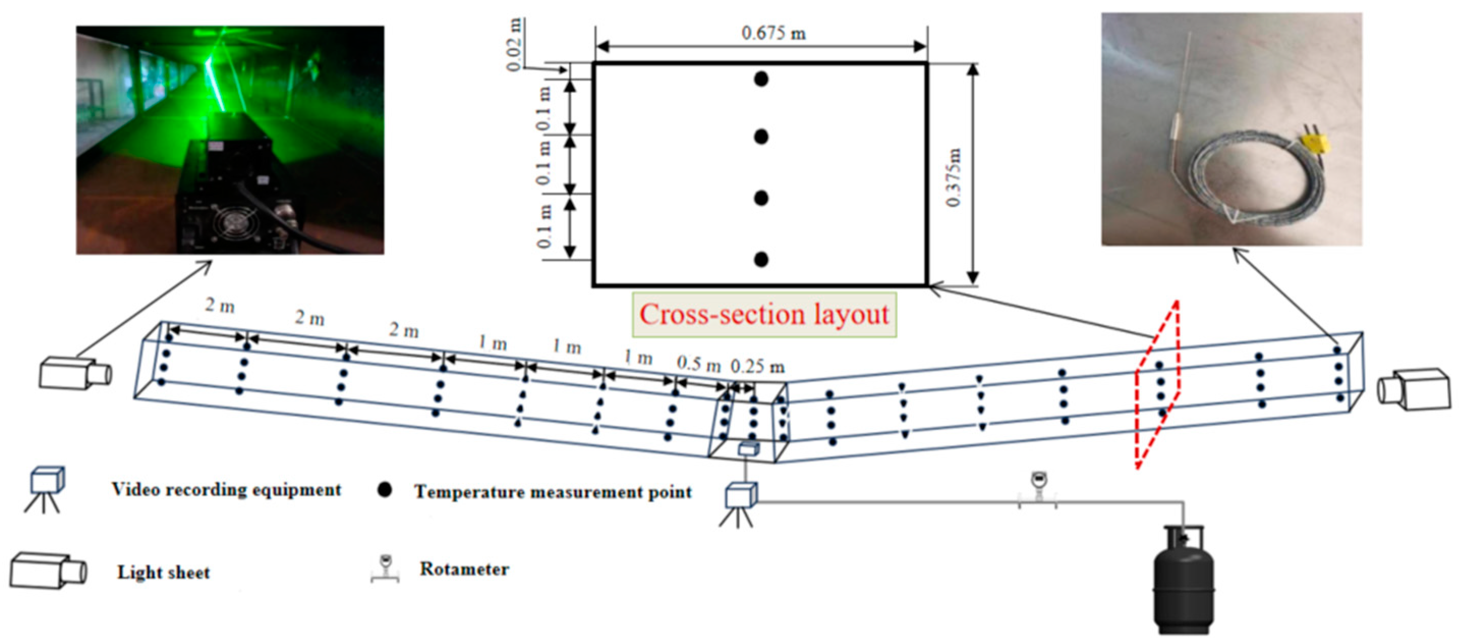
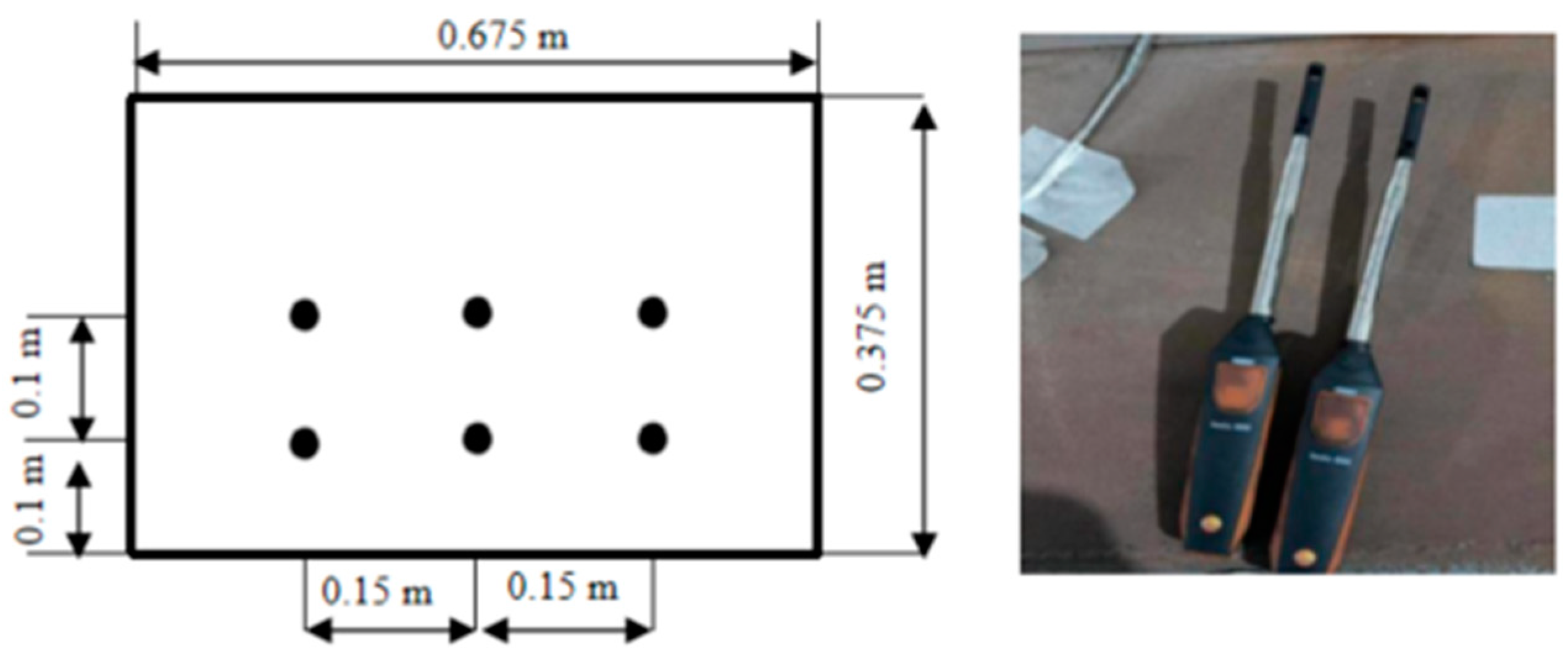
3.2. Measurement System

The temperature measurement and data acquisition system is mainly composed of K-type thermocouples, an Agilent 34970A data acquisition/data logger (Agilent Technologies, Santa Clara, CA, USA), and a computer. A total of 4 thermocouples are arranged along the height of the tunnel, and a total of 17 beams are arranged along the longitudinal direction of the tunnel, of which 3 beams are arranged in the horizontal section and 7 beams are arranged in the left and right sides of the tunnel. The spacing between the thermocouples is shown in Figure 3. The laser light source is placed at the entrance of both ends of the tunnel so that the smoke flow and the stratification and entrainment of the smoke can be clearly observed. A high-precision anemometer was used to measure the airflow velocity of the tunnel section through the side probe hole, and the flow velocity was the average of the velocity at the six measurement points, as shown in Figure 4.

3.3. Experimental Conditions

With reference to the Code for Design of Urban Underground Road Engineering (CJJ221-2015) [18], the slope of tunnels generally does not exceed 9%. In order to study the effects of different slope combinations on the smoke flow and maximum temperature rise, 1%, 3%, and 5% were selected as the slopes for the minor slope side of asymmetric V-shaped tunnels, and 3%, 5%, 7%, and 9% were selected as slopes for the major slope side. Generally, large vehicles and vehicles with dangerous goods are not allowed to pass through urban tunnels, and the fire design generally does not exceed 30 MW. Therefore, in order to study the influence of the fire HRR, fire HRRs of 5 MW, 10 MW, and 20 MW were selected for this study. In the model experiment, the fire HRRs were 2.80 kW, 5.59 kW and 11.18 kW, respectively. The experimental conditions are set as shown in Table 1.

4. Results and Discussion

Based on the experimental results, the effects of the fire HRR and slop compositions of the V-shaped tunnel on the fire-induced airflow velocity and the maximum ceiling temperature rise were analyzed.

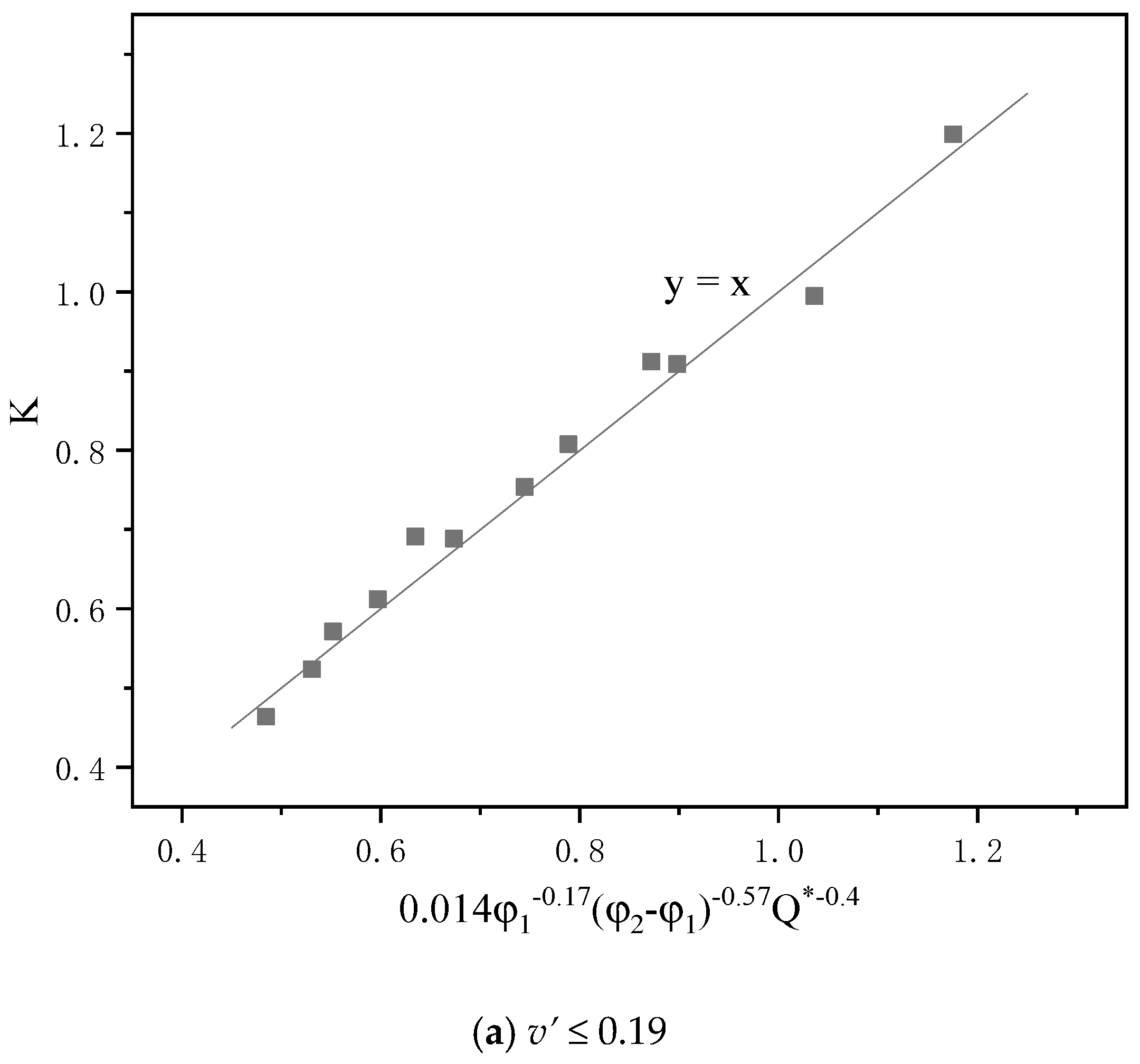
4.1. The Fire-Induced Airflow Velocity

Variations in the induced air flow in tunnel under different fire HRRs and different slope composition conditions are shown in Figure 5. It can be seen from the figure that the induced airflow velocity increases with increases in the fire HRR and the slope difference between the two sides of the tunnel. When the slope difference is the same, the larger the slope of the large slope side of the tunnel, the greater the induced airflow velocity. This is because of the increases in the slope difference and fire HRR, and the thermal pressure difference formed by hot smoke on the large slope side is greater than that on the small slope side tunnel so that the airflow velocity induced by this thermal pressure difference gradually increases.
It can be seen that the dimensionless induced airflow velocity v* varies with the dimensionless fire HRR Q* according to a power function, as shown in Equation (5). Firstly, the relationship between v* and Q* was studied, and the influence of H* on V* was considered in the coefficient. Thus, it is assumed that
v * = A Q * B
By fitting v* to Q*, it is found that when B is 0.288, the fitting R2 is above 90%, as shown in Figure 6. Table 2 presents the values of the fitting coefficients A and B.
By substituting Equation (7) into Equation (5), we obtain
v * / Q * 0.288 = k 1 H * k 3
where
v * = v g h ,   Q * = Q c p ρ 0 T 0 g h 5 / 2
From Table 2, it can be found that A is not only related to H* but also to φ1. Through fitting, the following can be obtained:
A = 1.82 φ 1 0.525 H * 0.634 φ 1 0.223
A dimensionless induced airflow velocity prediction model considering factors such as the tunnel slope, the fire HRR, as shown in Figure 7, and the height difference at the portals on both sides of the tunnel can be obtained as follows:
v * = 1.82 φ 1 0.525 H * 0.634 φ 1 0.223 Q * 0.288
By comparing the dimensionless induced airflow velocity calculated by Equation (10) with those experimental results, it was found that the error was within ±15%, as shown in Figure 8.

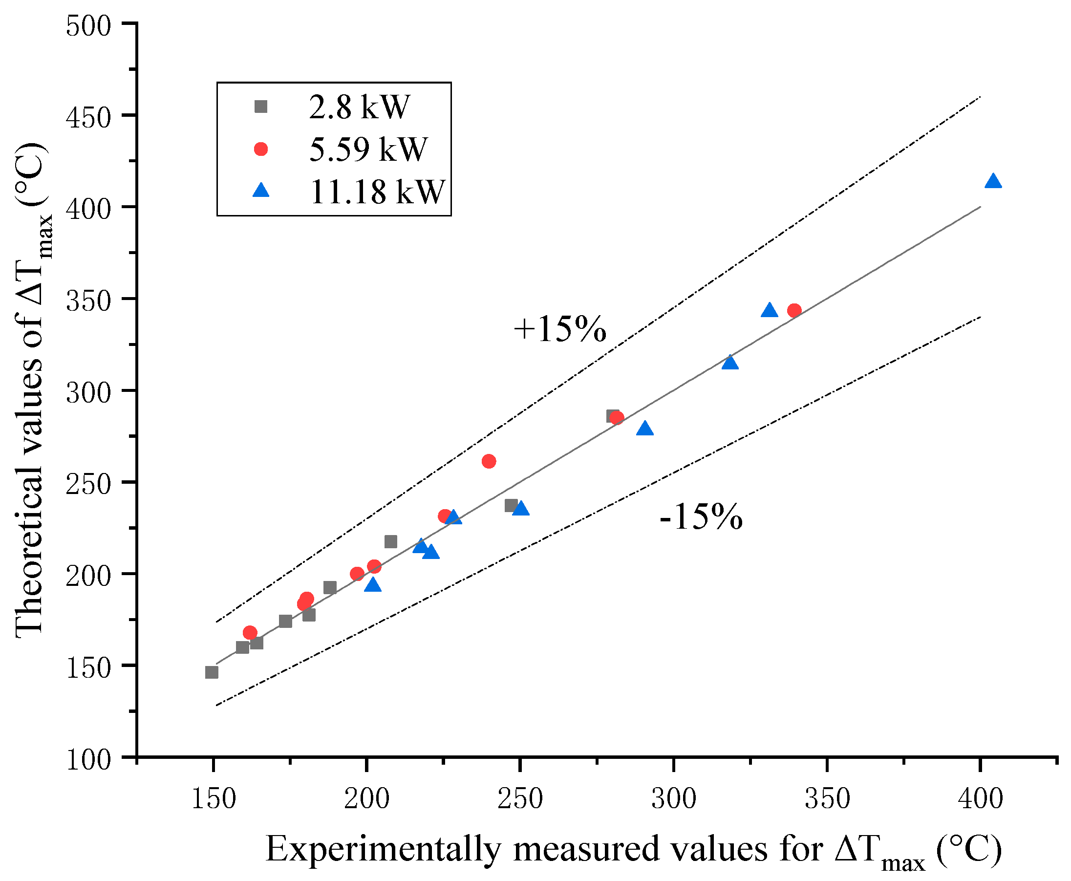
4.2. Maximum Ceiling Temperature Rise

Figure 9 shows the maximum temperature rise of V-shaped tunnel fires for different fire HRRs and slope compositions. It can be seen that the maximum temperature rise increases with the increase in the fire HRR. At the same fire HRR, as the slope difference between the two sides of the tunnel increases, the maximum temperature rise decreases. This is because as the slope difference increases, the induced airflow velocity in tunnel increases, and the flame will be blown toward the large slope of the tunnel and more heat will be taken away.
According to the analysis in the former parts, the maximum temperature rise in the V-shaped tunnel is related to the dimensionless HRR Q* and the slope and the length of the two sides of the tunnel. As for the maximum ceiling temperature in a tunnel fire under longitudinal ventilation, Li et al. [7,8,9] proposed the maximum ceiling temperature rise model for different longitudinal ventilation velocities, fire HRRs and tunnel geometries based on a theoretical analysis of a symmetrical fire plume and small-scale experiment as follows:
Δ T m a x = Q v b f 1 / 3 h s 5 / 3 v > 0.19 17.5 Q 2 / 3 h s 5 / 3 v 0.19
where
v = v ( g Q b f ρ C p T 0 ) 1 / 3
In the above equation, bf is the radius of the fire source, m; hs is the height from the surface of the fire source to the tunnel ceiling, m; v’ is the dimensionless ventilation velocity; and v is the longitudinal ventilation velocity in the tunnel, m/s.
Based on the model of Li et al., this study introduces a correction factor K that takes into account the effects of the slope composition. The model for predicting the maximum temperature rise in V-shaped tunnels can be expressed as follows:
Δ T m a x = K Δ T m a x = K Q v b f 1 / 3 h s 5 / 3 v * > 0.19 17.5 K Q 2 / 3 h s 5 / 3 v * 0.19
Figure 10 shows the variation in K with Q* under different slope combinations, and it can be seen that K decays in a power function form with Q*. For v 0.19 , by fitting K to Q*, a power function relationship of K = A 1 Q * 0.14 can be obtained. For v > 0.19 , a power function relationship of K = A 2 Q * 0.51 can be obtained. The fitting correlation coefficients are all above 90%. It can also be seen from Figure 10 that K decreases with an increase in the slope difference between the two sides of the tunnel and the slope of the small slope side of the tunnel. The fit of K with the slope composition and dimensionless fire heat release rate Q* is shown in Figure 11, and the correction coefficient K can be finally obtained as
K = 0.014 φ 1 0.17 ( φ 2 φ 1 ) 0.57 Q * 0.4 v 0.19 15.4 φ 1 0.3 ( φ 2 φ 1 ) 1.16 Q * 0.51 v > 0.19
The maximum ceiling temperature rise in the V-shaped tunnel can be expressed as
Δ T max = 0.245 φ 1 0.17 ( φ 2 φ 1 ) 0.57 Q * 0.4 Q 2 / 3 h s 5 / 3 v 0.19 15.4 φ 1 0.3 ( φ 2 φ 1 ) 1.16 Q * 0.51 Q v b f 1 / 3 h s 5 / 3 v > 0.19
where
v = 1.82 g h φ 1 0.525 H * 0.634 φ 1 0.223 Q * 0.288
Comparing the calculated maximum ceiling temperature rise from Equation (14) with those experimental results, as shown in Figure 12, it was found that Equation (14) can give good results, and the prediction error is within ±15%.

5. Conclusions

The influences of the slope structure of the V-shaped tunnel and fire HRR on fire-induced airflow and the maximum ceiling temperature rise in the tunnel were studied by combining the theoretical analysis and small-scale model experiment in this paper, and the main conclusions are as follows:
(1)
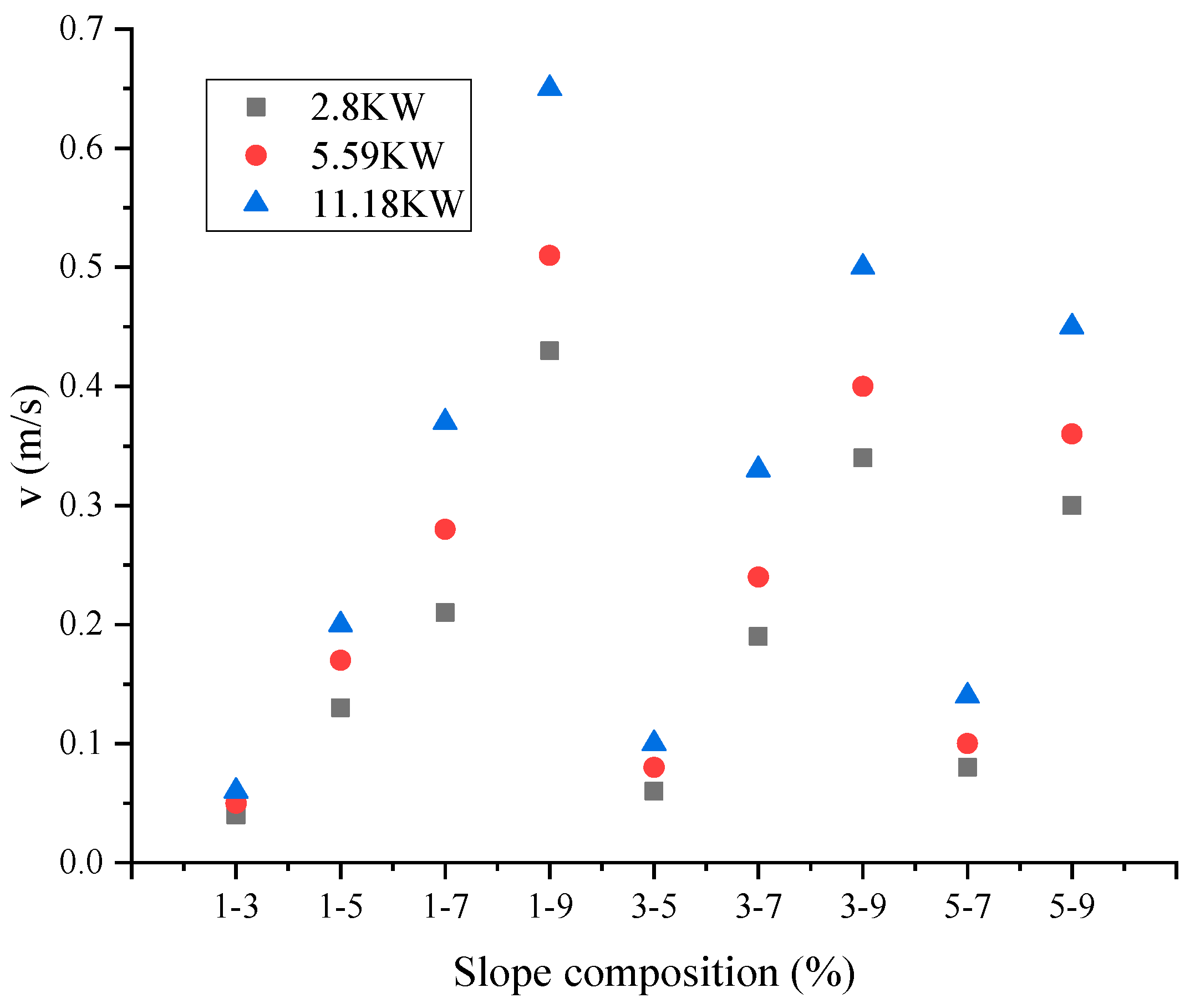
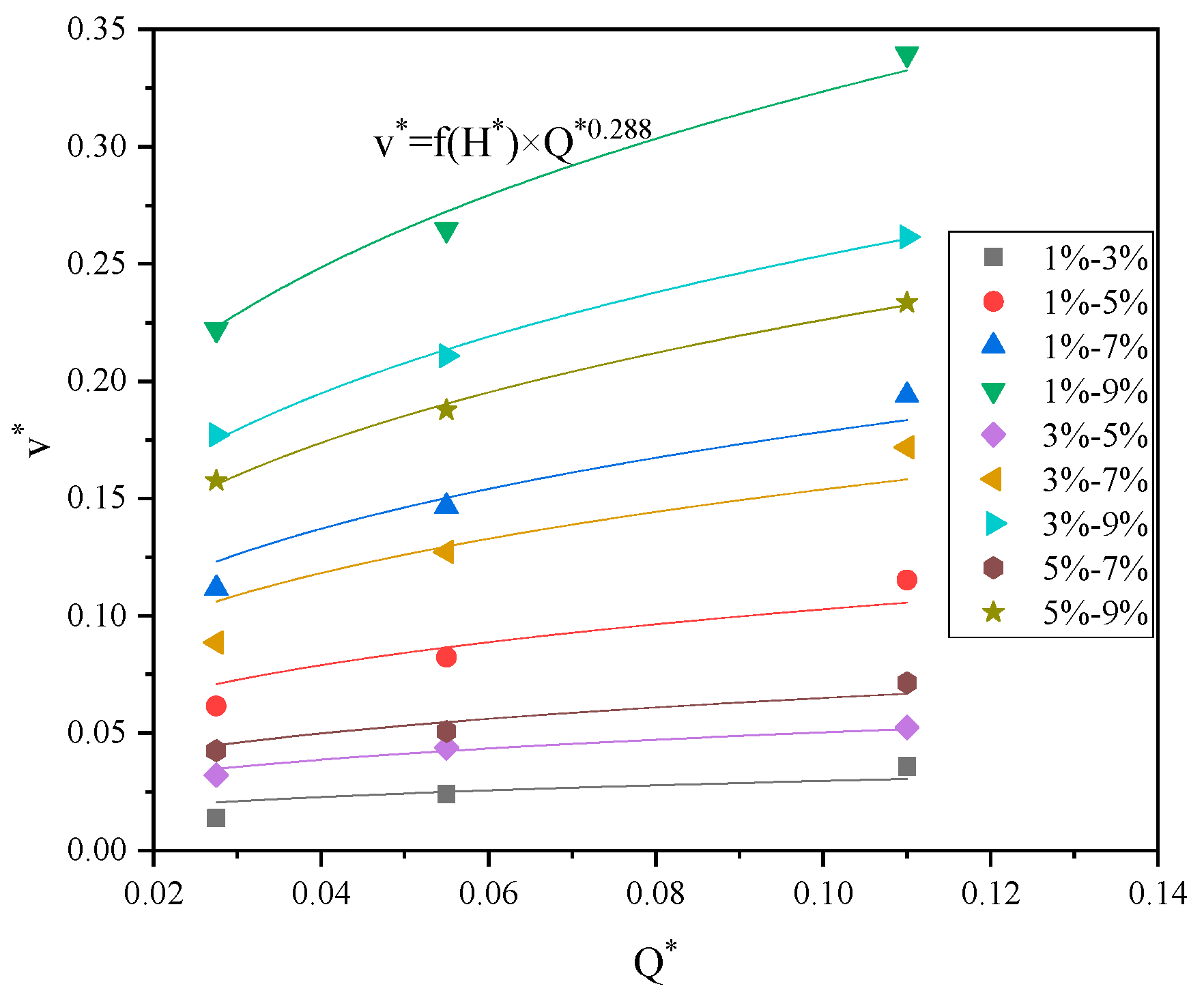
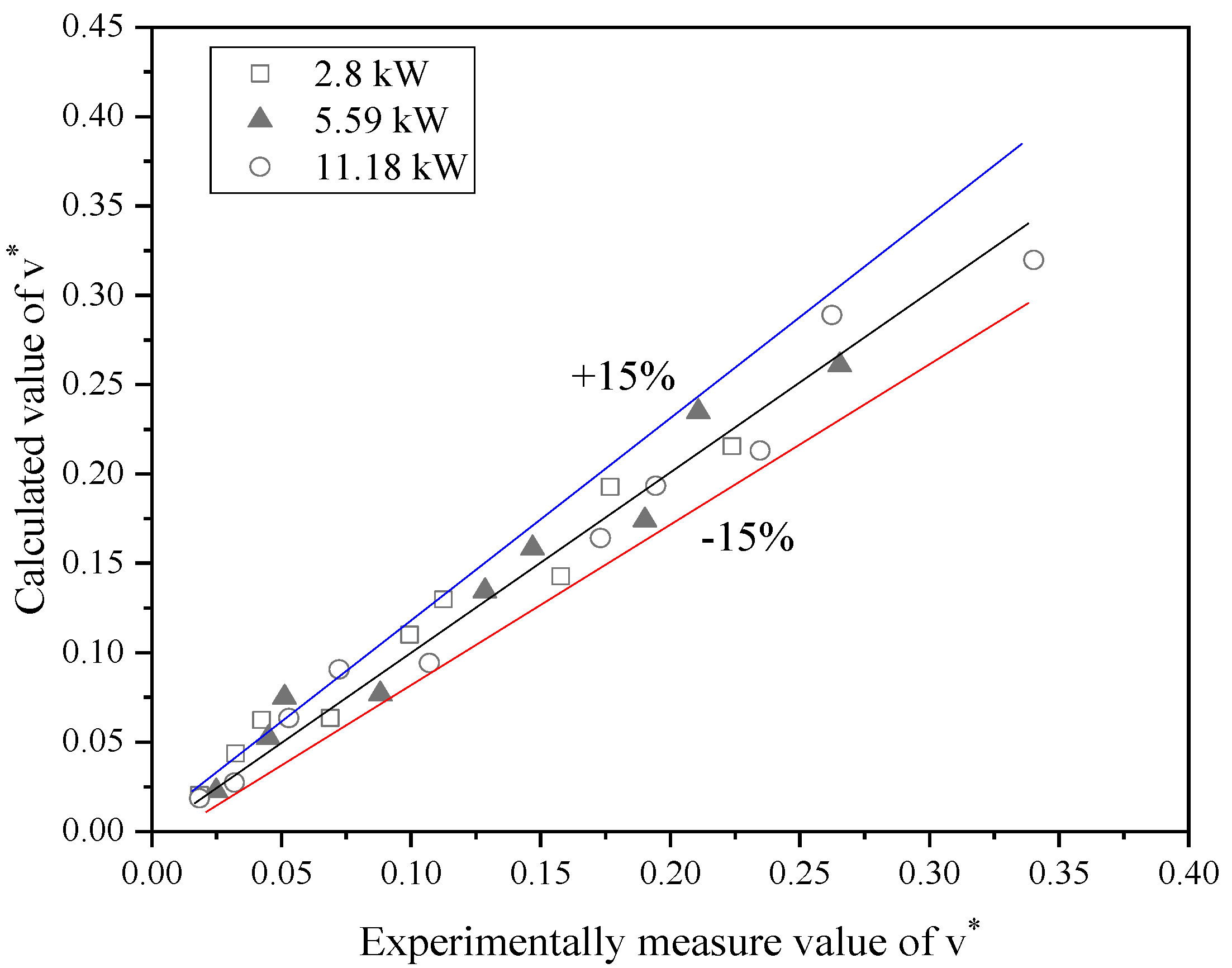
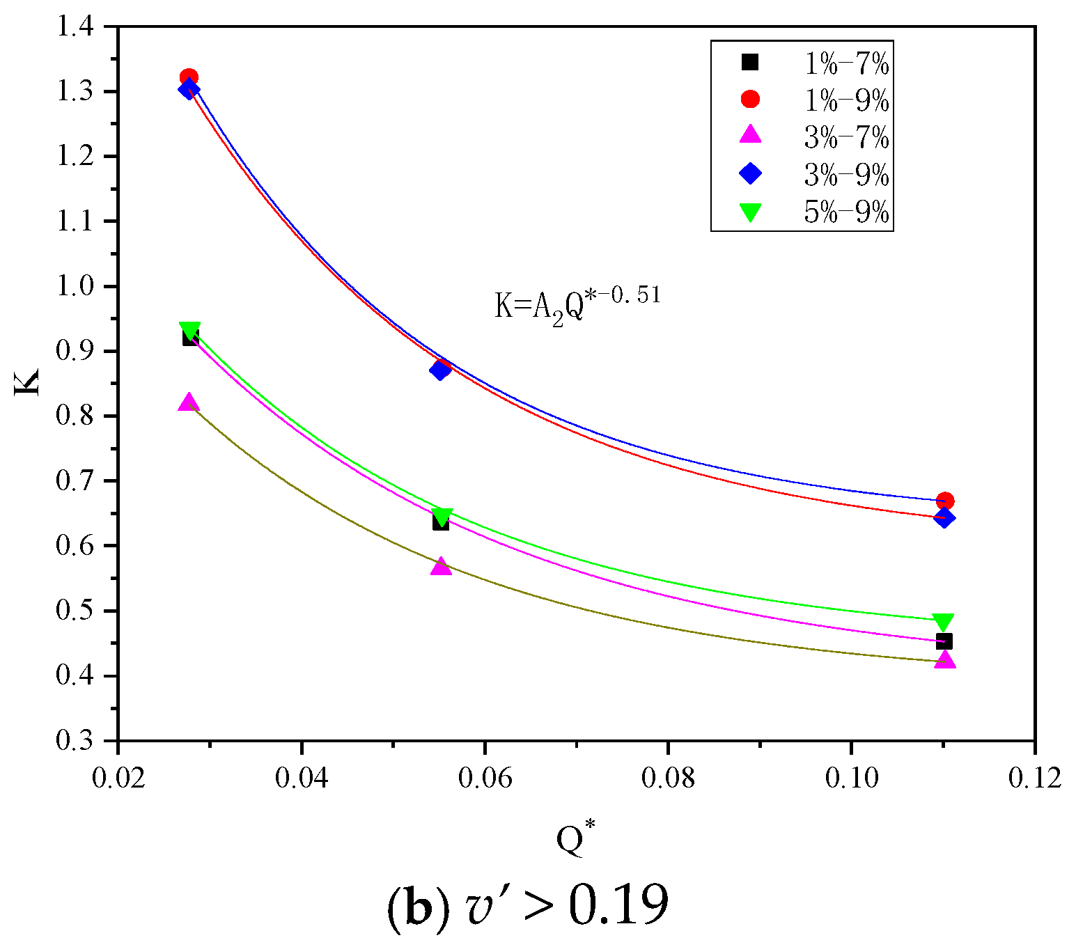
Due to the thermal pressure differences between the large slope side and small slope side of the V-shaped tunnel, it is found that the fire-induced airflow flow steadily increases from the small slope side to the large slope side. The dimensionless induced airflow velocity v* is mainly related to the dimensionless fire heat release rate Q* and the dimensionless height difference H*. When the slope difference is the same, it increases with the slope of the small slope side of the tunnel. A dimensionless inlet induced airflow velocity prediction model is proposed.
(2)
Due to the fire-induced airflow, the fire flame is blown directly to the large slope side, the temperature decreases with the increase in the slope difference between the two sides of the tunnel, and increases with the increase in the fire HRR, and an empirical model for the maximum ceiling temperature rise is obtained.
The above conclusions are based on the working conditions listed in this study, but there are still some limitations in this research. This study only investigated the situation where the fire source is located at the slope change point, and in reality, the location of tunnel fires is relatively random. In addition, this study only investigated the situation of side tunnels with the same lengths, and the effects of the tunnel length, especially the side tunnels with different lengths, on smoke flow in the tunnel should be further studied in the future.

Author Contributions

Conceptualization, J.L. and Y.L.; methodology, Q.D. and J.L.; formal analysis, Q.D., H.L. and H.Z.; writing—original draft preparation, Q.D. and H.L.; writing—review and editing, J.L.; funding acquisition, J.L. All authors have read and agreed to the published version of the manuscript.

Funding

This research was funded by the Beijing Natural Science Foundation (Grant No. 8222002).

Institutional Review Board Statement

Not applicable.

Informed Consent Statement

Not applicable.

Data Availability Statement

The data presented in this study are available upon request from the corresponding author.

Conflicts of Interest

Author Qiwei Dong was employed by the company Beijing General Municipal Engineering Design & Research Institute, and he is also a part time PhD student in Beijing University of Technology. The remaining authors declare that the research was conducted in the absence of any commercial or financial relationships that could be construed as a potential conflict of interest.

References

  1. Yin, Y.; Xu, Z.; Zhao, J.; Mahmood, S.; Xie, B.; Liu, Q. The effect of width and slope in uniclinal V-shaped underground space on air transport and smoke characteristics under thermal stack effect. Therm. Sci. Eng. Prog. 2024, 51, 102599. [Google Scholar] [CrossRef]
  2. Li, J.; Li, Y.F.; Cheng, C.H.; Chow, W.K. A study on the effects of the slope on the critical velocity for longitudinal ventilation in tilted tunnels. Tunn. Undergr. Space Technol. 2019, 89, 262–267. [Google Scholar] [CrossRef]
  3. Li, J.; Liu, W.; Li, Y.; Chow, W.K.; Chow, C.L.; Cheng, C.K. Scale modelling experiments on the effect of longitudinal ventilation on fire spread and fire properties in tunnel. Tunn. Undergr. Space Technol. 2022, 130, 104725. [Google Scholar] [CrossRef]
  4. Tu, D.; Li, J.; Li, Y.; Xu, D. Numerical study on the influence of the slope composition of the asymmetric V-Shaped tunnel on smoke spread in tunnel fire. Fire 2024, 7, 363. [Google Scholar] [CrossRef]
  5. Kurioka, H.; Oka, Y.; Satoh, H.; Sugawa, O. Fire properties in near field of square fire source with longitudinal ventilation in tunnels. Fire Saf. J. 2003, 38, 1468–1483. [Google Scholar] [CrossRef]
  6. Hu, L.H.; Huo, R.; Peng, W.; Chow, W.K.; Yang, R.X. On the maximum smoke temperature under the ceiling in tunnel fires. Tunn. Undergr. Space Technol. 2006, 21, 650–655. [Google Scholar] [CrossRef]
  7. Li, Y.Z.; Lei, B.; Ingason, H. The maximum temperature of buoyancy-driven smoke flow beneath the ceiling in tunnel fires. Fire Saf. J. 2011, 46, 204–210. [Google Scholar] [CrossRef]
  8. Ingason, H.; Li, Y.Z. Model scale tunnel fire tests with longitudinal ventilation. Fire Saf. J. 2010, 45, 371–384. [Google Scholar] [CrossRef]
  9. Li, Y.Z.; Ingason, H. The maximum ceiling gas temperature in a large tunnel fire. Fire Saf. J. 2012, 48, 38–48. [Google Scholar] [CrossRef]
  10. Hu, L.H.; Chen, L.F.; Wu, L.; Li, Y.F.; Zhang, J.Y.; Meng, N. An experimental investigation and correlation on buoyant gas temperature below ceiling in a slopping tunnel fire. Appl. Therm. Eng. 2013, 51, 246–254. [Google Scholar] [CrossRef]
  11. Oka, Y.; Sugawa, O.; Imamura, T. Correlation of temperature rise and velocity along an inclined fire plume axis in crosswinds. Fire Saf. J. 2008, 43, 391–400. [Google Scholar] [CrossRef]
  12. Oka, Y.; Kakae, N.; Imazeki, O.; Inagak, K. Temperature property of ceiling jet in an inclined tunnel. Procedia Eng. 2013, 62, 234–241. [Google Scholar] [CrossRef]
  13. Ji, J.; Wan, H.X.; Li, K.Y.; Han, J.; Sun, J. A numerical study on upstream maximum temperature in inclined urban road tunnel fires. Int. J. Heat Mass Transf. 2015, 88, 516–526. [Google Scholar] [CrossRef]
  14. Ji, J.; Wang, Z.Y.; Ding, L.; Yu, L.; Gao, Z.; Wan, H. Effects of ambient pressure on smoke movement and temperature distribution in inclined tunnel fires. Int. J. Therm. Sci. 2019, 145, 106006. [Google Scholar] [CrossRef]
  15. Zhong, M.H.; Shi, C.L.; He, L.; Shi, J.H.; Liu, C.; Tian, X.L. Smoke development in full-scale sloped long and large curved tunnel fires under natural ventilation. Appl. Therm. Eng. 2016, 108, 857–865. [Google Scholar] [CrossRef]
  16. Xie, E.; Zhao, W.; Xu, Z.; Zhang, X.; Wu, W.; Wang, T.; He, L. A numerical study on smoke back-layering length in V-shaped tunnels under natural ventilation. Fire Mater. 2022, 46, 1208–1221. [Google Scholar] [CrossRef]
  17. Jiang, X.P.; Chen, X.G.; Xiao, N.Q.; Liao, X.; Fan, C. Influence of the competitive effect of V-shaped slope tunnel on smoke characteristics. Tunn. Undergr. Space Technol. 2021, 118, 104193. [Google Scholar] [CrossRef]
  18. CJJ221-2015; Code for Design of Urban Underground Road Engineering. China Architecture Publishing & Media Co., Ltd.: Beijing, China, 2015. (In Chinese)
Figure 1. Diagrammatic sketch of the smoke flow in a V-shaped tunnel.
Fire 07 00483 g001
Figure 2. Schematic diagram of the V-shaped model tunnel.
Fire 07 00483 g002
Figure 3. Schematic diagram of the temperature measurement points.
Fire 07 00483 g003
Figure 4. Anemometer and velocity measurement point distribution.
Fire 07 00483 g004
Figure 5. Variations in the induced airflow velocity with the slope compositions of the V-shaped tunnel and HRR.
Fire 07 00483 g005
Figure 6. Variation of v* with Q*.
Fire 07 00483 g006
Figure 7. Variation of v*/Q* with H*.
Fire 07 00483 g007
Figure 8. Comparison of v* calculated by Equation (10) with the experimentally measured v*.
Fire 07 00483 g008
Figure 9. Variation in the maximum ceiling temperature rise for different slope compositions and different HRRs.
Fire 07 00483 g009
Figure 10. Variations in the correction coefficient K with Q* for different v’ values.
Fire 07 00483 g010aFire 07 00483 g010b
Figure 11. Variations in K with the slope difference and dimensionless fire heat release rate.
Fire 07 00483 g011aFire 07 00483 g011b
Figure 12. Comparison of ΔTmax calculated with Equation (14) with the experimentally measured ΔTmax.
Fire 07 00483 g012
Table 1. Experimental conditions.
Experimental ConditionFire HRRSlope CompositionExperimental ConditionFire HRRSlope Composition
A12.8 kW1–3%C111.18 kW1–3%
A21–5%C21–5%
A31–7%C31–7%
A41–9%C41–9%
A53–5%C53–5%
A63–7%C63–7%
A73–9%C73–9%
A85–7%C85–7%
A95–9%C95–9%
B15.59 kW1–3%
B21–5%
B31–7%
B41–9%
B53–5%
B63–7%
B73–9%
B85–7%
B95–9%
Table 2. The values of the fitting coefficients A and B.
Slope of the Large Slope Side of the TunnelSlope of the Small Slope Side of the Tunnel
1%3%5%
ABABAB
3%0.057450.288————————
5%0.199460.2880.097660.288————
7%0.346480.2880.298690.2880.1260.288
9%0.627980.2880.492360.2880.4390.288
Disclaimer/Publisher’s Note: The statements, opinions and data contained in all publications are solely those of the individual author(s) and contributor(s) and not of MDPI and/or the editor(s). MDPI and/or the editor(s) disclaim responsibility for any injury to people or property resulting from any ideas, methods, instructions or products referred to in the content.

