Article

A Comparative Numerical Study of Lithium-Ion Batteries with Air-Cooling Systems towards Thermal Safety

1
Department of Fire Safety Engineering, Southwest Jiaotong University, Chengdu 611731, China
2
School of Civil Engineering, University of Queensland, Brisbane, QLD 4072, Australia
3
Department of Architecture and Civil Engineering, City University of Hong Kong, Hong Kong SAR, China
4
School of Mechanical and Manufacturing Engineering, University of New South Wales, Sydney, NSW 2052, Australia
*
Authors to whom correspondence should be addressed.
Submission received: 15 December 2023 / Revised: 10 January 2024 / Accepted: 10 January 2024 / Published: 15 January 2024

Abstract

:
Given the growing demand for increased energy capacity and power density in battery systems, ensuring thermal safety in lithium-ion batteries has become a significant challenge for the coming decade. Effective thermal management plays a crucial role in battery design optimization. Air-cooling temperatures in vehicles often vary from ambient due to internal ventilation, with external air potentially overheating due to vehicle malfunctions. This article highlights the efficiency of lateral side air cooling in battery packs, suggesting a need for further exploration beyond traditional front side methods. In this study, we examine the impact of three different temperature levels and two distinct air-cooling directions on the performance of an air-cooling system. Our results reveal that the air-cooling direction has a more pronounced influence compared with the air-cooling temperature. By employing an optimal air-cooling direction and ambient air-cooling temperature, it is possible to achieve a temperature reduction of approximately 5 K in the battery, which otherwise requires a 10 K decrease in the air-cooling temperature to achieve a similar effect. Therefore, we propose an empirical formula for air-cooling efficiency under various conditions, aiming to provide valuable insights into the factors affecting air-cooling systems for industrial applications toward enhancing the fire safety of battery energy storage systems.

1. Introduction

With the continuous improvement of energy density and power density in lithium-ion batteries, safety concerns regarding large-scale battery packs have become prominent [1,2,3,4]. As the automotive market drives the expansion of lithium-ion production, these batteries may also enter stationary service as well, facilitating the implementation of renewable energy technologies such as solar and wind. Incidents of fire accidents caused by thermal runaway in lithium-ion batteries occur frequently [5,6,7,8,9]. When heat dissipation is not achieved in a timely fashion, the battery temperature will inevitably rise, affecting its performance, shortening its service life, and potentially leading to thermal runaway and severe safety issues. A lot of research has been conducted, forcing on developing new batteries [10,11] and improving battery safety [12,13], but the cooling system is still needed for the overall battery system. Generally, thermal runaway occurs when the heat losses to the environment do not offset the heat generated by exothermic reactions. This accumulated heat drives the temperature increase, which, in turn, produces an exponential growth in the reaction rates. In the case of lithium-ion batteries, an undesirable temperature increase can occur within the battery due to electrical or mechanical abuse or an external heating source. If the heat generation rate exceeds the heat dissipation rate in the environment, the temperature will continue to rise. When reaching some critical temperatures, especially the collapse temperature of the separator, the cell will break down [14,15,16,17,18]. Therefore, efficient thermal management systems play a significant role in ensuring that batteries operate within the appropriate temperature range [19,20]. The role of the battery thermal management system (BTMS) is to regulate the temperature of the battery within suitable ranges during all operating conditions, including cooling and heating insulation, to maintain its optimal performance and state of charge. Depending on the cooling medium, the thermal management of the battery system can be classified into several forms, including air-cooling systems [21,22,23,24], liquid-cooling systems [25,26,27,28], phase-change material systems [29,30,31,32,33], heat-pipe cooling systems [34,35,36,37,38], and hybrid cooling systems [39,40,41,42,43].
The choice of a battery cooling system depends on factors such as the type of battery, operational conditions, size and weight constraints, and cost considerations. Many electric vehicles and energy storage systems use a combination of these cooling methods to optimize performance and reliability. For evaluating the performance of cooling systems, temperature is the key parameter of the performance of the battery cooling methods, which is also linked to many other performances, such as charge acceptance, energy capability, reliability, etc. Handling the charge/discharge cycle and governing the battery heat growth are two key topics of concern in battery thermal management. Regarding temperature, maximum temperature and temperature difference are two critical factors for battery thermal management.
Compared with liquids, air has lower specific heat capacity as well as worse thermal conductivity. Air-cooling systems are one of the most widely used BTMSs in EVs due to their low cost, simple design, low weight, easy maintenance, and no leakage issues compared with other cooling systems. There are three types: direct ambient air cooling, passenger cabin air conditioning air cooling, and dedicated evaporator air cooling [44,45]. Direct ambient air cooling relies on the surrounding air, while passenger cabin air conditioning uses the vehicle’s system. Dedicated evaporator air cooling is a separate system for precise temperature control [46,47]. Research focuses on optimizing battery arrangement, airflow distribution, and control strategies for the BTMS. Zhang et al. [48] discovered that implementing a reciprocating flow in the system led to a 60% reduction in temperature difference compared with a system with unidirectional flow. Mahamud et al. [49] conducted a numerical investigation on the impact of the reciprocating flow period in an air-cooled system. They found that a cycle of 120 s resulted in a maximum temperature reduction of 1.5 K and a temperature difference decrease of 72% within the battery pack. Liu et al. [50] utilized the orthogonal test method to examine the effects of inlet temperature, inlet airflow rate, and reciprocating period on a serial cooling system’s performance. Through optimization, they achieved a temperature difference reduction of 3.76 K. Zhuang et al. [51] focused on improving the performance of a serial cooling system by designing the lateral and longitudinal spacings of battery cells and adding prismatic spoilers. They then introduced periodic reciprocating flow to regulate the flow type, resulting in a significant 76.4% reduction in the system’s power consumption. He et al. [52] regulated the airflow type of a serial cooling system based on the position of the highest temperature. Their research demonstrated that the system with this control strategy achieved an 84% reduction in power consumption compared with a system without the control strategy. Wang et al. [53] conducted experimental investigations on the cooling performance of a single battery using reciprocating airflow. They designed a control strategy based on the battery temperature difference to adjust the airflow type, ensuring that the temperature difference remained within 4.9 °C. Additionally, Liu et al. [54] proposed a control strategy for an air-cooled system that involved switching flow types among J-type flow, U-type flow, and Z-type flow. This strategy effectively maintained the temperature difference within 1.33 K. Furthermore, the internal battery thermal propagation behaviors have also been recently studied by molecular dynamics (MD) approaches, which involve the reactive forcefields (ReaxFF) approach to comprehensively study the detailed thermal degradation mechanisms [55,56,57]. These data can thereby be coupled with thermal abuse models or pyrolysis models in computational fluid dynamics (CFD) for further analysis of thermal runaway analysis of specific battery components based on their corresponding material compositions [58,59].
Most research studies in the field primarily concentrate on the air-cooling configuration when investigating battery cooling. However, it is worth noting that the fundamental airflow scenarios can significantly impact the cooling effectiveness.
  • In practical terms, within real-world air-cooling systems, it is frequently observed that the air-cooling temperatures do not precisely match the ambient temperatures. This discrepancy is particularly notable post-transition through the vehicle’s internal ventilation mechanisms. Crucially, it is imperative to acknowledge that air entering the cooling system from external sources may be subject to overheating, especially under circumstances of malfunction in disparate components of the vehicle. This phenomenon necessitates a comprehensive evaluation of the design and operational strategies of air-cooling systems.
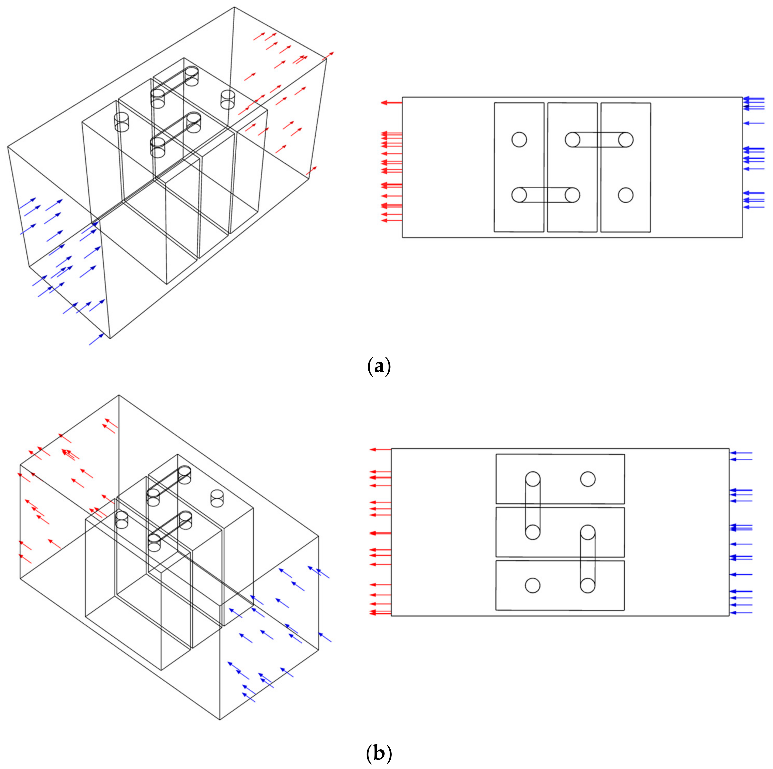
  • The maximum temperature of the battery pack is always found in the middle cells of the pack; however, in traditional air-cooling directions, the middle cells of the battery pack do not receive optimal cooling. Therefore, this paper aims to enhance the efficiency of the air-cooling system by altering the direction of air cooling.
Hence, this study aims to enhance the understanding of thermal behavior in batteries by employing a comprehensive electrothermal battery model. Specifically, the analysis focuses on examining the thermal performance under varying air-cooling temperatures and air-cooling directions through CFD techniques. The outcomes of this study are expected to provide valuable insights for optimizing battery cooling strategies in practical applications.

2. Numerical Methods and Modelling
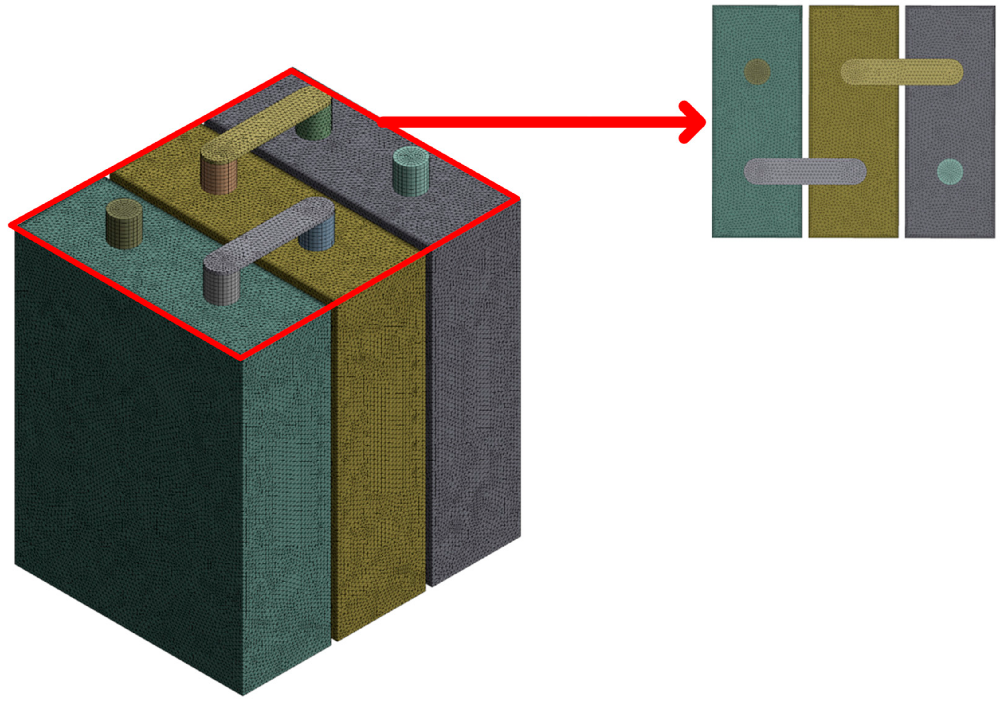
2.1. CFD Model

Compared with the experimental analysis, numerical simulations utilizing the CFD approach have found extensive application across diverse research and industrial domains [60,61,62,63,64]. CFD is mainly dedicated to fluids in motion and how fluid flow behavior influences processes, including heat transfer and possibly chemical reactions in combusting flows. Mathematical equations are applied to describe the fluid motion by physical characterization, usually in partial differential form, called governing equations. These applications encompass performance assessment, behavioral predictions, and the substitution of impractical tests, such as those involving fire dynamics [65,66,67,68], chemical mechanisms and transportation of soot particles [69,70,71,72,73], contribution toward numerical database for fire safety standards [74,75,76,77,78,79], etc. Therefore, understanding the fundamental thermal degradation kinetics will contribute to thermal runaway analysis in the battery-CFD modelling framework.
In essence, CFD modelling is fundamentally based on the governing equations of fluid dynamics. These equations represent the mathematical statement of the conservation laws of physics. Also, the CFD model stands for the basic description of the fluid flow processes [80,81]. The appropriate numerical form of the physical boundary condition depends on the mathematical form of the governing equations and numerical algorithm used [82,83,84,85]. Generally, the governing equations include mass, momentum, and energy conservation, which are expressed below:
The mass conservation equation:
ρ a t + ϑ = 0
The momentum conservation equation:
( ρ a ϑ ) t + ( ρ a ϑ ϑ ) = P a
The energy conservation equation:
( ρ a C p a T a ) t + · ( ( ρ a C p a ) ϑ T a ) = · ( K a T a )
These governing equations are used for computational procedures in finite difference or finite volume methods. In these equations, ρ, Cpa, T, P, and K stand for the density, specific heat, temperature, pressure, and heat conductivity coefficient, respectively. The subscript a denotes the cooling air.
For the battery cell, the governing equations also can be applied. More specifically, the energy equation can be written as follows:
ρ b C p b T t = · ( K b T ) + q
where q represents the heat generation rate per unit volume of a single battery, and the subscript b denotes the battery cell.
Moreover, the CFD methodology provides a numerical solution for turbulence flow [86,87,88,89]. The shear-stress transport k-ω model simulates the turbulence flow during the battery pack cooling process. The k-ω model has improved the accuracy of the turbulence model for predicting free shear flows. The major two components, turbulence kinetic energy k and the specific dissipation rate ω, are calculated from the below transport equations:
t ( ρ k ) + x i ( ρ k u i ) = x j Γ k k x j + G k Y k + S k + G b
t ( ρ ω ) + x i ( ρ ω u i ) = x j ( Γ ω ω x j ) + G ω Y ω + D ω + S ω + G ω b
where Gk represents the production of turbulence kinetic energy; Gω represents the generation of specific dissipation rate ω. Γ; Y and S represent the effective diffusivity, the dissipation, and user-defined source terms, respectively. Dω stands for the cross-diffusion term. Moreover, Gb and Gωb account for buoyancy terms. All the terms are calculated by the CFD software ANSYS FLUENT 2023 R2 during the simulation process.

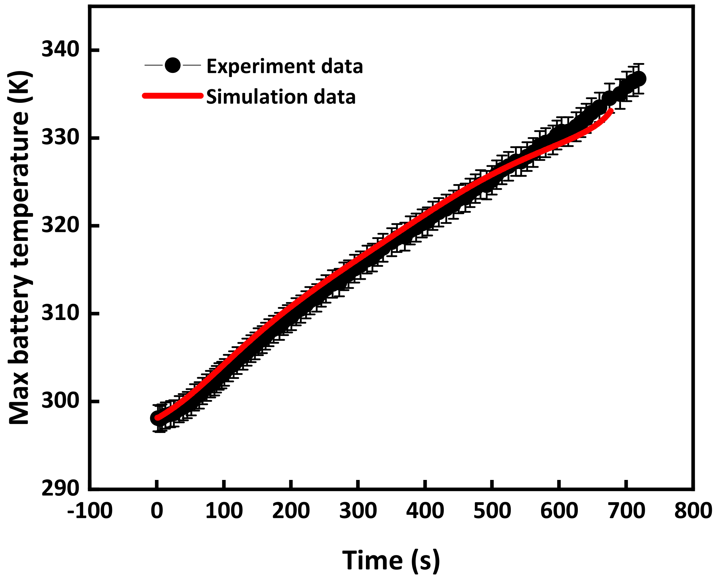
2.2. The Battery Cell Model and Validation

A typical battery cell unit comprises four main components, including an anode, a cathode, a separator, and an electrolyte. The proposed battery model mainly focuses on conducting a thermal analysis of a battery cell or battery pack during normal operation conditions. The coupled thermal-electrochemical model is applied to simulate the produced heat and compute the heat generation rate.
Figure 1 describes two different setups for the air-cooling systems in this study. Figure 1a demonstrates that the air cooled the whole battery pack from the front side of the battery pack, while Figure 1b provides a 90° turn, in which the air touched the side faces of the battery pack. The prismatic battery cells are connected in series surrounded by the air domain. These two setups will be analyzed and compared under various operation conditions. As mentioned in the previous section, a comprehensive electrothermal battery model is applied in the current battery configuration. Figure 2 shows the temperature distribution of the battery pack during normal working conditions. The detailed temperature distribution is simulated for each single battery cell in the whole battery pack.
Figure 1. (a) Schematic figure of front side air-cooling direction (b) schematic figure of lateral side air-cooling direction (Blue arrow: inlet; Red arrow: outlet).
Fire 07 00029 g001
Figure 2. Temperature distribution without air cooling.
Fire 07 00029 g002
Figure 3. (a) Temperature distribution with front air-cooling direction. (b) Temperature distribution with lateral air-cooling direction (The air-cooling speed increases from left to right).
Fire 07 00029 g003aFire 07 00029 g003b
The numerical simulation in this study was conducted using ANSYS FLUENT 2023 R2, a commercially available CFD software package renowned for its heat transfer analysis capabilities. The sample chosen for analysis was a prismatic LiFeO4 battery cell with a nominal capacity of 12 Ah. To simulate high discharge conditions, a discharge rate of 5C was applied, with a total discharge duration of 660 s. Figure 3 dimensions of the single battery cell were 90 mm (height) × 70 mm (width) × 27 mm (depth). The simulation setup is illustrated in Figure 4. For the simulation, a battery cell consisting of 318,422 cells was utilized. Additionally, experimental tests were conducted to validate the calculated heat generation rates. The average volumetric heat generation rates for the cell core, positive terminals, and negative terminals during the 5C discharge rate were determined as 12.70 × 10⁴ W·m3, 26.52 × 10⁴ W·m3, and 16.39 × 10⁴ W·m3, respectively, and the properties of battery component was shown in Table 1. To verify the accuracy of the battery model and the calculated heat generation rate, temperature measurements were recorded during experiments conducted at a constant ambient temperature of 298.15 K [90]. The collected experimental temperature data were then compared with the numerical results, as depicted in the accompanying Figure 5, to validate the simulation outcomes.

2.3. Air-Cooling Systems

In the setup, the battery pack was surrounded by side walls, with a separation distance of 3 mm. Furthermore, the outflow rate gradually increased to the rated value in 10 s to better illustrate the real air-cooling system, as depicted in Figure 6. The figure also demonstrates that the simulation captured the stable state of the outflow. And five different air-cooling mass flow rates were given in the simulation regardless of the air-cooling directions, that is 0.0098 kg/s, 0.0196 kg/s, 0.0294 kg/s, 0.0392 kg/s, and 0.049 kg/s. To better understand the effect of the air-cooling direction, the scheme of two different air-cooling systems is shown in Figure 1 and Figure 3.

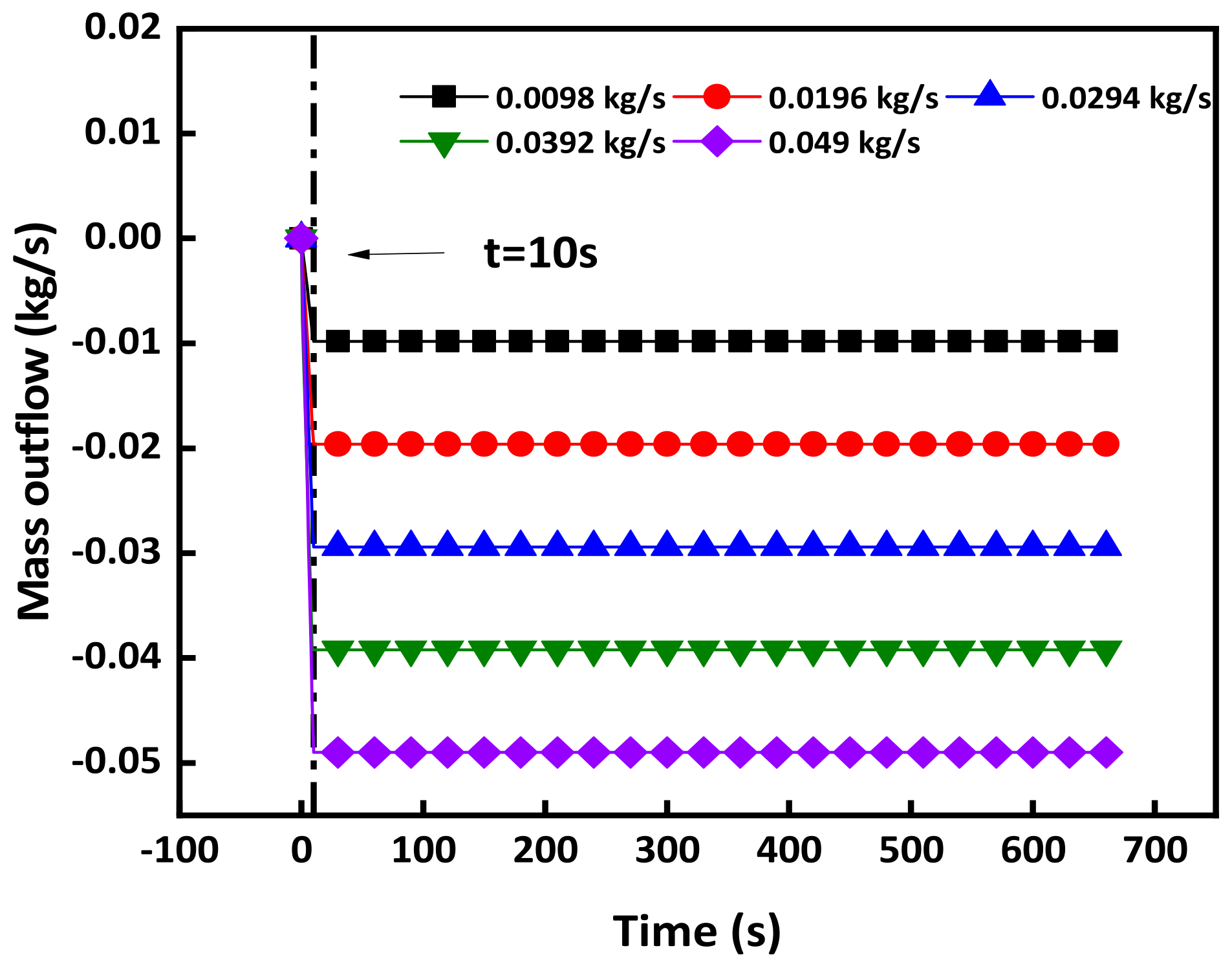
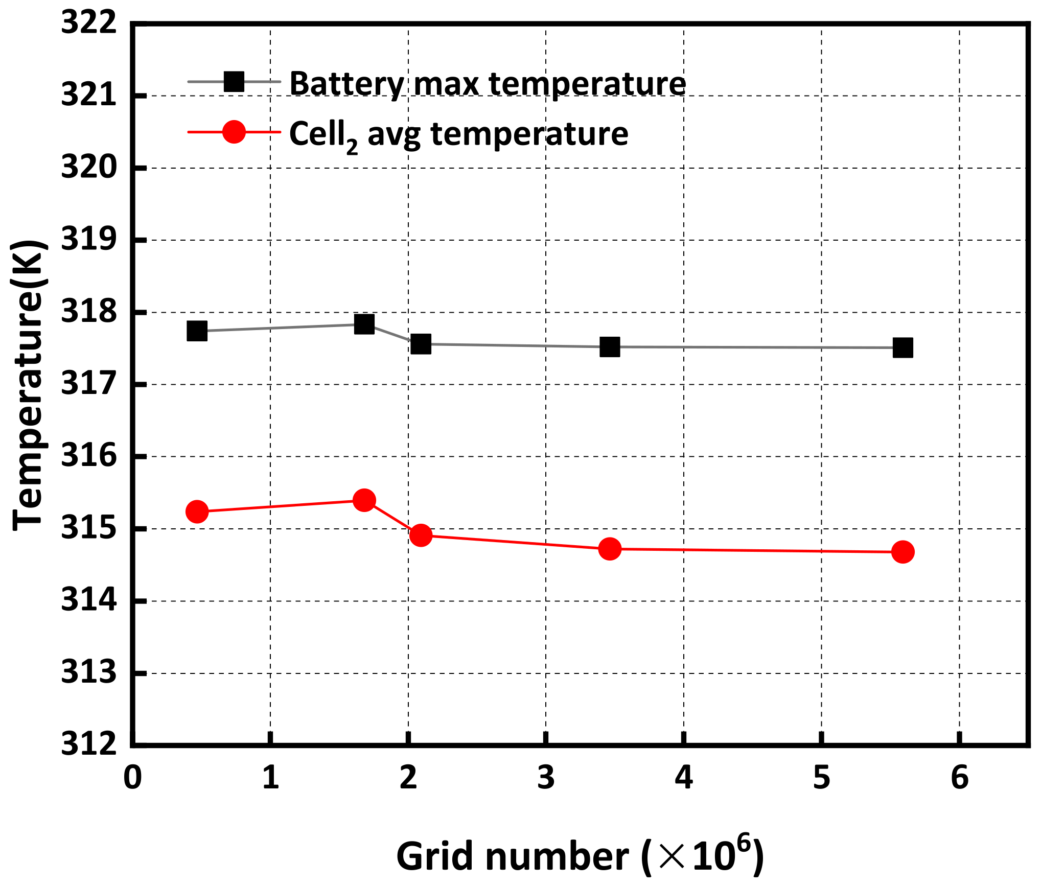
2.4. Sensitive Analysis

In order to obtain a reliable CFD solution, it is necessary to conduct a mesh independence analysis to assess the numerical errors and uncertainties. Mesh sensitivity analysis is a crucial step in the CFD simulation process. It involves investigating the influence of mesh refinement or coarsening on the simulation results to ensure that the numerical solution is both accurate and reliable [91]. In this study, the entire battery cell geometry was constructed, and the computational domain was discretized using an unstructured mesh, as depicted in Figure 7. Different mesh sizes were selected and compared at the same configuration and operation conditions. The sensitivity analysis was performed under an air-cooling system with a velocity of 0.0098 kg/s. By comparing different grid sizes and element numbers, it was observed that the maximum volume temperature and average temperature of the second cells reached a stable state when the grid count reached 2.09 million. In order to save the computational resources and improve the simulation efficiency, the first stable state is selected for the rest of the numerical analysis. Therefore, a mesh consisting of approximately 2.09 million elements was deemed appropriate for simulating this battery pack, as shown in Figure 4. With this unstructured mesh, the computational region was fully mapped, and the inflation layer connected the intersection between the battery surface and the air domain to analyze the heat transfer further. The whole working process is demonstrated considering the temperature increases.

3. Results and Discussion

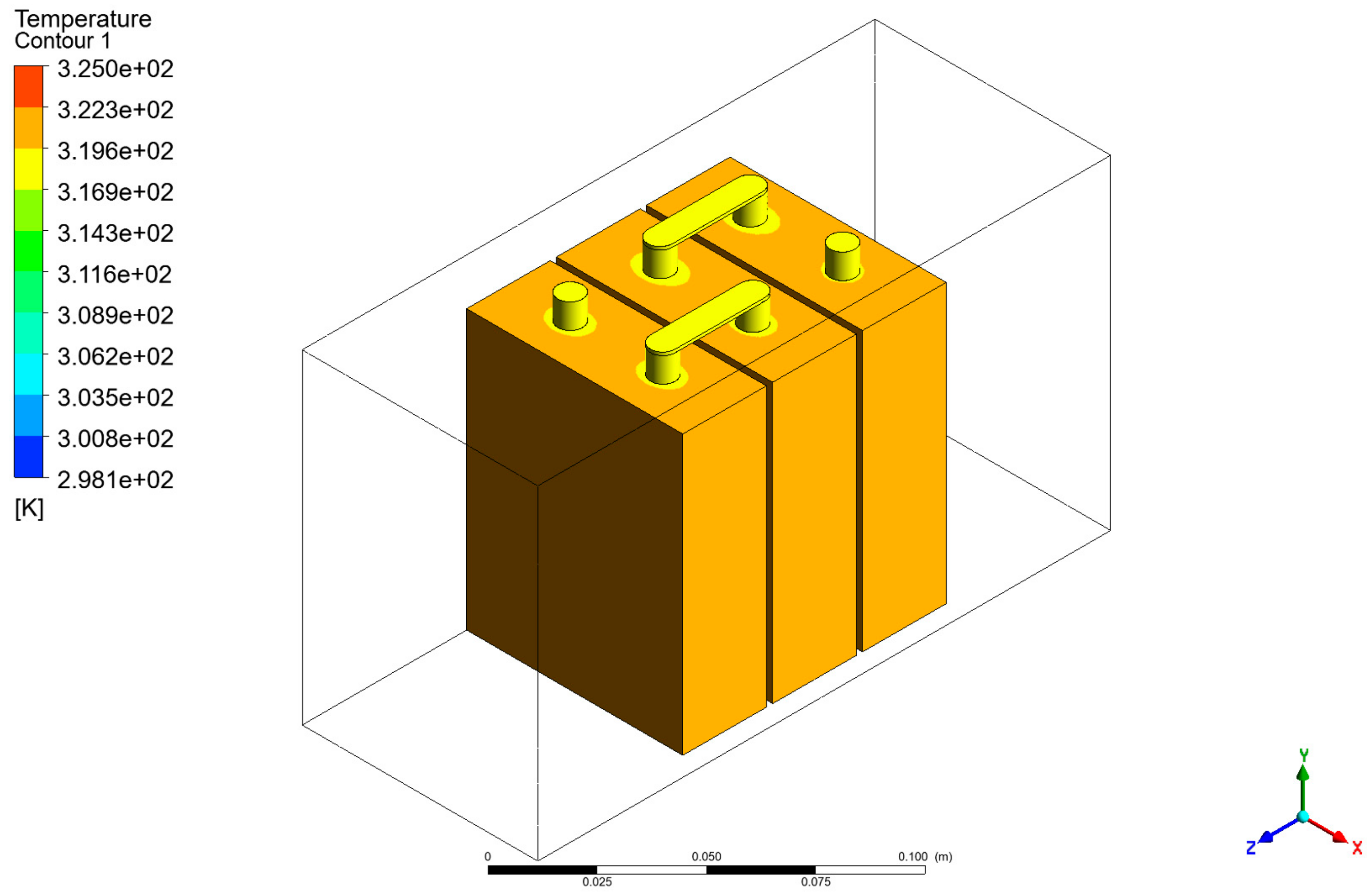
3.1. Battery Pack Simulation

In this work, the single-cell battery model was validated in Section 2.2. The coupled thermal-electrochemical model was also applied to the whole battery pack simulation. The temperature distribution of the battery pack alone is demonstrated in Figure 2 and the simulation of the air-cooling system added to the battery pack is shown in Figure 3. Figure 3 demonstrates two air-cooling directions under various air velocities. The temperature distributions of both the battery pack and the air domain were simulated and described in the Figure 1. Considering the normal operating conditions, the proposed model provided a comprehensive analysis of the temperature distribution for both the battery pack system and the ambient environment. The rest of the sections will investigate the other parameters affecting the cooling performance of the battery pack.

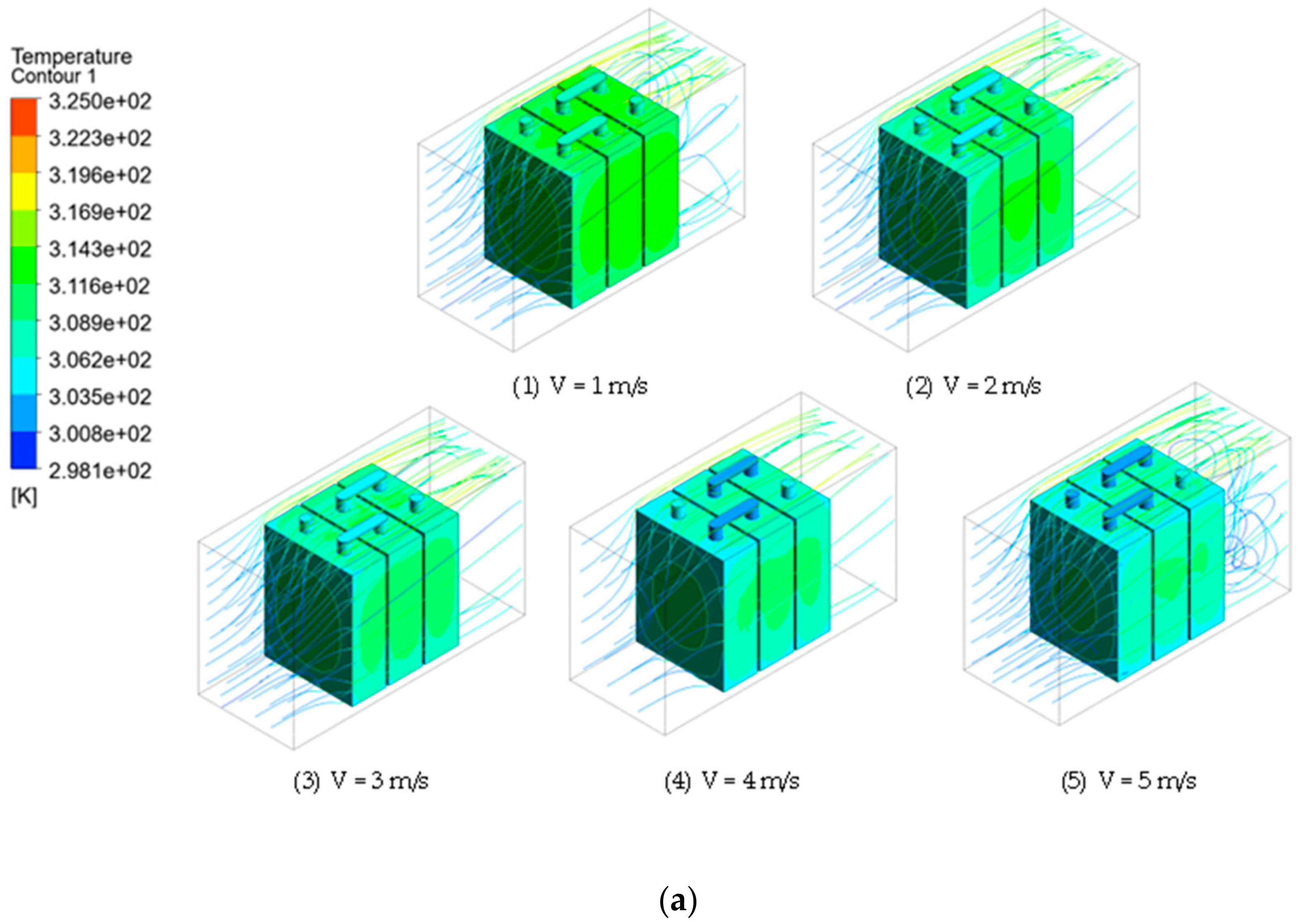
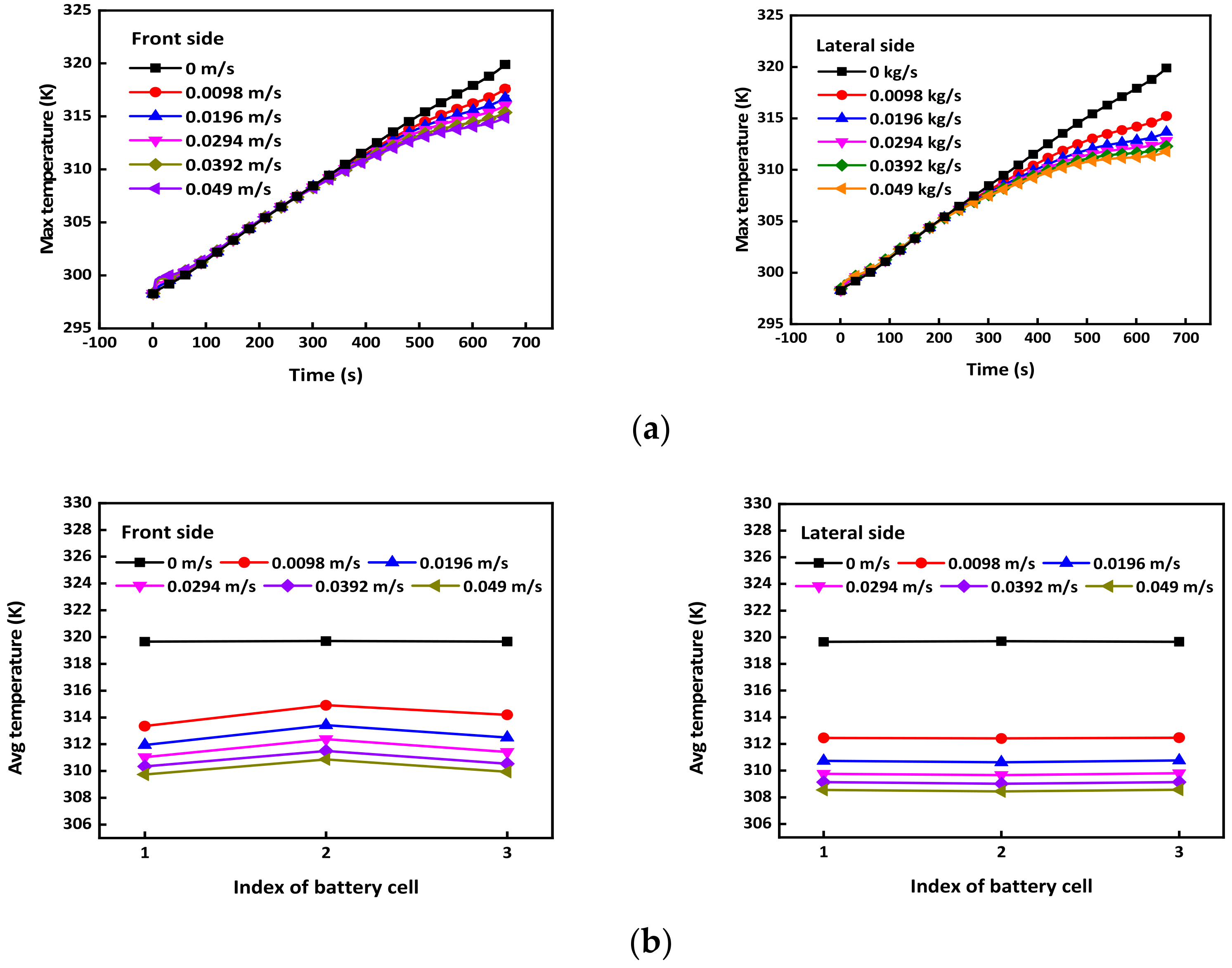
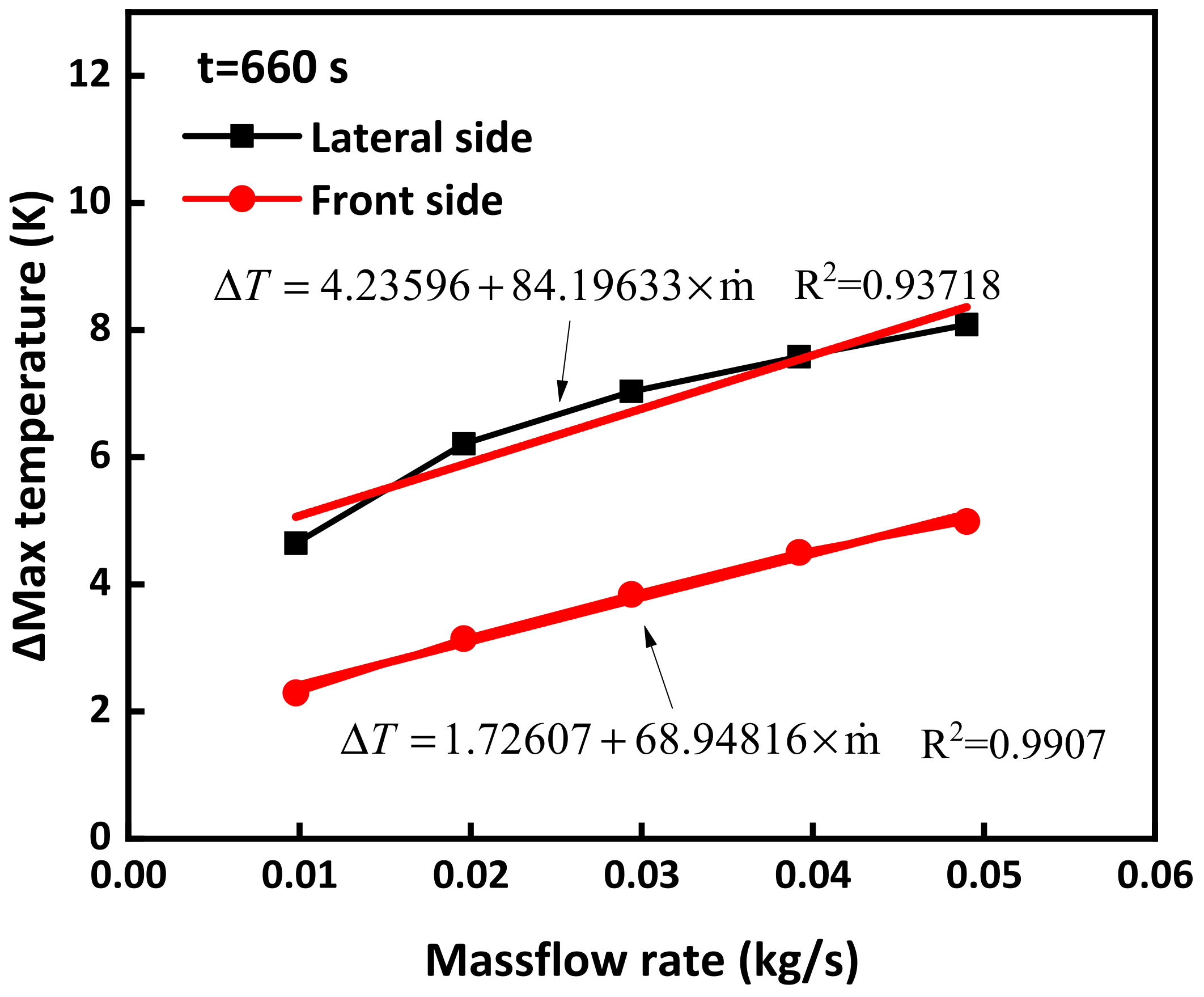
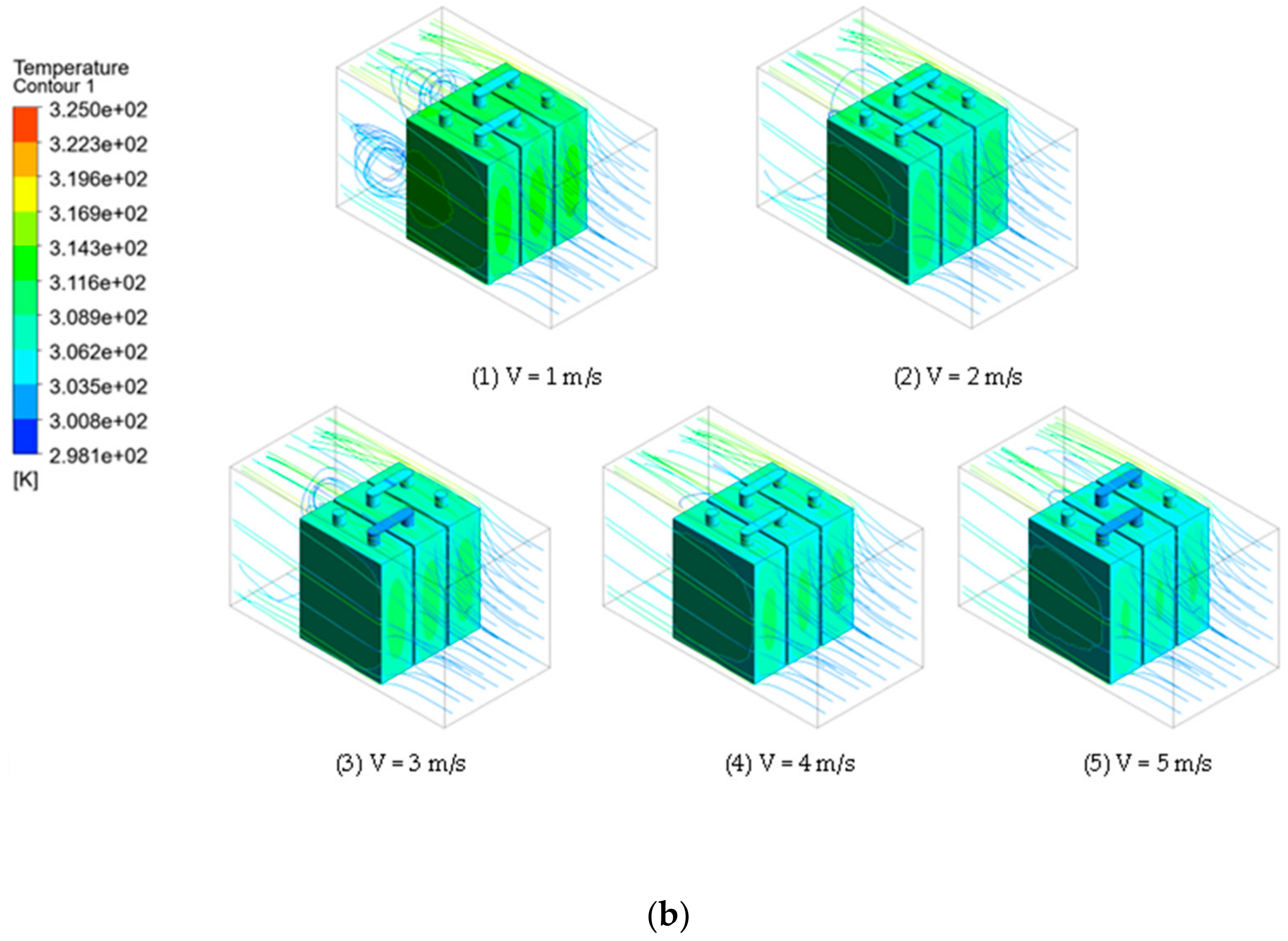
3.2. Air-Cooling Direction Effect

To investigate the influence of air-cooling direction on the temperature distribution of a battery pack, two distinct air-cooling directions and five different air inflow rates were selected for analysis, as outlined in Table 2. The accompanying Figure 8 illustrates the temperature distribution under varying air-cooling directions.
In the case of the front side direction, it is evident that the temperature distribution is characterized by a notable disparity. The average temperature in the second battery cell is observed to be higher compared with the remaining cells due to limited air circulation across the intercellular gaps. Also, the temperature of Cell 3 is slightly higher than the temperature of Cell 1. This is because the air cooled the first two cells, and the temperature was higher than its temperature was at the inlet. On the other side, when employing the lateral side direction, a more balanced temperature distribution is achieved, with all cells exhibiting nearly identical average temperatures. Furthermore, in the current two scenarios, the maximum temperature in the front side case is higher due to the cooled air being blocked by the front surface.
For the front side direction, the results demonstrate a linear increase in the maximum battery temperature from an initial value of 298.15 K to 319.8496 K over a 660-s duration. Furthermore, the behavior of the air-cooling system becomes apparent as the rate of temperature increase decelerates after approximately 350 s, primarily due to self-heating effects. Subsequently, after 660 s of air cooling, the maximum temperatures recorded in the battery are 317.55907 K, 316.7062 K, 316.00958 K, 315.3474 K, and 314.86001 K, corresponding to air-cooling velocities of 0.0098 kg/s, 0.0196 kg/s, 0.0294 kg/s, 0.0392 kg/s, 0.049 kg/s, respectively. In comparison, the lateral side direction exhibits a slower rate of temperature increase prior to the onset of self-heating, suggesting a more effective cooling mechanism. As depicted in Figure 9, the maximum temperatures in the battery after 660 s of air cooling are recorded as 315.20251 K, 313.6402 K, 312.8179 K, 312.26744 K, and 311.76327 K, corresponding to air-cooling velocities of 0.0098 kg/s, 0.0196 kg/s, 0.0294 kg/s, 0.0392 kg/s, 0.049 kg/s, respectively. The temperature difference for both scenarios is increased, while the lateral side direction performs a higher change, which means the lateral side direction has a more direct relationship between the mass flow rate and the cooled maximum battery temperature.
To further elucidate the air-cooling effect, a comprehensive analysis of the maximum temperature difference was conducted. Figure 9 presents the maximum temperature difference in 660 s between the absence of an air-cooling system and different air-cooling velocities. The findings demonstrate the superior performance of the lateral side direction in terms of air-cooling effectiveness compared with the front side direction. Consequently, an empirical formula is provided below to capture the observed relationship:
Lateral side with R2 = 0.93718:
Δ T = 4.23596 + 84.19633 × m ˙
Front side with R2 = 0.9907:
Δ T = 1.72607 + 68.94816 × m ˙
where Δ T is the temperature difference compared with the case under natural convection. m ˙ is the mass flow rate applied to the air-cooling system.
The reason for this different effectiveness is similar to the average temperature difference, which is that the cooled air is blocked by the front surface. Compared with the front side, the lateral side has a larger interface between the battery pack surface and the cooled air.

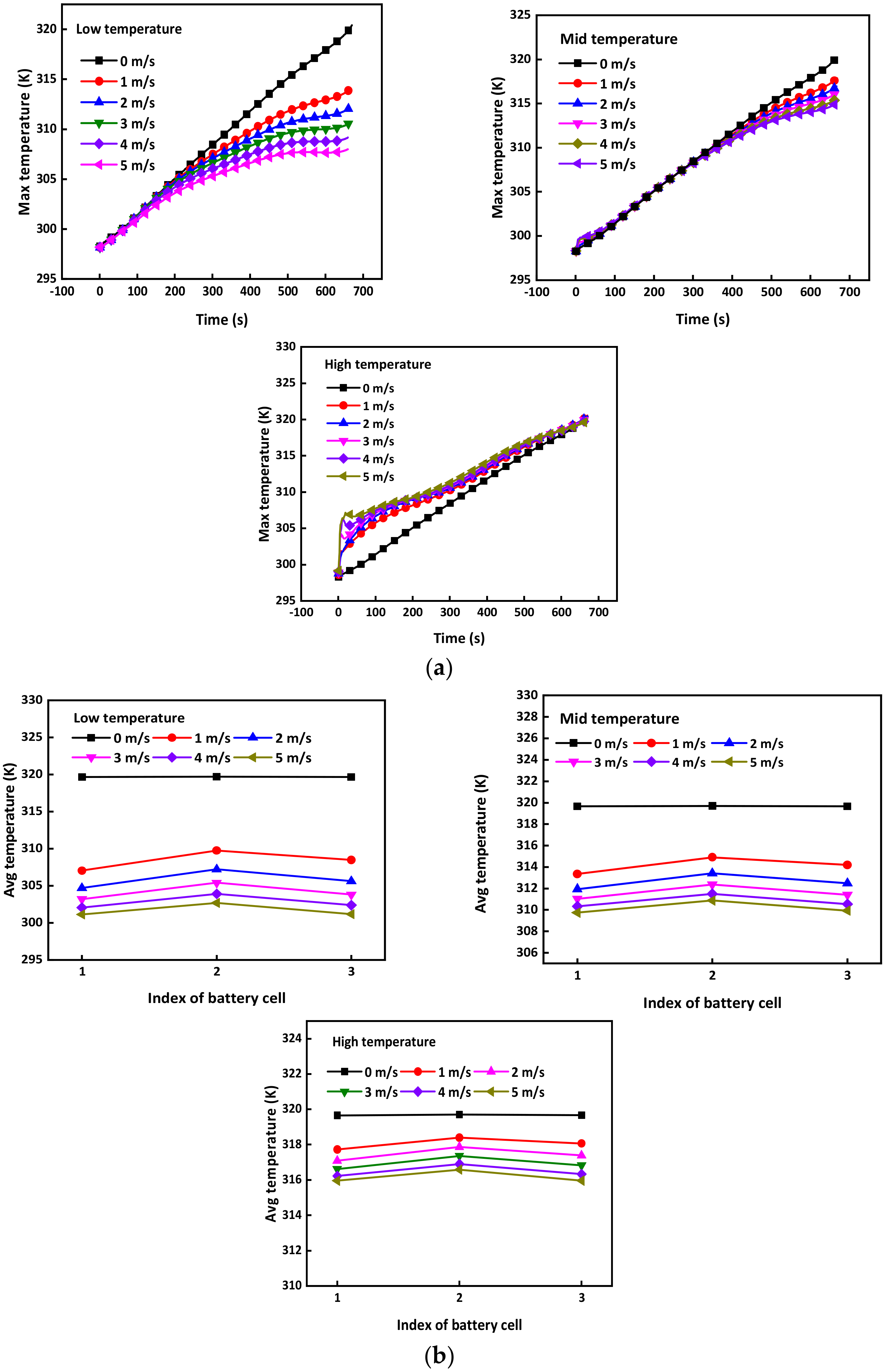
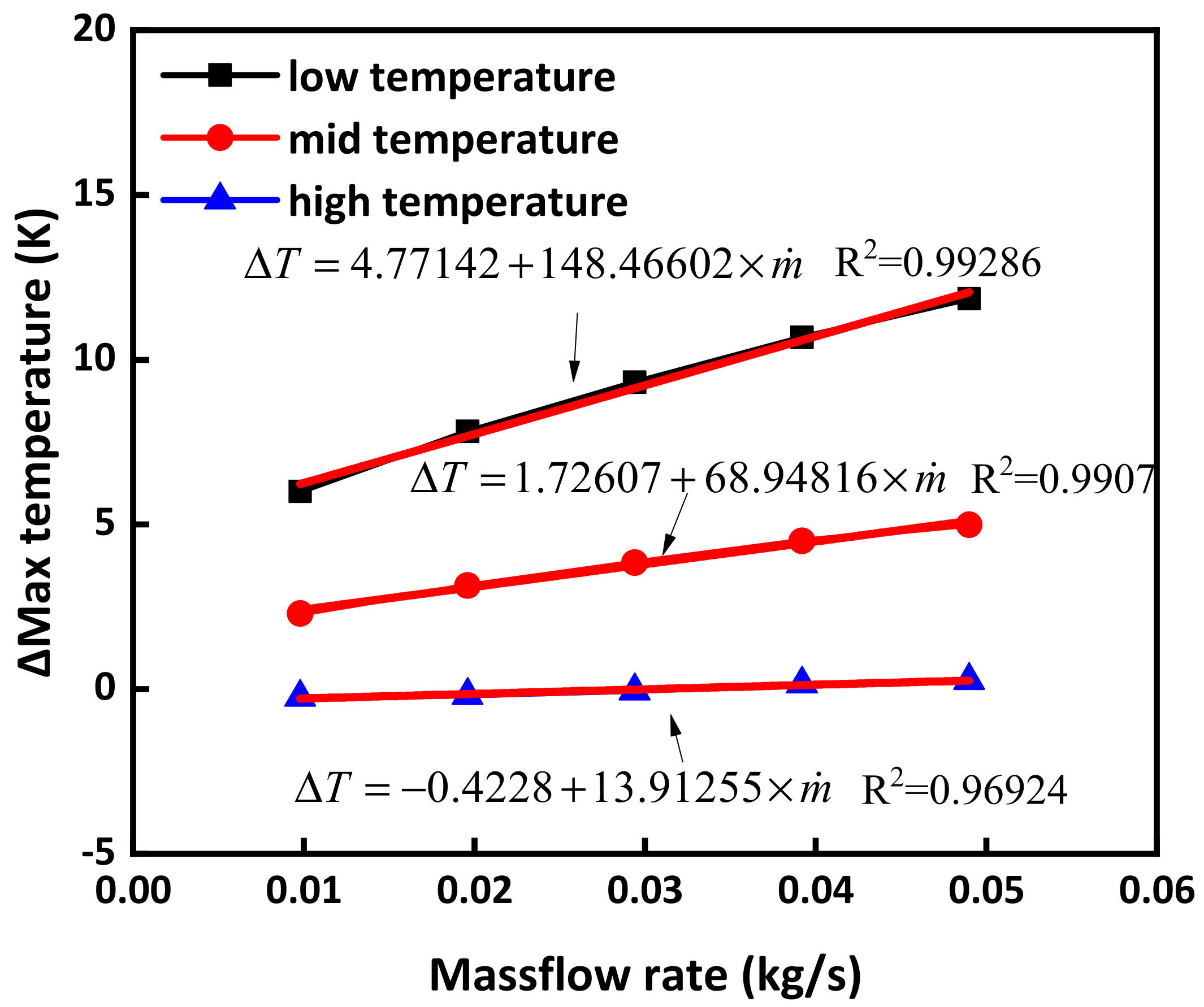
3.3. Air-Cooling Temperature Effect

To investigate the effect of air-cooling temperature, experiments were conducted using air-cooling systems at temperatures of 288.15 K, 300 K, and 308.15 K, with an ambient temperature of 298.15 K. Additionally, five different air-cooling velocities were employed for each air-cooling system. The experimental setup is summarized in Table 2.
Comparing different air-cooling directions, the temperature distribution on the front side exhibited similarities, with the highest average temperature observed in the middle cell, as shown in Figure 10. For an ambient temperature of 288.15 K, after 660 s of self-heating, the maximum temperature increased to 313.84743 K, 312.02179 K, 310.53007 K, 309.16718 K, and 307.9999 K, respectively, corresponding to air-cooling mass loss rates of 0.0098 kg/s, 0.0196 kg/s, 0.0294 kg/s, 0.0392 kg/s, and 0.049 kg/s. However, the growth of maximum temperature differed significantly. In the cases of air-cooling temperatures of 288.15 K and 300 K, the maximum temperature increased linearly without the air-cooling system, and the increase was relatively slow at 200 s and 400 s, respectively. Conversely, for an air-cooling temperature of 308.15 K, the maximum temperature rapidly rose to approximately 308.15 K within the first 100 s, resembling the heating effect. Moreover, after 660 s of self-heating, the maximum temperature increased to 320.09476 K, 320.04032 K, 319.90144 K, 319.69423 K, and 319.58609 K, corresponding to air-cooling mass loss rate of 0.0098 kg/s, 0.0196 kg/s, 0.0294 kg/s, 0.0392 kg/s, and 0.049 kg/s, respectively. In contrast, the maximum temperature without the air-cooling system was 319.8496 K.
Figure 11 illustrates the change in temperature difference with respect to the mass loss rate under different ambient temperatures. When the ambient temperature is low, the temperature difference is 6.00217 K at a mass flow rate of 0.0098 kg/s, while it increases to 11.8497 K at a mass flow rate of 0.049 kg/s. However, as the ambient temperature rises, the cooling effect of the battery significantly decreases with an increase in mass flow rate. When the ambient temperature increases to mid temperature, the temperature difference is 2.29053 K at a mass flow rate of 0.0098 kg/s, while it increases to 4.98959 K at a mass flow rate of 0.049 kg/s. It is evident that the cooling effect is not as pronounced as in the low ambient temperature. Moreover, when the temperature rises to a high temperature at a mass flow rate of 0.0098 kg/s, the temperature difference becomes −0.24516 K, indicating a situation where the cooling effect turns into a heating effect. This suggests that the air-cooling system was ineffective when the air-cooling temperature was 308.15 K. However, when the mass flow rate is increased to 0.049 kg/s, the temperature difference becomes 0.26351 K. Compared with the low and mid ambient temperatures, the cooling effect significantly decreases. From Figure 10, it can be observed that the maximum temperature of the battery is slightly lower than or slightly higher than the ambient temperature in both the 300 K and 288.15 K conditions. Therefore, the maximum temperature of the battery has a significant inhibitory effect. When the air-cooling temperature is higher than the ambient temperature, the initial effect of air cooling on the battery pack is actually heating. As the temperature of the battery pack rises to the temperature of the air-cooling system, the air-cooling system will start to function as intended, providing cooling as the temperature of the battery pack increases. An empirical formula is provided below to capture the observed relationship:
When the air-cooling temperature is 288.15 K with R2 = 0.99286
Δ T = 4.77142 + 148.46602 × m ˙
When the air-cooling temperature is 300 K with R2 = 0.9907
Δ T = 1.72607 + 68.94816 × m ˙
When the air-cooling temperature is 308.15 K with R2 = 0.96924
Δ T = 0.4228 + 13.91255 × m ˙
where Δ T is the temperature difference compared with the case under natural convection. m ˙ is the mass flow rate applied to the air-cooling system.

4. Conclusions

This study provides comprehensive data on the relationship between air-cooling efficiency and various factors affecting air cooling. Compared with traditional air-cooling system numerical simulations, this work takes into account different air-cooling temperatures, which are closer to actual conditions. In addition, compared with the configuration of traditional air-cooling systems, this paper also compares different air-cooling directions, providing that cooling effects are better on the lateral side, offering new ideas for the future development of air-cooling systems. The results indicate that air cooling from the lateral side is more effective than from the front side, as evidenced by the specific temperature distribution and maximum temperature difference. Moreover, it is crucial to note that the air-cooling system’s performance deteriorates when the air-cooling temperature exceeds 308.15 K. Therefore, it is recommended to develop a rated air-cooling temperature to prevent thermal runaway.
In order to better compare the efficiency of different air-cooling directions and temperatures, it is clear that an air-cooling system with the appropriate direction is more efficient than one with lower temperatures. The efficiency is demonstrated in the temperature distribution, which clearly shows an increase in temperature in the middle of the battery pack. Compared with traditional air-cooling systems like U-shape and Z-shape under front side air-cooling directions, the cooling system performs well using lateral side direction [54]. Therefore, battery designers should prioritize the air-cooling direction and its alignment with the battery pack to reduce the likelihood of thermal runaway in battery packs. Battery cooling systems are crucial components in electric vehicles and other applications where batteries are subjected to high loads, ensuring that the batteries operate within a safe temperature range. Effective cooling is essential for maintaining the performance, efficiency, and lifespan of the battery. The proposed methods and numerical data could be further applied in the battery pack optimization design and may be coupled with other methodologies, i.e., artificial neural network, to further enhance the battery thermal safety and reduce the battery fire risks. Furthermore, the proposed modelling process can be used for a different battery configuration, battery chemistry, and battery cooling systems.

Author Contributions

Conceptualization, W.L. and A.L.; methodology, W.L. and X.W.; software, Q.C.; validation, L.K.; formal analysis, I.M.D.C.C. and P.Y.C.; investigation, W.L. and X.W.; resources, P.L.; data curation, X.W. and Q.C.; writing—original draft preparation, W.L.; writing—review and editing, I.M.D.C.C. and P.Y.C.; visualization, W.L.; supervision, P.L. and A.L.; project administration, A.L.; funding acquisition, P.L. All authors have read and agreed to the published version of the manuscript.

Funding

This paper was funded by the National Natural Science Foundation of China (No. 71974161).

Institutional Review Board Statement

Not applicable.

Informed Consent Statement

Not applicable.

Data Availability Statement

Data are contained within the article.

Acknowledgments

The authors would like to recognize the support provided by Guan Yeoh from UNSW Sydney.

Conflicts of Interest

The authors declare no conflicts of interest.

References

  1. Zhang, J.; Zhang, L.; Sun, F.; Wang, Z. An Overview on Thermal Safety Issues of Lithium-ion Batteries for Electric Vehicle Application. IEEE Access 2018, 6, 23848–23863. [Google Scholar] [CrossRef]
  2. Ghiji, M.; Edmonds, S.; Moinuddin, K. A review of experimental and numerical studies of lithium ion battery fires. Appl. Sci. 2021, 11, 1247. [Google Scholar] [CrossRef]
  3. Lai, X.; Yao, J.; Jin, C.; Feng, X.; Wang, H.; Xu, C.; Zheng, Y. A review of lithium-ion battery failure hazards: Test standards, accident analysis, and safety suggestions. Batteries 2022, 8, 248. [Google Scholar] [CrossRef]
  4. Li, A.; Weng, J.; Yuen, A.C.Y.; Wang, W.; Liu, H.; Lee, E.W.M.; Wang, J.; Kook, S.; Yeoh, G.H. Machine learning assisted advanced battery thermal management system: A state-of-the-art review. J. Energy Storage 2023, 60, 106688. [Google Scholar] [CrossRef]
  5. Doughty, D.H.; Roth, E.P. A General Discussion of Li Ion Battery Safety. Electrochem. Soc. Interface 2012, 21, 37. [Google Scholar]
  6. Yan, J.; Li, K.; Chen, H.; Wang, Q.; Sun, J. Experimental study on the application of phase change material in the dynamic cycling of battery pack system. Energy Convers. Manag. 2016, 128, 12–19. [Google Scholar] [CrossRef]
  7. Dubarry, M.; Devie, A. Battery durability and reliability under electric utility grid operations: Representative usage aging and calendar aging. J. Energy Storage 2018, 18, 185–195. [Google Scholar] [CrossRef]
  8. Sun, J.; Mao, B.; Wang, Q. Progress on the research of fire behavior and fire protection of lithium ion battery. Fire Saf. J. 2021, 120, 103119. [Google Scholar] [CrossRef]
  9. Lystianingrum, V.; Priyadi, A.; Negara, I.M.Y. Lessons learned from large-scale lithium-ion battery energy storage systems incidents: A mini review. Process Saf. Prog. 2023, 42, 348–355. [Google Scholar] [CrossRef]
  10. Singh, V.K.; Shalu; Balo, L.; Gupta, H.; Singh, S.K.; Singh, R.K. Solid polymer electrolytes based on Li+/ionic liquid for lithium secondary batteries. J. Solid State Electrochem. 2017, 21, 1713–1723. [Google Scholar] [CrossRef]
  11. Balo, L.; Gupta, H.; Singh, S.K.; Singh, V.K.; Tripathi, A.K.; Srivastava, N.; Tiwari, R.K.; Mishra, R.; Meghnani, D.; Singh, R.K. Development of gel polymer electrolyte based on LiTFSI and EMIMFSI for application in rechargeable lithium metal battery with GO-LFP and NCA cathodes. J. Solid State Electrochem. 2019, 23, 2507–2518. [Google Scholar] [CrossRef]
  12. Wu, Z.-H.; Wu, Y.; Tang, Y.; Jiang, J.-C.; Huang, A.-C. Evaluation of composite flame-retardant electrolyte additives improvement on the safety performance of lithium-ion batteries. Process Saf. Environ. Prot. 2023, 169, 285–292. [Google Scholar] [CrossRef]
  13. Zhang, C.-Z.; Xie, L.-J.; Tang, Y.; Li, Y.; Jiang, J.-C.; Huang, A.-C. Thermal Safety Evaluation of Silane Polymer Compounds as Electrolyte Additives for Silicon-Based Anode Lithium-Ion Batteries. Processes 2022, 10, 1581. [Google Scholar] [CrossRef]
  14. Li, X.; Zhao, J.; Yuan, J.; Duan, J.; Liang, C. Simulation and analysis of air cooling configurations for a lithium-ion battery pack. J. Energy Storage 2021, 35, 102270. [Google Scholar] [CrossRef]
  15. Song, Y.; Sheng, L.; Wang, L.; Xu, H.; He, X. From separator to membrane: Separators can function more in lithium ion batteries. Electrochem. Commun. 2021, 124, 106948. [Google Scholar] [CrossRef]
  16. Li, A.; Yuen, A.C.Y.; Wang, W.; Weng, J.; Yeoh, G.H. Numerical investigation on the thermal management of lithium-ion battery system and cooling effect optimization. Appl. Therm. Eng. 2022, 215, 118966. [Google Scholar] [CrossRef]
  17. Bicy, K.; Gueye, A.B.; Rouxel, D.; Kalarikkal, N.; Thomas, S. Lithium-ion battery separators based on electrospun PVDF: A review. Surf. Interfaces 2022, 31, 101977. [Google Scholar] [CrossRef]
  18. Li, A.; Yuen, A.C.Y.; Wang, W.; Weng, J.; Lai, C.S.; Kook, S.; Yeoh, G.H. Thermal Propagation Modelling of Abnormal Heat Generation in Various Battery Cell Locations. Batteries 2022, 8, 216. [Google Scholar] [CrossRef]
  19. De Cachinho Cordeiro, I.M.; Li, A.; Lin, B.; Ma, D.X.; Xu, L.; Eh, A.L.-S.; Wang, W. Solid Polymer Electrolytes for Zinc-Ion Batteries. Batteries 2023, 9, 343. [Google Scholar] [CrossRef]
  20. Li, A.; Yuen, A.C.Y.; Wang, W.; Chen, T.B.Y.; Lai, C.S.; Yang, W.; Wu, W.; Chan, Q.N.; Kook, S.; Yeoh, G.H. Integration of Computational Fluid Dynamics and Artificial Neural Network for Optimization Design of Battery Thermal Management System. Batteries 2022, 8, 69. [Google Scholar] [CrossRef]
  21. Wang, H.; He, F.; Ma, L. Experimental and modeling study of controller-based thermal management of battery modules under dynamic loads. Int. J. Heat Mass Transf. 2016, 103, 154–164. [Google Scholar] [CrossRef]
  22. Zhang, S.-B.; He, X.; Long, N.-C.; Shen, Y.-J.; Gao, Q. Improving the air-cooling performance for lithium-ion battery packs by changing the air flow pattern. Appl. Therm. Eng. 2023, 221, 119825. [Google Scholar] [CrossRef]
  23. Xin, S.; Wang, C.; Xi, H. Thermal management scheme and optimization of cylindrical lithium-ion battery pack based on air cooling and liquid cooling. Appl. Therm. Eng. 2023, 224, 120100. [Google Scholar] [CrossRef]
  24. Satyanarayana, G.; Sudhakar, D.R.; Goud, V.M.; Ramesh, J.; Pathanjali, G. Experimental investigation and comparative analysis of immersion cooling of lithium-ion batteries using mineral and therminol oil. Appl. Therm. Eng. 2023, 225, 120187. [Google Scholar] [CrossRef]
  25. Panchal, S.; Dincer, I.; Agelin-Chaab, M.; Fraser, R.; Fowler, M. Experimental and theoretical investigations of heat generation rates for a water cooled LiFePO4 battery. Int. J. Heat Mass Transf. 2016, 101, 1093–1102. [Google Scholar] [CrossRef]
  26. Ren, R.; Zhao, Y.; Diao, Y.; Liang, L. Experimental study on the bottom liquid cooling thermal management system for lithium-ion battery based on multichannel flat tube. Appl. Therm. Eng. 2023, 219, 119636. [Google Scholar] [CrossRef]
  27. Li, P.; Zhao, J.; Zhou, S.; Duan, J.; Li, X.; Zhang, H.; Yuan, J. Design and Optimization of a Liquid Cooling Thermal Management System with Flow Distributors and Spiral Channel Cooling Plates for Lithium-Ion Batteries. Energies 2023, 16, 2196. [Google Scholar] [CrossRef]
  28. Zhao, G.; Wang, X.; Negnevitsky, M.; Li, C. An up-to-date review on the design improvement and optimization of the liquid-cooling battery thermal management system for electric vehicles. Appl. Therm. Eng. 2023, 219, 119626. [Google Scholar] [CrossRef]
  29. Hallaj, S.A.; Selman, J.R. A Novel Thermal Management System for Electric Vehicle Batteries Using Phase-Change Material. J. Electrochem. Soc. 2000, 147, 3231–3236. [Google Scholar] [CrossRef]
  30. Qi, X.; Sidi, M.O.; Tlili, I.; Ibrahim, T.K.; Elkotb, M.A.; El-Shorbagy, M.; Li, Z. Optimization and sensitivity analysis of extended surfaces during melting and freezing of phase changing materials in cylindrical Lithium-ion battery cooling. J. Energy Storage 2022, 51, 104545. [Google Scholar] [CrossRef]
  31. Weng, J.; Xiao, C.; Yang, X.; Ouyang, D.; Chen, M.; Zhang, G.; Waiming, E.L.; Yuen, R.K.K.; Wang, J. An energy-saving battery thermal management strategy coupling tubular phase-change-material with dynamic liquid cooling under different ambient temperatures. Renew. Energy 2022, 195, 918–930. [Google Scholar] [CrossRef]
  32. Mahmud, M.; Rahman, K.S.; Rokonuzzaman, M.; Habib, A.A.; Islam, M.R.; Motakabber, S.; Channumsin, S.; Chowdhury, S. Lithium-ion battery thermal management for electric vehicles using phase change material: A review. Results Eng. 2023, 20, 101424. [Google Scholar] [CrossRef]
  33. Yang, B.; Ji, J.; Zhang, X.; Hua, W. Passive cooling of lithium-ion batteries based on flexible phase change materials: Molecular structure, interactions and mechanistic aspects. J. Mol. Liq. 2023, 391, 123340. [Google Scholar] [CrossRef]
  34. Liang, J.; Gan, Y.; Li, Y. Investigation on the thermal performance of a battery thermal management system using heat pipe under different ambient temperatures. Energy Convers. Manag. 2018, 155, 1–9. [Google Scholar] [CrossRef]
  35. Chi, R.-G.; Chung, W.-S.; Rhi, S.-H. Thermal characteristics of an oscillating heat pipe cooling system for electric vehicle li-ion batteries. Energies 2018, 11, 655. [Google Scholar] [CrossRef]
  36. Behi, H.; Karimi, D.; Behi, M.; Jaguemont, J.; Ghanbarpour, M.; Behnia, M.; Berecibar, M.; Van Mierlo, J. Thermal management analysis using heat pipe in the high current discharging of lithium-ion battery in electric vehicles. J. Energy Storage 2020, 32, 101893. [Google Scholar] [CrossRef]
  37. Alihosseini, A.; Shafaee, M. Experimental study and numerical simulation of a Lithium-ion battery thermal management system using a heat pipe. J. Energy Storage 2021, 39, 102616. [Google Scholar] [CrossRef]
  38. Weragoda, D.M.; Tian, G.; Burkitbayev, A.; Lo, K.-H.; Zhang, T. A comprehensive review on heat pipe based battery thermal management systems. Appl. Therm. Eng. 2023, 224, 120070. [Google Scholar] [CrossRef]
  39. Mousavi, S.; Siavashi, M.; Zadehkabir, A. A new design for hybrid cooling of Li-ion battery pack utilizing PCM and mini channel cold plates. Appl. Therm. Eng. 2021, 197, 117398. [Google Scholar] [CrossRef]
  40. Faizan, M.; Pati, S.; Randive, P. Implications of novel cold plate design with hybrid cooling on thermal management of fast discharging lithium-ion battery. J. Energy Storage 2022, 53, 105051. [Google Scholar] [CrossRef]
  41. Singh, L.K.; Kumar, R.; Gupta, A.K.; Sharma, A.; Panchal, S. Computational study on hybrid air-PCM cooling inside lithium-ion battery packs with varying number of cells. J. Energy Storage 2023, 67, 107649. [Google Scholar] [CrossRef]
  42. Xin, Q.; Yang, T.; Zhang, H.; Yang, J.; Zeng, J.; Xiao, J. Experimental and numerical study of lithium-ion battery thermal management system using composite phase change material and liquid cooling. J. Energy Storage 2023, 71, 108003. [Google Scholar] [CrossRef]
  43. Faizan, M.; Pati, S.; Randive, P. Effect of channel configurations on the thermal management of fast discharging Li-ion battery module with hybrid cooling. Energy 2023, 267, 126358. [Google Scholar] [CrossRef]
  44. Akinlabi, A.H.; Solyali, D. Configuration, design, and optimization of air-cooled battery thermal management system for electric vehicles: A review. Renew. Sustain. Energy Rev. 2020, 125, 109815. [Google Scholar] [CrossRef]
  45. Zhao, G.; Wang, X.; Negnevitsky, M.; Zhang, H. A review of air-cooling battery thermal management systems for electric and hybrid electric vehicles. J. Power Sources 2021, 501, 230001. [Google Scholar] [CrossRef]
  46. Thakur, A.K.; Prabakaran, R.; Elkadeem, M.; Sharshir, S.W.; Arıcı, M.; Wang, C.; Zhao, W.; Hwang, J.-Y.; Saidur, R. A state of art review and future viewpoint on advance cooling techniques for Lithium–ion battery system of electric vehicles. J. Energy Storage 2020, 32, 101771. [Google Scholar] [CrossRef]
  47. Yuan, C. Thermal Safety Research of Cylindrical Lithium-Ion Battery Integrated System; University of Science and Technology of China: Hefei, China, 2022. [Google Scholar]
  48. Zhang, X.; Li, M.; Zhang, Y.; Wang, F.; Wu, K. Experimental and Numerical Investigation of Thermal Energy Management with Reciprocating Cooling and Heating Systems for Li-Ion Battery Pack. J. Energy Eng. 2018, 144, 04018039. [Google Scholar] [CrossRef]
  49. Mahamud, R.; Park, C. Reciprocating air flow for Li-ion battery thermal management to improve temperature uniformity. J. Power Sources 2011, 196, 5685–5696. [Google Scholar] [CrossRef]
  50. Liu, Y.-P.; Ouyang, C.-Z.; Jiang, Q.-B.; Liang, B. Design and parametric optimization of thermal management of lithium-ion battery module with reciprocating air-flow. J. Cent. South Univ. 2015, 22, 3970–3976. [Google Scholar] [CrossRef]
  51. Zhuang, W.; Liu, Z.; Su, H.; Chen, G. An intelligent thermal management system for optimized lithium-ion battery pack. Appl. Therm. Eng. 2021, 189, 116767. [Google Scholar] [CrossRef]
  52. He, F.; Wang, H.; Ma, L. Experimental demonstration of active thermal control of a battery module consisting of multiple Li-ion cells. Int. J. Heat Mass Transf. 2015, 91, 630–639. [Google Scholar] [CrossRef]
  53. Wang, S.; Li, K.; Tian, Y.; Wang, J.; Wu, Y.; Ji, S. Improved thermal performance of a large laminated lithium-ion power battery by reciprocating air flow. Appl. Therm. Eng. 2019, 152, 445–454. [Google Scholar] [CrossRef]
  54. Liu, Y.; Zhang, J. Self-adapting J-type air-based battery thermal management system via model predictive control. Appl. Energy 2020, 263, 114640. [Google Scholar] [CrossRef]
  55. Yun, K.-S.; Pai, S.J.; Yeo, B.C.; Lee, K.-R.; Kim, S.-J.; Han, S.S. Simulation protocol for prediction of a solid-electrolyte interphase on the silicon-based anodes of a lithium-ion battery: ReaxFF reactive force field. J. Phys. Chem. Lett. 2017, 8, 2812–2818. [Google Scholar] [CrossRef] [PubMed]
  56. Chen, T.; Yuen, A.; Lin, B.; Liu, L.; Lo, A.; Chan, Q.; Zhang, J.; Cheung, S.; Yeoh, G. Characterisation of pyrolysis kinetics and detailed gas species formations of engineering polymers via reactive molecular dynamics (ReaxFF). J. Anal. Appl. Pyrolysis 2021, 153, 104931. [Google Scholar] [CrossRef]
  57. Olou’ou Guifo, S.P.B.; Mueller, J.E.; van Duin, D.; Talkhoncheh, M.K.; van Duin, A.C.; Henriques, D.; Markus, T. Development and Validation of a ReaxFF Reactive Force Field for Modeling Silicon–Carbon Composite Anode Materials in Lithium-Ion Batteries. J. Phys. Chem. C 2023, 127, 2818–2834. [Google Scholar] [CrossRef]
  58. Cordeiro, I.M.D.C.; Chen, T.B.Y.; Yuen, A.C.Y.; Wang, C.; Chan, Q.N.; Zhang, J.; Yeoh, G.H. Pyrolysis and combustion characterisation of HDPE/APP composites via molecular dynamics and CFD simulations. J. Anal. Appl. Pyrolysis 2022, 163, 105499. [Google Scholar] [CrossRef]
  59. Chen, T.B.Y.; De Cachinho Cordeiro, I.M.; Yuen, A.C.Y.; Yang, W.; Chan, Q.N.; Zhang, J.; Cheung, S.C.P.; Yeoh, G.H. An Investigation towards Coupling Molecular Dynamics with Computational Fluid Dynamics for Modelling Polymer Pyrolysis. Molecules 2022, 27, 292. [Google Scholar] [CrossRef]
  60. Li, H.; Wang, X.; Huang, H.; Ning, J.; Li, A.; Tu, J. Numerical study on the effect of superheat on the steam ejector internal flow and entropy generation for MED-TVC desalination system. Desalination 2022, 537, 115874. [Google Scholar] [CrossRef]
  61. Yuen, A.C.Y.; De Cachinho Cordeiro, I.M.; Chen, T.B.Y.; Chen, Q.; Liu, H.; Yeoh, G.H. Multiphase CFD modelling for enclosure fires—A review on past studies and future perspectives. Exp. Comput. Multiph. Flow 2022, 4, 1–25. [Google Scholar] [CrossRef]
  62. Voigt, S.; Sträubig, F.; Kwade, A.; Zehfuß, J.; Knaust, C. An empirical model for lithium-ion battery fires for CFD applications. Fire Saf. J. 2023, 135, 1–12. [Google Scholar] [CrossRef]
  63. Liu, H.; De Cachinho Cordeiro, I.M.; Yuen, A.C.Y.; Wang, C.; Li, A.; Yeoh, G.H. Numerical modeling of wet steam infused fluid mixture for potential fire suppression applications. Exp. Comput. Multiph. Flow 2023, 5, 142–148. [Google Scholar] [CrossRef]
  64. Kapahi, A.; Alvarez-Rodriguez, A.; Kraft, S.; Conzen, J.; Lakshmipathy, S. A CFD based methodology to design an explosion prevention system for Li-ion based battery energy storage system. J. Loss Prev. Process Ind. 2023, 83, 105038. [Google Scholar] [CrossRef]
  65. McGrattan, K.; Miles, S. Modeling fires using computational fluid dynamics (CFD). In SFPE Handbook of Fire Protection Engineering; Springer: Berlin/Heidelberg, Germany, 2016; pp. 1034–1065. [Google Scholar]
  66. Wang, C.; Yuen, A.C.Y.; Chan, Q.N.; Chen, T.B.Y.; Yip, H.L.; Cheung, S.C.-P.; Kook, S.; Yeoh, G.H. Numerical study of the comparison of symmetrical and asymmetrical eddy-generation scheme on the fire whirl formulation and evolution. Appl. Sci. 2020, 10, 318. [Google Scholar] [CrossRef]
  67. De Cachinho Cordeiro, I.M.; Liu, H.; Yuen, A.C.Y.; Chen, T.B.Y.; Li, A.; Cao, R.F.; Yeoh, G.H. Numerical investigation of expandable graphite suppression on metal-based fire. Heat Mass Transf. 2022, 58, 65–81. [Google Scholar] [CrossRef]
  68. Thabari, J.A.; Maragkos, G.; Snegirev, A.; Merci, B. Numerical study of the impact of the EDC formulation and finite-rate chemistry mechanisms in CFD simulations of fire plumes. Fire Saf. J. 2023, 141, 103950. [Google Scholar] [CrossRef]
  69. Yuen, A.C.Y.; Chen, T.B.Y.; Yang, W.; Wang, C.; Li, A.; Yeoh, G.H.; Chan, Q.N.; Chan, M.C. Natural Ventilated Smoke Control Simulation Case Study Using Different Settings of Smoke Vents and Curtains in a Large Atrium. Fire 2019, 2, 7. [Google Scholar] [CrossRef]
  70. Liu, L.; Chen, T.B.Y.; Yuen, A.C.Y.; Doley, P.M.; Wang, C.; Lin, B.; Liang, J.; Yeoh, G.H. A systematic approach to formulate numerical kinetics for furnishing materials fire simulation with validation procedure using cone/FT-IR data. Heat Mass Transf. 2021, 1–19. [Google Scholar] [CrossRef]
  71. Yuen, A.C.Y.; Chen, T.B.Y.; Cordero, I.M.D.C.; Liu, H.; Li, A.; Yang, W.; Cheung, S.C.P.; Chan, Q.N.; Kook, S.; Yeoh, G.H. Developing a solid decomposition kinetics extraction framework for detailed chemistry pyrolysis and combustion modelling of building polymer composites. J. Anal. Appl. Pyrolysis 2022, 163, 105500. [Google Scholar] [CrossRef]
  72. Kobayashi, K.; Tomioka, S.; Takahashi, M.; Kodera, M. Reaction mechanism reduction for ethylene-fueled supersonic combustion CFD. CEAS Space J. 2023, 15, 1–22. [Google Scholar] [CrossRef]
  73. Dahiya, A.; Tao, H.; Lin, C.-C.; Lin, K.C. Skeletal kinetic mechanism for predicting formation of non-fuel hydrocarbons and soot in ethylene flames—A CFD approach. Fuel Process. Technol. 2023, 249, 107847. [Google Scholar] [CrossRef]
  74. Doley, P.M.; Yuen, A.C.Y.; Kabir, I.; Liu, L.; Wang, C.; Chen, T.B.Y.; Yeoh, G.H. Thermal Hazard and Smoke Toxicity Assessment of Building Polymers Incorporating TGA and FTIR—Integrated Cone Calorimeter Arrangement. Fire 2022, 5, 139. [Google Scholar] [CrossRef]
  75. Hossain, M.D.; Hassan, M.K.; Saha, S.; Yuen, A.C.Y.; Wang, C.; George, L.; Wuhrer, R. Thermal and Pyrolysis Kinetics Analysis of Glass Wool and XPS Insulation Materials Used in High-Rise Buildings. Fire 2023, 6, 231. [Google Scholar] [CrossRef]
  76. Xie, J.; Li, J.; Wang, J.; Jiang, J. Fire protection design of a lithium-ion battery warehouse based on numerical simulation results. J. Loss Prev. Process Ind. 2022, 80, 104885. [Google Scholar] [CrossRef]
  77. Chen, T.B.Y.; Yuen, A.C.Y.; Yeoh, G.H.; Yang, W.; Chan, Q.N. Fire risk assessment of combustible exterior cladding using a collective numerical database. Fire 2019, 2, 11. [Google Scholar] [CrossRef]
  78. Yuen, A.C.Y.; Chen, T.B.Y.; Li, A.; De Cachinho Cordeiro, I.M.; Liu, L.; Liu, H.; Lo, A.L.P.; Chan, Q.N.; Yeoh, G.H. Evaluating the fire risk associated with cladding panels: An overview of fire incidents, policies, and future perspective in fire standards. Fire Mater. 2021, 45, 663–689. [Google Scholar] [CrossRef]
  79. Chen, T.B.Y.; Yuen, A.C.Y.; De Cachinho Cordeiro, I.M.; Liu, H.; Cao, R.; Ellison, A.; Yeoh, G.H. In-Depth Assessment of Cross-Passage Critical Velocity for Smoke Control in Large-Scale Railway Tunnel Fires. Fire 2022, 5, 140. [Google Scholar] [CrossRef]
  80. Yuen, A.C.Y.; Chen, T.B.Y.; Wang, C.; Wei, W.; Kabir, I.; Vargas, J.B.; Chan, Q.N.; Kook, S.; Yeoh, G.H. Utilising genetic algorithm to optimise pyrolysis kinetics for fire modelling and characterisation of chitosan/graphene oxide polyurethane composites. Compos. Part B Eng. 2020, 182, 107619. [Google Scholar] [CrossRef]
  81. De Cachinho Cordeiro, I.M.; Liu, H.; Yuen, A.C.Y.; Chen, T.B.Y.; Li, A.; Wang, C.; Cao, R.; Yeoh, G.H. On the Large Eddy Simulation modelling of water suppression systems droplet impact and coverage area. Fire 2022, 5, 165. [Google Scholar] [CrossRef]
  82. Wang, Z.J.; Fidkowski, K.; Abgrall, R.; Bassi, F.; Caraeni, D.; Cary, A.; Deconinck, H.; Hartmann, R.; Hillewaert, K.; Huynh, H.T. High-order CFD methods: Current status and perspective. Int. J. Numer. Methods Fluids 2013, 72, 811–845. [Google Scholar] [CrossRef]
  83. Yuen, A.C.Y.; Yeoh, G.H. Numerical Simulation of an Enclosure Fire in a Large Test Hall. Comput. Therm. Sci. 2013, 5, 459–471. [Google Scholar] [CrossRef]
  84. De Cachinho Cordeiro, I.M.; Liu, H.; Yuen, A.C.Y.; Chen, T.B.Y.; Li, A.; Yeoh, G.H. Numerical assessment of LES subgrid-scale turbulence models for expandable particles in fire suppression. Exp. Comput. Multiph. Flow 2021, 5, 99–110. [Google Scholar] [CrossRef]
  85. Ji, G.; Zhang, M.; Lu, Y.; Dong, J. The basic theory of CFD governing equations and the numerical solution methods for reactive flows. In Computational Fluid Dynamics—Recent Advances, New Perspectives and Applications; InTech: Berlin, Germany, 2023. [Google Scholar]
  86. Yuen, A.; Yeoh, G.; Yuen, R.; Chen, T. Numerical simulation of a ceiling jet fire in a large compartment. Procedia Eng. 2013, 52, 3–12. [Google Scholar]
  87. Azmi, W.; Sharma, K.; Sarma, P.; Mamat, R.; Najafi, G. Heat transfer and friction factor of water based TiO2 and SiO2 nanofluids under turbulent flow in a tube. Int. Commun. Heat Mass Transf. 2014, 59, 30–38. [Google Scholar] [CrossRef]
  88. Yuen, A.; Yeoh, G.; Timchenko, V.; Barber, T. LES and multi-step chemical reaction in compartment fires. Numer. Heat Transf. Part A Appl. 2015, 68, 711–736. [Google Scholar] [CrossRef]
  89. Hasan, H.A.; Togun, H.; Mohammed, H.I.; Abed, A.M.; Homod, R.Z. CFD simulation of effect spacing between lithium-ion batteries by using flow air inside the cooling pack. J. Energy Storage 2023, 72, 108631. [Google Scholar] [CrossRef]
  90. Wu, W.; Wu, W.; Wang, S. Thermal management optimization of a prismatic battery with shape-stabilized phase change material. Int. J. Heat Mass Transf. 2018, 121, 967–977. [Google Scholar] [CrossRef]
  91. Garcia, A.; Monsalve-Serrano, J.; Sari, R.L.; Martínez-Boggio, S. Thermal runaway evaluation and thermal performance enhancement of a lithium-ion battery coupling cooling system and battery sub-models. Appl. Therm. Eng. 2022, 202, 117884. [Google Scholar] [CrossRef]
Figure 4. Schematic of the computational battery mesh.
Fire 07 00029 g004
Figure 5. Numerical model validation; the error bar is 0.5%.
Fire 07 00029 g005
Figure 6. Mass outflow with time.
Fire 07 00029 g006
Figure 7. Mesh independence analysis.
Fire 07 00029 g007
Figure 8. (a) Flow rates in different directions; (b)temperature of different battery cells.
Fire 07 00029 g008
Figure 9. Relationship between max temperature difference and mass flow rate.
Fire 07 00029 g009
Figure 10. (a) Flow rates in different directions; (b) temperature of different battery cells.
Fire 07 00029 g010
Figure 11. Relationship between max temperature difference and mass flow rate.
Fire 07 00029 g011
Table 1. Properties of battery component.
NomenclatureParametersValue
Specific heat of negative tabCpn (J kg−1 K−1)871
Density of negative tab ρ n (kg m−3)2719
Thermal conductivity of negative tabKn (W m−1 K−1)202.4
Specific heat of positive tab/busbarCpp (J kg−1 K−1)381
Density of positive tab/busbar ρ p (kg m−3)8978
Thermal conductivity of positive tab/busbarkp (W m−1 K−1)387.6
Specific heat of cellCpc (J kg−1 K−1)950
Density of cell ρ c (kg m−3)2335
Thermal conductivity of cellkx, ky, kz (W m−1 K−1)2.6, 2.6, 0.9
Table 2. Different working conditions.
No.Air-cooling DirectionAir-Cooling Temperature (K)Airflow Rate (kg/s)
I-1Lateral3000.0098
I-20.0196
I-30.0294
I-40.0392
I-50.049
II-1Front3000.0098
II-20.0196
II-30.0294
II-40.0392
II-50.049
III-1Front288.150.0098
III-20.0196
III-30.0294
III-40.0392
III-50.049
IV-1Front308.150.0098
IV-20.0196
IV-30.0294
IV-40.0392
IV-50.049
Disclaimer/Publisher’s Note: The statements, opinions and data contained in all publications are solely those of the individual author(s) and contributor(s) and not of MDPI and/or the editor(s). MDPI and/or the editor(s) disclaim responsibility for any injury to people or property resulting from any ideas, methods, instructions or products referred to in the content.

