Abstract
The soot produced by fossil fuel combustion affects climate and human health, and the ethylene laminar flame is a crucial research object of soot generation. After verifying the accuracy of the numerical calculation model by comparing experimental data, the impact of changes in inlet flow rate and fuel flow composition operating conditions on the generation of soot were compared and analyzed. The calculated results obtained are consistent with the experimental data in terms of distribution trend. The deviation of the calculated peak integral smoke volume fraction is only 5%. Under the operating conditions set in this study, increasing the volume flow rate of the accompanying air will increase the volume fraction of soot generated by the ethylene laminar diffusion flame. Increasing the fuel volume flow rate will first increase and then decrease the volume fraction of soot.
1. Introduction
Emissions from the burning of fossil fuels greatly affect air quality, the environment, climate, and human health. Soot particles in emissions can significantly contribute to climate change [1,2] and are the leading global health hazard factor [3]. Studies have shown that exposure to environments with higher concentrations of soot significantly increases the risk of respiratory and cardiovascular diseases [4]. It is of great significance to study the principle and inhibition of pollutants produced by fossil fuel combustion. Ethylene is a crucial intermediate product in the combustion and pyrolysis of macromolecular hydro-carbon fuels, and an important precursor of polycyclic aromatic hydrocarbons and soot particles. The variation of oxygen concentration during coaxial jet diffusion combustion can affect the generation and emission of soot. Therefore, studying the change of oxygen concentration during ethylene combustion will help to better understand the mechanism of soot particles. Jerez et al. [5] numerically studied the ability of soot generation in ethylene laminar coaxial jet diffusion flames by using a segmented particle dynamics soot model based on polycyclic aromatic hydrocarbons. The results showed that as the oxygen index increased, the soot generation rate did not change, but the soot oxidation rate increased. Wang et al. [6] used the CoFlame [7] code to numerically study the influence of oxygen concentration on the flame structure, temperature field, smoke volume fraction distribution, and smoke formation process in a two-dimensional axisymmetric C2H4 diffusion flame in an O2-CO2 atmosphere. They concluded that as the oxygen concentration increased, the temperature peak, polycyclic aromatic hydrocarbon concentration, and smoke nucleation rate of the flame increased in a logarithmic relationship, whereas as the peak volume fraction of smoke increased, the surface growth rate, and oxidation rate of soot increased exponentially, while the flame height decreased logarithmically.
In recent years, there have been numerical studies on ethylene laminar coaxial jet diffusion flames domestically and internationally, as well as research on computational models, including radiation models and soot models [8]. Jerez et al. [9] studied the volume fraction, temperature, and distribution of polycyclic aromatic hydrocarbons in ethylene laminar non-premixed flames through experiments and numerical methods and compared the numerical simulation results with experimental results. The numerical simulation section was conducted using the CoFlame [6] code, and the soot model used a segmented model. It has been proven that there is an interaction between the decrease in temperature, the increase in smoke volume fraction, and the change in radiation heat transfer distribution as the fuel flow rate increases. Zimmer et al. [10] designed a low-cost smoke calculation method and applied it to the numerical simulation of ethylene/air coaxial jet diffusion flames under nine different operating conditions. For the first time, this framework was used to predict the entire smoke distribution field. All numerical work was completed using MATLAB R2018a software. Good prediction results were achieved. Zimmer et al. [11] evaluated the generation and radiative heat transfer process of soot under different model approximations in the numerical simulation study of ethylene laminar coaxial jet flames. Using Fluent16.1 software for numerical simulation, the soot model uses a semiempirical model based on acetylene. The results indicate that the selection of radiation models has a significant impact on the prediction of smoke concentration.
In addition, adding gas additives to fuel flow or wake air will have an impact on the production of soot. The commonly used gas additives in current research include CO2 [5], H2O [12], N2, and H2 [13,14,15]. The consideration of N2, CO2, and water as dilution gases is due to their association with flue gas recirculation in clean combustion technology, which can control the emissions of soot and nitrogen oxides [16,17]. Part of the research focuses on H2 because it is a very clean energy carrier, and its complete combustion does not produce carbon emissions.
In this study, the commercial software Fluent is used as the computing platform, and functions that cannot be realized by the software are redeveloped in order to establish a calculation model that can correctly react with the formation of soot in the laminar coaxial jet diffusion flame of ethylene. The effects of fuel flow, accompanying air, and gas additive mixing on the generation of soot are also analyzed. This paper can deepen the understanding of the combustion and smoke emission characteristics of ethylene and provide theoretical guidance for achieving pollutant emission control and achieving higher thermal efficiency in engineering practice.
2. Numerical Model Establishment
2.1. Simplification of Chemical Kinetics Model
Based on previous research, Ranzi et al. [18] developed a detailed reaction mechanism model, the CRECK model, for C1-C16 hydrocarbon oxidation. This model is hierarchical and modular and contains more than 8000 elementary reactions and more than 250 components. The mechanism was verified by measuring the laminar flame propagation velocity of many different burners and working conditions, including one-dimensional burner steady flame, opposed flame, expanded spherical flame, and Bunsen burner flame. The CRECK model is constantly updated and revised. Currently, the complete mechanism model includes 17,790 elementary reactions involving 492 components, and the C1-C3 hydrocarbon oxidation model, applicable to ethylene, includes 1999 elementary reactions involving 114 components.
Considering that the detailed chemical reaction mechanism model has a large number of components and reaction numbers, consumes significant computational resources, and converges slowly, this study begins with the CRECK model in an attempt to simplify it and verify its accuracy.
The commonly used methods for simplifying reaction mechanism models include Path Flux Analysis method [19], Direct Relationship Graph method [20], Sensitivity Analysis method [21], etc. In the process of mechanism simplification, the scale of the mechanism model can be minimized as much as possible within the preset allowable deviation range through joint or cross implementation of different methods. Chemkin software can simplify the mechanism model based on numerical calculations using the Reaction Workbench module. The simplified approach chosen in this study and the corresponding mechanism model scale are shown in Figure 1. The DRGEP method is a direct relational graph method with error propagation.

Figure 1.
Mechanism model simplifies the process.
The target groups selected in this study are divided into C2H2, C2H4, CH, CH2O, CH4, CO, CO2, H2O, N2, O2, and OH, and the allowable relative deviation of their peak molar fraction is set at 10%. In addition, to ensure the accuracy of the subsequent flow field and temperature field calculation, the allowable relative deviation of the axial velocity, flame propagation velocity, mass density, and temperature at the exit are set at 10%.
The resulting simplified mechanism is composed of 49 components and 640 primitive reactions, which is later named the CRECK-RED49 model in this study. To verify the accuracy of the simplified model, the calculation results of the CRECK-RED49 model and the CRECK model were compared in the response model evaluation section of Section 2.
Figure 2 shows a comparison of the results of ignition delay calculated using the CRECk-Red49 model (solid line) and the CRECK model (line) with the experimental study of Kopp et al. [22] as reference for the setting of working conditions, with N2 as dilution gas, close to atmospheric pressure, and an equivalent ratio of 1. The numerical results of the simplified model and the detailed model are basically consistent, with a maximum deviation of 6%, except for the high calculation of ignition delay at low temperature.
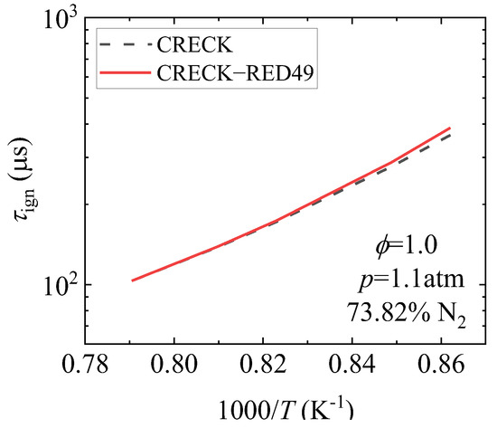
Figure 2.
Comparison of ignition delay period of simplified mechanism model.
Figure 3 shows a comparison of the results of laminar flame propagation velocity calculated using the CRECk-Red49 model (solid line) and the CRECK model (line) with reference to the experimental study of van Treek et al. [23] at 1 atm pressure and an equivalent ratio range of 0.5–2.5. It can be seen from the figure that the calculation results of the simplified model and the detailed model are very consistent. Only when the flame propagation velocity is near the peak and the equivalent ratio is above two in the fuel-rich condition, the calculation results of the simplified mechanism are slightly higher, but the maximum deviation is 1%.
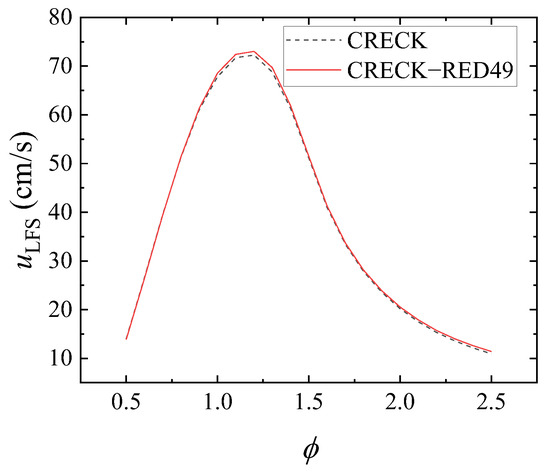
Figure 3.
Comparison of laminar flame propagation velocity in simplified mechanism model.
Figure 4 shows the change of (a) C2H4, (b) CO, (c) CH4, (d) C2H2, and (e) CO2 mole fraction with temperature under the working condition of 1atm pressure and 1 equivalence ratio calculated by creck-red49 model (solid line) and CRECK model (scribed line) in the experimental study of jet stirred reactor by Le Cong et al. [24]. Although the simplified model has some deviations in the calculation of the generated concentration of each component when compared to the detailed model, the deviation of the peak molar fraction of C2H2 with the largest molar fraction deviation is 15%, which is acceptable compared with the improvement of the calculation efficiency of the simplified model.
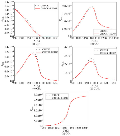
Figure 4.
Simplified Mechanism Specific Component Generation Concentration Comparison.
The simplified CRECK-RED49 model has some deviations when compared to the CRECK model during the calculation process, which reduces the computational accuracy. However, the number of components needing to be considered is reduced from 114 to 49, and the number of component conservation equations to be solved is reduced by 65, which significantly improves the computational efficiency of the component Transitive model in Fluent.
2.2. Calculation Domain, Grid, and Boundary Conditions
This study uses the geometric structure of Santoro burner [25] for numerical modeling. The influence of turbulent pulsation is ignored because the flame is a laminar flame, and the flame is simplified as a two-dimensional axisymmetric model. The calculation domain size is z × r = 150 mm × 51 mm, where z represents the axial direction and r represents the radial direction, as shown in Figure 5.

Figure 5.
Calculation Domain and Boundary Conditions.
To avoid the impact of grid division errors on the accuracy of the calculation results, grid independence verification was first conducted. This study uses non-uniform structured grids. Through preliminary solution, it was confirmed that the range of temperature gradient change is within the range of z × r = 100 mm × 5.5 mm, therefore, an encrypted uniform grid was used within this range. The size of the grid outside the uniform grid is increased by 1.1 times along the axial direction and radial direction, and the size of the area near the outlet in the axial direction and the free slip wall in the radial direction is slightly reduced, as shown in Figure 6. The uniform grid area is gradually densified, and after grid independence verification, the number of grids used is 70,000, with a minimum size of 0.1 mm. Spatial resolution of computational grid in the area of maxima gradients of concentration is 0.1 × 0.2 mm.
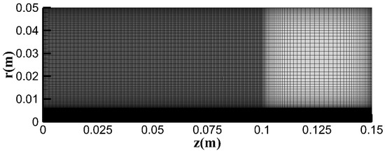
Figure 6.
Non-uniform structured grid.
From Figure 5, it can be seen that the left boundary is the fuel flow and wake air inlet in a radial direction from inside to outside, both of which are set as velocity inlet boundaries. The velocity distribution at the wake air inlet is set as uniform distribution, and the distribution of the fuel flow inlet velocity conforms to the fully developed parabolic distribution [26]. The lower boundary is the axis of symmetry, and the gradient of each physical quantity here is 0. The upper boundary is the free sliding wall. The right boundary is the pressure outlet.
2.3. Fluid Mechanics Model
For all flows involving heat transfer, it is necessary to solve the three basic conservation equations of mass, momentum, and energy:
where z represents the axial coordinate, represents the axial velocity component, r represents the radial coordinate, is the radial velocity component, and is the density of the gas mixture. represents static pressure, is the dynamic viscosity of the gas mixture, and g = 9.8 m/s2 is the gravitational acceleration. represents specific enthalpy, T represents the temperature of the gas mixture, represents the specific constant pressure heat capacity of the mixture, represents the thermal conductivity of the mixture, is the total number of meteorological components, and represents the axial and radial diffusion fluxes of the k-th gas-phase component, respectively, τ represents viscous dissipative stress, and is the energy source term derived from the chemical reaction tropics.
2.4. Radiation Model
The radiation model adopts the discrete coordinate model. It can calculate the scattering medium, considering the directivity of the radiation transfer equation and the influence of boundary emissivity. For the radiation characteristics of gases, the Weighted Sum of Gray Gas (WSGG) model [27] was used for calculation. The WSGG model is an approximate model that combines accuracy and computational efficiency, with higher accuracy than the assumption of complete gray gas, and less computational resource consumption than the line-by-line integration method with the highest accuracy. The core idea is to assume that the spectral absorption coefficient of a gas is composed of several gray gases with absorption coefficients that do not change with wavelength, as well as transparent windows.
The total Emissivity of the gas is expressed as [27]:
where is the sum of the partial pressures of the emission-absorption components, S is the path length, represents the emission weight of the I-th gray gas in the corresponding spectral range, and is the pressure absorption coefficient of the I-th gray gas. The gas radiation in this study only considers the emission of CO2 and H2O, which have the greatest influence on gas radiation heat transfer, and the pressure absorption coefficient can be expressed as [26]:
where and represent the partial pressure of CO2 and H2O, respectively, and and represent the pressure absorption coefficients of CO2 and H2O, respectively.
The weight coefficient determined by temperature can be represented by a polynomial of temperature [27]:
In the formula, is the coefficient of the J-order polynomial of the ith gray gas. For the transparent window, its weight coefficient is the difference between the total weight 1 and the weight coefficient of the rest gray gas [27]:
The conservation of radiation energy is ensured by this calculation method.
The WSGG model coefficients used in the radiation calculation in this study are from a set of coefficients proposed by Dorigon et al. [27] based on HITEMP2010, I = 4, and J = 4.
Due to the high emissivity of soot particles, the radiation heat transfer of soot has a greater impact on temperature than that of gas components. Therefore, the total absorption coefficient includes two parts: gas absorption coefficient and soot absorption coefficient, namely [28]:
In this equation, is the gas absorption coefficient obtained above, and is the soot absorption coefficient, which can be calculated by the following expression [28]:
where and are the model coefficients, is the gas-phase mixture density, and is the soot mass fraction.
2.5. Soot Model
In this study, an improved bipartite model is used to calculate soot generation. This model, first proposed by Leung et al. [29], is a semi-empirical model. The governing equation is the conservation equation of the soot mass fraction and the soot particle number density in the mixture per unit mass [30]:
In the formula, is the density of the gas-phase mixture, u and v represent the velocity components in the z direction (axial) and r direction (radial), respectively, and represent the thermal swimming velocity components of the soot in the axial and radial directions, respectively, which are related to fluid physical properties and temperature gradient, and can be obtained by the following expression [30]:
The formation process of soot includes nucleation, surface growth, coagulation, and oxidation. This model assumes that the nucleation process of soot is only determined by acetylene, i.e., [29]:
Nucleation rate can be expressed as [25]:
where represents the molar concentration of acetylene.
The source term of mass fraction generated by soot nucleation is [30]:
where = 12 g/mol is the molar mass of smoke.
The surface growth process of soot is as follows [29]:
The surface growth rate can be expressed as [26]:
where is the surface area of soot per unit volume, and the calculation method is as follows [30]:
where is the average density of soot particles.
The source term of mass fraction generated by the growth of the soot surface is [30]:
The oxidation process of soot uses the oxidation model proposed by Lee et al. [31]. Considering the oxidation of OH and O2, the source term of its mass fraction is as follows [28]:
In the formula, , , , are all model constants, and are the mass fractions of OH and O2, respectively, and M is the mass concentration of soot per unit volume.
The source term of soot particle number density generated by soot nucleation is [30]:
where is the model constant, is the Boltzmann constant.
At this point, the source terms and in the two equations are calculated by the above process [30]:
3. Results and Discussion
3.1. Verification of the Calculation Model
The temperature field and the volume fraction of soot were compared with the experimental results in literature to verify the accuracy of the model.
Figure 7 shows the calculated radial temperature distribution at z = 20 mm and z = 50 mm from the nozzle axial position. The numerical calculation results were compared with the experimental results of Santoro et al. [32], and different colors were used to distinguish different axial positions. The radial variation trend of temperature is similar to that of the axial velocity component, which increases first and then decreases with the increase in the radial distance. Moreover, with the increase in the axial distance, the peak temperature gradually decreases, and the corresponding radial position gradually approaches the center line. The deviation between the numerical calculation and the experimental results is relatively small. Although the deviation increases in some positions after using the simplified reaction mechanism model, it is still within the acceptable range.
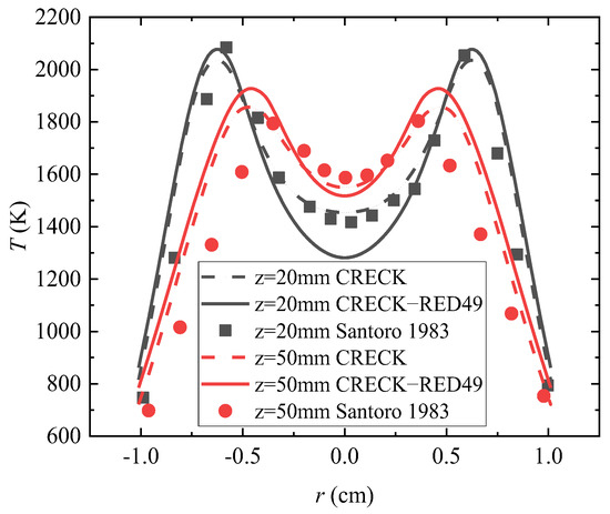
Figure 7.
Comparison of temperature radial distribution values and experimental results [25].
Figure 8 shows the distribution of the radial soot volume fraction from the nozzle axial position z = 20 mm and z = 50 mm obtained through numerical calculation. The numerical calculation results were compared with the experimental results of Santoro et al. [31]. Figure 9 shows the comparison between the axial distribution of integrated soot volume fraction obtained by numerical calculation and the experimental results of Santoro et al. [31]. Integrated soot volume fraction is a representation of the total amount of soot at a specific axial position, which is defined as [32]:
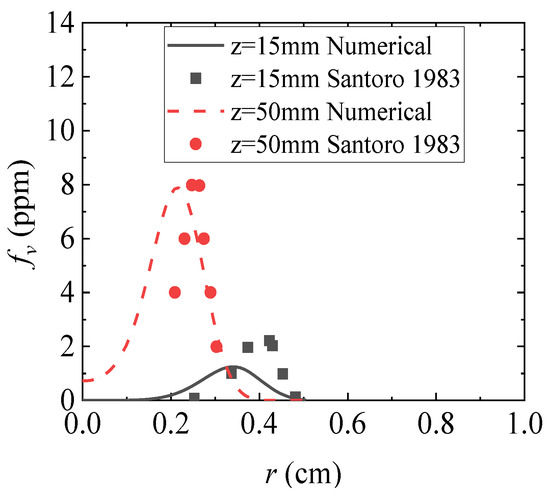
Figure 8.
Radial distribution of soot volume fraction and experimental results [25].
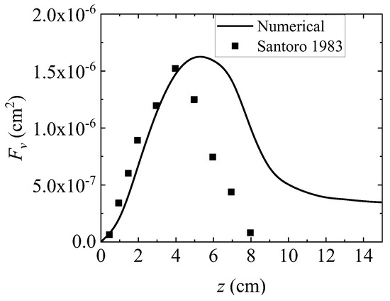
Figure 9.
Axial distribution values and experimental results of integrated black body integral numbers of integrated smoke [25].
It can be seen from Figure 6 and Figure 7 that the soot particles of the flame diffused by the ethylene laminar coaxial jet are mainly concentrated on both sides of the flame. Although the simple model using two-sided equations cannot obtain exactly the same results as the experimental results, it can provide relatively reliable results in qualitative and quantitative analysis.
3.2. Influencing Factors of Soot Generation in Laminar Diffusion Flame of Ethylene
To study the changes in fuel flow and wake air volume flow rate, as well as the influence of gas additives on temperature field and smoke generation, nine different operating conditions were selected in this study. The average inlet velocity and component volume fraction of each operating condition are shown in Table 1. Among them, the parameter settings for condition 1, condition 2, and condition 6 are selected from the experimental condition settings of Santoro et al. [32], representing three typical states of ethylene laminar diffusion flame soot generation, namely no smoke, initial smoke, and smoke state, respectively. Condition 3 further increases the fuel flow volume fraction to the same level as condition 6, based on conditions 1 and 2. Working conditions 4 and 5 change the volume flow rate of the accompanying air based on working condition 1. On the basis of condition 6, conditions 7–8 maintain the volume flow rate of the fuel flow and the accompanying air constant and mix different gas additives with a volume of 10% of the fuel flow in the fuel flow.

Table 1.
Calculation of Soot Generation under Various Operating Parameter Conditions.
Figure 10 shows the cloud map of soot volume fraction obtained by numerical calculation under working conditions 4, 1, and 5.
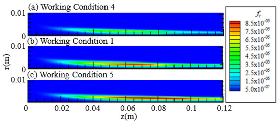
Figure 10.
Soot volume fraction cloud image.
Figure 11 shows the radial distribution of the soot volume fraction obtained through numerical calculation at the axial distance z = 40 mm and z = 70 mm from the burner nozzle under working condition 4 (solid line), working condition 1 (line), and working condition 5 (point line). Different colors are used to distinguish different coaxial positions. Figure 12 shows the axial distribution of the integral soot volume fraction obtained through numerical calculation under working conditions 4, 1, and 5.
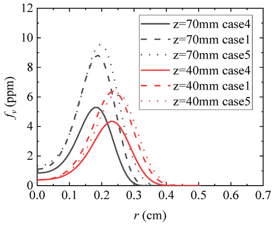
Figure 11.
Radial distribution of smoke black volume fraction.
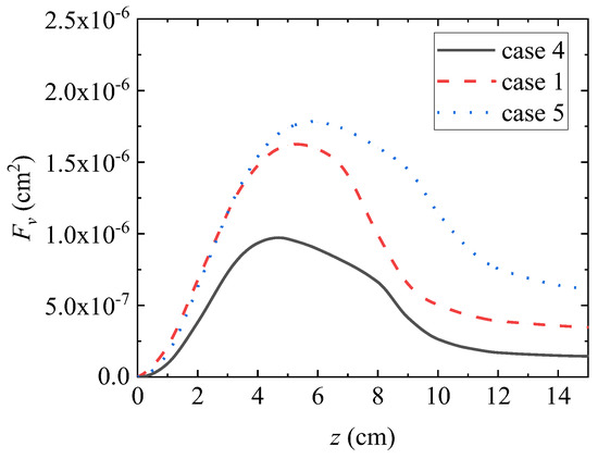
Figure 12.
Axial distribution of integral numbers in black body of integrated smoke.
It can be seen from Figure 10, Figure 11 and Figure 12 that, when compared with the calculation results of operating conditions 4, 1, and 5, the fuel inlet volume flow rate remains unchanged at 3.85 cm3/s, and the soot volume fraction at each axial position is significantly increased by gradually increasing the wake air volume flow rate from 500 cm3/s to 1068.3 cm3/s. Peak integrated soot volume fraction increased by 80%. It can be seen that under the experimental conditions set in this study, the soot emission from the flame of vinyl laminar flow can be increased by increasing the volume flow of wake air. Compared with the calculation results of working condition 1 and 5, it can be seen that as the volume flow rate of wake air continues to increase, the increase in soot volume fraction slows down, and from the perspective of radial distribution, the soot volume fraction increases mainly on the side of wake air.
Figure 13 shows the cloud map of soot volume fraction obtained by numerical calculation under working conditions 3 and 6.
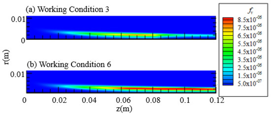
Figure 13.
Cloud image of soot volume fraction.
Figure 14 and Figure 15 show the radial distribution and the axial distribution of the integral soot volume fraction obtained by numerical calculation under working condition 3 (solid line) and working condition 6 (crossed line).
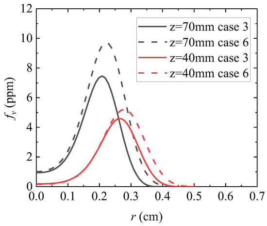
Figure 14.
Radial distribution of soot volume fraction.
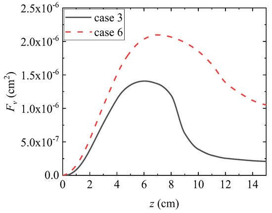
Figure 15.
Axial distribution of integrals in the black body of integrated smoke.
From Figure 13, Figure 14 and Figure 15, it can be seen that keeping the fuel inlet volume flow rate at 4.90 cm3/s results in an improvement when compared to conditions 1, 4, and 5. By increasing the volume flow rate of the accompanying air from 713.3 cm3/s to 1068.3 cm3/s, the volume fraction of soot at each axial position increased. This conclusion is consistent with the comparison results of conditions 1, 4, and 5 with smaller fuel volume flow rates. At the same time, it can be noted that, when compared with the calculation results from condition 1 to condition 5 and from condition 3 to condition 6, due to the increase in fuel volume flow rate, the volume fraction of soot increases more significantly with the increase in wake air volume flow rate.
Figure 16 shows the cloud map of smoke volume fraction obtained through numerical calculation under condition 2. Figure 15 shows the radial distribution of soot volume fraction at the axial distance and position of the burner nozzle obtained from numerical calculations under conditions 1 (solid line), 2 (dashed line), and 3 (dotted line). Different colors are used to distinguish different axial positions. Figure 16 shows the axial distribution of the integrated soot volume fraction obtained through numerical calculation under conditions 1, 2, and 3.

Figure 16.
Cloud Chart of Smoke Black Volume Fraction.
From Figure 10b, Figure 13a, Figure 16, Figure 17 and Figure 18, it can be seen that the inlet volume flow rate of the trailing air remains unchanged at 713.3 cm3/s. As the fuel volume flow rate increases from 3.85 cm3/s to 4.60 cm3/s, the volume fraction of soot increases. However, as the fuel volume flow rate continues to increase to 4.90 cm3/s, the volume fraction of soot decreases overall, and the peak of the integrated volume fraction of soot moves further away from the axial distance of the burner nozzle. As the fuel volume flow rate increases, two different trends of increasing and decreasing soot concentration were observed. This is because the concentration of soot is influenced by processes such as nucleation, surface growth, and oxidation. On the one hand, the increase in fuel volume flow rate leads to an increase in flame length, but the internal temperature of the flame at the same axial position decreases, leading to a decrease in the nucleation and surface growth rate of soot. On the other hand, an increase in flame height will prolong the residence time of soot in the high-temperature zone of the flame and weaken the rate of oxidation. In different situations, the importance of the above two influencing factors is different, so different conclusions will be drawn. From the radial distribution perspective, under the operating conditions set in this study, as the fuel volume flow rate increases, the volume fraction of soot on the fuel flow side decreases, while the volume fraction of soot on the wake air side increases.
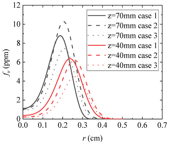
Figure 17.
Radial distribution of smoke black volume fraction.
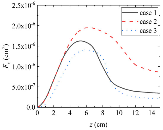
Figure 18.
Axial distribution of integrated soot volume fraction.
Figure 19 and Figure 20 show the radial distribution of smoke volume fraction and the axial distribution of integrated smoke volume fraction obtained from numerical calculations under conditions 5 (solid line) and 6 (dashed line). Keeping the volume flow rate of the accompanying air at 1068.3 cm3/s results in improvement compared to conditions 1, 2, and 3. By increasing the volume flow rate of the fuel flow from 3.85 cm3/s to 4.90 cm3/s, the volume fraction of soot decreases on the fuel flow side and slightly increases on the accompanying air side at relatively low axial distances from the burner nozzle. The variation pattern obtained from the calculation results of conditions 1, 2, and 3 with smaller volume flow of accompanying air is consistent. At higher axial positions, the integral soot volume fraction increases with the increase in fuel volume flow rate, which is consistent with the variation law obtained from the calculation results of working conditions 1 and 2. From this, it can be seen that when the volume flow rate of the accompanying air is sufficient, the volume fraction of soot in each axial position will significantly increase with an increase in fuel volume flow rate. However, when the fuel volume flow rate increases to a certain amount, if the volume flow rate of the accompanying air is not correspondingly increased, the overall volume fraction of soot will show a downward trend, even less than the volume fraction of soot under the fuel volume flow condition before increasing.
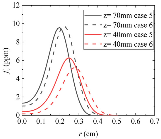
Figure 19.
Radial distribution of soot volume fraction.
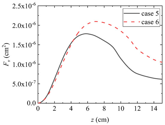
Figure 20.
Axial distribution of integrated soot volume fraction.
Figure 21 shows the cloud map of smoke volume fraction obtained through numerical calculation under conditions 7, 8, and 9. Figure 22 shows the radial distribution of smoke volume fraction at the axial positions z = 40 mm and z = 70 mm, respectively, calculated under conditions 6 (solid line), 7 (dashed line), 8 (dotted line), and 9 (dotted line). Different colors are used to distinguish different axial positions. Figure 23 shows the axial distribution of the integrated soot volume fraction obtained through numerical calculation under conditions 6, 7, 8, and 9.
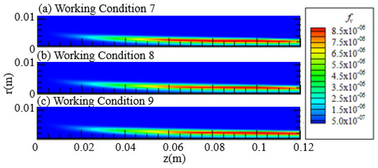
Figure 21.
Cloud Chart of Soot Volume Fraction.
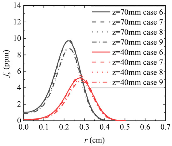
Figure 22.
Radial distribution of soot volume fraction.
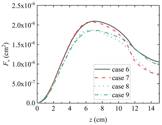
Figure 23.
Axial distribution of integral numbers in black body of integrated smoke.
From Figure 21, Figure 22 and Figure 23, it can be seen that while maintaining a constant volume flow rate of fuel C2H4 and the accompanying air, various gas additives with a volume fraction of 10% of the fuel flow can be added to the fuel flow to suppress the generation of soot. Gas additives typically suppress the generation of soot through a combination of thermal, dilution, and chemical effects [33]. Due to the fact that the dual equation semi-empirical model used in this study cannot directly involve gas additives in the chemical reaction processes of soot precursors, nucleation, surface growth, etc., the calculation results in this study only obtain the inhibitory effect of gas additives on soot from the perspectives of thermal effect, dilution effect, and chemical response to a single precursor C2H2. Under the above limiting conditions, different gas additives with the same volume flow rate were added to conditions 7, 8, and 9. The addition of H2 reduced the integrated smoke volume fraction at the higher axial position, CO2 reduced the integrated smoke volume fraction at the lower axial position, and H2O reduced the integrated smoke volume fraction throughout the entire calculation domain.
4. Conclusions
To establish a calculation model for the volume distribution of soot in ethylene laminar coaxial jet diffusion flames, researchers explore the changes in fuel flow and wake air volume flow rate, as well as the influence of gas additives on temperature field and soot generation. This study simplifies the detailed chemical reaction mechanism model and improves the soot model by establishing a numerical calculation model that can describe the velocity field, temperature field, component concentration field, and soot volume fraction distribution of ethylene laminar coaxial jet diffusion flame and verify its accuracy. The factors affecting the generation of soot were investigated by changing the inlet volume flow rate and fuel flow composition. The following is the conclusion:
- (1)
- In terms of mechanism simplification, the detailed chemical reaction mechanism model, CRECK model, was simplified according to the demand for the accuracy of specific physical quantities in the follow-up study and the demand for saving computing resources. A simplified model, CRECK-RED49, consisting of 49 components and 640 elementary reactions was obtained, and the calculation accuracy was verified to meet the accuracy requirements for soot generation calculation.
- (2)
- For the improvement of soot model, a two-path soot solver was developed to calculate the soot volume concentration distribution in the laminar coaxial jet diffusion flame of ethylene. The calculated results obtained are consistent with the experimental data in terms of distribution trend. The deviation of the calculated peak integral smoke volume fraction is only 5%.
- (3)
- Concentration of soot is influenced by processes such as nucleation, surface growth, and oxidation. When the volume flow rate of the ac-companying air is sufficient, the volume fraction of soot in each axial position will first increase and then decrease with the increase of fuel volume flow rate. When the fuel volume flow rate reaches 4.60 cm3/s, the volume fraction of soot reaches its peak.
- (4)
- In terms of the influence of gas additives on the formation of soot, the addition of H2, CO2, and H2O in the fuel flow can suppress the formation of soot in ethylene laminar diffusion flames. From the perspective of thermal effect, dilution effect, and chemical effect on a single precursor C2H2, the addition of H2O has the most significant inhibitory effect on soot formation.
The soot calculation solver developed in this study is universal and scalable for the calculation of soot generation under engineering application conditions and reduces the consumption of computational resources compared to models that consider the detailed reaction mechanism of soot. It is of great significance for achieving rapid modeling of soot generation in flames.
Author Contributions
X.-Y.G.: Conceptualization, Methodology, Software, Writing—Original draft. F.Y.: Writing—review and editing, Visualization, Formal analysis. C.-X.Z.: Data Curation. Q.-X.C.: Project administration. Y.Y.: Supervision. All authors have read and agreed to the published version of the manuscript.
Funding
This study was supported by the China Postdoctoral Science Foundation (No. 2022M720943), Qi-Xiang Chen.
Institutional Review Board Statement
Not applicable.
Informed Consent Statement
Not applicable.
Data Availability Statement
For the raw air quality data, meteorological data, and AOD data files, please contact yuanyuan83@hit.edu.cn.
Acknowledgments
This study was supported by the China Postdoctoral Science Foundation (No. 2022M720943). A very special acknowledgement is made to the editors and referees who provided important comments that improved this study.
Conflicts of Interest
The authors declare no conflict of interest.
References
- Bond, T.C.; Doherty, S.J.; Fahey, D.W.; Forster, P.M.; Berntsen, T.; DeAngelo, B.J.; Flanner, M.G.; Ghan, S.; Kärcher, B.; Koch, D.; et al. Bounding the role of black carbon in the climate system: A scientific assessment. J. Geophys. Res. Atmos. 2013, 118, 5380–5552. [Google Scholar]
- Zheng, S.; Zhang, Y.; Yang, Y.; Lu, Q. Blending Effects of Nitrogenous Bio-Fuel on Soot and NOX Formation during Gasoline Combustion. Energy Fuels 2023, 37, 4596–4607. [Google Scholar]
- Ying, Y.; Liu, D. Effects of n-Butanol Addition on the Combustion Characteristics of n-Heptane Counterflow Diffusion Flame at Elevated Pressure. Fire 2022, 5, 154. [Google Scholar] [CrossRef]
- Zhu, X.; Liu, B.; Guo, C.; Li, Z.; Cheng, M.; Zhu, X.; Wei, Y. Short and long-term association of exposure to ambient black carbon with all-cause and cause-specific mortality: A systematic review and meta-analysis. Environ. Pollut. 2023, 324, 121086. [Google Scholar] [CrossRef] [PubMed]
- Jerez, A.; Consalvi, J.-L.; Fuentes, A.; Liu, F.; Demarco, R. Soot production modeling in a laminar coflow ethylene diffusion flame at different Oxygen Indices using a PAH-based sectional model. Fuel 2018, 231, 404–416. [Google Scholar] [CrossRef]
- Wang, Y.; Liu, X.; Gao, Y.; Gu, M.; An, X. Numerical simulations on effects of oxygen concentration on the structure and soot formation in a two-dimensional axisymmetric laminar C2H4/(O-2-CO2) diffusion flame. J. Therm. Anal. Calorim. 2019, 137, 689–702. [Google Scholar]
- Eaves, N.A.; Zhang, Q.; Liu, F.; Guo, H.; Dworkin, S.B.; Thomson, M.J. CoFlame: A refined and validated numerical algorithm for modeling sooting laminar coflow diffusion flames. Comput. Phys. Commun. 2016, 207, 464–477. [Google Scholar]
- Zheng, S.; Yang, Y.; Sui, R.; Lu, Q. Effects of C2H2 and C2H4 radiation on soot formation in ethylene/air diffusion flames. Appl. Therm. Eng. 2021, 183, 116194. [Google Scholar]
- Jerez, A.; Villanueva, J.C.; da Silva, L.F.; Demarco, R.; Fuentes, A. Measurements and modeling of PAH soot precursors in coflow ethylene/air laminar diffusion flames. Fuel 2019, 236, 452–460. [Google Scholar] [CrossRef]
- Zimmer, L.; Kostic, S.; Dworkin, S.B. A novel soot concentration field estimator applied to sooting ethylene/air laminar flames. Eng. Appl. Comput. Fluid Mech. 2019, 13, 470–481. [Google Scholar] [CrossRef]
- Zimmer, L.; Pereira, F. Limitations of simplified models to predict soot formation in laminar fames. J. Braz. Soc. Mech. Sci. Eng. 2020, 42, 340. [Google Scholar] [CrossRef]
- Cepeda, F.; Jerez, A.; Demarco, R.; Liu, F.; Fuentes, A. Influence of water-vapor in oxidizer stream on the sooting behavior for laminar coflow ethylene diffusion flames. Combust. Flame 2019, 210, 114–125. [Google Scholar] [CrossRef]
- Wang, Y.; Liu, X.; Gu, M.; An, X. Numerical simulation of the effects of hydrogen addition to fuel on the structure and soot formation of a laminar axisymmetric coflow C2H4/(O-2-CO2) diffusion flame. Combust. Sci. Technol. 2019, 191, 1743–1768. [Google Scholar] [CrossRef]
- Liu, F.; Guo, H.; Smallwood, G.J. Evaluation of the laminar diffusion flamelet model in the calculation of an axisymmetric coflow laminar ethylene–air diffusion flame. Combust. Flame 2006, 144, 605–618. [Google Scholar] [CrossRef]
- Qiu, L.; Hua, Y.; Zhuang, Y.; Wei, J.; Qian, Y.; Cheng, X. Numerical investigation into the decoupling effects of hydrogen blending on flame structure and soot formation in a laminar ethylene diffusion flame. Int. J. Hydrogen Energy 2020, 45, 15672–15682. [Google Scholar] [CrossRef]
- Yang, Y.; Zheng, S.; He, Y.; Liu, H.; Sui, R.; Lu, Q. Effects of simultaneous CO2 addition to the fuel and oxidizer streams on soot formation in co-flow diffusion ethylene flame. Fuel 2023, 353, 129181. [Google Scholar] [CrossRef]
- Yang, Y.; Zheng, S.; Sui, R.; Lu, Q. Impact of ammonia addition on soot and NO/N2O formation in methane/air co-flow diffusion flames. Combust. Flame 2023, 247, 112483. [Google Scholar] [CrossRef]
- Ranzi, E.; Frassoldati, A.; Grana, R.; Cuoci, A.; Faravelli, T.; Kelley, A.P.; Law, C.K. Hierarchical and comparative kinetic modeling of laminar flame speeds of hydrocarbon and oxygenated fuels. Prog. Energy Combust. Sci. 2012, 38, 468–501. [Google Scholar] [CrossRef]
- Wang, W.; Gou, X. A mechanism reduction method integrating path flux analysis with multi generations and sensitivity analysis. Combust. Sci. Technol. 2017, 189, 24–42. [Google Scholar] [CrossRef]
- Lu, T.F.; Law, C.K. A directed relation graph method for mechanism reduction. Proc. Combust. Inst. 2005, 30, 1333–1341. [Google Scholar] [CrossRef]
- Nurislamova, L.F.; Gubaydullin, I.M. Mechanism reduction of chemical reaction based on sensitivity analysis: Development and testing of some new procedure. J. Math. Chem. 2017, 55, 1779–1792. [Google Scholar] [CrossRef]
- Kopp, M.M.; Donato, N.S.; Petersen, E.L.; Metcalfe, W.K.; Burke, S.M.; Curran, H.J. Oxidation of ethylene–air mixtures at elevated pressures, Part 1: Experimental results. J. Propuls. Power 2014, 30, 790–798. [Google Scholar] [CrossRef]
- Van Treek, L.; Roth, N.; Seidel, L.; Mauß, F. Measurements of the laminar burning velocities of rich ethylene/air mixtures. Fuel 2020, 275, 117938. [Google Scholar] [CrossRef]
- Le Cong, T.; Bedjanian, E.; Dagaut, P. Oxidation of ethylene and propene in the presence of CO2 and H2O: Experimental and detailed kinetic modeling study. Combust. Sci. Technol. 2010, 182, 333–349. [Google Scholar] [CrossRef]
- Santoro, R.J.; Semerjian, H.G.; Dobbins, R.A. Soot particle measurements in diffusion flames. Combust. Flame 1983, 51, 203–218. [Google Scholar] [CrossRef]
- Sert, İ.O.; Sezer-Uzol, N. Numerical analysis of convective heat transfer of nanofluids in circular ducts with two-phase mixture model approach. Heat Mass Transf. 2016, 52, 1841–1850. [Google Scholar] [CrossRef]
- Dorigon, L.J.; Duciak, G.; Brittes, R.; Cassol, F.; Galarça, M.; França, F.H. WSGG correlations based on HITEMP2010 for computation of thermal radiation in non-isothermal, non-homogeneous H2O/CO2 mixtures. Int. J. Heat Mass Transf. 2013, 64, 863–873. [Google Scholar] [CrossRef]
- ANSYS, I. Fluent Theroy Guide [EB/OL]. Available online: https://ansyshelp.ansys.com/account/secured?returnurl=/Views/Secured/corp/v211/en/flu_th/flu_th.html (accessed on 9 February 2023).
- Leung, K.M.; Lindstedt, R.P.; Jones, W.P. A simplified reaction-mechanism for soot formation in nonpremixed flames. Combust. Flame 1991, 87, 289–305. [Google Scholar] [CrossRef]
- Liu, F.; Guo, H.; Smallwood, G.J.; Gülder, Ö.L. Numerical modelling of soot formation and oxidation in laminar coflow non-smokifig and smoking ethylene diffusion flames. Combust. Theory Model. 2003, 7, 301–315. [Google Scholar] [CrossRef]
- Lee, K.B.; Thring, M.W.; Beer, J.M. On the rate of combustion of soot in a laminar soot flame. Combust. Flame 1962, 6, 137–145. [Google Scholar] [CrossRef]
- Santoro, R.J.; Yeh, T.T.; Horvath, J.J.; Semerjian, H.G. The transport and growth of soot particles in laminar diffusion flames. Combust. Sci. Technol. 1987, 53, 89–115. [Google Scholar] [CrossRef]
- Gu, M.; Chu, H.; Liu, F. Effects of simultaneous hydrogen enrichment and carbon dioxide dilution of fuel on soot formation in an axisymmetric coflow laminar ethylene/air diffusion flame. Combust. Flame 2016, 166, 216–228. [Google Scholar] [CrossRef]
Disclaimer/Publisher’s Note: The statements, opinions and data contained in all publications are solely those of the individual author(s) and contributor(s) and not of MDPI and/or the editor(s). MDPI and/or the editor(s) disclaim responsibility for any injury to people or property resulting from any ideas, methods, instructions or products referred to in the content. |
© 2023 by the authors. Licensee MDPI, Basel, Switzerland. This article is an open access article distributed under the terms and conditions of the Creative Commons Attribution (CC BY) license (https://creativecommons.org/licenses/by/4.0/).