Review

A Review of Combustion and Flame Spread over Thermoplastic Materials: Research Advances and Prospects

1
Department of Fire Protection Engineering, Southwest Jiaotong University, Chengdu 610031, China
2
State Key Laboratory of Fire Science, University of Science and Technology of China, Hefei 230027, China
*
Author to whom correspondence should be addressed.
Fire 2023, 6(3), 125; https://doi.org/10.3390/fire6030125
Submission received: 11 February 2023 / Revised: 6 March 2023 / Accepted: 15 March 2023 / Published: 17 March 2023
(This article belongs to the Special Issue Building Fire Dynamics and Fire Evacuation)

Abstract

:
As thermoplastic materials are widely used in buildings, the fire hazards of thermoplastic materials are increasingly becoming a central issue in fire safety research due to their unique pyrolysis and melting mechanisms. In this paper, the features and common types of thermoplastic materials are introduced first. Then, the combustion behavior of thermoplastic materials is theoretically analyzed based on the empirical formulas and heat balance equations, such as the pyrolysis kinetics, ignition time, melting and dripping, flame, burning rate and mass loss rate, temperature and heat flow, gas products, and influencing factors. The influencing factors basically include the sample properties (width, incline angle, and thickness, etc.), the façade structure (sidewalls, curtain wall, etc.), the ambient conditions (altitude, pressure, and gravity, etc.), and the flame retardant treatment. Similarly, this study also illustrates the vertical and horizontal flame spread behavior of the thermoplastic materials and the influencing factors. The utilized methods include the experimental methods, the analytical methodologies, and the approaches for numerical simulation. Finally, the problems encountered at this stage and worthy of further study in the future are presented.

1. Introduction

Due to the growth of material science, thermoplastic materials have been widely used in furniture, interior decoration, and building insulation, etc., but they can melt, drip, and flow when heated, forming wall flames or oil pool flames, which can speed up the spread of flames, expand the flame area, generate toxic gases, and greatly increase the fire hazard. The flame spread process of thermoplastic materials is extremely complex and is not only related to the pyrolysis mechanism and ignition characteristics of the material but also closely related to the ambient conditions, including ambient temperature, heat radiation intensity, and smoke gases. In recent years, current domestic and international studies have investigated the combustion and flame spread law of thermoplastic materials under the coupling of ambient pressure [1,2,3,4,5,6,7,8,9], oxygen concentration [10,11,12], radiation intensity [13,14,15], sample properties [16,17,18,19,20,21,22], and façade structures [23,24,25,26,27,28,29,30,31,32,33,34], mainly on several typical thermoplastic materials, such as PMMA (polymethylmethacrylate), PS (polystyrene), and PU (polyurethane).
Lots of combustion parameters are important in the study of the combustion of thermoplastic materials, such as pyrolysis rate, ignition time, melting times, dripping frequency, flame shape and geometry, flame temperature, heat flow, and the concentration of gas products, etc. The kinetic decomposition of thermoplastic materials provides insight into the reaction process and predicts the rate of the reaction. Previous approaches to the kinetics of thermal decomposition include the model-free method, the model-fitting method, and the distributed activation energy model (DAEM)-fitting method; some scholars have also proposed their own models [35,36,37,38,39,40,41,42,43,44,45,46]. The classical ignition theory was proposed by Lawson and Sims in 1950, which first revealed the ignition mechanism of solid combustible materials [47]. According to the classical ignition theory, ignition occurred merely when the exterior temperature reached the critical ignition temperature; the gas-phase progress was ignored [48,49,50,51,52,53]. Subsequently, Bal [54] found that the classical ignition theory would fail to predict the ignition at high heat fluxes, which meant the critical temperature changed with incident heat flux [55]. Based on these fundamental studies, critical mass flux [56,57], observation of flame kernel on the fuel surface [58,59], combustion traces [10], and critical temperature [57,60] were taken as the ignition criteria. Moreover, the researchers also investigated the effect of the parameters such as sample properties [60], step height [61] and location [18], altitude, and pressure [62] on the ignition time.
The combustion behavior of thermoplastic materials is much more complex than that of ordinary materials. It undergoes processes such as melt, pyrolysis, and vaporization when heated, and forms a flowing liquid, resulting in the simultaneous existence and interaction of two modes of combustion: wall flame and pool flame. These melt-flow characteristics increase the fire hazard and may also slow down the flame spread process by moving the combustible materials load from the surface. As shown in Figure 1, the XPS foam surface downward combustion may really be seen as a little pool flame perched on the solid foam. As the flame front descends, the neighboring solid fuel would melt, adding more liquid fuel to the pool [63].
The flame shape of thermoplastic materials can be considerably influenced by the sample’s geometrical characteristics [64], the ambient wind [65,66], and the magnetic field [67]. The main flame parameters that have been previously studied were flame geometry [68,69,70,71,72,73] and flame height and thickness [74,75,76,77,78,79,80,81,82,83,84,85,86]. Most prediction models for flame height are based on the empirical flame height correlations as shown in Equation (1):
  x f = K Q ˙ n
Moreover, the previous studies also investigated the effect of the parameters such as the sample width [81] and inclined angle [72], altitude, pressure, and microgravity [86,87] on flame height.
In combustion experiments of thermoplastic materials, temperature and heat flow are often measured. Laser holographic interferometry and infrared thermography are commonly used measurement methods. Juste et al. [88,89] put forward a new temperature extraction method that combined the laser Mohr deflection method and the two-dimensional Fourier transform method (TFTM), which was approved with good applicability. The study of temperature distribution allowed a better understanding of combustion characteristics. Various gaseous products were produced in various combustion and pyrolysis experiments; the composition and content of these gas products can be used to determine the amount of combustion [90,91].
The flame spread over the thermoplastic materials was caused by a series of physical and chemical changes together. The flame spread contained the natural flame spread, concurrent-flow flame spread, and opposed-flow flame spread. So, a small flame was seen as a finger for both flaming and smoldering combustion. The Lewis number was used as the governing parameter of the finger flame, the expression was as follows [92]:
Le = α ¯ D
Kuwana [93,94,95] revised the effective Lewis number [92]:
Le eff , mod = Le 2 β ( lnU 1 + k U 2 )
These studies have promoted further development of the flame spread theoretical system. Since the opposed-flow flame spread over thermoplastic materials can be quickly stabilized, which is more favorable for experimental operations and heat and mass transfer analysis, a lot of related studies have been conducted on this type of flame spread. However, the concurrent-flow flame spread of thermoplastic materials has been little studied due to the instability of the flame spread process. The main influencing factors in previous studies on the flame spread are as follows: sample properties (width, angle, and thickness) [96,97,98], ceiling properties [99], and ambient conditions [100] (altitude, ambient pressure, microgravity). For the flame spread over thermoplastic material surfaces, the concurrent-flow flame spread is faster compared to the opposed-flow flame spread because the high temperature smoke would flow through the unburnt portion and the unburnt portion would receive more heat from the flame and the hot smoke. Whether these physical models can be applied to different materials depends on the material’s thermal and chemical kinetic characteristics. The sample thickness affects the simplified models and mechanisms of flame spread in thermoplastic materials (plate or cylinder). The primary sample properties (width, angle, thickness, etc.), façade construction, and environmental factors that affected earlier investigations of vertical flame propagation are also discussed.
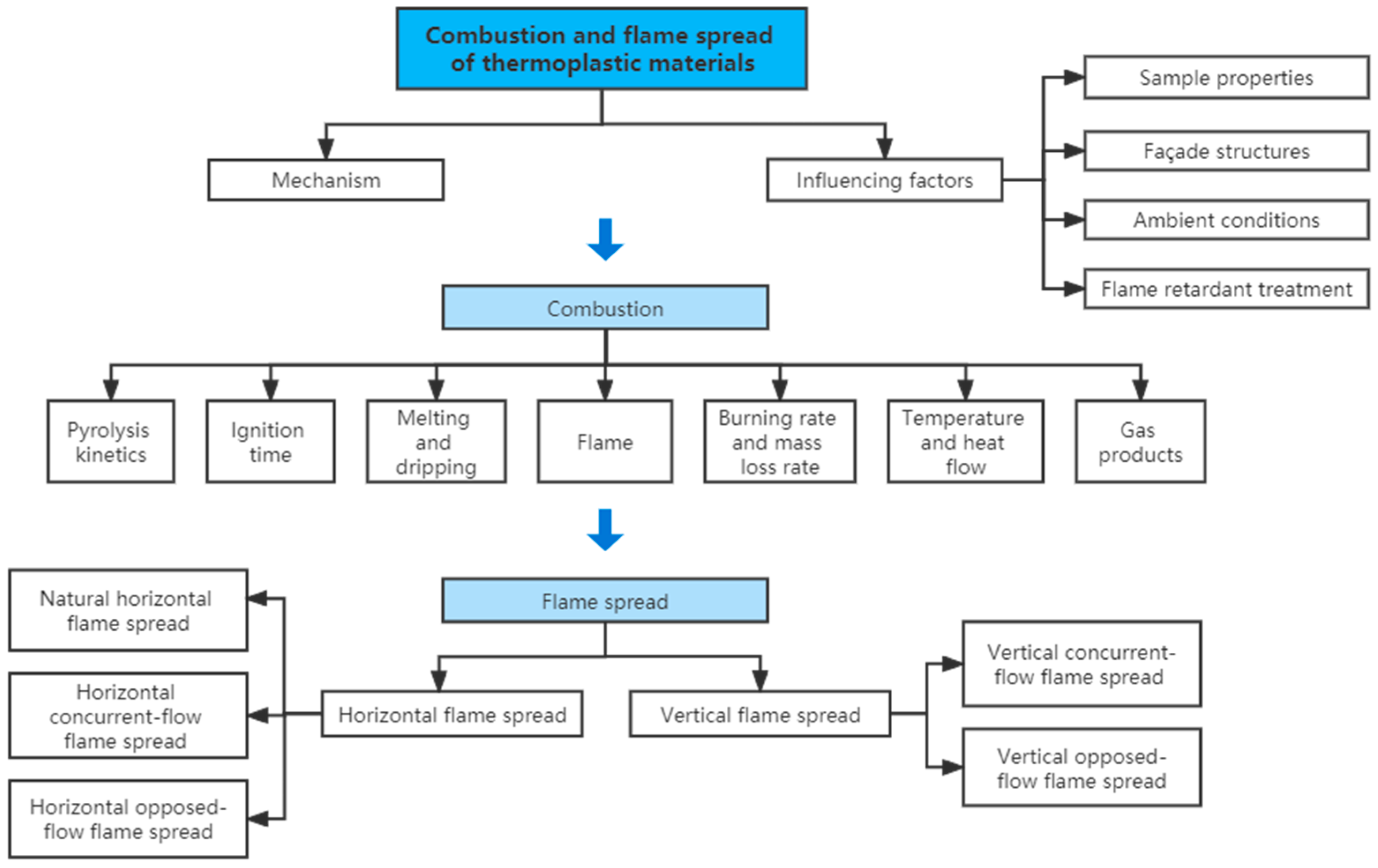
This review discusses the combustion behavior and flame spread process of thermoplastic materials. The kinetics mechanisms and their development are revealed through the pyrolysis, the ignition, the melting and dripping, the flame, the burning rate and mass loss rate, the temperature and heat flow, the gas products, and the flame spread rate of the thermoplastic materials. In these processes, the influencing factors on the thermodynamic parameters of thermoplastic material properties are also illustrated in detail, for example, sample properties, façade structures, ambient conditions, and flame retardant treatment. The content of this study is shown in Figure 2.

2. Thermoplastic Materials

2.1. Thermoplastic Materials and Common Types

The term “thermoplasticity” describes a substance’s capacity to flow and deform when heated and to hold onto a certain shape after cooling. The majority of thermoplastic linear polymers may be easily molded by extrusion, injection, or blow molding. Linear or branched polymers can soften and harden repeatedly by heating and cooling within a certain temperature range.
Thermoplastic materials are possible to classify into general plastics, engineering plastics, special plastics, etc., based on their functional properties, range of applications, and ease of forming technology. The widespread application, simple production, and excellent all-around performance of common plastics are their primary attributes. Polyethylene (PE), polypropylene (PP), polyvinyl chloride (PVC), polystyrene (PS), and acrylonitrile butadiene styrene (ABS) are famous as the “five general plastics”. The characteristics of engineering plastics and special plastics are: some structure and performance of polymers are particularly outstanding, or the molding processing technology is more difficult, often used in professional engineering or special fields and occasions. The main engineering plastics are polyamide, polycarbonate (PC), polyurethane (PU), polytetrafluoroethylene (PTFE), polyethylene terephthalate (PET), etc., and special plastics, such as the “medical polymer” class of “synthetic heart valve”, “artificial joint”, etc.
The main thermoplastic materials covered in this review are PMMA (polymethyl methacrylate), XPS (extruded polystyrene), and EPS (expanded polystyrene). PMMA is a kind of polymer, also known as acrylic or organic glass, which has many advantages, such as high transparency, lightweight, low price, easy mechanical processing, etc. PMMA is frequently used as a material to replace glass. There are two types of polystyrene foam: expanded EPS and continuous extruded XPS. That is, both extruded and polystyrene panels are produced with polystyrene resin as raw material. XPS board is a kind of foaming material that is made by extruding polystyrene, a foaming agent, and a catalyst through an extruder for continuous extrusion and foaming. Polystyrene board, also known as EPS board, benzene board, foam board, and extruded polystyrene foam board, is a polystyrene product made by adding a low boiling point liquid blowing agent to polystyrene beads, and then pre-foaming, maturing, molding, drying, and cutting. Compared with EPS, XPS has low thermal conductivity, high heat resistance, low linearity, and low expansion coefficient.

2.2. Thermal Characteristics of Thermoplastic Materials

Thermoplastic material has the thermal characteristics of room temperature preservation, melting, flammability, and remolding.
Ambient temperature preservation: Thermoplastic materials can be maintained at ambient temperatures without a degradation of performance because thermoplastic composites do not need to worry about chemical reactions. This eliminates the need for refrigerated shipping and refrigeration, which often complicates the logistics of thermoset composites. More complex parts can also be used since there is no timeout to consider.
Melting: Melting is a process in which the kinetic energy of the thermal motion of molecules rises as the temperature rises, resulting in the destruction of crystallization and the transition of the substance from the crystalline to the liquid phase. Simultaneously, the liquid phase mobility improves and the liquid generated by the melt separates from the solid and produces molten droplets that fall due to gravity. In a flame, leaking fuel will create high-temperature combustible material disconnected from the initial place, resulting in additional flames on the scene and inducing thermal danger to nearby persons and properties. Thus, this kind of combustion parameter is of vital value to be researched.
Flammability: Flammability is the ability to burn with flame under specified test conditions. It includes the characteristics related to igniting and the ability to sustain combustion.
Remolding: Because thermoplastic resins may be repeatedly heated and cooled without degrading the performance, thermoplastic materials can be remolded and treated. Broken-down used components can be utilized as feedstock for other procedures, such as compression molding or injection molding.

3. Combustion of Thermoplastic Materials

Thermoplastic material flame hazards have four aspects: first, thermoplastic materials increase the flame load of the building; second, thermoplastic materials will also form a flow of liquid, expanding the scope of the flame; third, the thermoplastic material combustion accelerates the time of the flame to flashover; fourth, burning thermoplastic materials can release a lot of harmful fumes and pollutants into the air.

3.1. Pyrolysis Kinetics

The kinetic decomposition can provide insight into the reaction process and mechanism of pyrolysis as well as the reaction rate. Previous studies on pyrolysis kinetics have been analyzed using the model-free [39,40], model-fitting [39,40], and distributed activation energy model (DAEM) [40,45] methods, and a few proposed their own models [46].
The activation energy could be calculated using the model-free approach [35] when the chemical mechanism is not clear. Commonly used methods were the Friedman (FR) method and the Integration method. Friedman [36] proposed the differential method, which can be expressed as Equation (4):
ln [ β i ( d α dT ) α , i ] = ln [ A α f ( α ) i ] E a RT α , i
Integral methods can also be used to describe the activation energy, such as Flynn–Wall–Ozawa method [37,38]. The Ozawa equation was expressed as Equation (5):
log β = log ( AE a RG ( α ) ) 2.315 0.4567 E a RT
The model-fitting approach was based on the model-free analysis, assuming a primary reaction and using simple mathematical fitting methods to obtain the key kinetic parameters of reactions. There were many model fitting methods, of which Coats and Redfern were the most commonly used methods [41,42]. The most appropriate model for the pyrolysis mechanism was determined based on the optimal kinetic parameters.
Activation energy distribution was first discussed by Vand [43], and then Pitt [44] further improved the approach. The DAEM approach was proposed based on Equation (6):
α = 1 0 exp [ T 0 T A β exp ( E RT ) dT ] f ( E ) dE
where f(E) represented the activation energy distribution. Li et al. [45] used DAEM to reflect the pyrolysis process of several common polymers. The most effective model was chosen based on the comparison of pertinent parameters in other models.
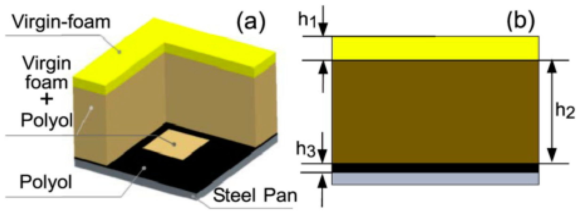
In the study of FPUF combustion with larger dimensions, Liu [46] proposed a new model to depict the pyrolysis in combustion, which was schematically shown in Figure 3. The findings demonstrated that the numerical simulations which employed a model performed better in simulating FPUF combustion under favorable ventilation circumstances.
In addition, the flame retardant treatment would also affect the pyrolysis kinetics. For example, Korobeinichev [101] looked into how the PMMA decomposition rate varied with temperature and heating rates. Adding flame retardant to materials had an effect on the pyrolysis reaction. It was discovered that the composite formed by adding UiO-66 to PMMA had a greater apparent activation energy than pure PMMA, indicating that the mixture had better thermal stability. Stoliarov [102] examined PS and two mixtures of polystyrene with brominated polystyrene (PSBr), and found that the parameters related to the pyrolysis kinetic were significantly affected by the flame retardant additives.

3.2. Ignition Time

The time interval between a flashover on the surface and a persistent flame is referred to as the transitory process of ignition. The ignition time is one way to assess the flammability of a substance. Gas-phase chemistry has a considerable impact on auto-ignition. Since the typical process of auto-ignition differs from that of piloted ignition, judgments concerning piloted ignition cannot always be drawn only based on auto-ignition data.

3.2.1. Mechanism Analysis of Ignition

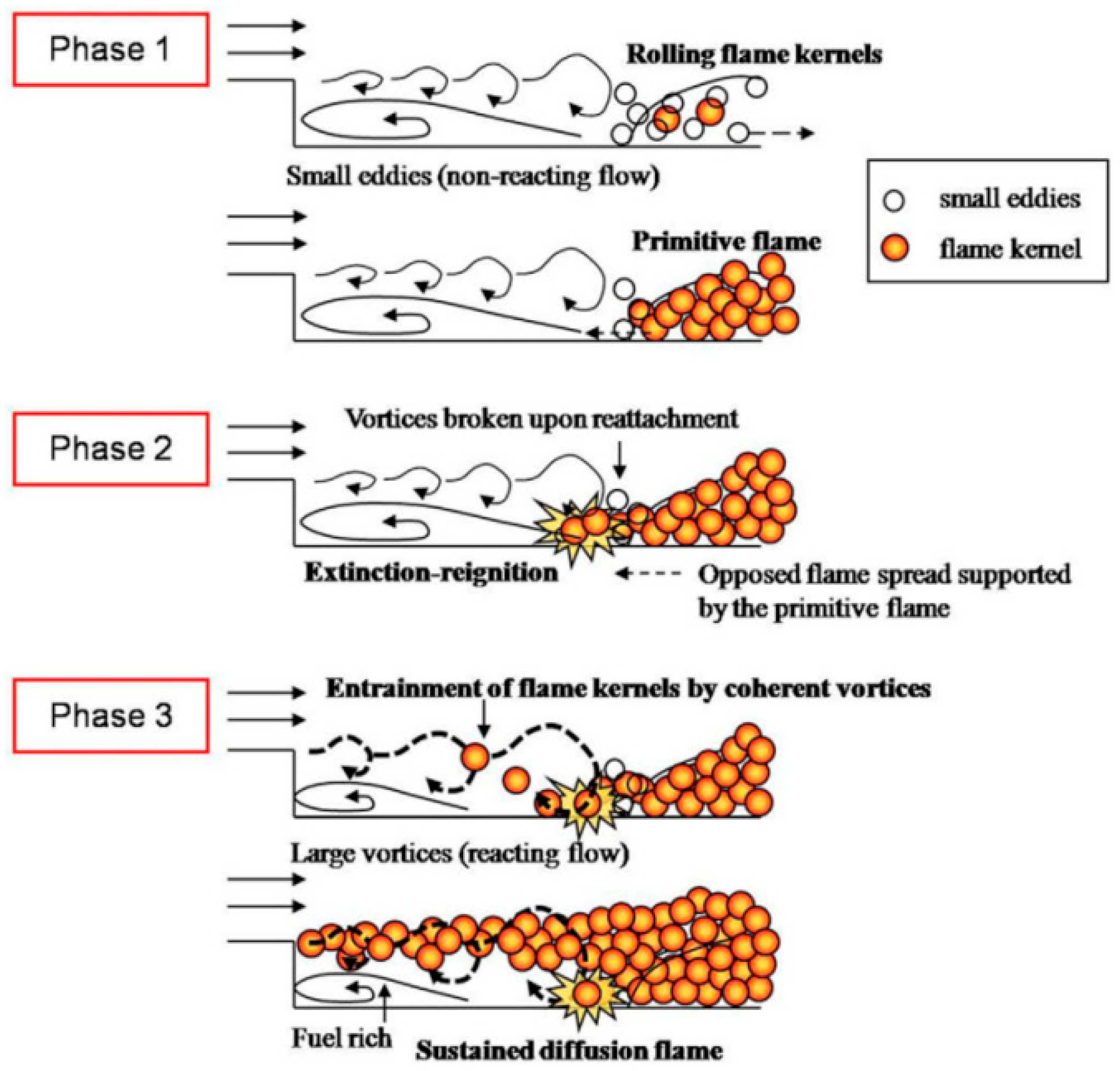
The pre-ignition and post-ignition states demonstrated the dominant position of small and large vortices, respectively, demonstrating the change from small to large vortices because of the heat release [59] as shown in Figure 4. The first ignition was visible towards the downstream of the fuel due to the lowered typical response time and greater mixing, and then a flame formed and made flame spread in the opposite direction.
Previous studies usually used critical mass flux [56,57], critical temperature [57,60], surface combustion traces [10], and the observation of flames on the sample surface [58,59] as the ignition criteria.
Of the above, critical mass flux [56,57] and critical temperature [57,60] were widely used in mechanistic studies. By including a critical mass flow in the analytical model, the thermal degradation process could be incorporated, and a formula to predict the value of ignition time could be derived. As a result, the bulk of past theoretical models was built on this criterion. Bal [54] explained the reason why classical ignition theory fails when heat flux was high and quantified the effect of black-carbon coating, obtaining a predictive model as followed.
m ˙ " = y = 0 y = L A exp ( - E R T ( y , t ) ) w n d y
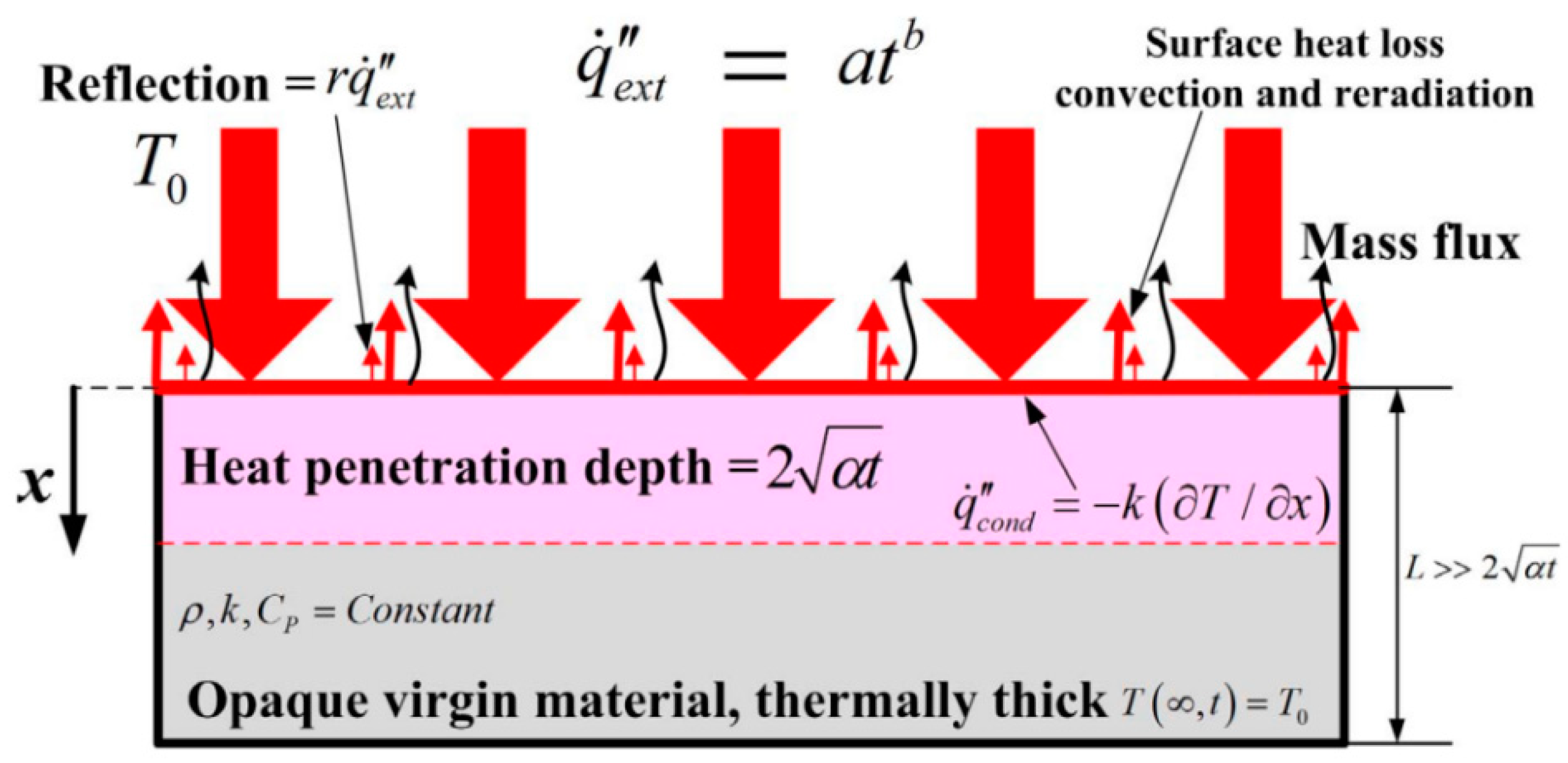
Both linear and quadratic heat fluxes had been studied by Gong who introduced the thermal degradation process in Lautenberger’s [55] study in 2018 [56] and 2019 [57].
Sample heat transfer progress under rising heat flux was shown in Figure 5. Several important assumptions and strategies in Gong’s study were shown as follows:
(1) Only surface absorption was considered, and deep absorption was ignored.
(2) The thermally thick environment was considered. The penetration depth of surface absorption can be approximated as α t [55].
(3) Convective and radiant heat losses were neglected.
(4) The other temperature factors before ignition and the thermal breakdown reaction within the material are disregarded and kept constant.
(5) Replacing the simplified approximate expression with the analysis (accurate) temperature distribution.
(6) Substituting the first-order Arrhenian thermal decomposition rate [55].
The equation between the t ig and ‘a’ was obtained assuming q ˙ ig = at ig , and the relationship between t ig 0.5 and q ˙ ig was shown as follows:
t i g - 1.5 = 4 a 3 π k ρ C p ( T i g - T 0 )
t i g - 0.5 = 4 q ˙ i g " 3 π k ρ C p ( T i g - T 0 )
Based on the ignition time model derived by Fan [58], ignoring the absorption of solid and gas, the equation to predict ignition time was established.
t ig - t ig = q ˙ e . pert . ( ON ) q ˙ e . const . a t i g + ( 1 a ) τ φ

3.2.2. Influencing Factors of Ignition Time

Sample Properties

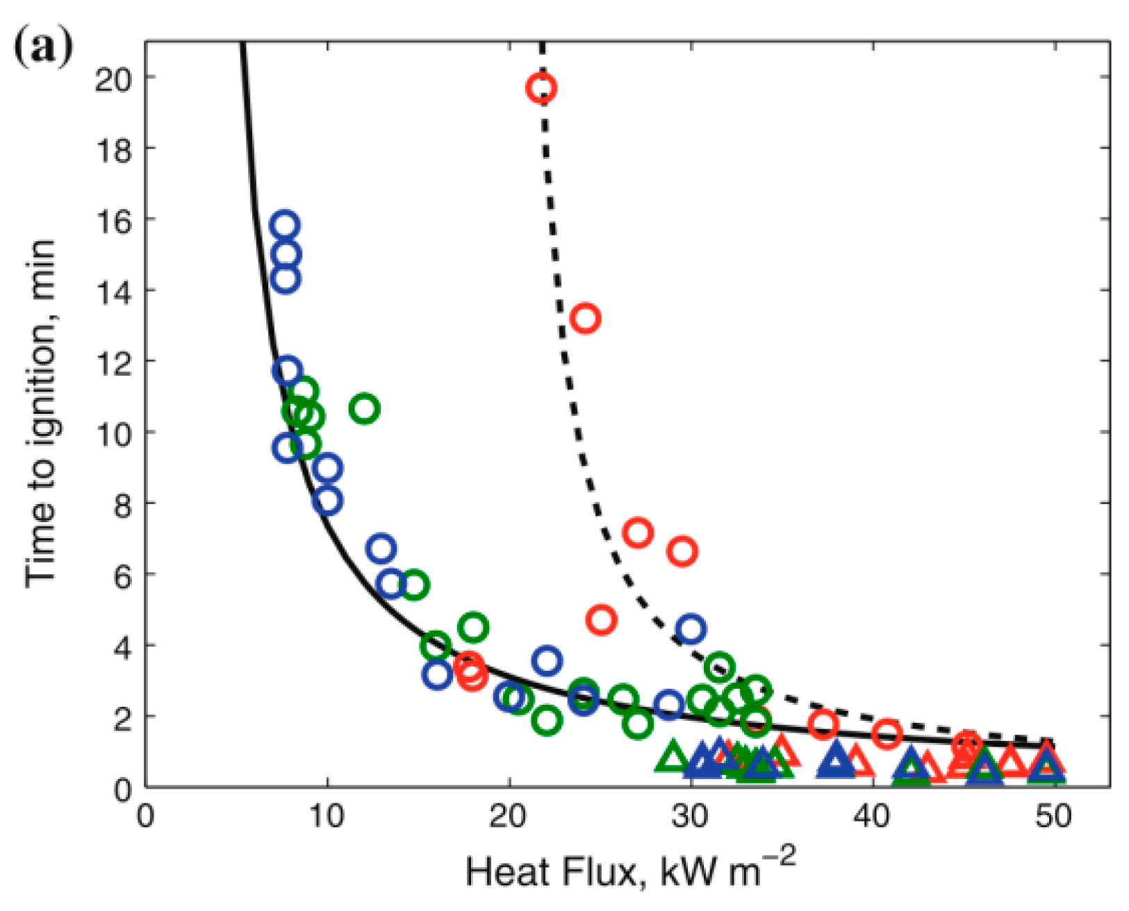
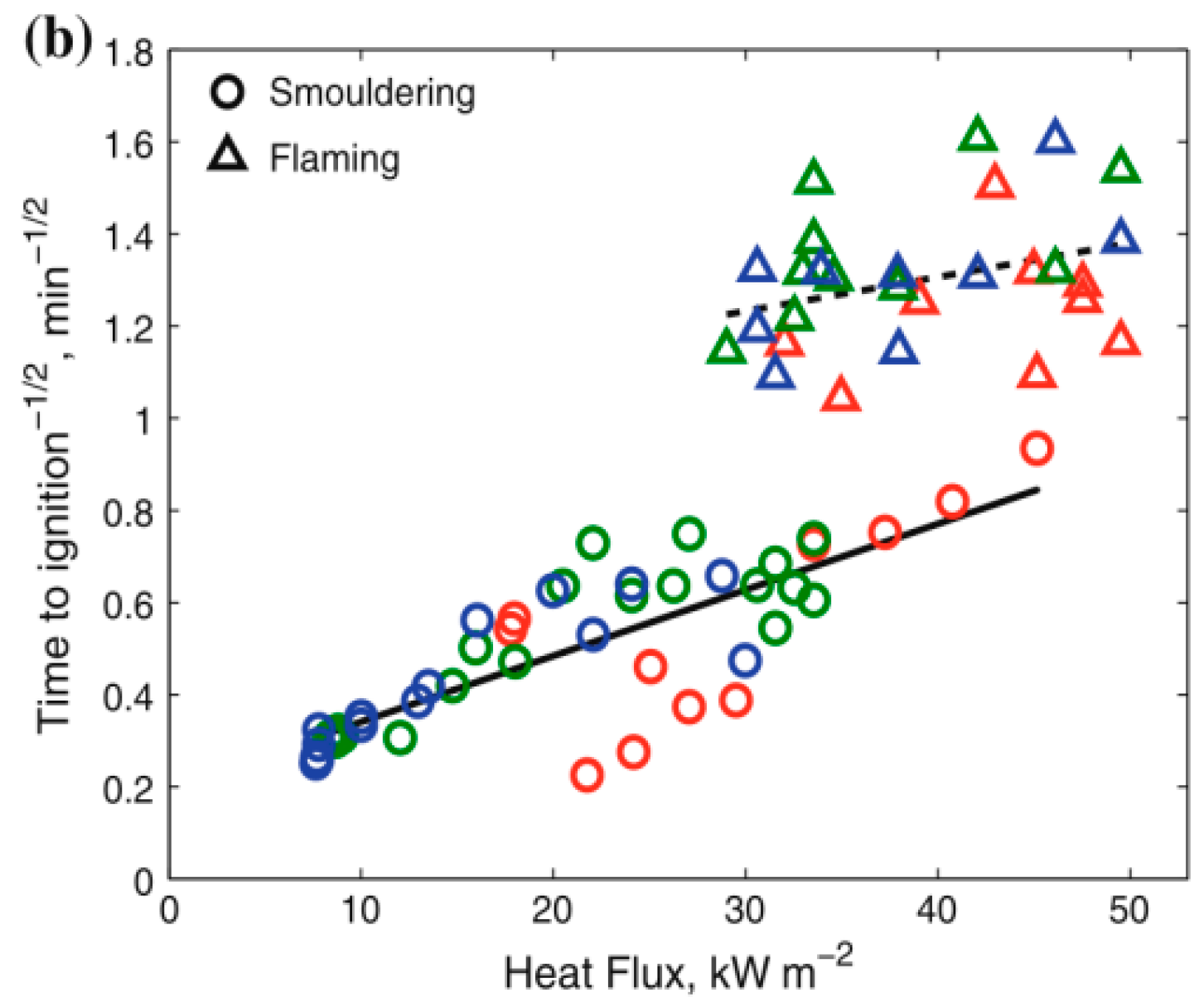
When the sample size decreased, the critical heat flux of both smoldering and flame ignition rose as shown in Figure 6 [60]. The sample size was demonstrated to have a great effect on the ignition of smoldering and blazing thermoplastic materials. The critical heat flux for smoldering and combustion was demonstrated to decrease with increasing sample size. For bigger samples, this association tended to be weakened.
Two different ignition patterns of PMMA plates were observed to occur more frequently in the recirculation zone and rarely at the end of the sample where the temperature was high and the flow rate was low. The increasing of step height extended the ignition limit and shortened the ignition delay, making it more favorable for ignition [61].

Ambient Conditions

Previous experiments in Hefei and Lhasa studied the impact factors, such as altitude [85], ambient pressure [10], and oxygen concentration [62]. The decrease in pressure caused the ignition time to decrease first and then increase until the ignition could not be achieved [10]. Hefei’s ignition time was shorter than Lhasa’s ignition time [85]. Due to the interaction between gas-phase O-2 and the polymer chain, it could lead to increasing random shearing and generating functional groups, which initiated depolarization. This improved method raised the instantaneous gasification rate, resulting in a shorter ignition time [62].

3.3. Melting and Dripping

3.3.1. Mechanism Analysis of Melting and Dripping

Melting is a process in which the kinetic energy of the molecules rises as the temperature rises, resulting in the destruction of crystallization and the transition of the substance from the crystalline to the liquid phase. Simultaneously, the liquid phase mobility improves and the liquid separates from the solid and produces molten falling droplets due to gravity. In a fire, the flowing and dropping fuel results in additional flames and induces thermal danger to nearby humans and properties. Thus, this kind of combustion parameter is of vital value to be researched. XPS foam is a widely used thermal insulation material because of its light weight, high thermal performance, strong resistance to corrosion, as well as low cost. A large number of previous studies had been done on the melting and dropping behaviors of flame spread on XPS surfaces.
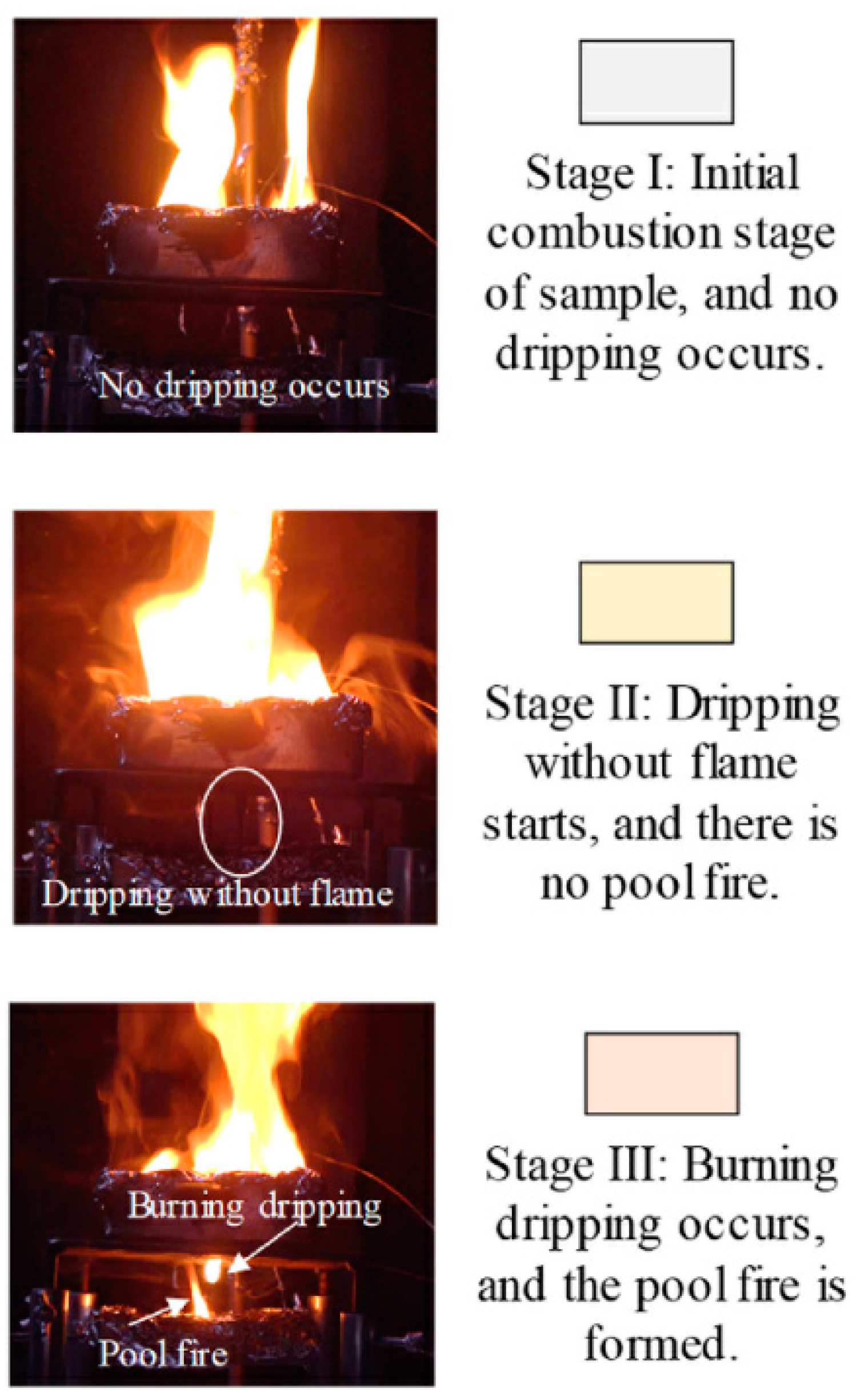
In terms of studying the mechanism of melting and dripping behavior, Zhang et al. [15] presented three stages of dripping while burning, as illustrated in Figure 7. The preliminary combustion stage, with no leaking, was the first phase. Stage II was associated with the beginning and expansion of dripping, while there was no flame detected. The first droplet indicated the beginning of Stage III, and the time when the pool fire burned out indicated the end.
In a word, melting and dripping during combustion have both positive and negative effects. They can limit the flame spread by eliminating heat and bulk from the pyrolysis region [103], but can also help the flame spread by igniting nearby objects (e.g., flaming drops or melt flow) [104,105].
Dripping had two competing impacts on ignitability in terms of Singh’s [103] research. They found that as the dripping became more prominent, according to the model put forward by Jian-Tao et al. [106], the thickness of the melting substance in the heated region decreased, pushing it to heat up rapidly. Instantaneous gasification took place at this stage, shortening the ignition delay period. It was interesting to note that the dripping accelerated when the viscosity was low, allowing the melting material to flow out fast before gasification took place, lowering the risk of an explosion.
The formation and growth of the pool fire is crucial to the downward burning and dripping. Luo et al. [104,105] investigated the dripping and melting methodologies of XPS foam downward flame spread. In 2017, they showed how a molten hot liquid layer formed and developed at the flame front area [63]. Actually, the downward burning over XPS foam may be seen as a tiny pool fire on top of the solid foam. As the flame front descended, the nearby solid fuel would melt, adding more liquid fuel to the pool. In 2019, they discovered that there was an inclination of the melting interface of XPS through experiments. The molten layer was thicker inside the condensed phase and got thinner near the sample surface. The melting liquid adhering to the rear wall greatly increased the molten layer’s thickness [105]. On the basis of the experiment, Luo et al. [104] concluded that the flame height rose in the stage of liquid fuel buildup, but fell when dripping. The FSR increased as a result of the melting of liquid fuel.

3.3.2. Influencing Factors of Melting and Dripping

In the aspect of factors influencing the melting, dripping, and flowing characteristics of substances in combustion, it can be broadly divided into the characteristics of the sample properties [107] (including geometric dimensions, such as width and thickness, etc.), façade structure [23,27], external environmental conditions [108] (including ambient wind, oxygen concentration, and pressure, etc.), and the introduction of flame retardants [109,110,111].

Sample Properties

A lot of previous studies have studied the effect of sample properties on the melting and dripping characteristics [107]. In comparison to PP slabs, the PE slabs melt, drip, and can be ignited earlier. Thinner slabs led to higher dripping frequency and smaller droplet diameter for both polymers [107]. Compared to the 2 cm and 3 cm samples, the maximum dripping mass of EPS or XPS was significantly larger when the thickness was 4 cm and 5 cm, which caused more melting material dripping into the pool fire zone [1].

Façade Structures

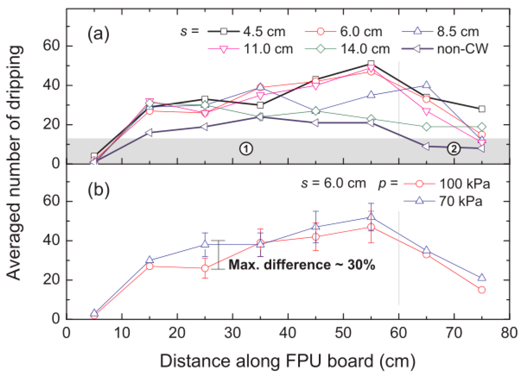
In studying the influence of the façade structure and characteristics on dripping and melting methodology of thick PMMA, it was found that the molten layer would not invade the materials for gypsum samples. However, the additional melting liquid was produced on the aluminum back wall, increasing dropping frequency of the droplets [23]. Xin Ma et al. [27] and Ran Tu et al. [2] conducted an experiment of how a curtain wall adjacent to a building façade affected the thermal and burning characteristics of flexible polyurethane insulation (FPU). At later stages of combustion, liquid generated from continuous melting and dripping behaviors were produced under the positive heat feedback from inner heat transfer to the still-unfinished ember layer, which was more pronounced for thinner space between the curtain wall and the samples. When there was no curtain wall, the melting and dripping behaviors merely occurred occasionally. Since the dripping phenomena were highly reliant on heat absorbed in the pyrolysis region, the amount of dripping generally rose, as depicted in Figure 8a, which was connected to the greater heat buildup by the curtain wall.

Ambient Conditions

Reducing pressure improved the dripping behaviors of three molten fuels [2]. The PE droplet’s combustion represented the typical d-square regulation, where K = 1.3 mm2/s. The calculated d-square of each PE droplet is shown in Figure 9. For all trials, the PE droplet’s d-square fell linearly as time passes and complied with the traditional d-square regulation [108].

Flame Retardant Treatment

With the development of technology, building materials are increasingly introducing flame retardant materials to reduce the combustion performance of insulation materials to achieve a certain safety performance. Some previous research investigated melting and dripping characteristics when flame retardants were added into the samples. The polyurethane sponge (PUS) had a graphene oxide (GO) nanocoating on its surface, which fully reduced the melt dripping of the sponge when exposed to a direct flame [109]. POG successfully restrained the melting and controlled the spread of the flames [110]. FR-2 and PNX were added to the flame-retarded foams to lessen their tendency to drip, and the PNX-containing foams had a much higher melt viscosity and better dripping behavior [111].

3.4. Flame Appearance

Flame is a common phenomenon in combustion that emits heat and light. The main flame parameters previously studied were flame shape [69,70,71,72,73] and flame height [74,75,76,77,78,79,80,81,82,83,84,85,86].

3.4.1. Mechanism Analysis of Flame Appearance

The study of flame appearance mainly included flame shape and geometry. Among them, the flame shape can be considerably altered by the material’s geometrical characteristics [64] as well as the surrounding wind [65,66], flow field, and magnetic field [67]. At the same time, many studies had experimentally investigated the flame geometry. Many empirical equations and phenomenological descriptions had been obtained.
Envelope flames and wake flames were identified as two flame modes [68]. Due to incomplete combustion of the material, the pressure gradient does not coincide with the density gradient, which tends to generate vortices and form streak flames [70].
It was found the flame changed from the shape of an inverted W to an inverted V during the combustion of the sample. The adjacent elevation angle has a non-linear effect on the flame height, because of the coupled influence of heat transfer, the chimney effect, and the radiation angle [31].
Most prediction models for flame height were based on the empirical flame height correlations [74].
X f = K Q ˙ n
KC Tsai [74] presented two new sets of data for measuring Q ˙ and X f , and a prediction model was obtained experimentally. The study found that the flame height correlates with Q ˙ .
Q ˙ < 20 kW : X f = 0.018 Q ˙ 1.00
For   Q ˙ > 20 kW : X f = 0.0667 Q ˙ 2 / 3
There was also a study of the structure and symmetry of materials. Yan [76] defined asymmetric factor and geometrical factor and discovered that as the geometrical factor increased, so did the flame height. According to the data, the fire hazard in U-shape geometry was far more dangerous than the fire hazard in flat-shape geometry. The flame height decreased as the asymmetric factor increased.
In addition to the study of flame height, there were also some former studies of flame thickness. Zhou found the vertical flame thickness rises first and obtains the maximum value after that falls. The equation among the maximum flame thickness, pyrolysis height, and width is as follows [77]:
δ max = 0.24 x P 0.51 w 0.32
The flame spread occurring in two successive modes had been found by Apte [83]. The flame was controlled in the boundary, which was seen as the first mode. It was a quick increment in the pyrolysis flux, inducing the formation of the plume during the transition to the second model. According to the study, the flame length x f was larger than the pyrolysis length. In the second mode, a correlation of x f   and the energy release rate Q ˙ showed as Equation (15).
x f   ~ ( Q ˙ U ) 1 3

3.4.2. Influencing Factors of Flame Appearance

Previous research showed that one of the most crucial factors influencing the rate of vertical flame spread was the flame height. Most of the previous studies measured the average height of the glowing flame tip using thermocouples.

Sample Properties

Many studies have examined the impact of an inclined angle on flame height. Weiguang An et al. simplified Quintiere’s correlation relationship of flame height and inclined angle, the equation was [72]:
x f   ( gcos ( π 2 α ) ) 1 / 3
The effects of the sample width were examined by Ma and Pizzo [20,81]. They found when the width of the simple increased, the flame height would be larger. Ma [81] found the flame height was determined by a coupling effect of width and heat flux and the equation to predict flame height was shown as follows:
Square : H 0 = 0.235 Q ˙ 0 2 / 5 1.02 D
Rectangular :   H = 0.035 ( δ Q ˙ 0 / l ) 2 / 3 , n > 3
There was also a study of air gaps on flame height. Xu [71] analyzed the impact on flame height considering air gaps (0–18 cm). The result showed the flame height increased initially and the turning point was approximately between 6 cm and 8 cm, after that it would decrease when the air gap increased.

Ambient Conditions

Previous studies had examined the influence of altitude and environmental pressure on flames. Zhao [80] studied theoretically the impacts of sample orientation and a unified correlation was created to forecast the frequency of flame pulsation:
f = 0.73 ( g * / D ) 0.42
St = 0.46 ( 1 / Fr * ) 0.53
Ma [72] and Gong [4] studied the impact of environmental pressure on flame height in quiescent air. Based on Gong’s [4] experimental results, Equation (21) could predict the flame height considering the environmental pressure:
H p 4.27 0.54 d
Considering the inclined angle, an empirical relation could be obtained as follow [72]:
H p 0.631 0.006 θ
For the same thickness and inclination angle of the sample, the flame height of Hefei was larger than that of the Lassa and the flame angle was smaller than that of the Lassa [112].

3.5. Burning Rate and Mass Loss Rate

3.5.1. Mechanism Analysis of Burning Rate and Mass Loss Rate

The abilities of a substance affecting the flame growth can be evaluated by lots of key parameters, including the burning rate (mass burning rate, MBR) and mass loss rate (MLR). They are crucial to determine the temperatures, lengths, and burnout of flames, all of which are key characteristics to establish fire development. The burning rate reflects the quantity of flammable material burned out in a given time, which defines the release of combustible gaseous products. Many previous studies had studied MBR and MLR [113,114,115].
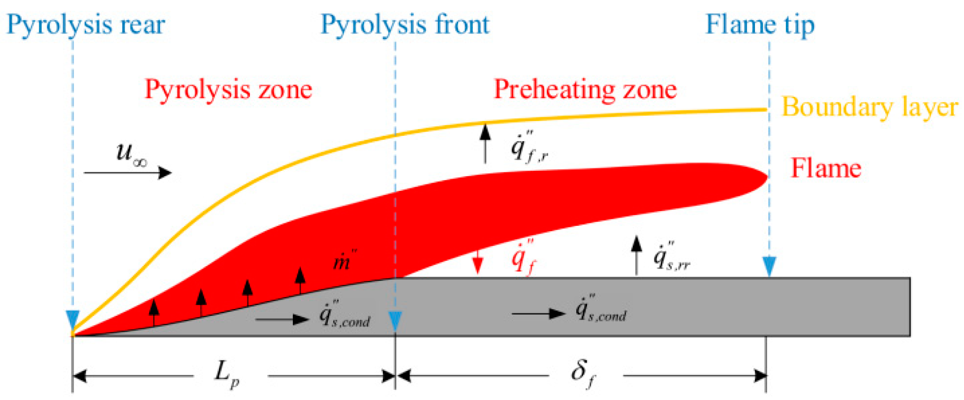
It was proposed by Carmignani et al. [113] that there was a correlation between the burn angle and MBR, from which the MBR could be calculated. In order to characterize the burn angle as a variable of fuel width, a straightforward phenomenological model, was then built. This model was successfully utilized to determine the average burning rate. The mass flow rate entering the control volume is (per unit width):
m ˙ in = ρ s V f τ
whereas the mass flow rate away is:
m ˙ out = m ˙ ¯ outL p = m ˙ ¯ out ( τ / sin β )
where L p refers to as the surface of the inclined pyrolysis region, or the hypotenuse of the triangle-shaped control volume and m ˙ ¯ out is the mass flow (averaged along Lp) exiting the pyrolysis area surface. Mass continuity must be satisfied:
m ˙ in = m ˙ out m ˙ ¯ out = ρ s V f sin β
In 2008, a number of numerical simulations were conducted by Y. Pizzo and J.L. Consalvi et al. [114,116] to calculate the steady-state local MBR of burning vertically oriented PMMA samples. The pyrolysis sheet was segmented into four areas vertically, as shown in Figure 10 [114]. As it was farther from the front margin, the local MBR showed a power law-like declination. The exponent for slabs with a width of more than 2.5 cm at the lowest area (x = 0 to 4 cm) was around −0.35. For 2.5 cm-slabs, the local MBR decreased more quickly, with a power function relationship of 0.8. The region from x = 10 to 18 cm, where the local MBR remained constant, was assumed to be the laminar/turbulent transition. The flow became entirely turbulent and MBR considerably increased with x in the higher zone.
The average mass flow exiting the burning surface was 9.54 g m−2 s−1, which was very similar to Singh et al.’s [115] measurement of 9.72 g m−2 s−1. There existed a great relationship between the MBR and the temperature gradient [115]:
m ˙ f = C s L g ( T * y * ) y * = 0
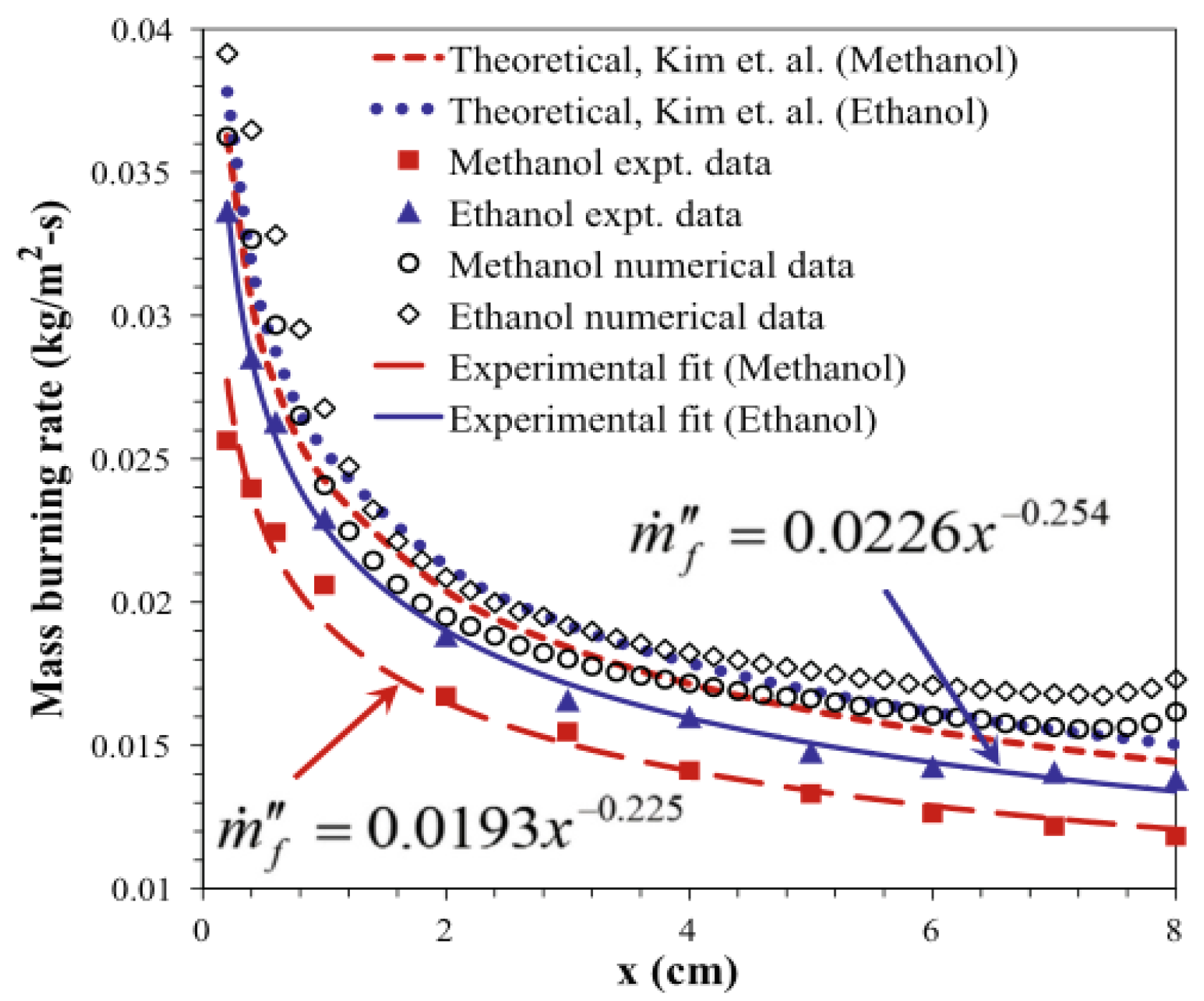
In Figure 11, the local MBR of the vertically oriented methanol and ethanol fires was highest on the leading edge and gradually decreased as they got closer to the following edge due to larger temperature gradients, stronger convective heat feedback, and tighter standoff distances. Additionally, both fuels’ local MBR were almost equivalent to x−1/4.
MLR is defined as the rate of variation in the mass of samples throughout the combustion process over time and represents how much material is thermally cracked, volatilized, and burned at a specific fire intensity. It is used as a standard to determine when the stable-stage starts. It was discovered that the changing trend of MLR and maximum flame height were similar. MLR was observed to change exponentially with time for the first and the third stages and remained constant for the second [117].

3.5.2. Influencing Factors of Burning Rate and Mass Loss Rate

A lot of previous research has studied the influencing factors on the burning rate and MLR. These influencing factors include the sample properties (including fuel coverage, inclination angle, etc.) [118,119], the façade structures [120], and the ambient conditions [121].

Sample Properties

To quantify the relationship between MLR and PMMA coverage, a logarithmic relation was put out in light of theoretical analysis and experimental data fitting [118], where f(F) was a coefficient,
m ˙ F = f ( F ) × m ˙
f ( F ) = 1 F + Clog ( F )
The inclination angle of fuel significantly also influences the MLR. The MBR in the steady-state increased with the increasing inclination angle of PMMA samples [119].

Façade Structures

The impact of neighboring façade inclination angles concerning combustion and flame spread of PU foam was once evaluated in studying the impact of façade structures on the MBR and MLR [31]. The largest thermal hazards were detected at a critical angle of around 90°, which matched with the MLR and flame height trends. As the curtain wall spacing grew, the MLR climbed initially before decreasing and peaked when the spacing was 13 mm [30]. When the geometrical factor (dimensionless depth) rose, MLR reached a limit [76]. The measured upward FSR increased with increasing HRR and decreasing EPS thickness, which was similar to the thermally thin material [120].

Ambient Conditions

A key factor influencing the flame spread is the ambient wind. The connection between the horizontal wind speed and the downward burning behavior of FPU was concluded [65]. Because of the lowered radiation angle coefficient from the flames, as well as the flame stripping and cooling effects brought on by increasing wind speed, MBR and melting/dripping rose firstly and subsequently dropped. It was discovered that the linear oxygen concentration-dependent behavior of MLR and the slab regression rate both reduced dramatically with the oxygen concentration [11,12]. Since more solid fuel volatiles were needed during ignition to maintain a complete reaction, it was discovered that ignition happened later and MLR rose in an oxygen-poor environment. By affecting pressure, altitude influences the amount of oxygen in the air, which, in turn, impacts the behaviors of combustion and flame spread. Upward and lateral FSR at high altitudes was half of that at a lower height [121]. Junhui Gong et al. [4] studied flame spread at three altitudes: Lhasa, Hefei, and Xining. As the atmospheric pressure dropped, the MBR also dropped. The final corrected connection between the MBR and pressure is as follows:
m ˙ p 1.8
which was similar to the classical relationship between the pool fire MBR and pressure:
m ˙ p 1.3
Mariusz Zarzecki et al. [5] studied how pressure and oxygen contents impact MBR. At low pressure, MLR dropped along with the MBR. As a result, a power law emerged:
m ˙ q ˙ ext q ˙ rr L = 64 ( p 1 / 2 Y O 2 , ) 1.3
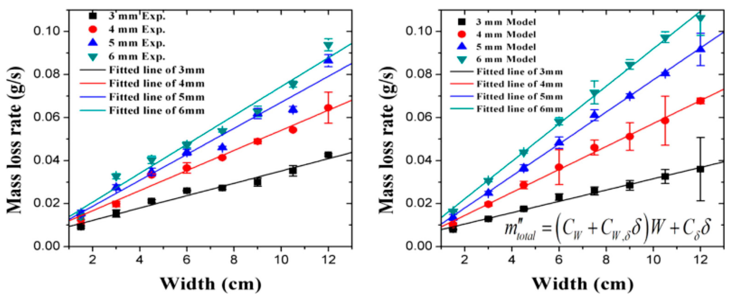
In studying the impact of external magnetic field gradients on the MBR, Zhang Zelin et al. discovered that the regression rates varied frequently, ranging from 32.5% to 10.8% [67]. The MBR was impacted by the magnetic force because it affected the flow field, which, in turn, influenced how the fuel received heat feedback and changed the temperature distribution. Fei Peng et al. [28,99] discovered that the MLR rose with decreasing ceiling height. The MBR changed the sample width and a power law was as follows:
m ˙ / W W 0.136 0.421 sin ( θ )
Additionally, the following was the stated exponential connection as Equation (33):
x p W 0.455 0.16 sin ( θ )

Flame Retardant Treatment

Stoliarov et al. [122] proposed a method to measure heat release through the increment of combustion products for materials treated with flame retardant. Based on this approach, they [123] also measured the mass loss and put forward a relationship between the burning rate and the flame retardant content through a series of experiments related to materials consisting of glass fiber-reinforced polybutylene terephthalate, aluminum diethyl phosphinate, and melamine polyphosphate.

3.6. Temperature and Heat Flow

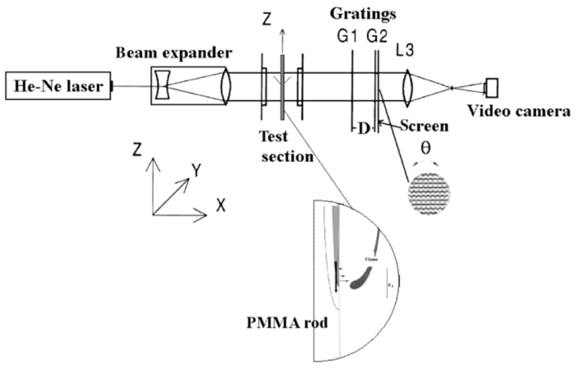
In the combustion process of materials, temperature and heat flow are often measured parameters, and many other characteristics can be determined from these two factors. Thermocouples and thermogravimetric analyzers are standard measuring tools, while laser holographic interferometry and infrared thermography are also frequently employed to quantify temperature. In addition, Juste et al. [88] created a new temperature extraction approach that combined the TFTM and the laser Mohr deflection method. Juste et al. [89] also conduct the error analysis between the thermocouple data and the new method. Figure 12 depicts a schematic representation of the Mohr deflection measurement system for temperature mapping.

3.6.1. Mechanism Analysis of Temperature and Heat Flow

Lots of scholars have conducted in-depth studies on temperature, Ajay V. Singh et al. [115] revealed a new relationship between the MBR of solid materials and the material surface temperature gradient. It could be expressed as Equation (34):
m ˙ f = C L ( T * y * ) y * = 0
Chu [124] discovered that ablation alters the damaged solid’s depth, which altered the temperature gradient within the solid. Vermesi et al. [125] encoded a one-dimensional model that was used to forecast and experimentally verify the temperature distribution at depth. The equations for mass, species, and energy were detailed in Equations (35)–(37), respectively.
ρ ¯ t = ω ˙ g
( ρ ¯ Y i ) t = ω ˙ di
( ρ ¯ h ¯ ) t = z ( k ¯ T z ) + ( ω ˙ di   ) Δ H s q r ˙ z
Korobeinichev et al. [126] used a heat and mass transfer-combined model with conservation equations for the gas-phase and solid-phase fuel in their study. Equation (38) described heat transfer in solid fuels.
ρ s C s T s t = x j λ s T s x j + ρ s W s Q s
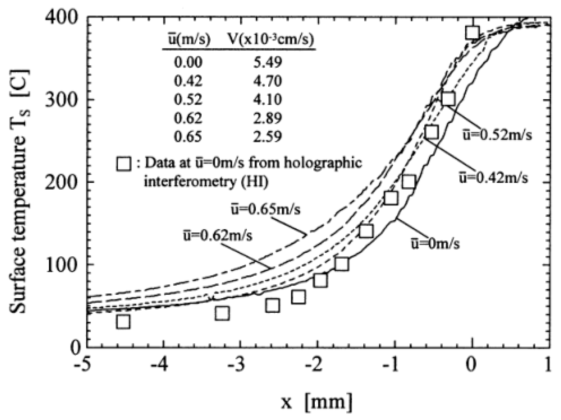
Some scholars have also conducted studies in the presence of wind. When the flame was growing close to its leading edge, Kudo [127] measured the temperature structure of the flame. Figure 13 depicted the temperature distribution measured by the temperature recording method at various reverse flow speeds at the middle of the sample width. By imposing steady-state pyrokinetics on the surface, Ramagopal Ananth et al. [128] used an iterative approach to obtain solutions to the Navier–Stokes (NS) equation for the temperature distribution of a flat PMMA plate. The NS solution demonstrated that, unlike the classical solution with the boundary layer (BL) approximation, Nu (combustion rate) was affected by the air velocity and the Reynolds number. As the surface temperature approached the flame “attachment” point, as shown in Figure 14, it increased abruptly to a maximum value and then began to decline as the boundary layer grew thicker.

3.6.2. Influencing Factors of Temperature and Heat Flow

Lots of previous studies had investigated the factors influencing temperature and heat flow. These influencing factors include sample properties (material width, material thickness, and inclination angle) [129,130], geometry [131,132], ambient conditions (wind speed, ambient pressure, magnetic field) [133], and the introduction of flame retardants [111,134].

Sample Properties

In the aspect of studying the sample properties, Weiguang An et al. [129] discovered that the average maximum flame temperature rose with the increasing sample width in their investigation of downward flame spread on XPS plates of various widths. Carminani [130] hypothesized that the average temperature in the pyrolysis region was affected by fuel thickness and that fuel thickness was inversely related to temperature. This prediction was verified by numerical solutions.

Façade Structures

In studying geometry as an influencing parameter on temperature, Weiguang An et al. [129] investigated the impact of sidewalls’ presence or absence on flame spread on XPS plates in 2014. The results showed that the average maximum flame temperature rose with sample width and was lower in sidewall-containing samples than in sidewall-free samples. For the samples with sidewalls, the temperature of the melting phase was higher. In 2017, Weiguang An et al. [131] investigated their role in the insertion of barrier layer experiments by varying the length of the barrier layer (L0) and the PS foam below the barrier layer (L). The area of the high temperature region was found to be affected by the length ratio (L/L0). Zhou et al. [132] conducted small-scale experiments indoors using EPS panels to systematically vary the spacing and width of the barriers. It was demonstrated that the temperature of the intermediate and sidewalls dramatically rose when the barrier distance grew from 30 cm to 90 cm. A larger barrier spacing implied a larger fuel width, which led to a higher flame temperature.

Ambient Conditions

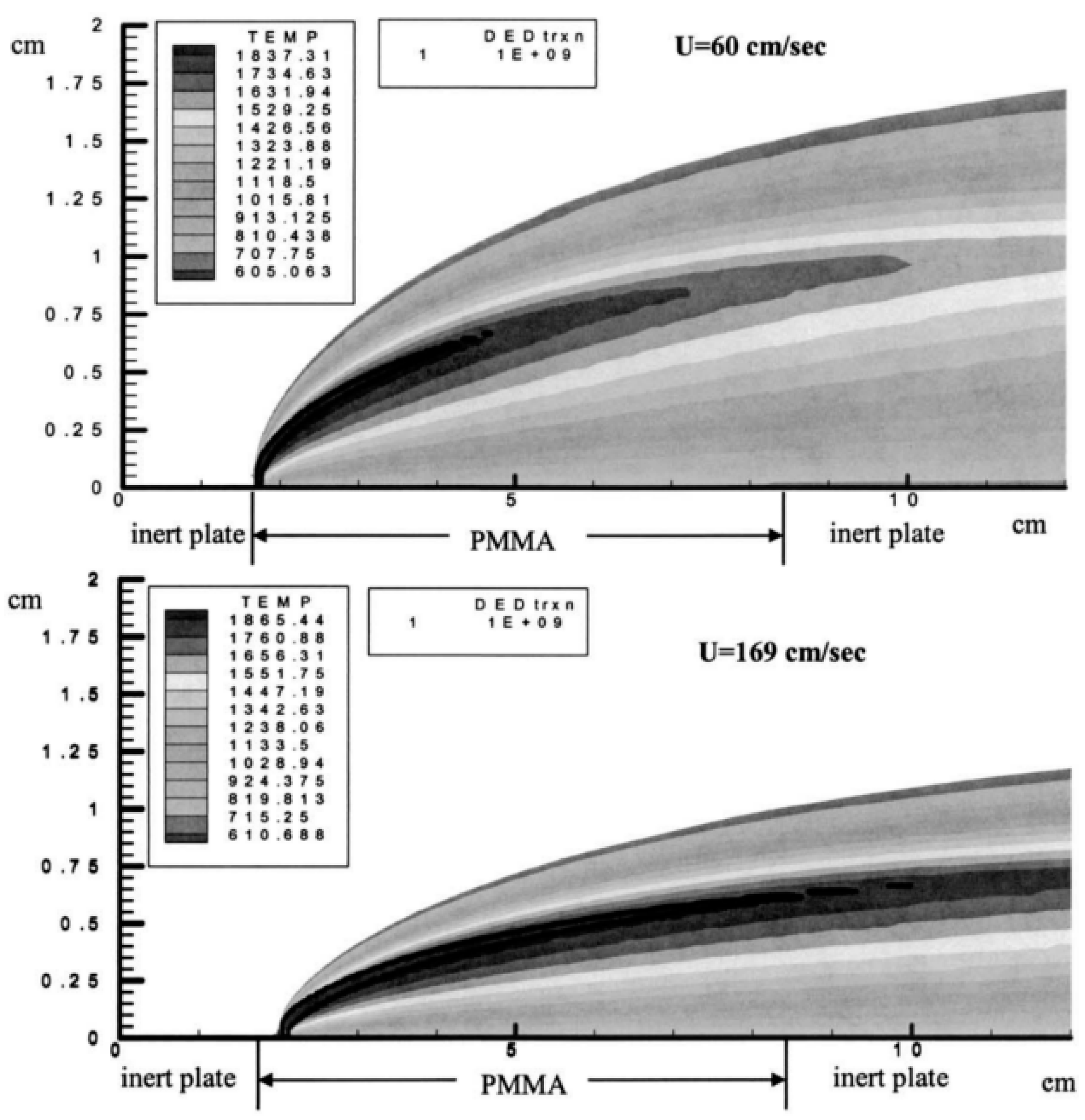
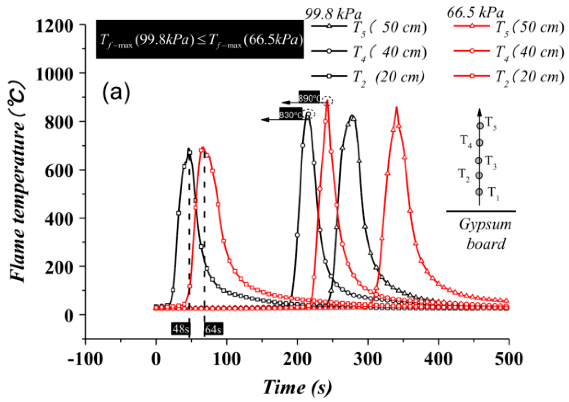
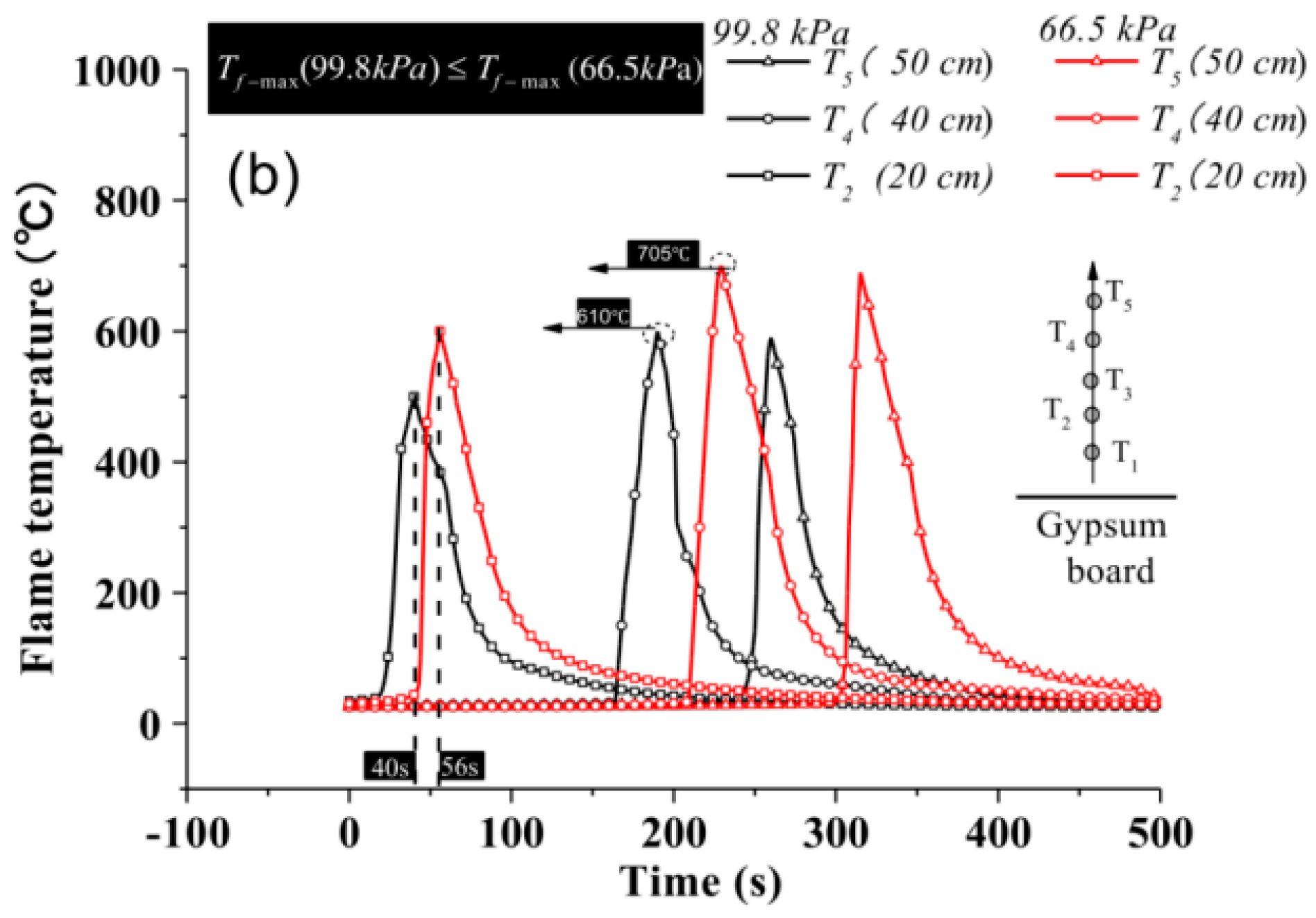
The ambient winds play an important role in the temperature. Zhou [65] investigated the temperature field at various wind speeds in an experimental study. The maximum temperature on both sides of the flame spread was nearly identical in the absence of wind. The results showed that temperature increased as the wind speed increased and that the windward zone had a lower temperature than the leeward area. Because of the intermittent flame immersion and the cooling influence of side wind, on the leeward side compared to the windward side, the near-field temperature was just a little higher. Some studies had also been conducted at different altitudes. Ma et al. [29] conducted experiments at different ambient pressures at Hefei (99.8 kPa) and Lhasa altitudes. The outcomes demonstrated that in the low-pressure environment, the maximum flame temperature was higher. Figure 15 depicted the axial temperature in the plume region. Other scholars had also conducted related studies at both locations. Li [133] discovered that the flame temperature was higher in Lhasa than it was in Hefei. Weiguang An [129] found that the flame temperature was higher at lower elevations than it was at higher elevations. In studying the magnetic field as an influence on temperature, the experimental research by Zhang et al. [67] revealed that the magnetic fields can modify the flow field to change the temperature distribution.

Flame Retardant Treatment

The addition of ATH to stiff polyurethane foam (PUF) as a flame retardant reduced the temperature around the material through heat absorption breakdown, according to combustion studies on PUF filled with a mixture of ATH and TPP [134]. Phosphoric acid ester (FR-2) was added to flexible polyurethane foam (FPUF) as a flame retardant [111]. The overlap of polymer decomposition and organophosphorus FR volatilization was found and the pyrolysis temperature decreased with an increasing amount of FR.

3.7. Gas Products

Various gaseous products can be produced during various combustion and pyrolysis experiments, which can be measured using the appropriate instrumentation. The composition and content of these gas products can be used to describe the degree of combustion.

3.7.1. Mechanism Analysis of Gas Products

Most of the mechanistic studies of gaseous products were based on experiments of flame spread. Korobeinichev et al. [90] measured the spatial variation of species concentrations in a flame using four PMMA samples. O2, CO2, and N2 were the primary gases of the flame. The concentration distribution of these substances determined the chemical composition of the flame. Shaklein et al. [91] conducted a numerical study through the heat and mass transfer-combined model of gas phase and solid fuel, which used a gas-phase two-step reaction mechanism. The pyrolysis of solid fuels produces gaseous products on the combustion surface. Such a relatively high-weight hydrocarbon decayed into a low-weight gas in the first reaction step, and then reacted with surrounding oxidants in the second reaction step. Gas-phase reactions rates were expressed as Equations (39) and (40):
W 1 = k 1 Y F 1 exp ( E 1 / R 0 T )
W 2 = k 2 Y F 2 Y O exp ( E 2 / R 0 T )

3.7.2. Influencing Factors of Gas Products

The generation of gas products is influenced by several aspects, including the sample properties (material placement angle) [135], ambient conditions (ignition position) [136], and flame retardants [137,138,139].

Sample Properties

PMMA samples in both the horizontal and vertical orientations were used in experimental and theoretical research under self-ignition conditions [135]. The findings demonstrated that vertical samples had lower CO yields and higher CO2 yields than horizontal samples.

Ambient Conditions

In an experiment, Wang et al. [136] conducted ignition at three places to analyze the influence of ignition locations on smoke generation. The findings indicated that the center to lower edge of the ignition position produced the maximum CO concentration.

Flame Retardant Treatment

The generation of gas products can also be affected by flame retardants. Combustion tests of flame retardant polyurethane foams [135] revealed a significant reduction in CO and CO2 generation compared to pure PU foams. The hybrid material was developed by changing the mixing ratio of polyisocyanate and sodium silicate solution [137]. This hybrid material produced less CO2 and carbon monoxide than rigid polyurethane. A variety of novel APEA flame retardants were made by using different mass ratios of ATH [138]. It was found that the addition of ATH formed more phosphorus-containing cross-linked carbon and aromatic carbon during combustion, which effectively reduced heat release and smoke generation. Another study added a flame retardant coating to the surface of RPUF [139] and found that the coated RPUF had a lower total smoke output compared to pure RPUF.

4. Flame Spread of Thermoplastic Materials

4.1. Natural Horizontal Flame Spread

The flame spread was a consequence of a series of complex physical and chemical changes together, including solid pyrolysis, combustion and thermal diffusion of combustible gases, and heat conduction. Meanwhile, the complexity of the flame spread process was also influenced by many other factors. Theoretical models were usually studied in two categories: gas-phase models and solid-phase models.

4.1.1. Mechanism Analysis of Natural Horizontal Flame Spread

Karpov [140] analyzed the natural flame spread over PMMA by describing a model of thermal feedback and mass transfer.
Gas-phase equations:
γ = 1 2 ( γ i X i + 1 γ i X i )
Heat and mass transfer in solid-phase:
V s ( x ) = L s ( x ) 0 W s dy
Combustion and pyrolysis model:
W s = ( 1 α ) n k s exp ( E s / R 0 T s )
Radiation model:
X j q j r = k ( 4 σ T 4 G )
Boundary conditions:
ρ D Y i y + ρ vY i = 0 ,   i = { O , P }
Combustion in narrow channels between parallel plates has been performed. The natural convection is suppressed in this experimental setup that reproduces the formation of a finger pattern under normal gravity [141,142]. Subsequently, Matsuoka [143] found that on non-carbon ring materials, the early uniformity of the flame front decomposed into many small tips and then showed finger patterns when it approached nearly the extinction limit. This is the first time that finger patterns over the thick sample had been found, though this finger pattern had already been found in the thin sample [144]. Based on previous studies about the Lewis number, Kuwana [93,94,95] proposed the effective Lewis number [92]:
Le eff , mod = Le 2 β ( lnU 1 + k U 2 )

4.1.2. Influencing Factors of Natural Horizontal Flame Spread

The former studies of natural horizontal flame spread are mainly as follows: sample properties (width, angle, and thickness) [96,97,98], ceiling properties [99], and ambient conditions [100] (altitude, ambient pressure, and microgravity).

Sample Properties

On one hand, the sample’s moisture content can consume some of the heat to reduce the FSR. On the other hand, the moisture content increases the convective heat transfer, which could lead the FSR to increase [96].
The impact of the sample’s inclined angle on FSR had been studied by Weiguang An [22] and Chen [97] et al. Weiguang An [22] found the FSR first decreased and then increased as the width of the sample increased when the sample’s angle was smaller. And this trend was contrary when the sample’s angle was larger. Chen [97] obtained a model to predict the value of V f :
V f = sin 1 / 2 θ
At the same time, Weiguang An [22] obtained an equation to estimate the flame spread rate considering an inclined angle.
V f = ce psin α ( α / 2 )
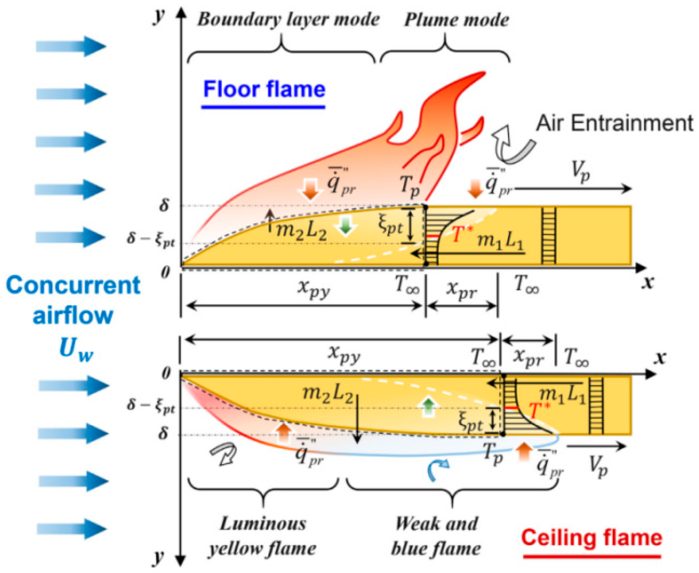
Moreover, ceiling flame and floor flame were the typical scenarios for the basic diffuse combustion problem and horizontal flame spread. The concurrent floor and ceiling flame spread models were shown in Figure 16. Ma [98] found the FSR increased as the sample thickness decreased. Sample thickness has a greater impact on ceiling flames than floor flames.

Ambient Conditions

The flame spread under the ceiling was also studied by many people. Peng [28] proposed that the FSR of a narrow sample tends to decrease and then increase with the increase of ceiling inclination angle, but the FSR over a wider sample decreased with the increase of ceiling inclination angle. The burn rate was a power function of sample width. The equation was shown as follows:
m / W W ˙ 0.136 0.421 sin α
The empirical model for predicting the pyrolysis length considering the couple influence of sample width and the ceiling inclination angle was shown as follows:
x p W 0.455 0.16 sin α
Because the burning zone increased with a decrease in ceiling height, this meant that the convective heat flow would drop significantly with a decrease in ceiling height, and it would also lead the flame spread rate decrease. The inclination curve progressively became flat and finally disappeared when the ceiling height increased. The increased radiant heat feedback, it could be said, mostly accounted for the rise in flame spread rate. In Hefei, FSR increased when the sample width increased and decreased as the ceiling height increased [99]. The relationship between the FSR and simple width in Lhasa was contrary to that in Hefei.
According to the former study, Zhou [100] found the FSR decreased when the sample width increased and proposed a negative power function relationship considering altitude:
V f W m
Plus, a relationship between FSR and altitude is the same as that of sample width.
V f P j
For the same thickness of the sample, the FSR at the low altitude is smaller than that at the high altitude [145]. Both FSR and LBR decreased obviously in low pressure environments. The FSR was a function of the 2/3 power of environmental pressure [146]. Regardless of the altitude, the FSR was proportional to the external radiation intensity [147].
Combustion of thermoplastic materials under oxygen-limited conditions leads to the formation of finger patterns [148]. Once it occurs, it will result in a serious flame. This was the reason why it was important to study this.
Thereafter, the small flames are called fingers, regardless they are induced by combustion or smoldering combustion. Kuwana et al. [93,94,95] modified the theory of the Lewis number and proposed the impactive Lewis number [92] as the dominating factor. It will form a finger pattern and the impact of convection on finger pattern formation is small when the Lewis number is less than 1. Furthermore, the theory of Kuwana [149] about smoldering was improved and the modified impactive Lewis number had been proposed according to Kuwana’s theory:
Le eff , mod = Le 2 β ( lnU 1 + k U 2 )
Here, the Lewis number is Le = α ¯ D .

Flame Retardant Treatment

The heat flux is affected by the sand layer, and the heat flux can affect FSR [150]. FSR increased as the sand size increased and decreased as the sand thickness increased. Trubachev [73] found that the PMMA +10%TPP was an available retardant measure using a restriction of the gas-phase combustion reaction.

4.2. Horizontal Concurrent-Flow Flame Spread

Because of the existence of ambient winds, the flame spread will pass a transition process to a new steady state. However, this transition has very rarely been studied, although it occurs frequently in many flame events.

4.2.1. Mechanism Analysis of Horizontal Concurrent-Flow Flame Spread

The behavior of the transition phase in horizontal flame spread under concurrent-flow was studied experimentally [151]. The progress of concurrent-flow flame spread was shown in Figure 17.
The thickness of the rear end of the fuel was reduced during the transition stage, resulting in a faster return at the back end of the sample. When airflow was present, the sample thickness end reduced, increasing the q ˙ f . c to the pyrolysis rear. Both the evolution of the fuel-rear regression rate and influence factors (opposing air flow, sample thickness, and pyrolysis duration) changed during the whole transition stage. The shift for fuel-rear regression rate was obviously longer than the FSR. The fuel-rear regression rate obtained the maximum value when the simple thickness was very thin, and then, it will become a fixed value.

4.2.2. Influencing Factors of Horizontal Concurrent-Flow Flame Spread

The previous literature of horizontal concurrent-flow flame spread is mainly focused on sample width [152], microgravity [86], and ambient airflow velocity [153].

Sample Properties

The impacts of the width of the sample on flame spread under concurrent flow were studied [152]. For samples with a width of ≥10 cm, the flame spread showed a weak relationship with the width of sample.

Ambient Conditions

The process of flame spread was complicated by the interaction of flow rate, turbulence intensity, and oxygen content. Y. H. Chao et al. [154] investigated the FSR, flame duration, surface heat flow, waste gas temperature, combustion by-products, and smoke using fuel (PMMA). A flow’s oxygen contents–mass equilibrium was also used to get a flame length expression. This expression produced good heat flux and flame length correlations, especially when the flow rates were high where buoyancy was less of a factor, and full combustion took place at high oxygen concentrations. Microgravity tests performed by Yanjun Li et al. [86] illustrated how confinement affects the burning behavior of polymeric solids. Through the use of parallel, double-sided, and single-sided samples, three distinct burning situations were evaluated. Across the examined range, the same limited situation, flame height, and FSR were positively related to the flow velocity. The flame length and FSR originally increased when confinement (or H) climbed before decreasing. Additionally, the quenching flow speed decreased when H fell before ultimately rising.

4.3. Horizontal Opposed-Flow Flame Spread

4.3.1. Mechanism Analysis of Horizontal Opposed-Flow Flame Spread

The heat regime was regarded as an important regime, so De Ris and Delichatsios [155,156] proposed a solution for the FSR, respectively. When the flow velocity of the air was very small, the length where the oxidizer passed through is:
  L g = α g / V g
The residence time the oxidizer passed through is:
t res L g / V g = α g   / V g 2
It was fast enough for combustion and pyrolysis. At the same time, V g was assumed to be very high and t res was quite tiny by comparison with the radiation time [157]. A balance between heat transfer and the energy required to make the sample from T to T v could provide the same result as De Ris and Delichatsios [155,156]. The FSR was not influenced by flow velocity V g , inversely, it was influenced by the sample thickness, and was directly proportional to the sample thickness and the De Ris factor F.
F = ( T f T v ) / ( T v T )
Bhattacharjee derived an expression for the diffusivity of convective flame diffusion for thin and thick fuels under microgravity conditions using a simplified analysis [158].
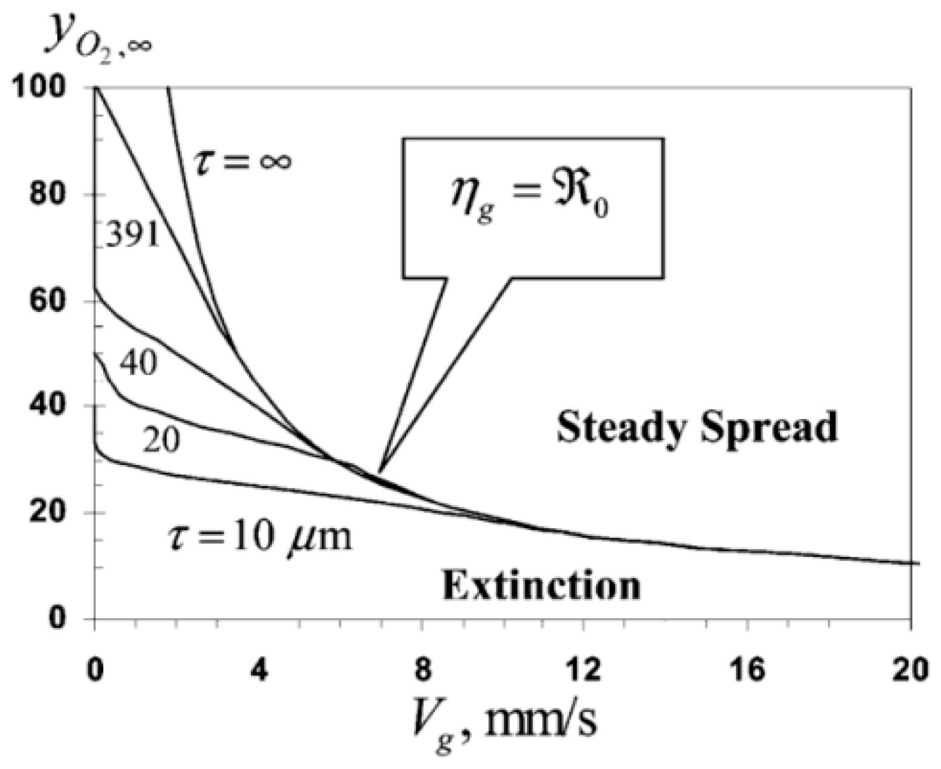
Figure 18 showed that when the thickness of the fuel was fixed, the oxygen levels required to maintain a stable spread decreased as V g increased. When the value of V g was fixed, the limiting oxygen content increased as long as R 0 < 1. As y 0 2 , decreased, the value of R 0 increased until R 0 =   n g = 1. So, thickness had no influence on flammability limits if R 0 ≥ 1.
The equation of the FSR over thermally thin samples could be shown as follow:
V f , thermal = π 4 λ g ρ s C s τ F  
where,
F T f T v T v T
FSR in the radiative regime was shown as follow:
V f . rad ~ V f . thermal ( 1 R 0 n g )

4.3.2. Influencing Factors of Horizontal Opposed-Flow Flame Spread

Sample Properties

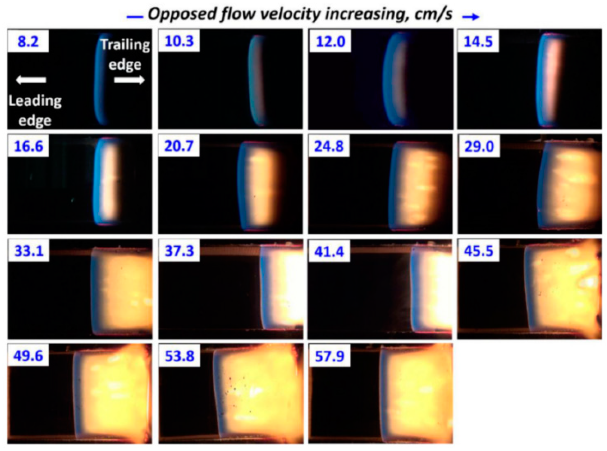
Flame spread over the sample with different thicknesses in an opposed flow had been studied by Hossain [159]. When the sample thickness was lower than 12.1 mm, they were completely burned out when the flow rate was >30 cm/s, which meant the critical flow rate was 30 cm/s. In this range, flame spread may be independent of the flow rate: this was determined as a regressive combustion regime. The samples with 24.5 mm thickness did never burned out in Hossain’s study, but they reached a regressive burning regime when the velocity reached 41.4 cm/s. Figure 19 shows the opposed-flow velocities and surface velocities.
The decrease in the sample temperature and the temperature of the incoming oxidizer at the flame front caused a decrease in the local FSR along the flame spread distance. In addition, the FSR decreased as the local Brot number increased when the sample temperature was the same [160].

Ambient Conditions

In space, thin thermoplastic materials were ignited in a flow tunnel under opposed flow [161].
Figure 20 showed that the estimated flame’s length (about 40 mm) almost matched the size of the top view of the flame.
It was found that the flame color changed from yellow to blue with the decreasing flow rate under microgravity conditions. The yellow flame was mainly caused by the soot radiation. As the flow rate decreased further, the flame became longer, and its shape became more spherical. The blue flame in microgravity showed a lower concentration of soot in the flame compared with that under normal gravity.

4.4. Vertical Concurrent-Flow Flame Spread

4.4.1. Mechanism Analysis of Vertical Concurrent-Flow Flame Spread

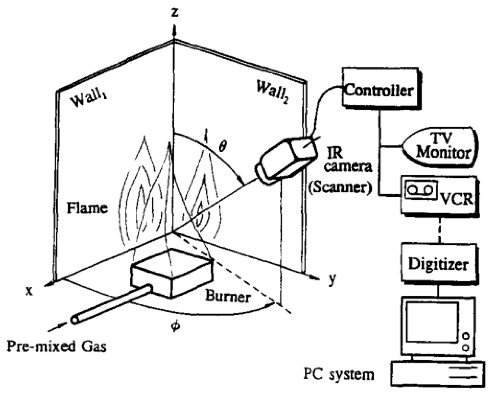
Flame spread is usually categorized as either concurrent-flow flame spread or opposed-flow flame spread. The flow direction opposes the direction of oxygen diffusion, resulting in a constant FSR. However, there was considerably less knowledge about concurrent-flow flame spread over vertically oriented surfaces driven by buoyancy. To calculate the pyrolysis front spread rate, transient temperature profiles are necessary. An automated infrared imaging system, as shown in Figure 21, was applied by A. Arakawa et al. [162] to gather 2D wall surface temperature data in a rather wide area and solve the implementation and ocular observation challenges. The system successfully avoided flame interferences, and measured the temperature distribution the of flame-heated wall from which the spread rate was calculated. It was a novel experimental measuring approach for wall flames.
A roughly resembling solution using a subtitling coordinate framework near the pyrolysis front was the basis for early theoretical predictions of turbulent flame spread. Additionally, the heat conduction equations in the steady-state solid phase were found by assuming a material that was either thermally thin or thick. Delichatsios, Ma et al. [163] used a numerical simulation and similarity solutions for vertical concurrent-flow flame spread to predict and analyze upward FSR on PMMA. The following coordinate system could be used to indicate the location of the pyrolysis front:
Z p l = fcn ( t τ p ,   z po l )
where τ p is a characteristic pyrolysis/ignition time:
τ p = π 4 k ρ c ( T p T ) 2 [ q ˙ 0.64 σ ( T p 4 T 4 ) ] 2
A combustion-related length scale:
l = ( q ˙ net Δ H c Δ H v 1 ρ c g T g ) 2
and z po is the initially pyrolyzing region.
q ˙ net = q ˙ w σ ( T p 4 T 4 )
and for Z p <   1.8 m , q ˙ w 26 kW / m 2 is essentially independent of material. Quintiere, J.Q. et al. [164] used a Volterra integral equation and a transient, non-charring burning rate model to solve the upward FSR and researched the impact of ignitor properties and burning duration on upward wall flame spread. Consalvi, J.L. et al. [165] presented a thorough study of the heat-up of the unburned material during vertical concurrent-flow flame spread over PMMA. The entire wall heat flow distribution was scaled appropriately based on:
ξ = ( x x p ) / ( x fl x p )
allowing the location of the plume zone above 1.6 and the intermittent flame region between 0 and 0.4. Both continuous and intermittent flames were crucial for heating the unburned solid fuel.
Direct numerical simulation (DNS), a technique of availability of high-performance computing, broke the limits of pre-existing models of flame spread. To model concurrent-flow flame spread on PMMA at varied inclination degrees, a fully connected 2D fluid-solid DNS methodology was created, which reduced computing costs compared to the DNS [166].

4.4.2. Influencing Factors of Vertical Concurrent-Flow Flame Spread

The characteristics of vertical concurrent-flow flame spread are influenced by a lot of factors, including the sample properties (width and thickness, inclination, etc.) [167,168,169,170,171,172] and external conditions (façade structures and ambient conditions including oxygen concentration, etc.) [173,174,175,176,177,178,179,180].

Sample Properties

In aspects of the sample properties, Kuang-Chung Tsai et al. [19] and Y. Pizzo et al. [20] studied the effect of a material’s width on the flame spread on PMMA. Kuang-Chung Tsai et al. found that FSR and width had a power relationship of 0.35, with broader flames spreading more quickly than narrower ones. Y. Pizzo et al. [20] observed a change in the flame’s laminar to a turbulent state for narrower slabs. The FSR declined with the increasing slab width. The HRR per unit width was found to be much lower at w = 0.025 m, which, in return, resulted in a drop in flame height. Yang Zhou et al. [169] discovered that using a modified Rayleigh number, the befitting relationships between pyrolysis length and flame length may be identified and categorized according to the sample inclination angle. At 10° to 40°, 50° to 70°, and over 80°, respectively, the derived equations relating flame height and HRR per unit width have power exponents of n = 1, n ˂ 1, and n > 1. Additionally, the dimensionless MLR, which itself was proportional to the 1/4 power, and the revised Rayleigh number were nearly inversely related. There was a nearly exponential connection between sine of the inclination angle and the vertical concurrent-flow FSR.
A hazardous flame configuration is one in which the flame spread and the direction of the induced airflow are the same in vertical concurrent-flow flames spread across discrete fuel arrays. Colin H. Miller et al. [170] investigated vertical arrays of alternate PMMA lengths for the spread of vertical concurrent-flow flame on distinct fuels. The FSR was maximum when f = 0.67, potentially as a result of a postponed barrier layer thickening or growing air entrainment. Arrays with f ≤ 0.5 experienced a drop in FSR. Rongwei Bu et al. [172] and Zhe Wang et al. [171] both studied the cumulative impact of array fuel bed width, n, and fuel inclination angle over discrete PMMA and XPS, respectively. When n > 1, the average FSR was shown to have nothing to do with n. When n > 5, air entrainment limited the MLR per total mass. Additionally, there was a definitely positive association between fuel coverage and the FSR [21]. The FSR increased when the inclination angle ≤ 90°. The average flame height, FSR, and melt zone length all reduced as the inclination angle rose. An empirical equation relating the FSR and inclination angle is as follows:
v f cos π 2 θ 4 5 L x p 2 5
Additionally, it was discovered that when the inclination angle grew, the predominant mode of heat transmission switched from radiant to convective [172].

Façade Structures

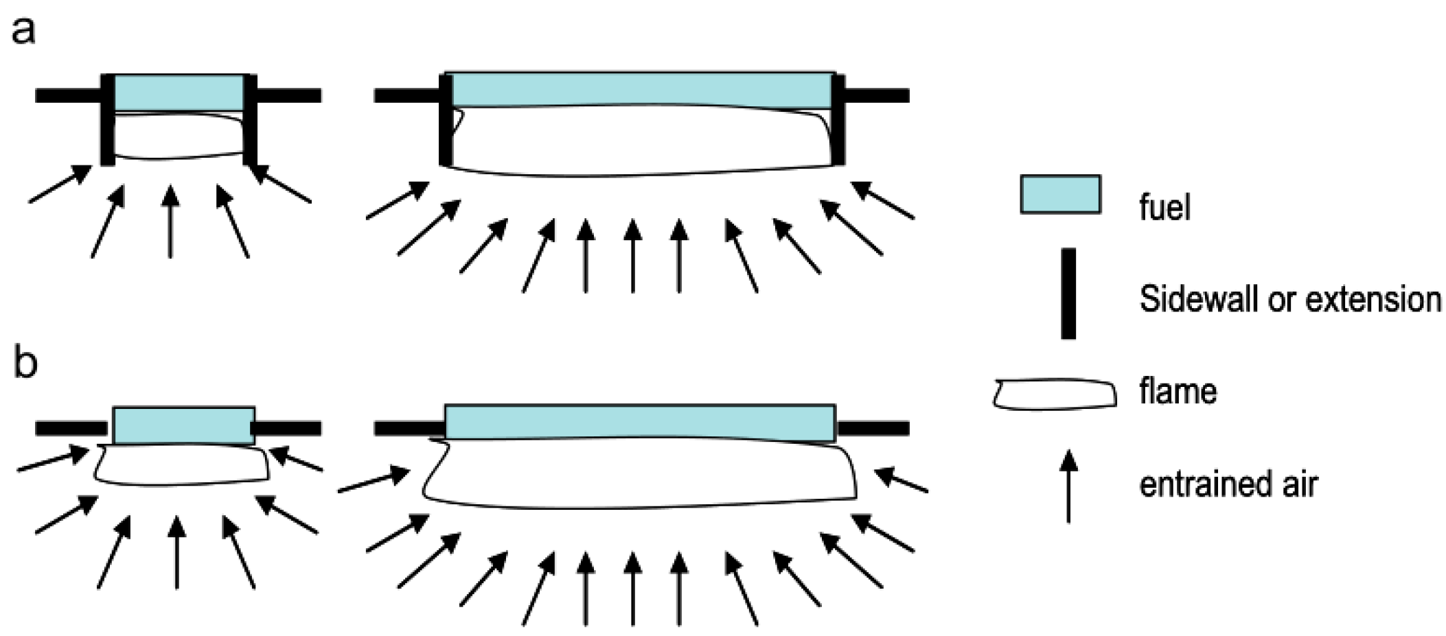
The façade structures include the existence and the spacing of curtain walls, and the existence of concave (U-shaped) structures, etc. Weiguang An et al. [173] conducted an experimental analysis of the behavior of XPS’s vertical concurrent-flow flame spread with a changing curtain wall shielding rate in a vertical-oriented channel. At the location in the channel center, 2 cm out from the XPS surface, the maximum temperature initially rose and then decreased as the curtain wall shielding rate increased. The former was greater than the latter. When the shielding rate grew, so did the average flame height and FSR. In addition, Weiguang An et al. [174] experimentally studied the combing effects of structure factor ( Π ) of the channel and curtain wall coverage rate ( r ). Upward FSR firstly decreased and then inclined as r increased. While 0 ≤ r < 0.2, the inhibiting influence of channel on air entrainment dominated. When 0.2 ≤ r ≤ 0.8, what dominated was the heat feedback from the curtain wall, FSR increased with increasing Π . The influence of Π on FSR was not significant when r = 0. Hui Zhu et al. [84] studied how the wall and thin fuel spacing influenced vertical concurrent-flow flame spread. The pyrolysis height and burnout length both exhibited the law of firstly rising followed by dropping with increasing separation. Due to increased radiation fluxes, the MLR attained its maximum, where the ratio of wall spacing/sample height was with a value of 0.065. To study the concave (U-shaped) façade structure, the sidewall structures were required to be researched first. Kuang-Chung Tsai [32] performed experiments without sidewalls using PMMA slabs with different widths and proposed a hypothesis of the sidewall effects as shown in Figure 22. When there were no sidewalls, the width effects continued to exist. Wider flames had a higher flame height and FSR. Sidewalls prolonged flame heights in comparison to flames without sidewalls. The narrower flames with less heat feedback along the flame centerline had larger FSR.
When studying the influence of concave structure on vertical concurrent-flow flame spread, Weiguang An et al. [33] found a considerable variation in the XPS flame front, whereas the pyrolysis front movement was largely steady. FSR increased at a rate of 27.76% when G increased from 0 to 0.8, but only at a rate of 7.33% when G increased from 0.8 to 1.6. Additionally, as illustrated in Figure 23, a prediction model was developed to assess how the concave shape affected the XPS’s flame spread properties. The material surface and sidewall were flush in Figure 23a. In this condition, the pyrolysis region height was x p 0 , and the flame height was x f 0 . In Figure 23b, the sidewall width was larger than d. A dimensionless upward FSR formula under the U-shaped structure was proposed by Weiguang An et al.:
v fu v f 0 1 F ( Π ) 1 F ( 0 ) . U 2 k 4 1 / 2 n 1 U 1 / n 1 x f 0 1 / 2 n 1 1 1 x p 0 / x f 0
To further investigate the impact of the U-shaped structure, it was discovered that the upward FSR and XPS’s flame height both rose together with the geometrical form factor [175]. In addition, the impact of the concave façade geometry on the upward spreading flame at different altitudes was studied and a chimney-like effect theory was put forward. In both plain and plateau, the FSR and the MLR both increased with the growth of the U-shaped geometry factor [6]. PMMA heat transmission and upward flame spread under various U-shaped construction parameters were explored by Weiguang An et al. [34]. FSR increased as Π rose for Π < 1 and tend to be unchanged for Π ≥ 1. Theoretically, the flame height and pyrolysis length were correlated as follows:
x fu = 1.639   x pu
which basically matched with experimental data when Π was equal to 0.4 or Π was equal to 1.6.

Ambient Conditions

In studying the influence of altitudes and oxygen contents on vertical concurrent-flow flame spreading behaviors, experiments of PMMA vertically concurrent-flow flame spreads were done in Hefei and Lhasa [177]. The transitional, laminar, and turbulent flow zones, respectively, corresponded to the three stages of the flame spread. Compared to Hefei, the change to a turbulent flow spent more time in Lhasa. Since there was less heat flow due to the lower pressure, FSR in Lhasa was almost half that of Hefei. Xinjie Huang et al. [7,176] found that the FSR decreased as the altitude increased. Later, while the pyrolysis front was at its sluggish stage, FSR accelerated at high altitude. The smoke produced in the pool fire zone influenced on the oxygen content in the air entrainment, and XPS occurred on the plateau, leading to extinction and secondary ignition. The FSR of EPS increased as the inclination angle increased in Hefei and Lhasa as well. To provide a thorough grasp of how sample inclination and ambient pressure interact to affect how flames spread across RPU foam, Yang Zhou et al. [7] found the suppression phenomena under the competing impact of surface charring, gas-phase heat transport, and the critical extinction angle was: θcrit, max was equal to 85° when P was equal to 100.8 kPa; theta (crit, max) was equal to 60°, θcrit, min was equal to 25° when P was equal to 65.5 kPa. An incremental correlation to assess the FSR was constructed according to the laminar and turbulent flow modes. As a further comparative research of Yang Zhou et al.’s previous work, three pressures and four inclination angles on the surface of the fuel were applied by Ran Tu et al. [8], respectively. To demonstrate the trend of FSR using pressure, inclination, and other variables, a semi-quantitative connection was devised and established.
Flammable thermoplastics were commonly employed in manned space travel in microgravity, resulting in fire danger. Future exploration mission design has given careful emphasis to spacecraft flame safety. Because of the weak buoyancy flow and the longer flame preheating period, microgravity flame spread occurs more quickly than that in normal gravity [180]. Concurrent-flow flame spread experiments using PMMA samples were conducted by Thomsen, Maria et al. [178], David L. Urban et al. [179], and Sandra L. Olson et al. [64] aboard the Cygnus spacecraft to fill in gaps in the existing understanding of solid fuel burning in microgravity. The studies of Thomsen, Maria et al. [178] in 2019 demonstrated that the decrease of pressure decreased FSR. The PMMA surface was covered with flames that were similar to those in microgravity. The extension of the connection to low pressures accurately estimated the FSR reported in the Safflame II experiments in microgravity. “Safflame” was employed by David L. Urban et al. [179] to study large-scale flame spread on cotton-fiberglass fabric. At normal gravity on Earth, the vertical concurrent-flow flame spread was commonly seen to be accelerated, causing the flame size to grow over time. In 2020, Sandra L. Olson et al. [64] discovered that microgravity flames formed a constant size for a fixed forced convective flow where buoyant flow accelerated upward flame development.

4.5. Vertical Opposed-Flow Flame Spread

Vertical opposed-flow flame spread (e.g., downward flame spread) is slow compared to vertical concurrent-flow flame spread because the high temperature smoke does not flow through the unburned portion and the unburned portion receives less heat. There have been numerous investigations into the opposed-flow flame spread of thermoplastic materials.

4.5.1. Mechanism Analysis of Vertical Opposed-Flow Flame Spread

The specimens are often separated into thermally thick and thermally thin specimens. Thickness-wise, the temperature distribution of thermally thin specimens is essentially uniform, while that of thermally thick specimens is not. Bhattachariee et al. [181] gave diffusivity data in the thermal state. The thickness of the transition zone between the thin and thick fuel zones was described as:
τ crit = 2 τ V f , Thin V f , Thick
Mamourian et al. [182] calculated flame diffusivity as a function of plate thickness using a heat transfer model. It was found that a flame spreading downward on a thin plate of arbitrary thickness at the flame’s bottom flame fixation coordinates. FSR could be estimated from the following relation:
V f F T F c F s α s ( 1 L s + C 1 α s C s 1 T p T )
An unsteady-state combustion model with mixed convection was created by Wu et al. [183], which was a modification of the model created by Lin and Chen [184].
In studying the combustion angle mechanism, Thomas Delzeit et al. [185] found that edge flames had significantly higher diffusivity in samples without edges. This primarily depended on the fuel’s thickness and interior edge angle. In 2018, Carmigani et al. [113] used a simplified theory to relate the total and average MBR to the burning angle and FSR. A straightforward model could be created to determine the average MBR using solid fuels’ mass balance and control volumes. Carmignani [130] proposed a phenomenological model in 2020 that used the combustion angle as a parameter to describe the counterflow flame spread. The experimental findings demonstrated that the combustion angle increased along with fuel thickness.

4.5.2. Influencing Factors of Vertical Opposed-Flow Flame Spread

Numerous factors affect the opposed-flow flame spread characteristics, including the sample properties (width, thickness, and inclination angle) [186,187,188,189,190], façade structure [191,192,193], external conditions (ambient pressure, magnetic field, microgravity) [194,195,196,197], and the introduction of flame retardants [198].

Sample Properties

In studying sample properties as an influence on downward flame spread, Gong et al. [17] found a linear relationship between width and MLR for a fixed thickness, as shown in Figure 24. It had been found that there was a tendency to increase the pyrolysis front for different widths under limited conditions [186], and the flame height increased exponentially with width. MBR and flame length increased with increasing sample width [29]. As the PUR sample width reduced, the dimensionless flame height did as well. When the flame travels downward at a pressure lower than atmospheric pressure, this relationship can be utilized to determine the flame height [187].
In studying material thickness as an influence on downward flame spread, Ayani [188] proposed a heat transfer model to investigate the heat transfer rate of non-coking materials in an experimental study. The FSR was discovered to decrease with increasing sheet thickness in accordance with the model and experimental findings. An et al. [78] experimentally studied that in most cases, increasing the sample thickness resulted in an increase in the average MLR per unit thickness, while all conditions resulted in an increase in the average FSR of molten XPS. The sample thicknesses and FSR were as follows:
v f = A ( 1 exp ( Cd ) )
In studying the inclination angle as an influence on downward flame spread, Huang [176] discovered that in Lhasa and Hefei, the downward FSR of EPS increased with the increasing inclination angle, whereas the opposite was true for XPS. Zhou et al. [189] found that when the slope was less than the transition angle, there was a linear relationship between the FSR of RPU and XPS foam and the sine square root of the sample inclination angle. Ma et al. [29] discovered that the flame length and burning rate first reduced and then subsequently increased when the inclination angle increased. Due to the large asymmetric entrainment brought on by the rise in inclination angle, Tu et al. [3] discovered that the average flame length in the stable combustion phase initially reduced and then grew with the increasing inclination angle.

Façade Structures

In studying façade structure as an influence on downward flame spread, An et al. [78] investigated the impact of sidewalls’ presence or absence on downward flame spread and discovered that molten XPS without sides had higher MLR per unit thickness, average FSR, and mass growth rates than those with sidewalls. Periodic variations in flame height were observed in the case with sidewall openings, which did not occur in the case without openings [192]. The effect of vertical channels with different structural factors (α, i.e., sidewall width/façade width) on these properties was also investigated by An et al. [190]. As α grew, the flame height first lowered and then rose, which was attributed to a similar trend in the rate of induced airflow in the channel. Temperatures on the curtain wall surface (mean value) and in the channels both decreased with increasing structure factor. Pan et al. [191] conducted experiments using pure PMMA with various spacings and discovered that the average flame height decreased as the spacing increased; the average pyrolytic expansion rate gradually rose with distance until it reached its maximum at a separation of 13 mm. The average pyrolytic spreading rate gradually decreased when the distance exceeded 13 mm. When Zhu et al. [30] varied the distance between PMMA plates and walls, they discovered that the MLR initially rose and then subsequently fell as the distance increased. An experimental study was done by Ma et al. [27] to determine how curtain walls parallel to the façade affected the thermal and combustion characteristics of FPU. The findings demonstrated that the confinement effect, chimney effect, and changes in related heat transfer brought on by the curtain wall all interacted to influence how flame spread through the interlayer behaves.

Ambient Conditions

In studying ambient pressure as an influence on downward flame spread, Zhao experimentally found that the FSR increased with increasing ambient pressure [193], and pressure also caused an exponential increase in the heat flux at the pyrolysis and warmed region [194]. Ma’s experimental findings [29] demonstrated that as ambient pressure and flame temperature grew, so did the combustion rate, average FSR, and flame length. A power law series of combustion rate versus pressure was developed [72], with an exponential range of 0.61 to 1.39. Additionally, Gong et al. [4] also experimentally concluded that the combustion rate rose as ambient pressure increased. The results of Maria Thomsen [195] showed that the reduction in environmental pressure slowed down the expected flame spread process. Maria Thomsen and colleagues [196] also studied how external radiant heating affected the downward flame spread of cylindrical PMMA samples. The results revealed that the amount of radiant heating present had a significant effect on the measured FSR.
In studying microgravity as an influence on downward flame spread, Sidebotham’s [197] microgravity studies found no distinction between normal and microgravity circumstances in terms of FSR for flow rates greater than 5.2 cm/s. FSR in vertical experiments conducted at 0.5 atm did not differ between normal and microgravity circumstances. In a microgravity environment, Bhattacharjee [157] compared the experimental results of flame spread on PMMA plates in static downward and convective configurations. The results showed that the data for downward diffusion in ambient air showed a good correlation with the microgravity data (within the experimental uncertainty), demonstrating that the thermal limit extended to the downward diffusion form under Earth’s atmospheric conditions.

Flame Retardant Treatment

The flame spread of PMMA with and without TPP was investigated [198]. TPP prevented the gas-phase reaction, which lowered the pace at which flames spread, burn in mass, and transport heat to polymer surfaces.

5. Conclusions and Future Challenges

This work reviews the literature on the combustion and flame spread of commonly used thermoplastic materials. The thermodynamic mechanisms and influencing factors of the thermoplastic materials in pyrolysis, ignition, combustion, and flame spread are summarized.
Melting and dripping are special phenomena of thermoplastic materials in combustion and flame spread. In general, melting and dripping can limit the flame spread by absorbing heat, but they can also promote combustion by igniting the combustible materials near them. Pyrolysis is the first step in the combustion and flame spread of thermoplastic materials. This step is a heat absorption process controlled by a series of complex chemical reactions, which is usually researched through a model-free methodology, a model-fitting methodology, and a DAEM-fitting methodology. The second step is ignition. The ignition mechanism of thermoplastic materials is usually researched based on classical ignition theory, which is developed based on various ignition criteria, such as the critical temperature and the mass flow rate. During the combustion process, lots of parameters, for example, the flame length, the burning rate, and the mass loss rate, the temperature and heat flow, and the gas products, were measured and analyzed to characterize the combustion process under different influencing factors, such as the sample properties, the façade structures, the ambient conditions, and the flame retardant treatment. Flame spread normally includes the natural flame spread, the concurrent-flow flame spread, and the opposed-flow flame spread. Among them, the opposed-flow flame spread could usually be quickly stabilized and shows a steady process, which is more favorable for analysis and has been researched a lot. While the concurrent-flow flame spread is usually an unsteady acceleration process, most studies were focused on the phenomena description and influencing analysis; the theoretical analysis was relatively weak.
In conclusion, the research on the combustion mechanism of thermoplastic materials is quite adequate; however, the research on the flame spread of thermoplastic materials is not complete. For example, the existing studies on the flame spread are mostly focused on the analysis of influencing factors and data fitting analysis under the influence of the melting and dripping, but failed to put forward a universal mechanism model to describe the combustion and flame spread. On the other hand, theoretical studies are mainly focused on steady-state phase flame spread in quantitative analysis, while fewer consider the unsteady accelerated-phase flame spread (for example, the concurrent-flow flame spread). All these unsolved issues deserve in-depth systematic research in the future.

Author Contributions

Conceptualization, Y.C. and L.Y.; methodology, Y.C.; validation, Q.F.; formal analysis, Y.C. and L.Y.; investigation, J.Z.; resources, J.Z.; writing—original draft preparation, Q.F., Y.N. and J.Z.; writing—review and editing, Y.N.; supervision, Y.C. All authors have read and agreed to the published version of the manuscript.

Funding

This research received no external funding.

Data Availability Statement

Data sharing not applicable.

Conflicts of Interest

The authors declare no conflict of interest.

Nomenclature

m ˙ mass flux (g m−2 s−1) Δ H c heat of combustion (kJ mol−1)
m ˙ cri critical mass flux (g m−2 s−1) Δ H v heat of gasification (latent plus sensible) (kJmol−1)
q ˙ e x t external heat flux (J s−1m−2) C s specific heat of solid (J g−1 K−1)
q ˙ e heat flux (kW m−2) C p specific heat (J g−1 K−1)
q ˙ i g ignition heat flux (kW m−2) K thermal conductivity (J s−1 m−1 K−1)
Q ˙ heat release rate per unit width (kW m−1) X f flame height (m)
Q ˙ 0 initial heat flux (kW m−2) X P pyrolysis height (m)
q ˙ net net heat flux (kW m−2) d sample thickness (m)
q r in-depth radiation heat flux (W m–2) x fl flame height
q ˙ w wall heat flux (kW m−2) L preheating length
Qssolid heat release (J kg−1) D hydrodynamic diameter (m)
g acceleration of gravity (m/s2) W width of sample (m)
g * modified acceleration of gravity (m/s2) W s w width of sidewall (m)
F r Froude   number ,   F r = u 2 / g D W b w width of back wall (m)
r curtain wall coverage rate w width of the fuel (m)
f flame pulsation frequency (Hz) L g gas-phase diffusion length (m)
S t Strouhal number L s solid length scale (m)
S t * modified Strouhal number x f 0 flame height with flat (m)
R 0 non-dimensional radiation number x p 0 pyrolysis region height with flat (m)
n g non-dimensional flow velocity x fu flame height with concave structure (m)
R 0 universal gas constant (J K mol−1) x pu pyrolysis zone height with concave structure (m)
E s solid activation energy (J mol−1) V f flame spread rate (m s−1)
E a activation energy (kJ mol−1) V f , the flame spread rate in the thermal regime (m s−1)
Δ H s solid heat of reaction (kJ mol−1) V f , rad flame spread rate in the radiative regime (m s−1)
F de Ris flame coefficient, 4.89 at 21% O2 V g velocity of opposing flow (m s−1)
t ig ignition time (s) U dimensionless oxidizer velocity (m s−1)
t r e s residence times (s) U average wind velocity (m s−1)
k scaled dimensionless heat transfer factor T 0 initial temperature (K)
A pre-exponential factor (s−1) T V vaporization temperature (K)
universal gas constant (8.314 J mol−1 K−1) characteristic flame temperature (K)
X mole fraction T environmental temperature (K)
Y mass fraction T p pyrolysis temperature (K)
P environmental pressure (Pa) T ig ignition temperature (K)
Greek symbols
thermal diffusivity (m2/s) σ Stefan–Boltzmann constant number
α g thermal diffusivity of gas (m2/s) τ fuel half-thickness (m)
α ¯ weighted thermal diffusivity (m2/s) θ incline angle (°)
δ m a x maximum thickness of flame (m) s solid thermal conductivity (Wm−1 K−1)
ρ ambient gas density (kg m−3) Π concave structure factor
ρ density (kg m−3) λ g gas-phase conductivity (W m−1 K−1)
ρ s solid density (kg m−3) β Zel’dovich number
τ c r i t transition half-thickness between thin and thick fuel (m)

References

  1. Huang, X.; Chen, G.; Liu, W.; Zhang, Y.; Sun, J. Thermal Analysis of Vertical Upward Flame Spread and Dripping Behaviors of Polystyrene Foams at Different Altitudes. J. Macromol. Sci. Part B 2017, 56, 517–531. [Google Scholar] [CrossRef]
  2. Tu, R.; Ma, X.; Zeng, Y.; Zhou, X.; Zhang, Q.; Wang, J.; Fang, J. Influences of sub-atmospheric pressure on downward flame spread over typical insulation material with parallel glass curtain wall structure in underground buildings. Tunn. Undergr. Space Technol. 2020, 103, 103509. [Google Scholar] [CrossRef]
  3. Tu, R.; Ma, X.; Zeng, Y.; Zhou, X.; He, L.; Fang, T.; Fang, J. Coupling effects of pressure and inclination on downward flame spread over flexible polyurethane foam board. Build. Environ. 2019, 164, 106339. [Google Scholar] [CrossRef]
  4. Gong, J.; Zhou, X.; Deng, Z.; Yang, L. Influences of low atmospheric pressure on downward flame spread over thick PMMA slabs at different altitudes. Int. J. Heat Mass Transf. 2013, 61, 191–200. [Google Scholar] [CrossRef]
  5. Zarzecki, M.; Quintiere, J.G.; Lyon, R.E.; Rossmann, T.; Diez, F.J. The effect of pressure and oxygen concentration on the combustion of PMMA. Combust. Flame 2013, 160, 1519–1530. [Google Scholar] [CrossRef]
  6. Yan, W.; Shen, Y.; An, W.; Jiang, L.; Sun, J. Experimental study on fire risk of buildings’ U-shaped exterior wall on flame propagation of insulation material on plain and plateau. J. Fire Sci. 2015, 33, 358–373. [Google Scholar] [CrossRef]
  7. Zhou, Y.; Bu, R.; Yi, L.; Sun, J. Heat transfer mechanism of concurrent flame spread over rigid polyurethane foam: Effect of ambient pressure and inclined angle. Int. J. Therm. Sci. 2020, 155, 106403. [Google Scholar] [CrossRef]
  8. Tu, R.; Ma, X.; Zeng, Y.; Zhou, X.; Zhang, Q. Influences of sub-atmospheric pressure on upward flame spread over flexible polyurethane foam board with multiple inclinations. Appl. Sci. 2020, 10, 7117. [Google Scholar] [CrossRef]
  9. Jiakun, D.; Delichatsios, M.A.; Lizhong, Y. Piloted ignition of solid fuels at low ambient pressure and varying igniter location. Proc. Combust. Inst. 2013, 34, 2497–2503. [Google Scholar] [CrossRef]
  10. McAllister, S.; Fernandez-Pello, C.; Urban, D.; Ruff, G. The combined effect of pressure and oxygen concentration on piloted ignition of a solid combustible. Combust. Flame 2010, 157, 1753–1759. [Google Scholar] [CrossRef]
  11. Alibert, D.; Coutin, M.; Mense, M.; Pizzo, Y.; Porterie, B. Effect of oxygen concentration on the combustion of horizontally-oriented slabs of PMMA. Fire Saf. J. 2017, 91, 182–190. [Google Scholar] [CrossRef]
  12. Wang, X.; Zhou, T.; Chen, Q.; Wang, J. Numerical study on the effect of oxygen concentration on the piloted ignition of PMMA in reduced pressure atmospheres. Int. J. Numer. Methods Heat Fluid Flow 2020, 22, 3903–3917. [Google Scholar] [CrossRef]
  13. Tao, S.; Fang, J.; Meng, Y.; Shah, H.R.; Yang, L. Ignition risk analysis of common building material cylindrical PMMA exposed to an external irradiation with in-depth absorption. Constr. Build. Mater. 2020, 251, 118955. [Google Scholar] [CrossRef]
  14. Zhou, Y.; Xu, B.; Zhang, X.; Yang, Y. A comparative study on horizontal flame spread behaviors of thermoplastic polymers with different melt flow indexes under external radiation. Therm. Sci. Eng. Prog. 2022, 35, 101463. [Google Scholar] [CrossRef]
  15. Zhang, M.; Li, M.; Wang, Y.; Sun, J. Experimental study of thermal shrinkage and melt dripping properties of expanded polystyrene under various heat fluxes. J. Build. Eng. 2022, 60, 105179. [Google Scholar] [CrossRef]
  16. Zhao, K.; Zhou, X.; Yang, L.; Gong, J.; Wu, Z.; Huan, Z.; Liu, X. Width effects on downward flame spread over poly (methyl methacrylate) sheets. J. Fire Sci. 2015, 33, 69–84. [Google Scholar] [CrossRef]
  17. Gong, J.; Zhou, X.; Li, J.; Yang, L. Effect of finite dimension on downward flame spread over PMMA slabs: Experimental and theoretical study. Int. J. Heat Mass Transf. 2015, 91, 225–234. [Google Scholar] [CrossRef]
  18. Sarma, S.; Chakraborty, A.; Manu, N.M.; Muruganandam, T.M.; Raghavan, V.; Chakravarthy, S.R. Spatio-temporal structure of vertically spreading flame over non-planar PMMA surfaces. Proc. Combust. Inst. 2017, 36, 3027–3035. [Google Scholar] [CrossRef]
  19. Tsai, K.C. Width effect on upward flame spread. Fire Saf. J. 2009, 44, 962–967. [Google Scholar] [CrossRef]
  20. Pizzo, Y.; Consalvi, J.L.; Querre, P.; Coutin, M.; Porterie, B. Width effects on the early stage of upward flame spread over PMMA slabs: Experimental observations. Fire Saf. J. 2009, 44, 407–414. [Google Scholar] [CrossRef]
  21. An, W.; Cai, M.; Tang, Y.; Li, Q.; Wang, Z. Influence of Inclined Angle on Upward Flame Spread over Discrete Extruded Polystyrene Foam. Combust. Sci. Technol. 2022, 194, 1301–1320. [Google Scholar] [CrossRef]
  22. An, W.; Huang, X.; Wang, Q.; Zhang, Y.; Sun, J.; Liew, K.M.; Wang, H.; Xiao, H. Effects of sample width and inclined angle on flame spread across expanded polystyrene surface in plateau and plain environments. J. Thermoplast. Compos. Mater. 2015, 28, 111–127. [Google Scholar] [CrossRef]
  23. Xie, Q.; Luo, S.; Da, L. Effects of backwall on inner thermal structure in opposed-flow horizontal flame spread of thick PMMA panel. Appl. Therm. Eng. 2021, 185, 116424. [Google Scholar] [CrossRef]
  24. Chen, Y.; Wang, X.; Yuan, M.; Wang, P.; Chen, J. Effect of Geometry and Dimensions on the Upward Fire Spread in U-Shaped Structures. Fire Technol. 2022, 59, 73–93. [Google Scholar] [CrossRef]
  25. Wang, X.; Chen, Y. Fire spread in u-shaped facade structures in high-rise buildings. In Proceedings of the 9th International Conference on Fire Science and Fire Protection Engineering, Chengdu, China, 18–20 October 2019. [Google Scholar]
  26. Hui, Z.; Guoqing, Z.; Yunji, G.; Zhongri, H. Dripping behavior of vertical burning thermally thin PMMA with different spacings to wall. J. Thermoplast. Compos. Mater. 2018, 31, 616–633. [Google Scholar] [CrossRef]
  27. Ma, X.; Tu, R.; An, W.; Xu, L.; Luo, S.; Wang, J.; Tang, F. Experimental study of interlayer effect induced by building facade curtain wall on downward flame spread behavior of polyurethane. Appl. Therm. Eng. 2020, 167, 114694. [Google Scholar] [CrossRef]
  28. Peng, F.; Lai, D.; Zheng, Y.; Yang, L. Effects of ceiling inclination on lateral flame spread over vertical Poly (methyl methacrylate) surface. Case Stud. Therm. Eng. 2019, 15, 100519. [Google Scholar] [CrossRef]
  29. Ma, X.; Tu, R.; Ding, C.; Zeng, Y.; Wang, Y.; Fang, T. Thermal and fire risk analysis of low pressure on building energy conservation material flexible polyurethane with various inclined facade constructions. Constr. Build. Mater. 2018, 167, 449–456. [Google Scholar] [CrossRef]
  30. Zhu, H.; Gao, Y.; Pan, R.; Zhong, B. Spacing effects on downward flame spread over thin PMMA slabs. Case Stud. Therm. Eng. 2019, 13, 100370. [Google Scholar] [CrossRef]
  31. Ma, X.; Tu, R.; Cheng, X.; Zhu, S.; Ma, J.; Fang, T. Experimental study of thermal behavior of insulation material rigid polyurethane in parallel, symmetric, and adjacent building façade constructions. Polymers 2018, 10, 1104. [Google Scholar] [CrossRef] [Green Version]
  32. Tsai, K.C. Influence of sidewalls on width effects of upward flame spread. Fire Saf. J. 2011, 46, 294–304. [Google Scholar] [CrossRef]
  33. An, W.; Sun, J.; Liew, K.M.; Zhu, G. Effects of building concave structure on flame spread over extruded polystyrene thermal insulation material. Appl. Therm. Eng. 2017, 121, 802–809. [Google Scholar] [CrossRef]
  34. An, W.; Yin, X.; Cai, M.; Tang, Y.; Li, Q.; Hu, X. Influence of U-shaped structure on upward flame spread and heat transfer behaviors of PMMA used in building thermal engineering. Case Stud. Therm. Eng. 2020, 22, 100794. [Google Scholar] [CrossRef]
  35. Chen, Z.; Chai, Q.; Liao, S.; He, Y.; Li, Y.; Wu, W.; Li, B. Application of simplified version of advanced isoconversional procedure in non-isothermal kinetic study: Thermal decomposition of NH4Co0.9Zn0.1PO4·H2O. J. Therm. Anal. Calorim. 2013, 113, 649–657. [Google Scholar] [CrossRef]
  36. Friedman, H.L. Kinetics of thermal degradation of char-forming plastics from thermogravimetry. Application to a phenolic plastic. J. Polym. Sci. Part C Polym. Symp. 2007, 6, 183–195. [Google Scholar] [CrossRef]
  37. Ozawa, T. A New Method of Analyzing Thermogravimetric Data. Bull. Chem. Soc. Jpn. 1965, 38, 1881–1886. [Google Scholar] [CrossRef] [Green Version]
  38. Flynn, J.H.; Wall, L.A. General Treatment of the Thermogravimetry of Polymers. J. Res. Natl. Bur. Standards. Sect. A Phys. Chem. 1966, 70A, 487–523. [Google Scholar] [CrossRef]
  39. Wang, S.; Chen, H.; Zhang, L. Thermal decomposition kinetics of rigid polyurethane foam and ignition risk by a hot particle. J. Appl. Polym. Sci. 2014, 131, 1–9. [Google Scholar] [CrossRef]
  40. Li, M.; Jiang, L.; He, J.J.; Sun, J.H. Kinetic triplet determination and modified mechanism function construction for thermo-oxidative degradation of waste polyurethane foam using conventional methods and distributed activation energy model method. Energy 2019, 175, 1–13. [Google Scholar] [CrossRef]
  41. Coats, A.W.; Redfern, J.P. Kinetic parameters from thermogravimetric data. Nature 1964, 201, 68–69. [Google Scholar] [CrossRef]
  42. Coats, A.; Redfern, J.-P. Kinetic parameters from thermogravimetric data. II. J. Polym. Sci. C Polym. Lett. 1965, 3, 917–920. [Google Scholar] [CrossRef]
  43. Vand, V. A theory of the irreversible electrical resistance changes of metallic films evaporated in vacuum. Proc. Phys. Soc. 1943, 55, 222–246. [Google Scholar] [CrossRef]
  44. Pitt, G. The kinetic of the evolution of volatile products from coal. Fuel 1962, 41, 267–274. [Google Scholar]
  45. Li, M.; Liu, L.; Jiang, L.; Gou, F.H.; Sun, J.H. Application of distributed activation energy models to polymer pyrolysis: Effects of distributed model selection, characteristics, validation, and sensitivity analysis. Fuel 2019, 254, 115594.1–115594.18. [Google Scholar] [CrossRef]
  46. Liu, Z.; He, H.; Zhang, J.; Zheng, J.; Zhuang, H. Experimental investigation and numerical simulation of the combustion of flexible polyurethane foam with larger geometries. Polym Test. 2020, 81, 106270. [Google Scholar] [CrossRef]
  47. Lawson, D.I.; Simms, D.L. The Ignition of Wood by Radiation. Brit. J. Appl. Phys. 1952, 3, 288. [Google Scholar] [CrossRef]
  48. Whiting, P.; Dowden, J.M.; Kapadia, P.D.; Davis, M.P. A one-dimensional mathematical model of laser induced thermal ablation of biological tissue. Lasers Med. Sci. 1992, 7, 357–368. [Google Scholar] [CrossRef]
  49. Billings, M.J.; Warren, L.; Wilkings, R. Thermal Erosion of Electrical Insulating Materials. IEEE Trans. Electr. Insul. 2007, EI-6, 82–90. [Google Scholar] [CrossRef]
  50. Delichatsios, M.A.; Chen, Y. Asymptotic, approximate, and numerical solutions for the heatup and pyrolysis of materials including reradiation losses. Combust. Flame 1993, 92, 292–307. [Google Scholar] [CrossRef]
  51. Quintiere, J.; Iqbal, N. An approximate integral model for the burning rate of a thermoplastic-like material. Fire Mater. 2010, 18, 89–98. [Google Scholar] [CrossRef]
  52. Staggs, J. A discussion of modelling idealised ablative materials with particular reference to fire testing. Fire Saf. J. 1997, 28, 47–66. [Google Scholar] [CrossRef]
  53. Tewarson, A.; Pion, R.F. Flammability of plastics—I. Burning intensity. Combust. Flame 1976, 26, 85–103. [Google Scholar] [CrossRef]
  54. Bal, N.; Rein, G. Numerical investigation of the ignition delay time of a translucent solid at high radiant heat fluxes. Combust. Flame 2011, 158, 1109–1116. [Google Scholar] [CrossRef]
  55. Lautenberger, C.; Fernandez-Pello, A. Approximate Analytical Solutions for The Transient Mass Loss Rate And Piloted Ignition Time Of A Radiatively Heated Solid In The High Heat Flux Limit. Fire Saf. Sci. 2005, 8, 445–456. [Google Scholar] [CrossRef] [Green Version]
  56. Gong, J.; Li, Y.; Chen, Y.; Li, J.; Wang, X.; Jiang, J.; Wang, Z.; Wang, J. Approximate analytical solutions for transient mass flux and ignition time of solid combustibles exposed to time-varying heat flux. Fuel 2018, 211, 676–687. [Google Scholar] [CrossRef]
  57. Gong, J.; Stoliarov, S.I.; Shi, L.; Li, J.; Zhu, S.; Zhou, Y.; Wang, Z. Analytical prediction of pyrolysis and ignition time of translucent fuel considering both time-dependent heat flux and in-depth absorption. Fuel 2019, 235, 913–922. [Google Scholar] [CrossRef]
  58. Fang, J.; Meng, Y.-R.; Wang, J.-W.; Zhao, L.-Y.; He, X.-Z.; Ji, J.; Zhang, Y.-M. Experimental, numerical and theoretical analyses of the ignition of thermally thick PMMA by periodic irradiation. Combust. Flame 2018, 197, 41–48. [Google Scholar] [CrossRef]
  59. Yang, J.T.; Hsiao, F.C.; Lin, Y.C. Transient flame spread during convective ignition of solid fuel in a sudden-expansion combustor. Combust. Flame 2009, 156, 1917–1925. [Google Scholar] [CrossRef]
  60. Hadden, R.; Alkatib, A.; Rein, G.; Torero, J.L. Radiant Ignition of Polyurethane Foam: The Effect of Sample Size. Fire Technol. 2014, 50, 673–691. [Google Scholar] [CrossRef] [Green Version]
  61. Yang, J.-T.; Wu, C.Y.-Y.; Din, S.-J. Ignition Transient of a Polymethylmethacrylate Slab in a Sudden-Expansion Combustor. Combust. Flame 1994, 98, 300–308. [Google Scholar] [CrossRef]
  62. Brown, J.E.; Kashiwagi, T. Gas phase oxygen effect on chain scission and monomer content in bulk poly (methy1 methacrylate) degraded by external thermal radiation. Polym. Degrad. Stab. 1996, 52, 1–10. [Google Scholar] [CrossRef]
  63. Luo, S.; Xie, Q.; Tang, X.; Qiu, R.; Yang, Y. A quantitative model and the experimental evaluation of the liquid fuel layer for the downward flame spread of XPS foam. J. Hazard. Mater. 2017, 329, 30–37. [Google Scholar] [CrossRef] [PubMed]
  64. Olson, S.L.; Urban, D.L.; Ruff, G.A.; Ferkul, P.V.; Toth, B.; Eigenbrod, C.; Meyer, F.; Jomaas, G. Concurrent Flame Spread Over Two-Sided Thick PMMA Slabs in Microgravity. Fire Technol. 2020, 56, 49–69. [Google Scholar] [CrossRef]
  65. Zhou, Q.; Gui, W.Y.; Ma, X.; Cheng, X.; Tang, F. Experimental study of the downward flame spreading characteristics of building facade flexible polyurethane with a lateral environment wind effect. Case Stud. Therm. Eng. 2021, 26, 101090. [Google Scholar] [CrossRef]
  66. Zhang, W.; Wang, J. Experimental Study on Horizontal Flame Spread of Dual-Flame Sources for Building Façade Energy Conservation FPU Foam Under the Effect of Lateral Wind. Front. Energy Res. 2022, 10, 887499. [Google Scholar] [CrossRef]
  67. Zhang, Z.; Wei, Z. Experiment and simulation of the effects of non-uniform magnetic field on the regression rate of PMMA. Combust. Flame 2021, 223, 337–348. [Google Scholar] [CrossRef]
  68. Yang, C.T.; T’ien, J.S. Numerical Simulation of Combustion and Extinction of a Solid Cylinder in Low-Speed Cross Flow. J. Heat Transfer. 1998, 120, 1055–1063. [Google Scholar] [CrossRef]
  69. Fukumoto, K.; Wang, C.; Wen, J. Large eddy simulation of upward flame spread on PMMA walls with a fully coupled fluid–solid approach. Combust. Flame 2018, 190, 365–387. [Google Scholar] [CrossRef] [Green Version]
  70. Zhang, Y.; Fang, J.; Shah, H.R.; Song, L. Effect of unheated segment on heat transfer over a thermally thick material under forced flow. Int. J. Therm. Sci. 2022, 178, 107585. [Google Scholar] [CrossRef]
  71. Xu, X.; Zhu, G.; Liu, X.; Zhang, X.; Chu, T. Experimental study on influence of air gap on upward flame spread over discrete fuel. Case Stud. Therm. Eng. 2021, 28, 101416. [Google Scholar] [CrossRef]
  72. Ma, X.; Tu, R.; Ding, C.; Zeng, Y.; Xu, L.; Fang, T. Experimental study on thermal safety analysis of flexible polyurethane at various facade inclined structures under low ambient pressure condition. Eng. Struct. 2018, 176, 11–19. [Google Scholar] [CrossRef]
  73. Trubachev, S.A.; Korobeinichev, O.P.; Karpov, A.I.; Shaklein, A.A.; Glaznev, R.K.; Gonchikzhapov, M.B.; Paletsky, A.A.; Tereshchenko, A.G.; Shmakov, A.G.; Bespalova, A.S.; et al. The Effect of Triphenyl Phosphate Inhibition on Flame Propagation over Cast PMMA Slabs. Proceedings of the Combustion Institute; Elsevier Ltd.: Amsterdam, The Netherlands, 2021; pp. 4635–4644. [Google Scholar]
  74. Tsai, K.C.; Drysdale, D. Flame height correlation and upward flame spread modelling. Fire Mater. 2002, 26, 279–287. [Google Scholar] [CrossRef]
  75. Consalvi, J.L.; Pizzo, Y.; Porterie, B.; Torero, J.L. On the flame height definition for upward flame spread. Fire Saf. J. 2007, 42, 384–392. [Google Scholar] [CrossRef] [Green Version]
  76. Yan, W.; Li, J.; Shen, Y.; Wang, K. Experimental investigations on the flame spread of building’s vertical U-shape façade. J. Therm. Anal. Calorim. 2022, 147, 5961–5971. [Google Scholar] [CrossRef]
  77. Zhou, J.; Mao, J.; Han, X.; Xing, Z.; Deng, Z. Experimental studies on the thickness of upward flame over poly(methyl methacrylate) slabs. Fire Mater. 2018, 42, 81–87. [Google Scholar] [CrossRef]
  78. An, W.; Xiao, H.; Liew, K.M.; Jiang, L.; Yan, W.; Zhou, Y.; Huang, X.; Sun, J.; Gao, L. Downward flame spread over extruded polystyrene: Effects of sample thickness, pressure, and sidewalls. J. Therm. Anal. Calorim. 2015, 119, 1091–1103. [Google Scholar] [CrossRef]
  79. Meng, Q.X.; Zhu, G.Q.; Yu, M.M.; Liang, Z.H. Experimental study on upward flame spread characteristics of external thermal insulation material under the influence of porosity. Case Stud. Therm. Eng. 2018, 12, 365–373. [Google Scholar] [CrossRef]
  80. Zhao, Z.; Tang, F.; Chen, L.; Zhang, J.; Wen, J. Effect of Parallel Curtain Walls on Upward Flame Spread Characteristics and Mass Loss Rate Over PMMA. Fire Technol. 2021, 59, 53–72. [Google Scholar] [CrossRef]
  81. Ma, X.; Tu, R.; Zhao, Y.; Xie, Q. Study on downward flame spread behavior of flexible polyurethane board in external heat flux. J. Thermoplast. Compos. Mater. 2015, 28, 1693–1707. [Google Scholar] [CrossRef]
  82. Nakamura, Y.; Kizawa, K.; Mizuguchi, S.; Hosogai, A.; Wakatsuki, K. Experimental Study on Near-Limiting Burning Behavior of Thermoplastic Materials with Various Thicknesses Under Candle-Like Burning Configuration. Fire Technol. 2016, 52, 1107–1131. [Google Scholar] [CrossRef]
  83. Apte, V.B.; Bilger, R.W.; Green, A.R.; Quintiere, J.G. Wind-Aided Turbulent Flame Spread and Burning Over Large-Scale Horizontal PMMA Surfaces. Combust. Flame 1991, 85, 169–184. [Google Scholar] [CrossRef]
  84. Zhu, H.; Zhu, G.; Gao, Y.; Zhao, G. Experimental Studies on the Effects of Spacing on Upward Flame Spread over Thin PMMA. Fire Technol. 2017, 53, 673–693. [Google Scholar] [CrossRef]
  85. Huang, X.; Liu, W.; Zhao, J.; Zhang, Y.; Sun, J. Experimental study of altitude and orientation effects on heat transfer over polystyrene insulation material: Ignition and combustion behaviors. J. Therm. Anal. Calorim. 2015, 122, 281–293. [Google Scholar] [CrossRef]
  86. Li, Y.; Liao, Y.T.T.; Ferkul, P.V.; Johnston, M.C.; Bunnell, C. Confined combustion of polymeric solid materials in microgravity. Combust. Flame 2021, 234, 111637. [Google Scholar] [CrossRef]
  87. Zhao, K.; Yang, L.; Tang, W.; Liu, Q.; Ju, X.; Gong, J. Effect of orientation on the burning and flame characteristics of PMMA slabs under different pressure environments. Appl. Therm. Eng. 2019, 156, 619–626. [Google Scholar] [CrossRef]
  88. Juste, G.L. Temperature diagnostics in downward flame spreading process on solids. Fire Saf. J. 2006, 41, 558–567. [Google Scholar] [CrossRef]
  89. Juste, G.L.; Contat-Rodrigo, L. Temperature field reconstruction from phase-map obtained with moiŕ deflectometry in diffusion flame on solids. Combust. Sci. Technol. 2007, 179, 1287–1302. [Google Scholar] [CrossRef]
  90. Korobeinichev, O.; Gonchikzhapov, M.; Tereshchenko, A.; Gerasimov, I.; Shmakov, A.; Paletsky, A.; Karpov, A. An experimental study of horizontal flame spread over PMMA surface in still air. Combust. Flame 2018, 188, 388–398. [Google Scholar] [CrossRef]
  91. Shaklein, A.A.; Bolkisev, A.A.; Karpov, A.I.; Korobeinichev, O.P.; Trubachev, S.A. Two-step gas-phase reaction model for the combustion of polymeric fuel. Fuel 2019, 255, 115878. [Google Scholar] [CrossRef]
  92. Kagan, L.; Sivashinsky, G. Pattern formation in flame spread over thin solid fuels. Combust. Theory Model. 2008, 12, 269–281. [Google Scholar] [CrossRef]
  93. Uchida, Y.; Kuwana, K.; Kushida, G. Experimental validation of Lewis number and convection effects on the smoldering combustion of a thin solid in a narrow space. Combust. Flame 2015, 162, 1957–1963. [Google Scholar] [CrossRef]
  94. Kuwana, K.; Suzuki, K.; Tada, Y.; Kushida, G. Effective Lewis number of smoldering spread over a thin solid in a narrow channel. Proc. Combust. Inst. 2016, 36, 3203–3210. [Google Scholar] [CrossRef]
  95. Zhang, Y.; Ronney, P.D.; Roegner, E.V.; Greenberg, J.B. Lewis number effects on flame spreading over thin solid fuels. Combust. Flame 1992, 90, 71–83. [Google Scholar] [CrossRef]
  96. Gao, Y.; Zhu, G.; Zhu, H.; An, W.; Xia, Y. Experimental study of moisture content effects on horizontal flame spread over thin cotton fabric. Text. Res. J. 2018, 89, 3189–3200. [Google Scholar] [CrossRef]
  97. Chen, X.; Liu, J.; Zhou, Z.; Li, P.; Zhou, T.; Zhou, D.; Wang, J. Experimental and theoretical analysis on lateral flame spread over inclined PMMA surface. Int. J. Heat Mass Transf. 2015, 91, 68–76. [Google Scholar] [CrossRef]
  98. Ma, Y.; Hu, L.; Huang, Y.; Zhu, N.; Fujita, O. Effect of sample thickness on concurrent steady spread behavior of floor- and ceiling flames. Combust. Flame 2021, 233, 111600. [Google Scholar] [CrossRef]
  99. Peng, F.; Zhang, X.; Zhai, C.; Li, J. Effect of ceiling height on flame spread over horizontal poly (methyl methacrylate) slabs in corridor. Case Stud. Therm. Eng. 2021, 28, 101576. [Google Scholar] [CrossRef]
  100. Zhou, Y.; Xiao, H.H.; Sun, J.H.; Zhang, X.N.; Yan, W.G.; Huang, X.J. Experimental study of horizontal flame spread over rigid polyurethane foam on a plateau: Effects of sample width and ambient pressure. Fire Mater. 2015, 39, 127–138. [Google Scholar] [CrossRef]
  101. Korobeinichev, O.P.; Paletsky, A.A.; Gonchikzhapov, M.B.; Glaznev, R.K.; Gerasimov, I.E.; Naganovsky, Y.K.; Shundrina, I.K.; Snegirev, A.Y.; Vinu, R. Kinetics of thermal decomposition of PMMA at different heating rates and in a wide temperature range. Thermochim. Acta 2019, 671, 17–25. [Google Scholar] [CrossRef]
  102. Stoliarov, S.I.; Raffan-Montoya, F.; Walters, R.N.; Lyon, R.E. Measurement of the Global Kinetics of Combustion for Gaseous Pyrolyzates of Polymeric Solids Containing Flame Retardants. Combust. Flame 2016, 173, 65–76. [Google Scholar] [CrossRef]
  103. Singh, S.; Nakamura, Y. A Numerical Study of Dripping on the Ignitability of a Vertically Oriented Thermoplastic Material Locally Heated by an Irradiation Source. Fire Technol. 2022, 58, 75–105. [Google Scholar] [CrossRef]
  104. Luo, S.; Xie, Q.; Qiu, R. Melting and Dripping Flow Behaviors on the Downward Flame Spread of a Wide XPS Foam. Fire Technol. 2019, 55, 2055–2086. [Google Scholar] [CrossRef]
  105. Luo, S.; Xie, Q.; Da, L.J.; Qiu, R. Experimental study on thermal structure inside flame front with a melting layer for downward flame spread of XPS foam. J. Hazard. Mater. 2019, 379, 120775. [Google Scholar] [CrossRef] [PubMed]
  106. Jian-Tao, L.I.; Yan, W.G.; Zhu, H.Y.; Wang, Q.S.; Sun, J.H. Experimental study on the fire spread in high-rise buildings with U-shaped outside-facade structure. Fire Saf. Sci. 2012, 21, 167–173. [Google Scholar]
  107. Jiang, Y.; Zhai, C.; Shi, L.; Liu, X.; Gong, J. Assessment of melting and dripping effect on ignition of vertically discrete polypropylene and polyethylene slabs. J. Therm. Anal. Calorim. 2021, 144, 751–762. [Google Scholar] [CrossRef]
  108. Sun, P.; Wu, C.; Zhu, F.; Wang, S.; Huang, X. Microgravity combustion of polyethylene droplet in drop tower. Combust. Flame 2020, 222, 18–26. [Google Scholar] [CrossRef]
  109. Kong, Q.; Wu, T.; Liu, H.; Zhang, Y.; Zhang, M.; Cai, Y.; Zhang, J.; Yang, L. Graphene Oxide Nanocoating Prevents Flame Spread on Polyurethane Sponge. J. Nanosci. Nanotechnol. 2017, 18, 5105–5112. [Google Scholar] [CrossRef]
  110. Jia, D.; Guo, X.; He, J.; Yang, R. An anti-melt dripping, high char yield and flame-retardant polyether rigid polyurethane foam. Polym. Degrad. Stab. 2019, 167, 189–200. [Google Scholar] [CrossRef]
  111. Günther, M.; Levchik, S.V.; Schartel, B. Bubbles and collapses: Fire phenomena of flame-retarded flexible polyurethane foams. Polym. Adv. Technol. 2020, 31, 2185–2198. [Google Scholar] [CrossRef]
  112. Huang, X.; Zhao, J.; Tang, G.; Zhang, Y.; Sun, J. Effects of altitude and inclination on the flame structure over the insulation material PS based on heat and mass transfer. Int. J. Heat Mass Transf. 2015, 90, 1046–1055. [Google Scholar] [CrossRef]
  113. Carmignani, L.; Rhoades, B.; Bhattacharjee, S. Correlation of Burning Rate with Spread Rate for Downward Flame Spread Over PMMA. Fire Technol. 2018, 54, 613–624. [Google Scholar] [CrossRef]
  114. Pizzo, Y.; Consalvi, J.L.; Querre, P.; Coutin, M.; Audouin, L.; Porterie, B.; Torero, J.L. Experimental observations on the steady-state burning rate of a vertically oriented PMMA slab. Combust. Flame 2008, 152, 451–460. [Google Scholar] [CrossRef]
  115. Singh, A.V.; Gollner, M.J. Estimation of local mass burning rates for steady laminar boundary layer diffusion flames. Proc. Combust. Inst. 2015, 35, 2527–2534. [Google Scholar] [CrossRef]
  116. Consalvi, J.L.; Pizzo, Y.; Kaiss, A.; Torero, J.L.; Porterie, B. A theoretical and numerical evaluation of the steady-state burning rate of vertically oriented PMMA slabs. Combust. Theory Model. 2008, 12, 451–475. [Google Scholar] [CrossRef]
  117. An, W.G.; Xiao, H.H.; Sun, J.H.; Yan, W.G.; Zhou, Y.; Huang, X.J.; Wang, H.; Jiang, L. Experimental study on downward flame spread across XPS surface. Adv. Mater. Res. 2013, 753–755, 445–451. [Google Scholar] [CrossRef]
  118. Gou, F.H.; Xiao, H.H.; Jiang, L.; Li, M.; Zhang, M.M.; Sun, J.H. Upward Flame Spread Over an Array of Discrete Thermally-Thin PMMA Plates. Fire Technol. 2021, 57, 1381–1399. [Google Scholar] [CrossRef]
  119. Huang, Y.; Hu, L.; Ma, Y.; Zhu, N.; Chen, Y.; Wahlqvist, J.; Mcnamee, M.; van Hees, P. Experimental study of flame spread over thermally-thin inclined fuel surface and controlling heat transfer mechanism under concurrent wind. Int. J. Therm. Sci. 2021, 165, 106936. [Google Scholar] [CrossRef]
  120. Zhou, B.; Yoshioka, H.; Noguchi, T.; Wang, K.; Huang, X. Upward Fire Spread Rate Over Real-Scale EPS ETICS Façades. Fire Technol. 2021, 57, 2007–2024. [Google Scholar] [CrossRef]
  121. Liang, C.; Cheng, X.; Li, K.; Yang, H.; Zhang, H.; Yuen, K.K. Experimental study on flame spread behavior along poly (methyl methacrylate) corner walls at different altitudes. J. Fire Sci. 2014, 32, 84–96. [Google Scholar] [CrossRef]
  122. Raffan-Montoya, F.; Ding, X.; Stoliarov, S.I.; Cramer, R.H. Measurement of Heat Release in Laminar Diffusion Flames Fueled by Controlled Pyrolysis of Milligram-sized Solid Samples: Impact of Bromine- and Phosphorus-based Flame Retardants. Combust Flame 2015, 162, 4660–4670. [Google Scholar] [CrossRef]
  123. Ding, Y.; Stoliarov, S.I.; Kramer, R.H. Pyrolysis Model Development for a Polymeric Material Containing Multiple Flame Retardants: Relationship between Heat Release Rate and Material Composition. Combust Flame 2019, 202, 43–57. [Google Scholar] [CrossRef]
  124. Chu, Y.Y.; Wichman, I.S. Opposed Flow Flame Spread over Degrading Combustible Solids. Combust. Sci. Technol. 2019, 191, 1843–1865. [Google Scholar] [CrossRef]
  125. Vermesi, I.; Roenner, N.; Pironi, P.; Hadden, R.M.; Rein, G. Pyrolysis and ignition of a polymer by transient irradiation. Combust. Flame 2016, 163, 31–41. [Google Scholar] [CrossRef] [Green Version]
  126. Korobeinichev, O.P.; Karpov, A.I.; Bolkisev, A.A.; Shaklein, A.A.; Gonchikzhapov, M.B.; Paletsky, A.A.; Tereshchenko, A.G.; Shmakov, A.G.; Gerasimov, I.E.; Kumar, A. An experimental and numerical study of thermal and chemical structure of downward flame spread over PMMA surface in still air. Proc. Combust. Inst. 2019, 37, 4017–4024. [Google Scholar] [CrossRef]
  127. Kudo, Y.; Ito, A. Propagation and extinction mechanisms of opposed-flow flame spread over PMMA. Proc. Combust. Inst. 2002, 29, 237–243. [Google Scholar] [CrossRef]
  128. Ananth, R.; Ndubizu, C.C.; Tatem, P.A. Burning rate distributions for boundary layer flow combustion of a PMMA plate in forced flow. Combust. Flame 2003, 135, 35–55. [Google Scholar] [CrossRef]
  129. An, W.; Wang, Z.; Xiao, H.; Sun, J.; Liew, K.M. Thermal and fire risk analysis of typical insulation material in a high elevation area: Influence of sidewalls, dimension and pressure. Energy Convers. Manag. 2014, 88, 516–524. [Google Scholar] [CrossRef]
  130. Carmignani, L.; Bhattacharjee, S. Burn Angle and Its Implications on Flame Spread Rate, Mass Burning Rate, and Fuel Temperature for Downward Flame Spread over Thin PMMA. Combust. Sci. Technol. 2020, 192, 1617–1632. [Google Scholar] [CrossRef]
  131. An, W.; Sun, J.; Zhu, G. Experimental study on temperature field of upward flame spread over discrete polystyrene foam. J. Therm. Anal. Calorim. 2018, 131, 2647–2656. [Google Scholar] [CrossRef]
  132. Zhou, L.; Chen, A.; Gao, L.; Pei, Z. Effectiveness of vertical barriers in preventing lateral flame spread over exposed EPS insulation wall. Fire Saf. J. 2017, 91, 155–164. [Google Scholar] [CrossRef]
  133. Li, J.; Ji, J.; Zhang, Y.; Sun, J. Characteristics of flame spread over the surface of charring solid combustibles at high altitude. Chin. Sci. Bull. 2009, 54, 1957–1962. [Google Scholar] [CrossRef] [Green Version]
  134. Thirumal, M.; Singha, N.; Khastgir, D.; Manjunath, B.; Naik, Y. Halogen-Free Flame-Retardant Rigid Polyurethane Foams: Effect of Alumina Trihydrate and Triphenylphosphate on the Properties of Polyurethane Foams. J. Appl. Polym. Sci. 2010, 116, 2260–2268. [Google Scholar] [CrossRef]
  135. Huang, D.; Wang, C.; Shen, Y.; Lin, P.; Shi, L. Fire behaviors of vertical and horizontal polymethyl methacrylate slabs under autoignition conditions. Process Saf. Prog. 2020, 39, e12109. [Google Scholar] [CrossRef]
  136. Wang, X.; Cheng, X.; Li, L.; Lo, S.; Zhang, H. Effect of ignition condition on typical polymer’s melt flow flammability. J. Hazard. Mater. 2011, 190, 766–771. [Google Scholar] [CrossRef]
  137. Cheng, J.J.; Zhou, F.B. Flame-retardant properties of sodium silicate/polyisocyanate organic–inorganic hybrid material. J. Therm. Anal. Calorim. 2016, 125, 913–918. [Google Scholar] [CrossRef]
  138. Yan, L.; Xu, Z.; Wang, X.; Deng, N.; Chu, Z. Synergistic effects of aluminum hydroxide on improving the flame retardancy and smoke suppression properties of transparent intumescent fire-retardant coatings. J. Coat. Technol. Res. 2018, 15, 1357–1369. [Google Scholar] [CrossRef]
  139. Liu, H.; Yang, H.; Chen, M.; Jiang, Y.; Wan, C. An effective approach to reducing fire hazards of rigid polyurethane foam: Fire protective coating. J. Coat. Technol. Res. 2019, 16, 257–261. [Google Scholar] [CrossRef]
  140. Karpov, A.I.; Korobeinichev, O.P.; Shaklein, A.A.; Bolkisev, A.A.; Kumar, A.; Shmakov, A.G. Numerical study of horizontal flame spread over PMMA surface in still air. Appl. Therm. Eng. 2018, 144, 937–944. [Google Scholar] [CrossRef]
  141. Zik, O.; Olami, Z.; Moses, E. Fingering Instability in Combustion. Phys. Rev. Lett. 1998, 81, 3868–3871. [Google Scholar] [CrossRef] [Green Version]
  142. Zik, O.; Moses, E. Fingering instability in solid fuel combustion: The characteristic scales of the developed state. Symp. Combust. 1998, 27, 2815–2820. [Google Scholar] [CrossRef]
  143. Matsuoka, T.; Nakashima, K.; Nakamura, Y.; Noda, S. Appearance of flamelets spreading over thermally thick fuel. Proc. Combust. Inst. 2017, 36, 3019–3026. [Google Scholar] [CrossRef]
  144. Olson, S.L.; Miller, F.; Jahangirian, S.; Wichman, I.S. Flame spread over thin fuels in actual and simulated microgravity conditions. Combust. Flame 2009, 156, 1214–1226. [Google Scholar] [CrossRef]
  145. Huang, X.; Wang, Q.; Zhang, Y.; Yin, Y.; Sun, J. Thickness effect on flame spread characteristics of expanded polystyrene in different environments. J. Thermoplast. Compos. Mater. 2012, 25, 427–438. [Google Scholar] [CrossRef]
  146. Tu, R.; Zeng, Y.; Fang, J.; Zhang, Y. The influence of low air pressure on horizontal flame spread over flexible polyurethane foam and correlative smoke productions. Appl. Therm. Eng. Des. Process. Equip. Econ. 2016, 94, 133–140. [Google Scholar] [CrossRef]
  147. Zhou, Y.; Xiao, H.; Yan, W.; An, W.; Jiang, L.; Sun, J. Horizontal Flame Spread Characteristics of Rigid Polyurethane and Molded Polystyrene Foams Under Externally Applied Radiation at Two Different Altitudes. Fire Technol. 2015, 51, 1195–1216. [Google Scholar] [CrossRef]
  148. Olson, S.L.; Baum, H.R.; Kashiwagi, T. Finger-like smoldering over thin cellulosic sheets in microgravity. Symp. Combust. 1998, 27, 2525–2533. [Google Scholar] [CrossRef]
  149. Kuwana, K.; Kushida, G.; Uchida, Y. Lewis number effect on smoldering combustion of a thin solid. Combust. Sci. Technol. 2014, 186, 466–474. [Google Scholar] [CrossRef]
  150. Wang, J.H.; Chao, C.Y.H.; Water, C.; Kowloon, B.; Kong, H. Flame Spread Over Solid Surface Coated with a Layer of Noncombustible Porous Material. J. Fire Sci. 1999, 17, 307–328. [Google Scholar] [CrossRef]
  151. Zhu, N.; Huang, X.; Fang, J.; Yang, L.; Hu, L. Transitional flame-spread and fuel-regression behaviors under the change of concurrent wind. Fire Saf. J. 2021, 120, 103015. [Google Scholar] [CrossRef]
  152. Zhao, L.Y.; Fang, J.; He, X.Z.; Wang, J.W.; Zhang, Y.M. An analysis of width effects on flame spread in conjunction with concurrent forced flow using a variable B-number. Combust. Flame 2018, 194, 334–342. [Google Scholar] [CrossRef]
  153. Zhou, L.; Fernandez-Pello, A.C. Turbulent, concurrent, ceiling flame spread: The effect of buoyancy. Combust. Flame 1993, 92, 45–59. [Google Scholar] [CrossRef]
  154. Chao, Y.H.C.; Fernandez-Pello, A.C. Concurrent Horizontal Flame Spread: The Combined Effect of Oxidizer Flow Velocity, Turbulence and Oxygen Concentration. Combust. Sci. Technol. 1995, 110–111, 19–51. [Google Scholar] [CrossRef]
  155. Delichatsios, M.A. Exact Solution for the Rate of Creeping Flame Spread over Thermally Thin Materials. Combust. Sci. Technol. 1986, 44, 257–267. [Google Scholar] [CrossRef]
  156. de Ris, J.N. Spread of a laminar diffusion flame. Symp. Combust. 1969, 12, 241–252. [Google Scholar] [CrossRef]
  157. Bhattacharjee, S.; Laue, M.; Carmignani, L.; Ferkul, P.; Olson, S. Opposed-flow flame spread: A comparison of microgravity and normal gravity experiments to establish the thermal regime. Fire Saf. J. 2016, 79, 111–118. [Google Scholar] [CrossRef]
  158. Bhattacharjee, S.; Ayala, R.; Wakai, K.; Takahashi, S. Opposed-flow flame spread in microgravity-theoretical prediction of spread rate and flammability map. Proc. Combust. Inst. 2005, 30, 2279–2286. [Google Scholar] [CrossRef]
  159. Hossain, S.; Wichman, I.S.; Miller, F.J.; Olson, S.L. Opposed flow flame spread over thermally thick solid fuels: Buoyant flow suppression, stretch rate theory, and the regressive burning regime. Combust. Flame 2020, 219, 57–69. [Google Scholar] [CrossRef]
  160. Hwang, J.J. Effect of heat-source backing on flame spread over a solid fuel in an opposed air flow. Combust. Sci. Technol. 1997, 126, 315–331. [Google Scholar]
  161. Bhattacharjee, S.; Simsek, A.; Miller, F.; Olson, S.; Ferkul, P. Radiative, thermal, and kinetic regimes of opposed-flow flame spread: A comparison between experiment and theory. Proc. Combust. Inst. 2017, 36, 2963–2969. [Google Scholar] [CrossRef]
  162. Arakawa, A.; Saito, K.; Gruver, W.A. Automated infrared imaging temperature measurement with application to upward flame spread studies. Part I. Combust. Flame 1993, 92, 222–230. [Google Scholar] [CrossRef]
  163. Delichatsios, M.A.; Delichatsios, M.; Chen, Y.; Hasemi, Y. Similarity solutions and applications to turbulent upward flame spread on noncharring materials. Combust. Flame 1995, 102, 357–370. [Google Scholar] [CrossRef]
  164. Quintiere, J.Q.; Lee, C.H. Ignitor and thickness effects on upward flame spread. Fire Technol. 1998, 34, 18–38. [Google Scholar] [CrossRef]
  165. Consalvi, J.L.; Pizzo, Y.; Porterie, B. Numerical analysis of the heating process in upward flame spread over thick PMMA slabs. Fire Saf. J. 2008, 43, 351–362. [Google Scholar] [CrossRef]
  166. Xie, W.; Desjardin, P.E. An embedded upward flame spread model using 2D direct numerical simulations. Combust. Flame 2009, 156, 522–530. [Google Scholar] [CrossRef]
  167. Li, M.; Wang, Y.; Jiang, L.; Gou, F.H.; Sun, J.H. Mass loss prediction of inclined fuel combustion using variable B-number theory. Fuel 2022, 310, 122446. [Google Scholar] [CrossRef]
  168. Ranga, H.R.R.; Korobeinichev, O.P.; Harish, A.; Raghavan, V.; Kumar, A.; Gerasimov, I.E.; Gonchikzhapov, M.B.; Tereshchenko, A.G.; Trubachev, S.A.; Shmakov, A.G. Investigation of the structure and spread rate of flames over PMMA slabs. Appl. Therm. Eng. 2018, 130, 477–491. [Google Scholar] [CrossRef]
  169. Zhou, Y.; Gong, J.; Jiang, L.; Chen, C. Orientation effect on upward flame propagation over rigid polyurethane foam. Int. J. Therm. Sci. 2018, 132, 86–95. [Google Scholar] [CrossRef]
  170. Miller, C.H.; Gollner, M.J. Upward flame spread over discrete fuels. Fire Saf. J. 2015, 77, 36–45. [Google Scholar] [CrossRef] [Green Version]
  171. Wang, Z.; Liang, W.; Cai, M.; Tang, Y.; Li, S.; An, W.; Zhu, G. Experimental study on flame spread over discrete extruded polystyrene foam with different fuel coverage rates. Case Stud. Therm. Eng. 2020, 17, 100577. [Google Scholar] [CrossRef]
  172. Bu, R.; Zhou, Y.; Fan, C.; Wang, Z. Understanding the effects of inclination angle and fuel bed width on concurrent flame spread over discrete fuel arrays. Fuel 2021, 289, 119924. [Google Scholar] [CrossRef]
  173. An, W.; Peng, L.; Yin, X.; Cai, M. Effect of shielding rates on upward flame spread over extruded polystyrene foam in vertical channel and heat transfer mechanism. Fire Mater. 2020, 44, 1118–1126. [Google Scholar] [CrossRef]
  174. An, W.; Li, S.; Yin, X.; Peng, L. Combustion and fire safety of energy conservation materials in building vertical channel: Effects of structure factor and coverage rate. Case Stud. Therm. Eng. 2021, 24, 100847. [Google Scholar] [CrossRef]
  175. Yan, W.; Jiang, L.; An, W.; Zhou, Y.; Sun, J. Large scale experimental study on the fire hazard of buildings’ U-shape façade wall geometry. J. Civ. Eng. Manag. 2017, 23, 455–463. [Google Scholar] [CrossRef] [Green Version]
  176. Huang, X.; Zhao, J.; Zhang, Y.; Zhou, Y.; Wang, Q.; Sun, J. Effects of altitude and sample orientation on heat transfer for flame spread over polystyrene foams. J. Therm. Anal. Calorim. 2015, 121, 641–650. [Google Scholar] [CrossRef]
  177. Liang, C.; Cheng, X.; Yang, H.; Zhang, H.; Yuen, K.K. Experimental study of vertically upward flame spread over polymethyl methacrylate slabs at different altitudes. Fire Mater. 2016, 40, 472–481. [Google Scholar] [CrossRef]
  178. Thomsen, M.; Fernandez-Pello, C.; Ruff, G.A.; Urban, D.L. Buoyancy effects on concurrent flame spread over thick PMMA. Combust. Flame 2019, 199, 279–291. [Google Scholar] [CrossRef] [Green Version]
  179. Urban, D.L.; Ferkul, P.; Olson, S.; Ruff, G.A.; Easton, J.; T’ien, J.S.; Liao, Y.T.T.; Li, C.; Fernandez-Pello, C.; Torero, J.L.; et al. Flame spread: Effects of microgravity and scale. Combust. Flame 2019, 199, 168–182. [Google Scholar] [CrossRef]
  180. Zhu, F.; Huang, X.; Wang, S. Flame Spread over Polyethylene Film: Effects of Gravity and Fuel Inclination. Microgravity Sci. Technol. 2022, 34, 26. [Google Scholar] [CrossRef]
  181. Bhattachariee, S.; King, M.D.; Takahashi, S.; Nagumo, T.; Wakai, K. Downward flame spread over poly(methyl)methacrylate. Proc. Combust. Inst. 2000, 28, 2891–2897. [Google Scholar] [CrossRef]
  182. Mamourian, M.; Esfahani, J.A.; Ayani, M.B. Experimental and scale up study of the flame spread over the PMMA sheets. Therm. Sci. 2009, 13, 79–88. [Google Scholar] [CrossRef]
  183. Wu, K.K.; Fan, W.F.; Chen, C.H.; Liou, T.M.; Pan, I.J. Downward flame spread over a thick PMMA slab in an opposed flow environment: Experiment and modeling. Combust. Flame 2003, 132, 697–707. [Google Scholar] [CrossRef]
  184. Lin, P.H.; Chen, C.H. Numerical analyses for radiative autoignition and transition to flame spread over a vertically oriented solid fuel in a gravitational field. Combust. Sci. Technol. 2000, 151, 157–187. [Google Scholar] [CrossRef]
  185. Delzeit, T.; Carmignani, L.; Matsuoka, T.; Bhattacharjee, S. Influence of edge propagation on downward flame spread over three-dimensional PMMA samples. Proc. Combust. Inst. 2019, 37, 3203–3209. [Google Scholar] [CrossRef]
  186. Gao, S.; Zhu, G.; Gao, Y.; Zhou, J. Experimental study on width effects on downward flame spread over thin PMMA under limited distance condition. Case Stud. Therm. Eng. 2019, 13, 100382. [Google Scholar] [CrossRef]
  187. Ma, X.; Tu, R.; Cheng, X.; Zhu, S.; Sun, Q.; Fang, T. Sub-Atmospheric Pressure Coupled with Width Effect on Downward Flame Spread over Energy Conservation Material Polyurethane Foam. J. Therm. Sci. 2020, 29, 115–121. [Google Scholar] [CrossRef]
  188. Ayani, M.B.; Esfahani, J.A.; Mehrabian, R. Downward flame spread over PMMA sheets in quiescent air: Experimental and theoretical studies. Fire Saf. J. 2006, 41, 164–169. [Google Scholar] [CrossRef]
  189. Zhou, Y.; Bu, R.; Gong, J.; Yan, W.; Fan, C. Experimental investigation on downward flame spread over rigid polyurethane and extruded polystyrene foams. Exp. Therm. Fluid Sci. 2018, 92, 346–352. [Google Scholar] [CrossRef]
  190. An, W.; Yin, X.; Cai, M.; Gao, Y.; Wang, H. Influence of vertical channel on downward flame spread over extruded polystyrene foam. Int. J. Therm. Sci. 2019, 145, 105991. [Google Scholar] [CrossRef]
  191. Pan, R.; Zhu, G.; Zhang, G.; An, W.; Zhu, H.; Yu, M. Experimental study and heat transfer analysis of downward flame spread over PMMA under the effect of wall spacing. J. Therm. Anal. Calorim. 2019, 138, 1711–1722. [Google Scholar] [CrossRef]
  192. An, W.; Yin, X.; Chen, S.; Zhang, G. Study on downward flame spread over extruded polystyrene foam in a vertical channel: Influence of opening area. Fire Mater. 2019, 43, 153–161. [Google Scholar] [CrossRef]
  193. Zhao, K.; Zhou, X.; Liu, X.; Tang, W.; Gollner, M.; Peng, F.; Yang, L. Experimental and theoretical study on downward flame spread over uninhibited PMMA slabs under different pressure environments. Appl. Therm. Eng. 2018, 136, 1–8. [Google Scholar] [CrossRef]
  194. Zhao, K.; Zhou, X.D.; Liu, X.Q.; Lu, L.; Wu, Z.B.; Peng, F.; Ju, X.Y.; Yang, L.Z. Prediction of three-dimensional downward flame spread characteristics over poly (methyl methacrylate) slabs in different pressure environments. Materials 2016, 9, 948. [Google Scholar] [CrossRef] [PubMed] [Green Version]
  195. Thomsen, M.; Fernandez-Pello, C.; Huang, X.; Olson, S.; Ferkul, P. Buoyancy Effect on Downward Flame Spread Over PMMA Cylinders. Fire Technol. 2020, 56, 247–269. [Google Scholar] [CrossRef]
  196. Thomsen, M.; Carmignani, L.; Rodriguez, A.; Scudiere, C.; Liveretou, C.; Fernandez-Pello, C.; Gollner, M.; Olson, S.; Ferkul, P. Downward Flame Spread Rate Over PMMA Rods Under External Radiant Heating. Fire Technol. 2022, 58, 2229–2250. [Google Scholar] [CrossRef]
  197. Sidebotham, G.W.; Olson, S.L. Microgravity opposed-flow flame spread in polyvinyl chloride tubes. Combust. Flame 2008, 154, 789–801. [Google Scholar] [CrossRef]
  198. Korobeinichev, O.P.; Trubachev, S.A.; Joshi, A.K.; Kumar, A.; Paletsky, A.A.; Tereshchenko, A.G.; Shmakov, A.G.; Glaznev, R.K.; Raghavan, V.; Mebel, A.M. Experimental and numerical studies of downward flame spread over PMMA with and without addition of tri phenyl phosphate. Proc. Combust. Inst. 2021, 38, 4867–4875. [Google Scholar] [CrossRef]
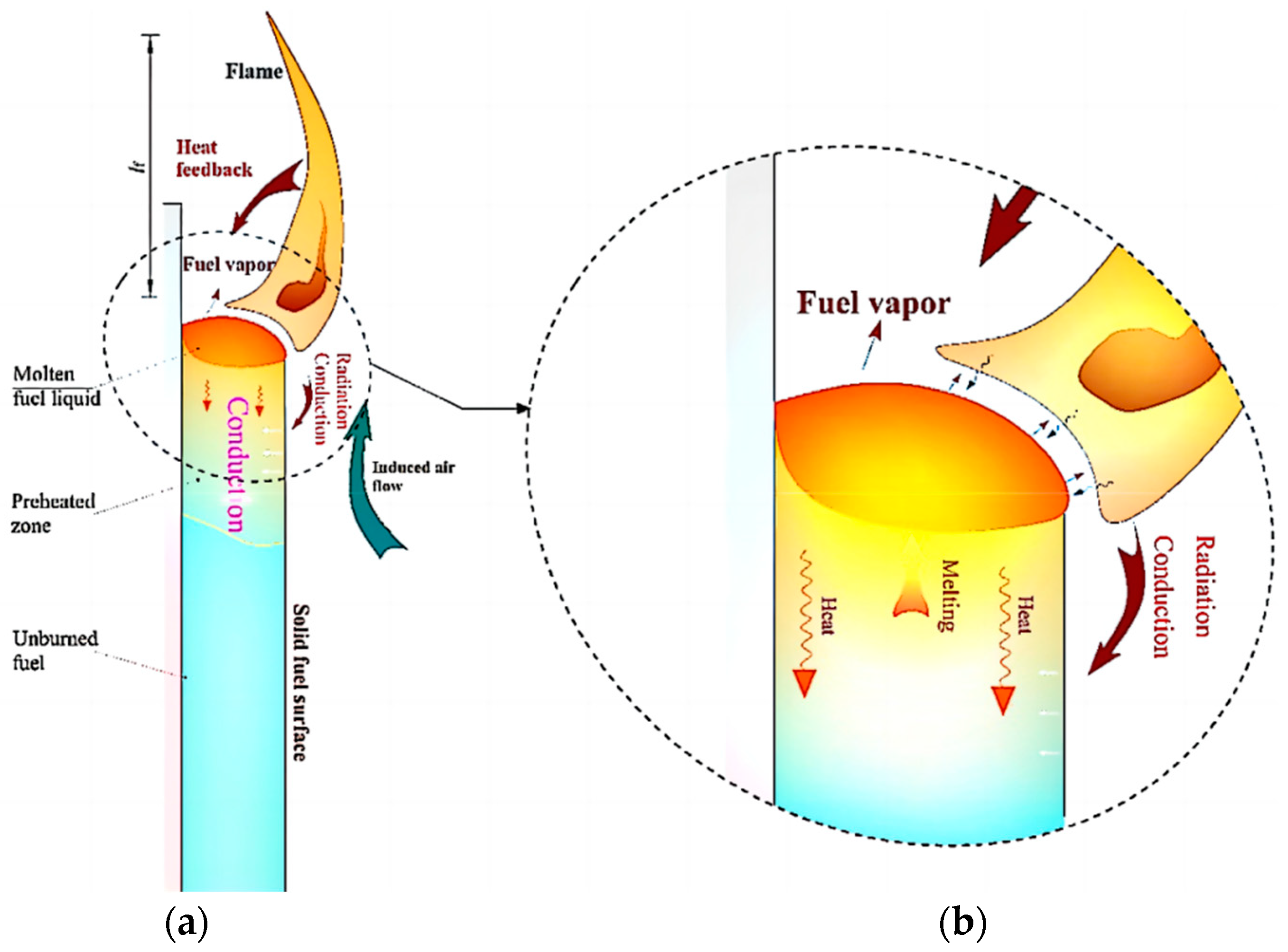
Figure 1. (a) An illustration of the mass and heat transfer for XPS’s flame downward spread; (b) the little pool fire caused by the development of a layer of melting liquid on the surface of the vertical-oriented XPS [63].
Fire 06 00125 g001
Figure 2. The combustion and flame spread of thermoplastic materials.
Fire 06 00125 g002
Figure 3. The model’s schematic: (a) fuel content within the layer; (b) layer thickness of the layer [46].
Fire 06 00125 g003
Figure 4. Three phases of the transient flame spread [59].
Fire 06 00125 g004
Figure 5. Sample heat transfer progress under rising heat flux [56].
Fire 06 00125 g005
Figure 6. (a) asymptotic behavior of ignition time and (b) for smoldering and flaming samples [60].
Fire 06 00125 g006aFire 06 00125 g006b
Figure 7. Stage I: combustion with no dripping; Stage II: dripping with no flame; Stage III: burning and dripping; Stage IV: formation of pool flame [15].
Fire 06 00125 g007
Figure 8. Averaged number of fuel drop drips in each section of 10 cm with (a) increased spacing and (b) various pressures [2].
Fire 06 00125 g008
Figure 9. The average burning rate constant for the PE droplets microgravity burning [108].
Fire 06 00125 g009
Figure 10. The local MBR along the central axis as a consequence of the separation from the sharp end for all slab thicknesses [114].
Fire 06 00125 g010
Figure 11. Change of the local MBR on methanol and ethanol [115].
Fire 06 00125 g011
Figure 12. Experimental arrangement for Moire deflectometry [89].
Fire 06 00125 g012
Figure 13. Surface temperature distributions measured by thermography [127].
Fire 06 00125 g013
Figure 14. NS solutions for temperature (grayscale) and heat release rate (solid line) contours [128].
Fire 06 00125 g014
Figure 15. Axial temperature in the plume region at tilt angles of (a) 30° and (b) 60° [29].
Fire 06 00125 g015aFire 06 00125 g015b
Figure 16. The concurrent floor and ceiling flame spread models [98].
Fire 06 00125 g016
Figure 17. Concurrent-flow flame spread and definition of flame length [151].
Fire 06 00125 g017
Figure 18. Relationship between y O 2 and V g [158].
Fire 06 00125 g018
Figure 19. Flame images for a 24.5 mm sample [159].
Fire 06 00125 g019
Figure 20. Computational flame shapes and experimental flame shapes [161].
Fire 06 00125 g020
Figure 21. Experimental apparatus [162].
Fire 06 00125 g021
Figure 22. Planform of air entrainment variations under varying widths with (a) or without (b) Sides [32].
Fire 06 00125 g022
Figure 23. A physical representation of the ascending flame with a concave shape on PS (a) flat structures, (b) U-shaped structures [33].
Fire 06 00125 g023
Figure 24. Relationship between MLR and sample geometry [17].
Fire 06 00125 g024
Disclaimer/Publisher’s Note: The statements, opinions and data contained in all publications are solely those of the individual author(s) and contributor(s) and not of MDPI and/or the editor(s). MDPI and/or the editor(s) disclaim responsibility for any injury to people or property resulting from any ideas, methods, instructions or products referred to in the content.