
Experimental Investigation on Fire Smoke Temperature under Forced Ventilation Conditions in a Bifurcated Tunnel with Fires Situated in a Branch Tunnel


Abstract
:1. Introduction
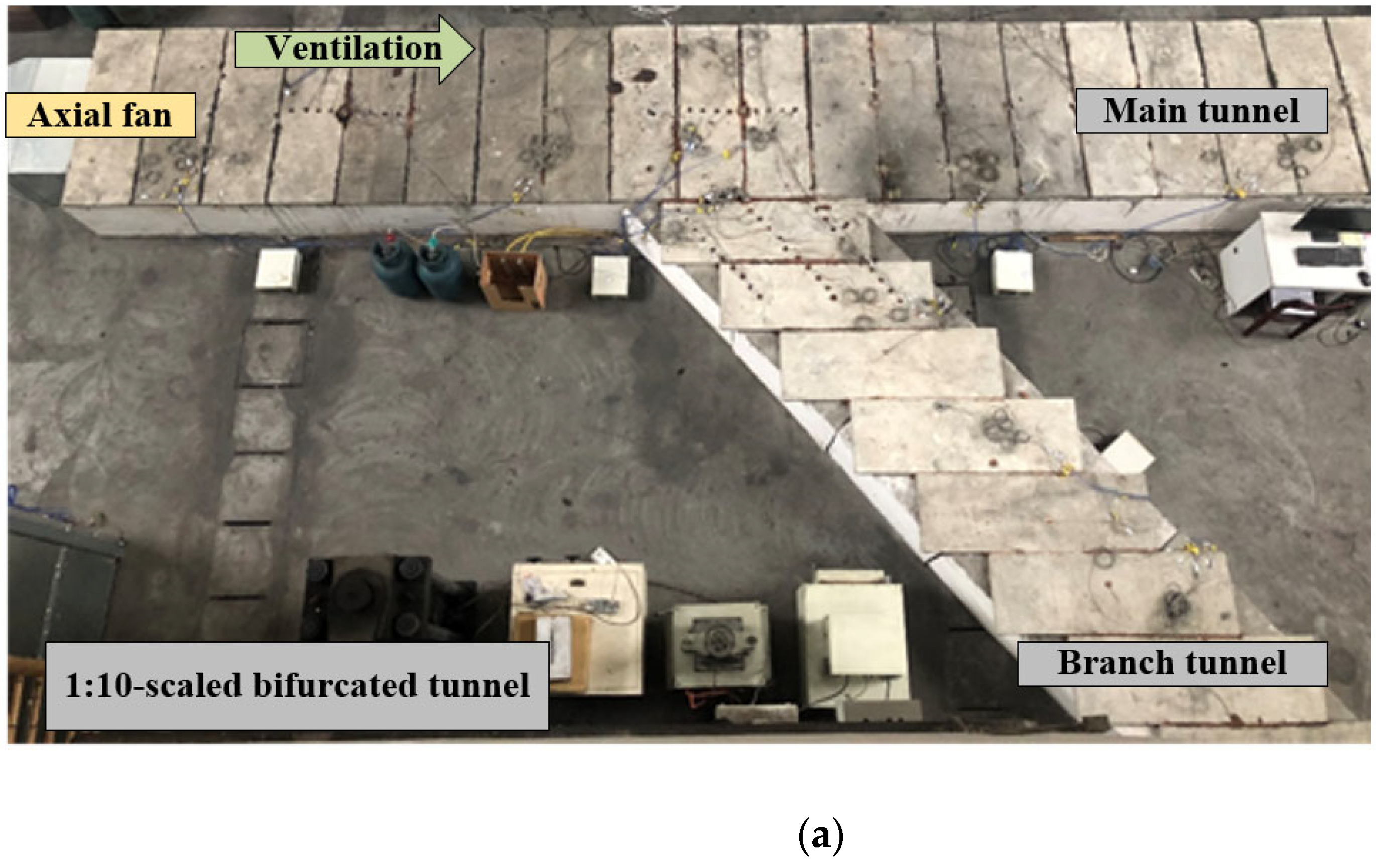
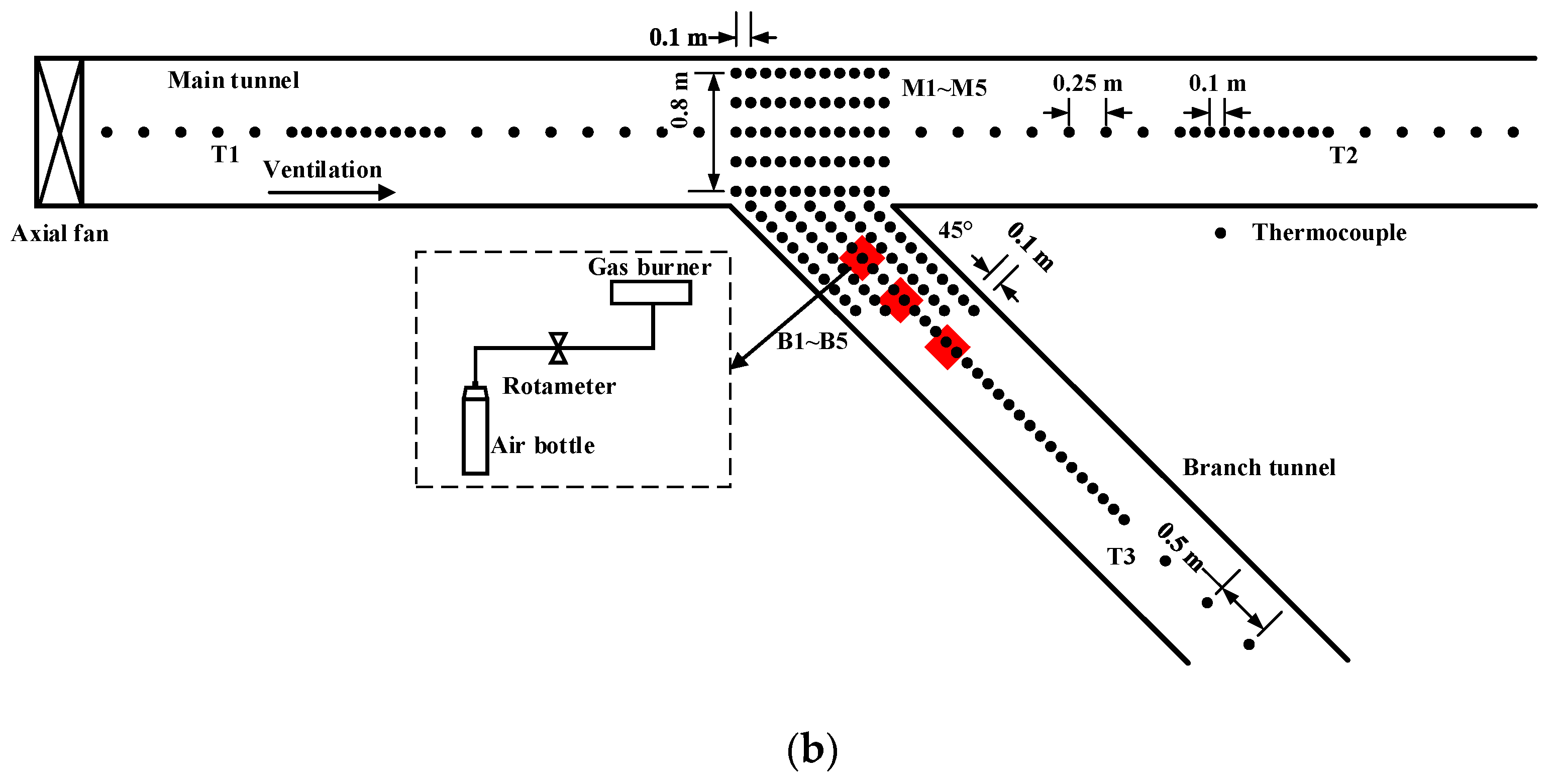
2. Experiment Setup
3. Results and Discussion
3.1. Summary of the Results of the Experiment
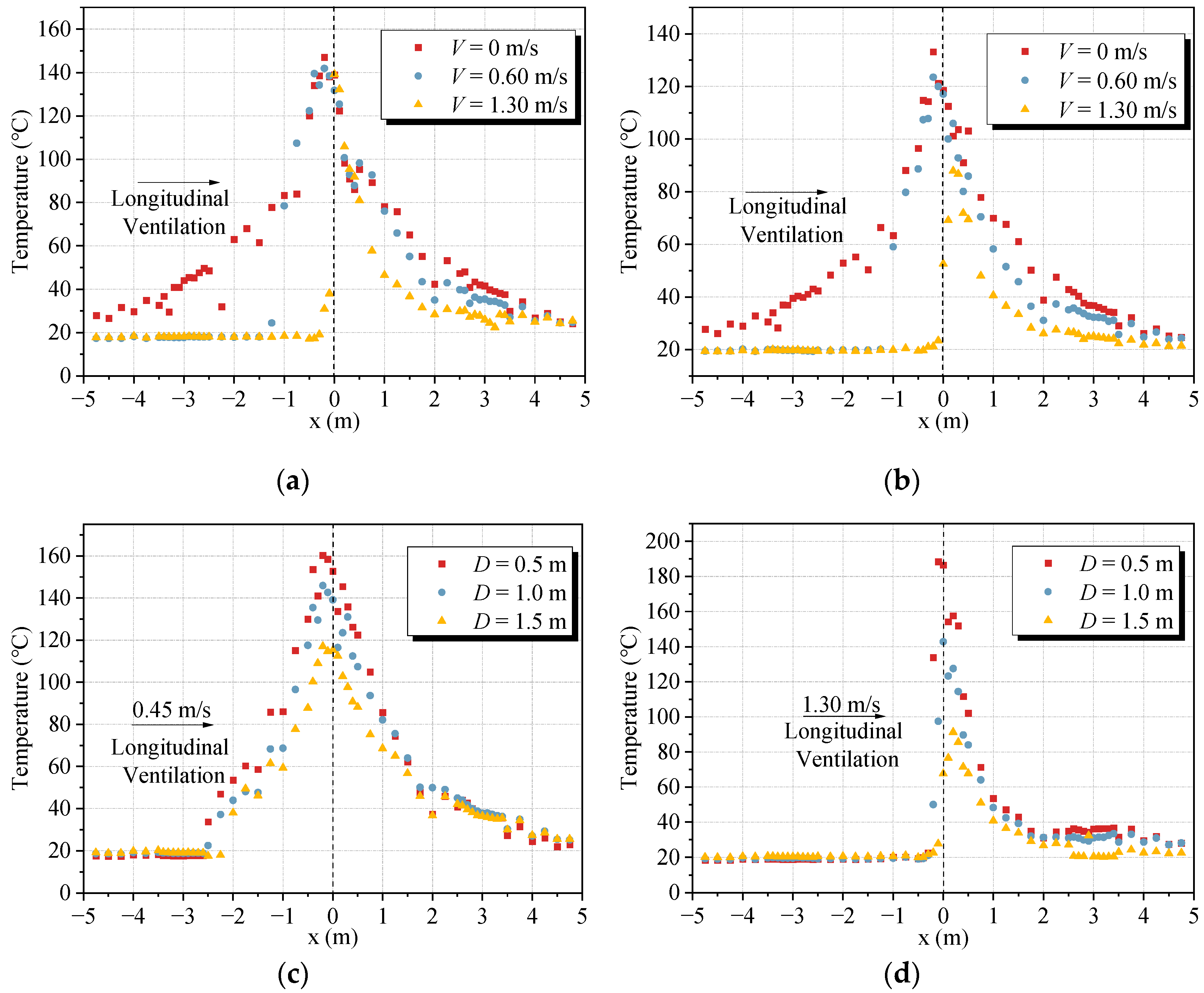
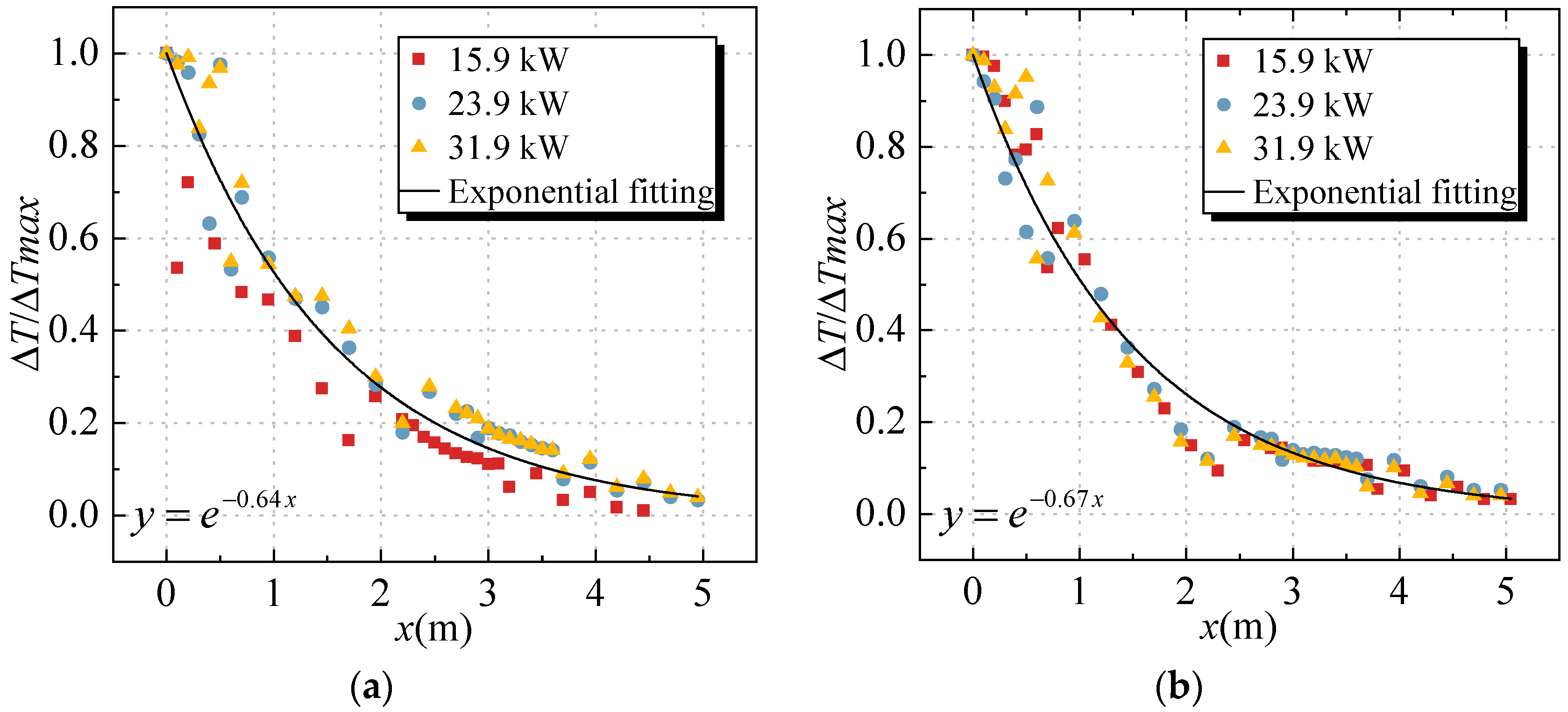
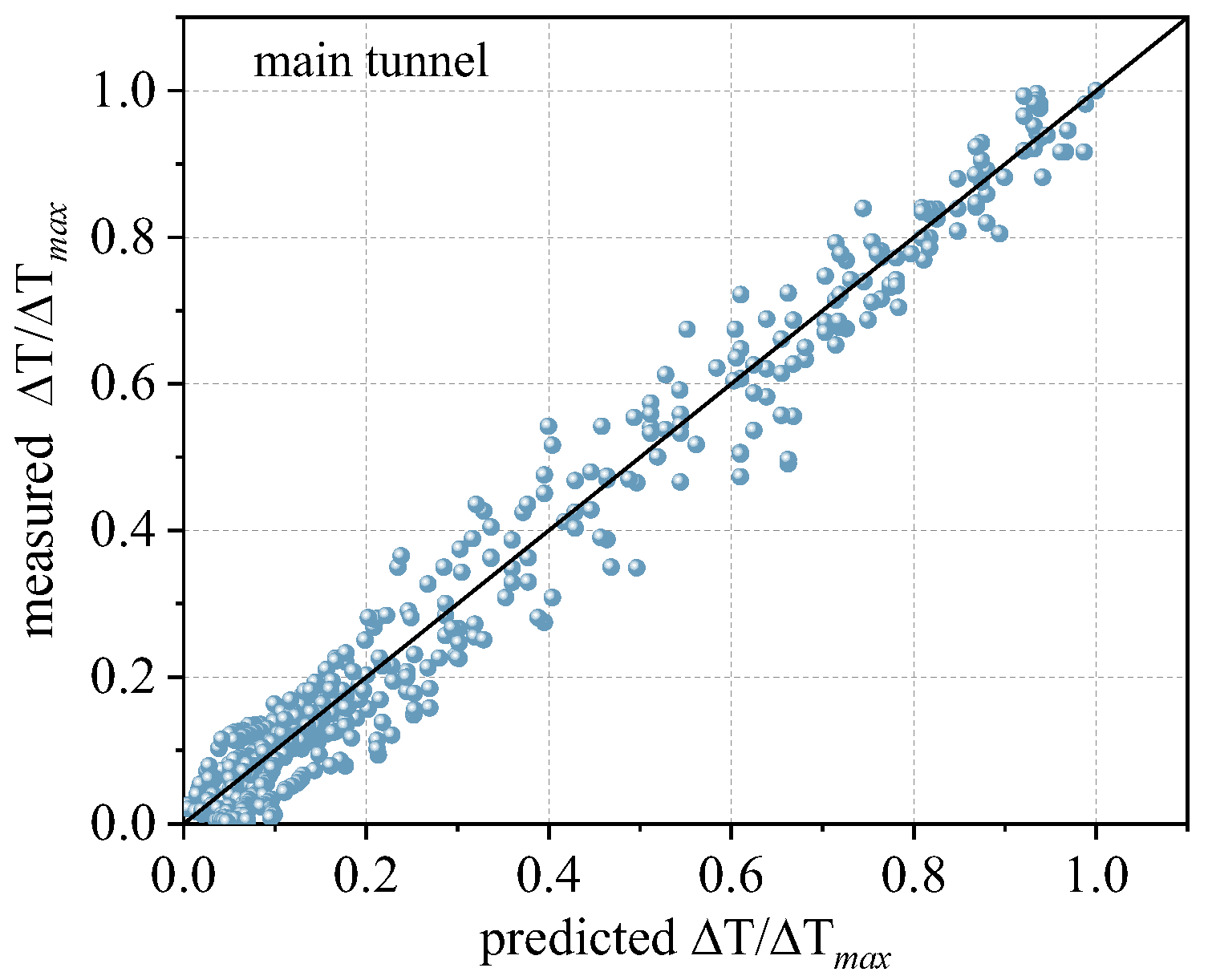
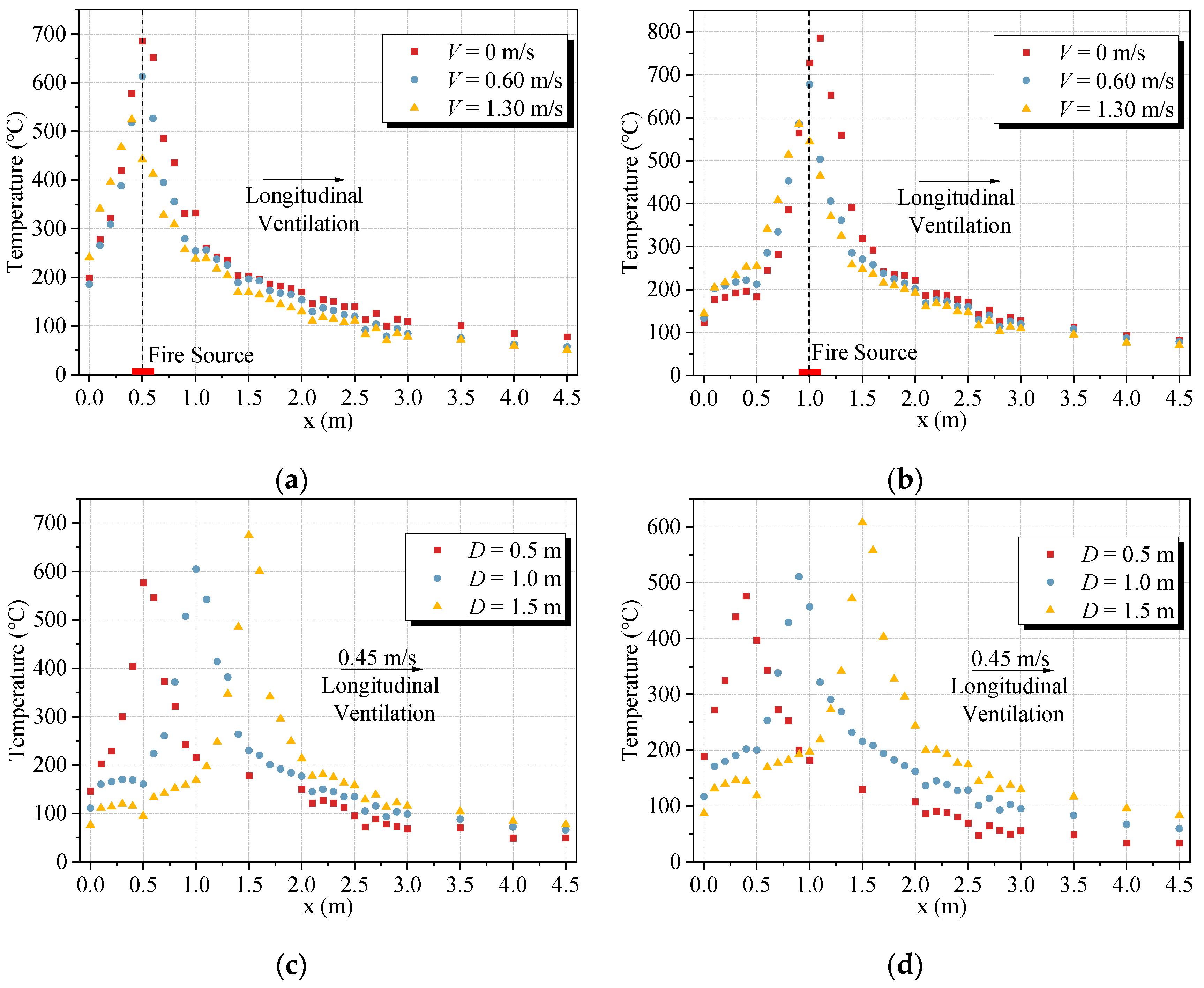
3.2. Smoke Temperature profile in a Main Tunnel
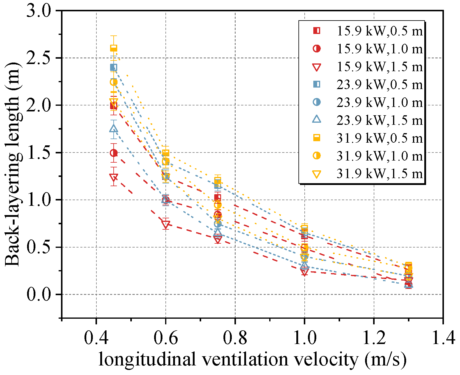
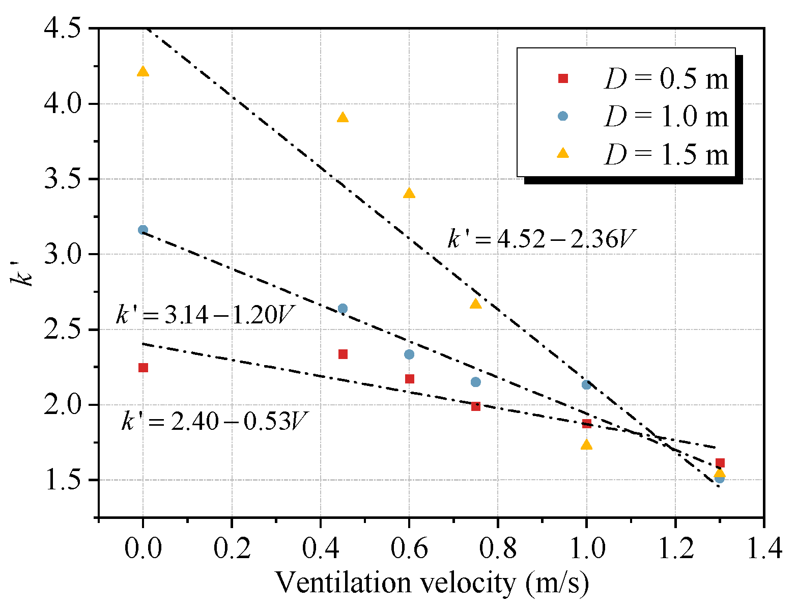
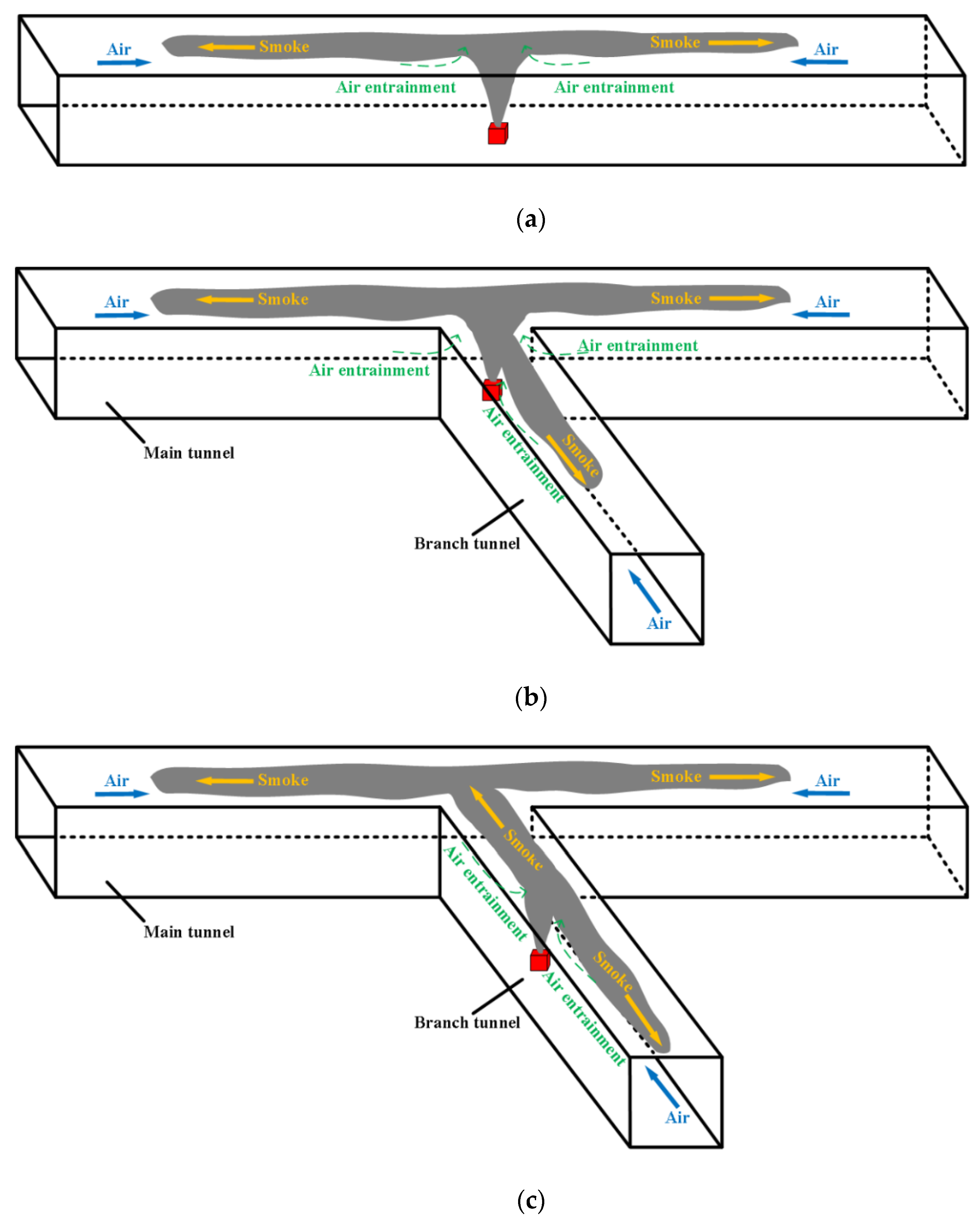
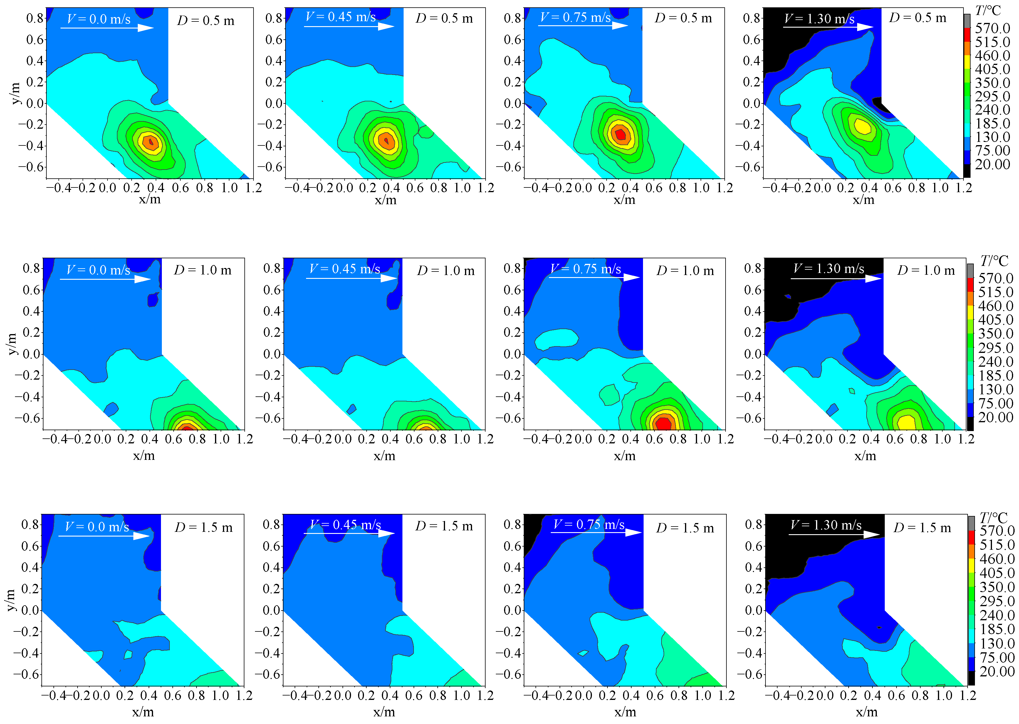
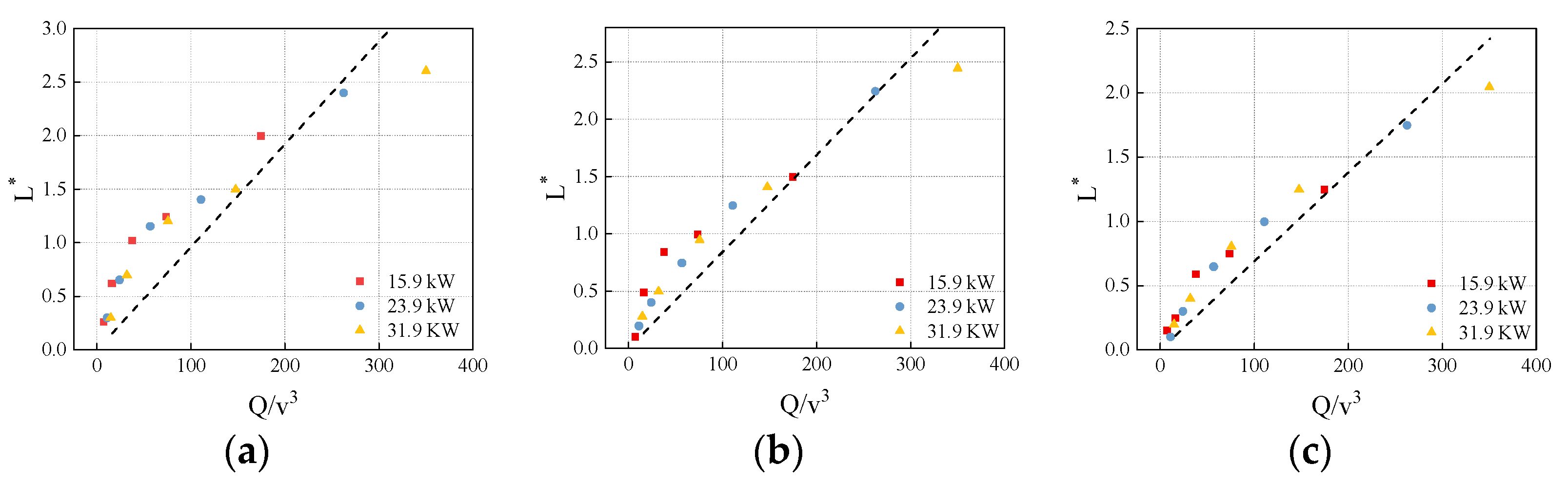
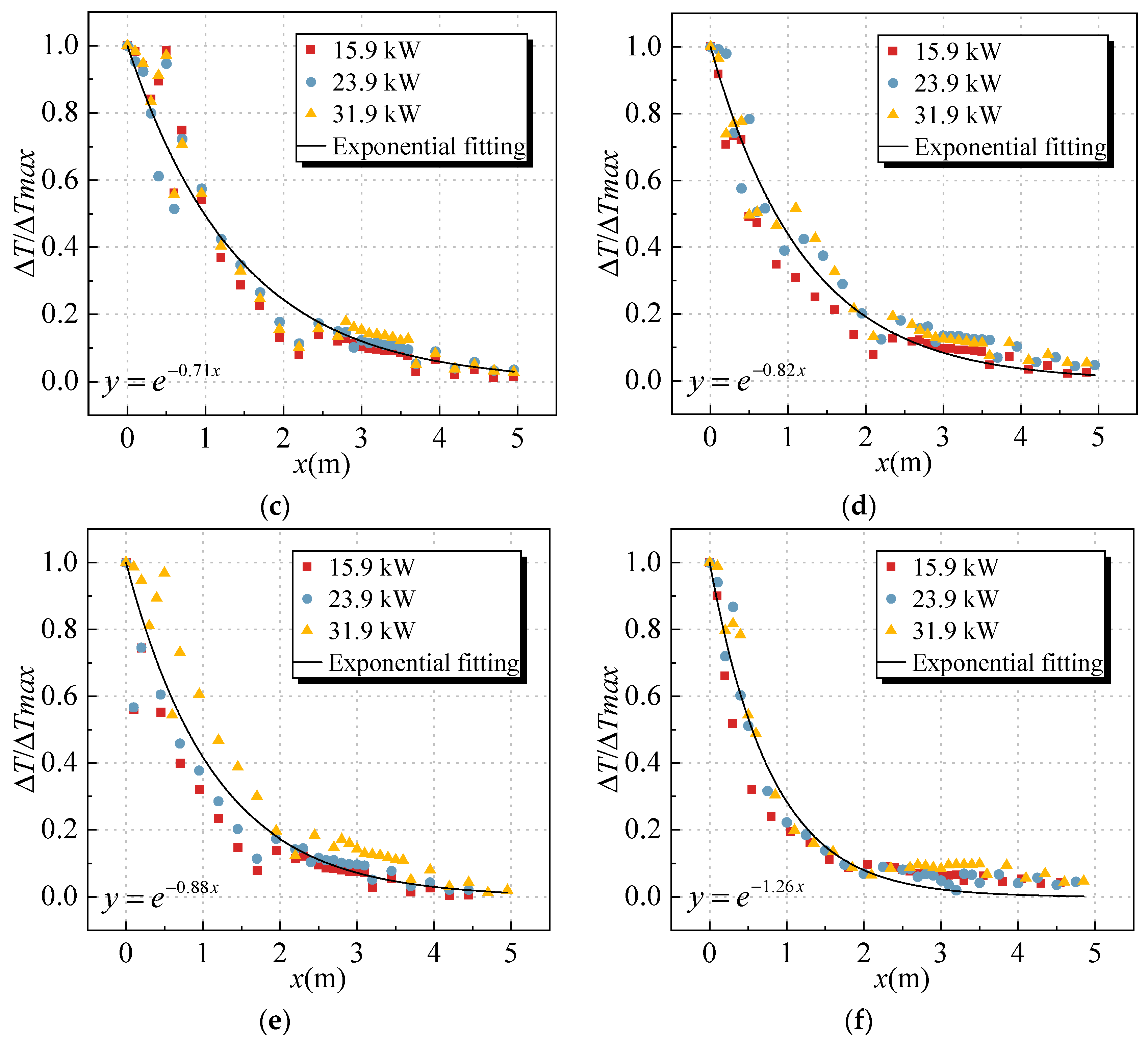
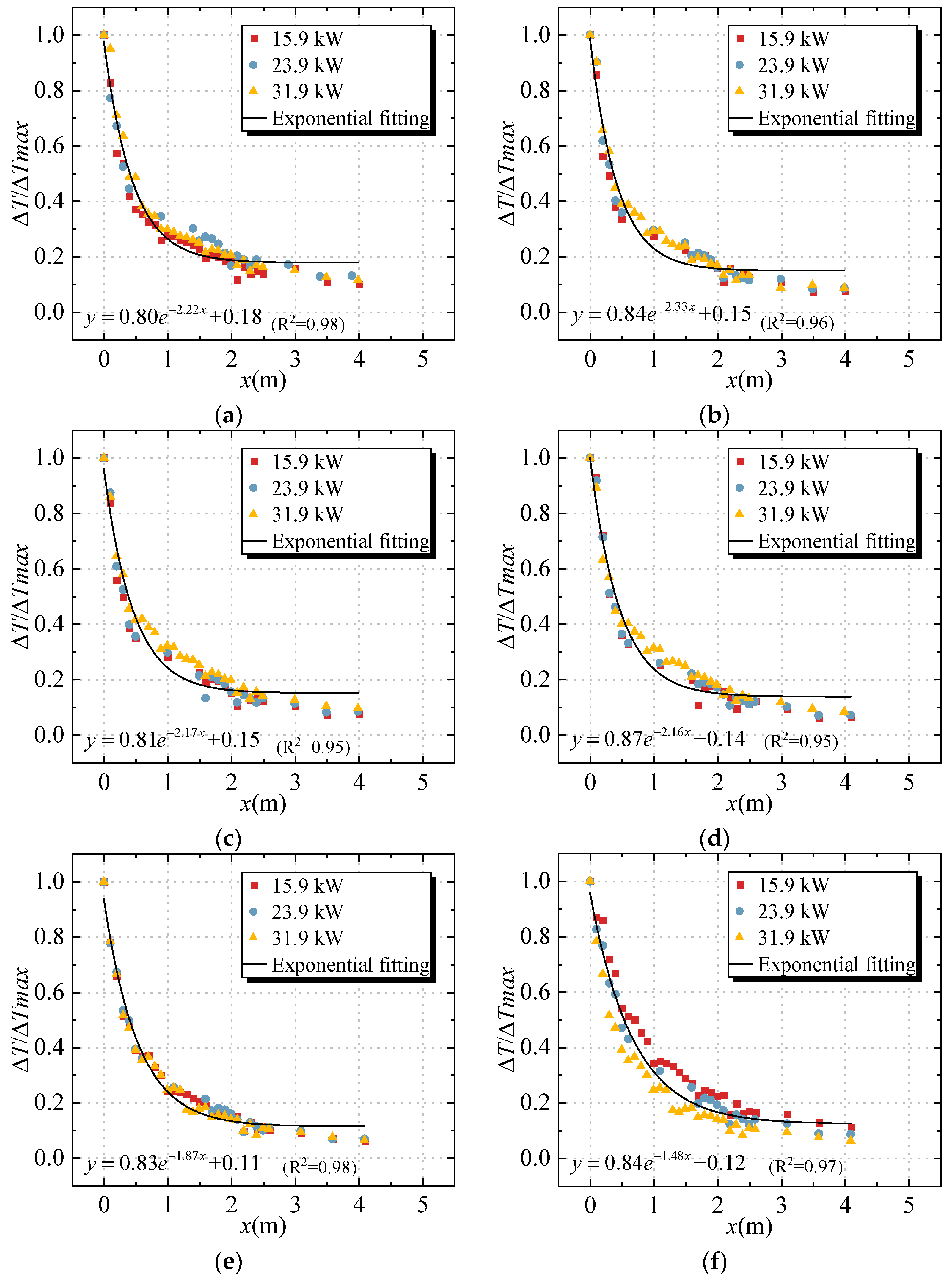
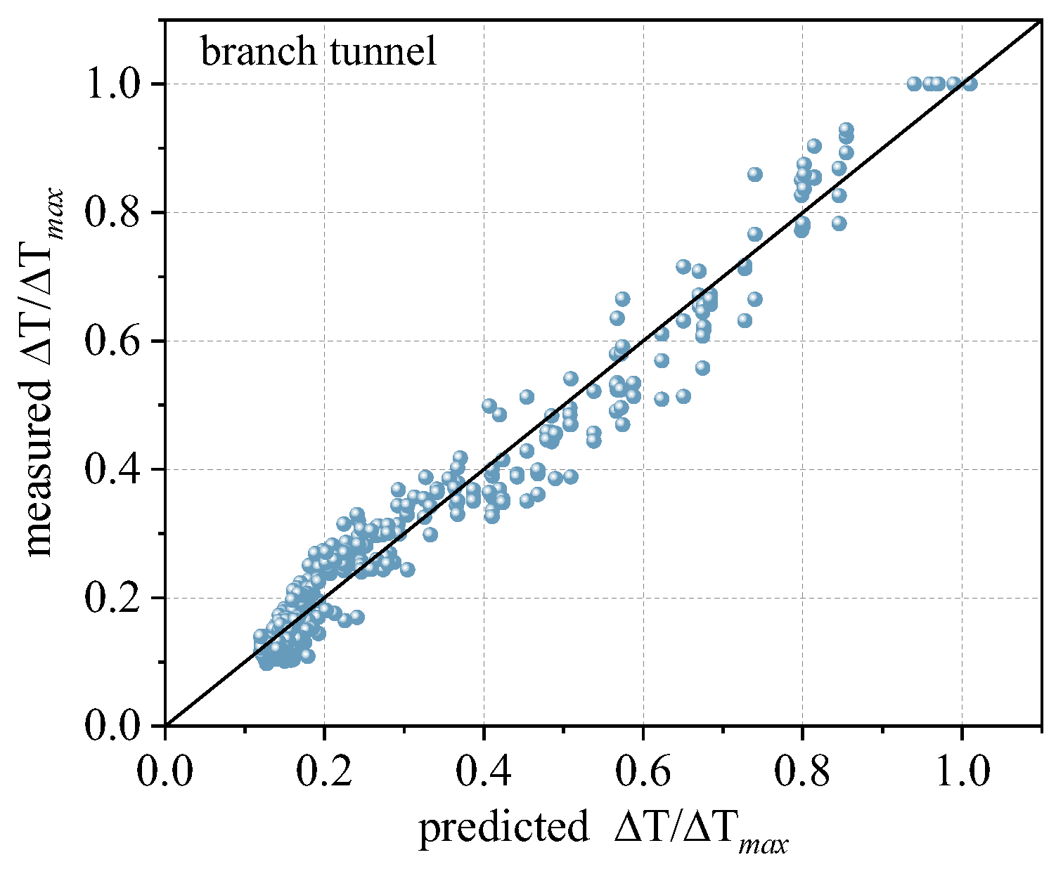
3.3. Smoke Temperature Profile in a Branch Tunnel
4. Conclusions
Author Contributions
Funding
Data Availability Statement
Conflicts of Interest
References
- Vuilleumier, F.; Weatherill, A.; Crausaz, B. Safety aspects of railway and road tunnel: Example of the Lötschberg railway tunnel and Mont-Blanc road tunnel. Tunn. Undergr. Space Technol. 2002, 17, 153–158. [Google Scholar] [CrossRef]
- Lei, P.; Chen, C.; Zhang, Y.; Xu, T.; Sun, H. Experimental study on temperature profile in a branched tunnel fire under natural ventilation considering different fire locations. Int. J. Therm. Sci. 2021, 159, 106631. [Google Scholar] [CrossRef]
- Alpert, R.L. Turbulent Ceiling-Jet Induced by Large-Scale Fires. Combust. Sci. Technol. 1975, 11, 197–213. [Google Scholar] [CrossRef]
- Ji, J.; Fan, C.; Zhong, W.; Shen, X.; Sun, J. Experimental investigation on influence of different transverse fire locations on maximum smoke temperature under the tunnel ceiling. Int. J. Heat Mass Transf. 2012, 55, 4817–4826. [Google Scholar] [CrossRef]
- Fan, C.; Ji, J.; Gao, Z.; Sun, J. Experimental study on transverse smoke temperature distribution in road tunnel fires. Tunn. Undergr. Space Technol. 2013, 37, 89–95. [Google Scholar] [CrossRef]
- Delichatsios, M.A. The flow of fire gases under a beamed ceiling. Combust. Flame 1981, 43, 1–10. [Google Scholar] [CrossRef]
- Hu, L.; Huo, R.; Wang, H.; Li, Y.; Yang, R. Experimental studies on fire-induced buoyant smoke temperature distribution along tunnel ceiling. J. Affect. Disord. 2007, 42, 3905–3915. [Google Scholar] [CrossRef]
- Li, Y.Z.; Lei, B.; Ingason, H. The maximum temperature of buoyancy-driven smoke flow beneath the ceiling in tunnel fires. Fire Saf. J. 2011, 46, 204–210. [Google Scholar] [CrossRef]
- Hu, L.; Chen, L.; Wu, L.; Li, Y.; Zhang, J.; Meng, N. An experimental investigation and correlation on buoyant gas temperature below ceiling in a slopping tunnel fire. Appl. Therm. Eng. 2013, 51, 246–254. [Google Scholar] [CrossRef]
- Hu, L.; Huo, R.; Peng, W.; Chow, W.; Yang, R. On the maximum smoke temperature under the ceiling in tunnel fires. Tunn. Undergr. Space Technol. 2006, 21, 650–655. [Google Scholar] [CrossRef]
- Hu, L.; Huo, R.; Chow, W. Studies on buoyancy-driven back-layering flow in tunnel fires. Exp. Therm. Fluid Sci. 2008, 32, 1468–1483. [Google Scholar] [CrossRef]
- Bai, Z.P.; Li, Y.F. Effect of Longitudinal Ventilation on Smoke Temperature below Utility Tunnel Ceiling. Eng. Lett. 2020, 28, 939–943. [Google Scholar]
- Zhao, S.; Liu, F.; Wang, F.; Weng, M. Experimental studies on fire-induced temperature distribution below ceiling in a longitudinal ventilated metro tunnel. Tunn. Undergr. Space Technol. 2018, 72, 281–293. [Google Scholar] [CrossRef]
- Chen, C.-K.; Zhu, C.-X.; Liu, X.-Y.; Yu, N.-H. Experimental investigation on the effect of asymmetrical sealing on tunnel fire behavior. Int. J. Heat Mass Transf. 2016, 92, 55–65. [Google Scholar] [CrossRef]
- Huang, Y.; Li, Y.; Dong, B.; Li, J.; Liang, Q. Numerical investigation on the maximum ceiling temperature and longitudinal decay in a sealing tunnel fire. Tunn. Undergr. Space Technol. 2018, 72, 120–130. [Google Scholar] [CrossRef]
- Li, J.; Li, Y.; Li, J.; Yang, Q. Numerical investigation on the smoke behaviour and longitudinal temperature decay in tilted tunnel fire with portal sealing. Indoor Built Environ. 2023, 32, 133–148. [Google Scholar] [CrossRef]
- Yuan, Z.Y.; Lei, B.; Bi, H.Q. The Effect of Fire Location on Smoke Temperature in Tunnel Fires with Natural Ventilation. Procedia Eng. 2015, 121, 2119–2124. [Google Scholar] [CrossRef]
- Haddad, R.K.; Zulkifli, R.; Maluk, C.; Harun, Z. Experimental Investigation on the Influences of Different Horizontal Fire Locations on Smoke Temperature Stratification under Tunnel Ceiling. J. Appl. Fluid Mech. 2020, 13, 1289–1298. [Google Scholar]
- Cong, W.; Shi, L.; Shi, Z.; Peng, M.; Yang, H.; Zhang, S.; Cheng, X. Effect of train fire location on maximum smoke temperature beneath the subway tunnel ceiling. Tunn. Undergr. Space Technol. 2020, 97, 103282. [Google Scholar] [CrossRef]
- Sturm, P.; Fößleitner, P.; Fruhwirt, D.; Galler, R.; Wenighofer, R.; Heindl, S.F.; Krausbar, S.; Heger, O. Fire tests with lithium-ion battery electric vehicles in road tunnels. Fire Saf. J. 2022, 134, 103695. [Google Scholar] [CrossRef]
- Álvarez-Coedo, D.; Ayala, P.; Cantizano, A.; Węgrzyński, W. A coupled hybrid numerical study of tunnel longitudinal ventilation under fire conditions. Case Stud. Therm. Eng. 2022, 36, 102202. [Google Scholar] [CrossRef]
- Galhardo, A.; Viegas, J.; Coelho, P.J. The influence of wind on smoke propagation to the lower layer in naturally ventilated tunnels. Tunn. Undergr. Space Technol. 2022, 128, 104632. [Google Scholar] [CrossRef]
- Li, Q.; Chen, C. Survey and measurement of the vehicle pollutant emission in urban underground bifurcate tunnel, China. Sustain. Cities Soc. 2019, 48, 101519. [Google Scholar] [CrossRef]
- Li, Q.; Chen, C.; Yuan, H.; Wang, L.; Xu, S.; Li, Y. Prediction of pollutant concentration and ventilation control in urban bifurcate tunnel, China. Tunn. Undergr. Space Technol. 2018, 82, 406–415. [Google Scholar] [CrossRef]
- Liu, C.; Zhong, M.; Tian, X.; Zhang, P.; Xiao, Y.; Mei, Q. Experimental and numerical study on fire-induced smoke temperature in connected area of metro tunnel under natural ventilation. Int. J. Therm. Sci. 2019, 138, 84–97. [Google Scholar] [CrossRef]
- Tang, F.; Li, L.; Chen, W.; Tao, C.; Zhan, Z. Studies on ceiling maximum thermal smoke temperature and longitudinal decay in a tunnel fire with different transverse gas burner locations. Appl. Therm. Eng. 2017, 110, 1674–1681. [Google Scholar] [CrossRef]
- Li, L.; Li, S.; Wang, X.; Zhang, H. Fire-induced flow temperature along tunnels with longitudinal ventilation. Tunn. Undergr. Space Technol. 2012, 32, 44–51. [Google Scholar] [CrossRef]
- Chen, L.F.; Hu, L.H.; Zhang, X.L.; Zhang, X.Z.; Zhang, X.C.; Yang, L.Z. Thermal buoyant smoke back-layering flow length in a longitudinal ventilated tunnel with ceiling extraction at difference distance from heat source. Appl. Therm. Eng. 2015, 78, 129–135. [Google Scholar] [CrossRef]
- Chen, L.; Hu, L.; Tang, W.; Yi, L. Studies on buoyancy driven two-directional smoke flow layering length with combination of point extraction and longitudinal ventilation in tunnel fires. Fire Saf. J. 2013, 59, 94–101. [Google Scholar] [CrossRef]
- Thomas, P.H. The Movement of Smoke in Horizontal Passages against Air Flow. Fire Saf. Sci. 1968, 7, 1–8. [Google Scholar]
- Zhong, W.; Li, Z.; Wang, T.; Liang, T.; Liu, Z. Experimental Study on the Influence of Different Transverse Fire Locations on the Critical Longitudinal Ventilation Velocity in Tunnel Fires. Fire Technol. 2015, 51, 1217–1230. [Google Scholar] [CrossRef]
- Kurioka, H.; Oka, Y.; Satoh, H.; Sugawa, O. Fire properties in near field of square fire source with longitudinal ventilation in tunnels. Fire Saf. J. 2003, 38, 319–340. [Google Scholar] [CrossRef]
- Wu, Y.; Bakar, M. Control of smoke flow in tunnel fires using longitudinal ventilation systems—A study of the critical velocity. Fire Saf. J. 2000, 35, 363–390. [Google Scholar] [CrossRef]
- Lei, P.; Chen, C.; Jiao, W.; Shi, C. Experimental study on collaborative longitudinal ventilation of smoke control for branched tunnel fires considering different branch angles. Tunn. Undergr. Space Technol. 2023, 136, 105097. [Google Scholar] [CrossRef]
- Chen, L.; Zhou, S.; Lan, Y.; Liu, X.; Yang, Y.; Li, X.; Yan, X.; Chen, H. Experimental study on fire characteristics of the bifurcated tunnel under multi-directional ventilation. Int. J. Therm. Sci. 2023, 185, 108072. [Google Scholar] [CrossRef]
- Tao, H.; Xu, Z.; Zhang, Y.; Zhang, X.; Fan, C. An experimental study on the smoke spread in underground interconnected infrastructure with longitudinal ventilation. Tunn. Undergr. Space Technol. 2023, 142, 105381. [Google Scholar] [CrossRef]
- Chen, C.; Nie, Y.; Zhang, Y.; Lei, P.; Fan, C.; Wang, Z. Experimental investigation on the influence of ramp slope on fire behaviors in a bifurcated tunnel. Tunn. Undergr. Space Technol. 2020, 104, 103522. [Google Scholar] [CrossRef]
- Chen, C.; Zhang, Y.; Lei, P.; Zeng, W.; Jiao, W. Experimental study on fire behaviors in narrow bifurcated channel with a confined portal. Combust. Sci. Technol. 2020, 193, 2194–2216. [Google Scholar] [CrossRef]
- Liu, C.; Zhong, M.; Shi, C.; Zhang, P.; Tian, X. Temperature profile of fire-induced smoke in node area of a full-scale mine shaft tunnel under natural ventilation. Appl. Therm. Eng. 2017, 110, 382–389. [Google Scholar] [CrossRef]
- Li, Z.; Gao, Y.; Li, X.; Mao, P.; Zhang, Y.; Jin, K.; Li, T.; Chen, L. Effects of transverse fire locations on flame length and temperature distribution in a bifurcated tunnel fire. Tunn. Undergr. Space Technol. 2021, 112, 103893. [Google Scholar] [CrossRef]
- Chen, L.; Mao, P.; Zhang, Y.; Xing, S.; Li, T. Experimental study on smoke characteristics of bifurcated tunnel fire. Tunn. Undergr. Space Technol. 2020, 98, 103295. [Google Scholar] [CrossRef]
- Huang, Y.; Li, Y.; Li, J.; Li, J.; Wu, K.; Zhu, K.; Li, H. Experimental investigation on maximum gas temperature beneath the ceiling in a branched tunnel fire. Int. J. Therm. Sci. 2019, 145, 105997. [Google Scholar] [CrossRef]
- Yang, X.; Luo, Y.; Li, Z.; Guo, H.; Zhang, Y. Experimental investigation on the smoke back-layering length in a branched tunnel fire considering different longitudinal ventilations and fire locations. Case Stud. Therm. Eng. 2021, 28, 101497. [Google Scholar] [CrossRef]
- Li, Y.Z.; Ingason, H. Model scale tunnel fire tests with automatic sprinkler. Fire Saf. J. 2013, 61, 298–313. [Google Scholar] [CrossRef]
- Li, Y.Z.; Lei, B.; Ingason, H. Study of critical velocity and backlayering length in longitudinally ventilated tunnel fires. Fire Saf. J. 2010, 45, 361–370. [Google Scholar] [CrossRef]
- Ho, C.L.; Li, K.Y.; Spearpoint, M.J. Numerical simulation of scale-model smoke contamination of upper atrium levels by a channelled balcony spill plume. Fire Mater. 2012, 37, 581–596. [Google Scholar] [CrossRef]
- Thomas, P. The movement of buoyant fluid against a stream and the venting of underground fires. Fire Saf. Sci. 1958, 351, 1. [Google Scholar]
- Evers, E.; Waterhouse, A. A complete model for analyzing smoke movement in building. In Building Research Establishment; BRE CP: Borehamwood/Hertfordshire, England, 1981; Volume 69. [Google Scholar]
- Hu, L.H.; Huo, R.; Li, Y.Z.; Wang, H.B.; Chow, W.K. Full-scale burning tests on studying smoke temperature and velocity along a corridor. Tunn. Undergr. Space Technol. 2005, 20, 223–229. [Google Scholar] [CrossRef]


| Test No. | HRR (kW) | D (m) | V (ms−1) |
|---|---|---|---|
| 1–18 | |||
| 19–36 | |||
| 37–54 |
| Fire Location D (m) | ||||||
|---|---|---|---|---|---|---|
| 0.00 | 0.45 | 0.60 | 0.75 | 1.00 | 1.30 | |
| 0.5 | 0.64 | 0.67 | 0.71 | 0.82 | 0.88 | 1.26 |
| 1.0 | 0.62 | 0.70 | 0.73 | 0.84 | 1.05 | 1.17 |
| 1.5 | 0.70 | 0.73 | 0.75 | 0.84 | 0.90 | 1.18 |
| V | |||||||||
|---|---|---|---|---|---|---|---|---|---|
| a | b | k | a | b | k | a | b | k | |
| 0.0 | 0.80 | 0.16 | 2.25 | 0.81 | 0.17 | 3.16 | 0.82 | 0.19 | 4.21 |
| 0.45 | 0.84 | 0.15 | 2.34 | 0.85 | 0.16 | 2.64 | 0.84 | 0.17 | 3.90 |
| 0.60 | 0.81 | 0.15 | 2.17 | 0.82 | 0.17 | 2.33 | 0.80 | 0.18 | 3.40 |
| 0.75 | 0.86 | 0.15 | 1.99 | 0.85 | 0.17 | 2.15 | 0.76 | 0.19 | 2.66 |
| 1.00 | 0.82 | 0.12 | 1.87 | 0.84 | 0.16 | 2.13 | 0.76 | 0.19 | 1.73 |
| 1.30 | 0.83 | 0.14 | 1.62 | 0.85 | 0.17 | 1.51 | 0.75 | 0.20 | 1.54 |
| Average | 0.83 | 0.15 | ✕ | 0.84 | 0.17 | ✕ | 0.78 | 0.19 | ✕ |
Disclaimer/Publisher’s Note: The statements, opinions and data contained in all publications are solely those of the individual author(s) and contributor(s) and not of MDPI and/or the editor(s). MDPI and/or the editor(s) disclaim responsibility for any injury to people or property resulting from any ideas, methods, instructions or products referred to in the content. |
© 2023 by the authors. Licensee MDPI, Basel, Switzerland. This article is an open access article distributed under the terms and conditions of the Creative Commons Attribution (CC BY) license (https://creativecommons.org/licenses/by/4.0/).
Share and Cite
Guo, H.; Yang, Z.; Zhang, P.; Gao, Y.; Zhang, Y. Experimental Investigation on Fire Smoke Temperature under Forced Ventilation Conditions in a Bifurcated Tunnel with Fires Situated in a Branch Tunnel. Fire 2023, 6, 473. https://doi.org/10.3390/fire6120473
Guo H, Yang Z, Zhang P, Gao Y, Zhang Y. Experimental Investigation on Fire Smoke Temperature under Forced Ventilation Conditions in a Bifurcated Tunnel with Fires Situated in a Branch Tunnel. Fire. 2023; 6(12):473. https://doi.org/10.3390/fire6120473
Chicago/Turabian StyleGuo, Hanwen, Zhengyuan Yang, Peiyao Zhang, Yunji Gao, and Yuchun Zhang. 2023. "Experimental Investigation on Fire Smoke Temperature under Forced Ventilation Conditions in a Bifurcated Tunnel with Fires Situated in a Branch Tunnel" Fire 6, no. 12: 473. https://doi.org/10.3390/fire6120473
APA StyleGuo, H., Yang, Z., Zhang, P., Gao, Y., & Zhang, Y. (2023). Experimental Investigation on Fire Smoke Temperature under Forced Ventilation Conditions in a Bifurcated Tunnel with Fires Situated in a Branch Tunnel. Fire, 6(12), 473. https://doi.org/10.3390/fire6120473