Article

Optimization of the Monitoring of Coal Spontaneous Combustion Degree Using a Distributed Fiber Optic Temperature Measurement System: Field Application and Evaluation

1
School of Emergency Management and Safety Engineering, China University of Mining & Technology-Beijing, Beijing 100083, China
2
State Key Laboratory of Coal Resources and Safety Mining, China University of Mining & Technology-Beijing, Beijing 100083, China
3
Chongqing Baian Technology Co., Chongqing 400026, China
4
College of Safety and Environmental Engineering, Shandong University of Science and Technology, Qingdao 266590, China
*
Authors to whom correspondence should be addressed.
Fire 2023, 6(11), 410; https://doi.org/10.3390/fire6110410
Submission received: 26 September 2023 / Revised: 19 October 2023 / Accepted: 24 October 2023 / Published: 26 October 2023
(This article belongs to the Special Issue Simulation, Experiment and Modeling of Coal Fires)

Abstract

:
Coal spontaneous combustion (CSC) in gob not only leads to wasted resources and casualties, but also produces a lot of waste gas that pollutes the underground environment. Mastering the degree of CSC helps ensure that timely and effective control measures are taken. The real-time and accurate monitoring of temperature, as the primary indicator of the extent of CSC, is difficult due to the harsh and hidden environment of gob, resulting in a reduced ability to anticipate and prevent CSC. In this work, a complete distributed optical fiber temperature sensing system (DTSS) set with strong anti-damage ability was developed. The optical cable is protected by internal parallel steel cables and external protective pipes, which greatly improve the system’s reliability and integrity when used in gob. During its application in the Wangyun Coal Mine, an abnormal temperature rise in gob was discovered in time, and the effect of inhibitor spraying was monitored and evaluated. The degree of CSC in the gob was accurately identified, which shows that the work of coal mining can be targeted. This work is expected to improve early warning capability to prevent the risk of CSC in gob, and has promising applications.

1. Introduction

As a major fossil energy source, a small portion of coal is inevitably left in gob due to the limitations of mining technology [1,2]. The residual coal undergoes oxidation and gradually releases heat under the coupling effect of multiple physical fields [3,4]. The continuous accumulation of heat can easily lead to the occurrence of coal spontaneous combustion (CSC), which is difficult to extinguish in a short period of time [5,6]. CSC gravely threatens the safety of coal production and the safety of workers [7,8]. It not only leads to a large amount of wasted coal resources [9], but also destroys the underground geological and ecological environment [10]. When certain conditions are met, it may even cause secondary disasters such as gas explosions, thus causing large-scale casualties [11,12,13]. Therefore, corresponding measures must be taken to prevent the occurrence of CSC disasters in gob [14].
In order to implement targeted governance measures, it is particularly vital to grasp the degree of CSC in gob [15,16]. The main characteristics of CSC include rising temperature and the generation of gases such as alkane [17]. And CO is usually used as the main iconic gas for the early warning and prediction of CSC in gob [18,19]. The mapping relationship between iconic gases and the degree of CSC is generally determined through mathematical models established in the laboratory [20,21]. However, applying this mapping relationship in large-sized gob may raise doubts about the accuracy of the model due to numerous uncertain factors [22], and iconic gases are the products of a coal oxidation reaction, so it exhibits hysteresis when predicting CSC in gob [23]. Given that the direct effect of the oxidized exotherm of the coal body is to cause an increase in temperature, it is feasible and reasonable to use temperature indicators to anticipate CSC.
Due to the concealment and complexity of gob [24], the selection of temperature monitoring technology should be comprehensively considered from various aspects, such as the accuracy, continuity, stability, and intuitiveness of data results. The current commonly used probe-based temperature measurement method is point-of-contact, which has the disadvantages of long measurement time, a large workload, and the inability to continuously monitor. Most notably, the probe and cable are easily damaged, and it is not suitable to use it on a large scale [25]. A characteristic of methods such as isotope radon measurement [26] and magnetic and infrared induction [27,28] is that they cannot achieve directly contact in high-temperature locations, which leads the positioning and value of temperature anomaly points to be inaccurate. The radio wave detection method has high accuracy and low cost, but the transmission technology used in gob still needs further improvement [29]. In recent years, fiber optic sensing technology has been widely applied in temperature monitoring and warning in various industrial fields [30,31]. However, the complex underground environment of coal mines places higher demands on the safety performance of equipment. And in the application of coal mine gob with coal/rock caving and mining stress, determining how to prevent the negative effect of perception and the transmission of temperature caused by damage to optical cables is a challenge that hinders the application of optical fiber temperature measurement technology [32].
To address the above issues, herein, a new set of products and technologies are developed that can improve the safety of the temperature measurement method through the design of safety barriers. And a method is designed to improve its damage resistance from the internal and external structures of optical cables, which can ensure the accuracy and continuity of online temperature monitoring in complex environments with gob. This product and technology were successfully applied in the Wangyun Coal Mine in China and greatly improved the monitoring and warning capabilities for CSC hazards in gob.

2. Detection System

2.1. Technical Principle

The technology of distributed optical fiber temperature detection is achieved through Raman scattering [33,34]. Figure 1 shows the technical principle of the distributed optical fiber temperature sensing system (DTSS), which mainly includes a device host, a terminal computer, optical cables for temperature measurement, and a meta-plane of temperature perception.
The device host sends a laser pulse into the optical cable, and the interaction between the laser pulse and the fiber molecules generates Raman-scattered light [35,36]. A small fraction of it is called back-scattered light, which is oriented in the opposite direction to the incident light. The intensity of this back-scattered light has a certain correlation with the temperature of the scattering point in the optical cable. The higher the temperature, the higher the intensity of the back-scattered light. When the back-scattered light signal returns to the device host, it can be converted into a digital signal through demodulation technology and output on the terminal computer to display its temperature and position information. This technique can detect temperature anomalies in a timely manner, which facilitates the implementation of risk prevention measures.

2.2. Demodulation Process

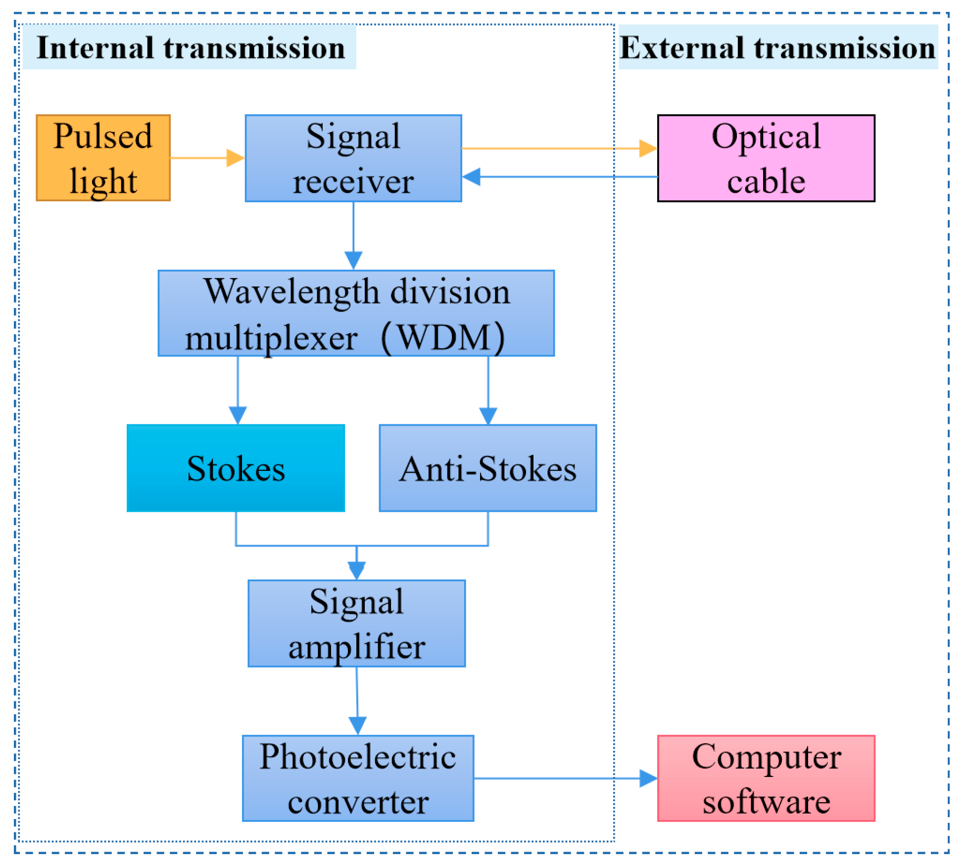
Figure 2 shows the demodulation process of DTSS. The laser pulse is emitted by a laser with a high-power semiconductor. The laser pulse entering the external optical cable generates back-scattered optical signals and transmits them back to the signal receiver. Next, a wavelength division multiplexer (WDM) separates the temperature-insensitive Stokes light and temperature−sensitive anti−Stokes light from the back−scattered light, and amplifies their gain through a signal amplifier. A photoelectric converter demodulates the temperature information carried by the light into electrical signals, and finally, outputs them to an external computer [37,38].
The specific principle of signal demodulation involves the following mathematical formula. The scattering photon frequencies of Stokes and anti−Stokes light are [39,40,41]:
ν s = ν 0 Δ ν
ν a s = ν 0 + Δ ν
where v 0 is the vibrational frequency of the optical fiber molecule, and Δ v is the frequency shift value of Raman scattering, 1.32 × 10¹³ Hz.
The intensity of Stokes and anti−Stokes at L (measuring point) shall be expressed as Equations (3) and (4), respectively [42,43]:
I s = E 0 k s B ν s 4 exp [ ( a 0 a s ) L ] × R s
I a s = E 0 k a s B ν a s 4 exp [ ( a 0 a a s ) L ] × R a s
R s = ( 1 exp ( h Δ ν / k T ) ) - 1
R a s = ( exp ( h Δ ν / k T ) 1 ) - 1
where R s and R a s are the coefficients related to the population of optical fiber molecules at low and high energy levels; E0 is the intensity of the initial incident light in the optical fiber; k s and k a s are the scattering coefficients related to the aperture (scattering cross−section) of the optical fiber; B is the back−scatter coefficient; ν s and ν a s are the frequency of Stokes and anti−Stokes scattering light; α 0 , α s , and α a s are the average transmission loss of incident light, Stokes light, and anti−Stokes light in the optical fiber; L is the location of the measuring point; H is the Planck constant, 6.62607015 × 10⁻³⁴ J·s; k is the Boltzmann constant, 1.380649 × 10⁻²³ J/K; and T is the temperature of the measuring point.
Comparing Equation (3) with Equation (4), the temperature information of L can be obtained:
F ( T ) = I a s I s = k a s k s ( ν a s ν s ) 4 exp ( h Δ ν / k T ) exp [ ( α a s α s ) L ]
The temperature information when the reference temperature is T0 is:
F ( T 0 ) = I a s I s = k a s k s ( ν a s ν s ) 4 exp ( h Δ ν / k T 0 ) exp [ ( α a s α s ) L ]
Combining Equations (7) and (8), the temperature T of the measuring point can be obtained based on the reference temperature T0:
1 T = 1 T 0 k h Δ ν ln F ( T ) F ( T 0 )
In the optical time domain, the position of the measuring point is [42]:
L = 1 2 v t = 1 2 c n t
where v is the propagation speed of light in the optical fiber; c is the speed of light in a vacuum; n is the refractive index of the optical fiber; and t is the measuring time.
The temperature value and the position of a certain point in the optical cable can be obtained using the above demodulation method.

2.3. Description of DTSS

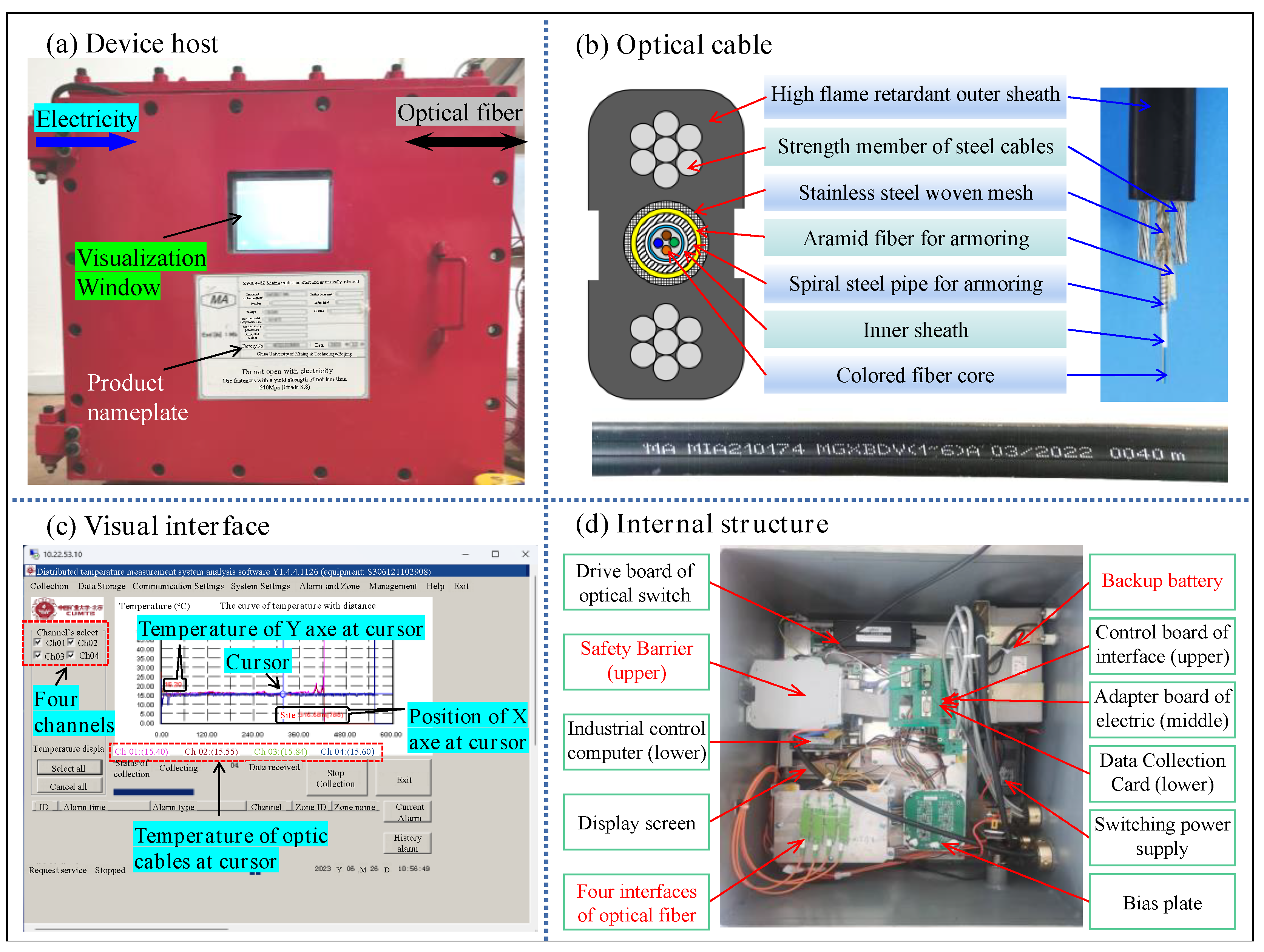
In this work, a new DTSS technology that can be used in coal mine gob is proposed [44,45]. Figure 3 shows the complete DTSS set. Figure 3a illustrates the fiber optic device host. The left side of the device host is the power supply, the right side is the signal transmission interface, and the screen in the middle of DTSS is a visualization window that can directly display the detected temperature data. Figure 3b illustrates the optical cable used for temperature measurement. The design of a flat appearance increases the temperature detection area; the design of parallel steel cable reinforcement enables the optical cable to have very strong compressive and impact resistance. Figure 3c illustrates the software interface displayed in the visualization window, which can display the position and temperature values of a certain point on the optical cable. The horizontal axis of the coordinate map represents the length of the optical cable, and the vertical axis represents the temperature value detected by the optical cable. Figure 3d illustrates the internal structure of the detection host, where the device has added safety barriers and backup batteries to improve safety performance and prevent the impact of power outages. In addition, the bias plate component used can conduct small signals and improve the signal−to−noise ratio.

2.4. Performance Characteristics

This product has obtained a safety label certificate (No. MFE230006) for mining products and is classified as explosion−proof and intrinsically safe equipment.
Table 1 shows the performance parameters of the device host, with a high positioning accuracy of 0.4 m, a temperature measurement accuracy of 1.54 °C, and a reaction time of 2 s, which can be applied to multi−mode optical fiber with a diameter of 62.5/125 μm. It has four channels and can be connected to four optical cables. The working current is 800 mA.

3. Comparative Experiment of Casing on Optical Cable

3.1. Testing Method

The environment of underground gob is relatively harsh, and optical cables may break and be damaged under the high stress of falling rocks. We propose a protection method that uses high−pressure rubber hoses as casing pipes on the optical cables. To determine the effect of the protective pipe on the detection results, a comparison experiment was designed and performed without and with the protective pipe, and the changes in the temperature value and temperature sensing speed were analyzed.
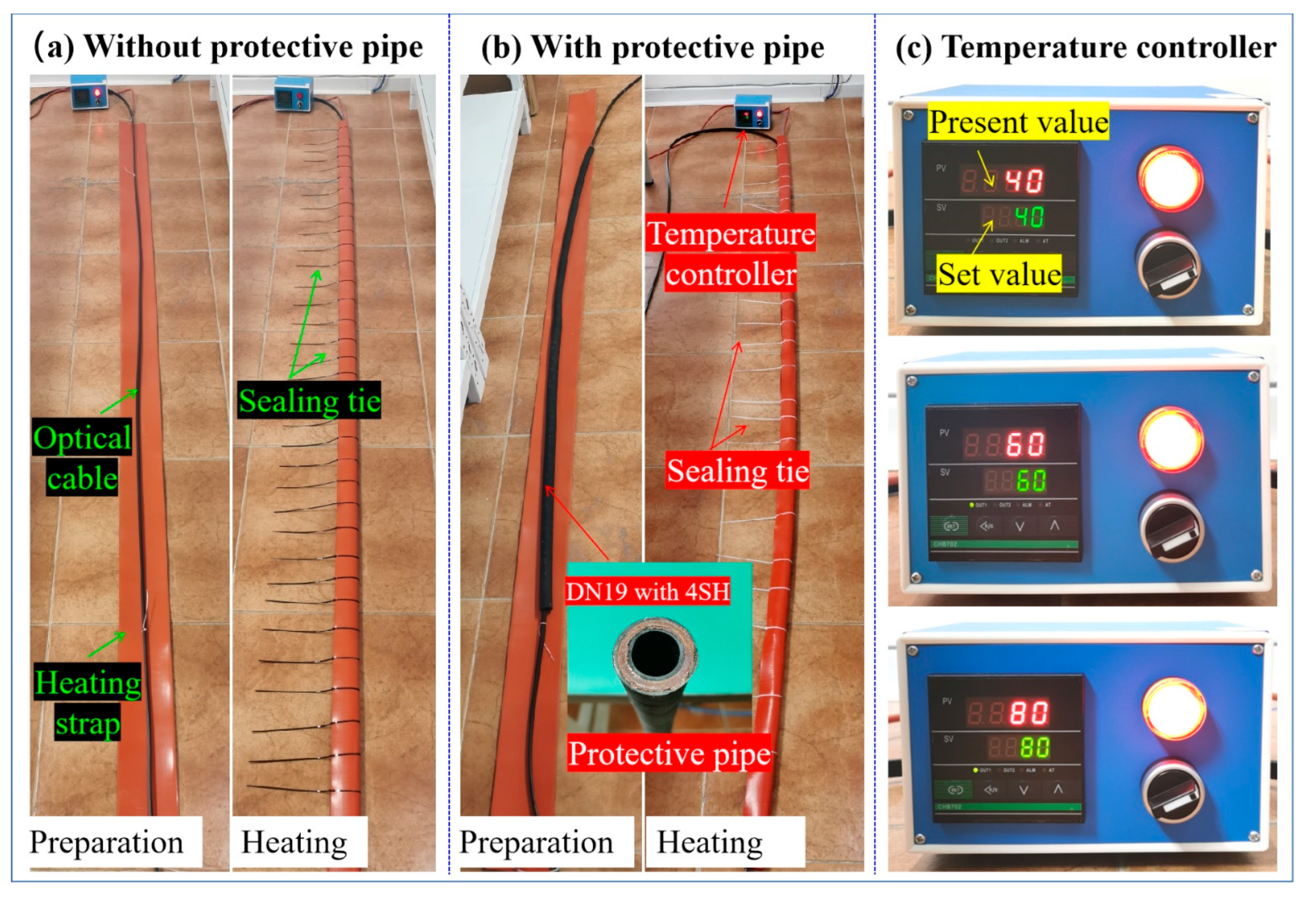
The test design is shown in Figure 4. A silicone flexible electric heating film connected to a PID temperature controller is used as the heating strap for better contact and transfer of heat to the optical cable. The heating strap that wraps around the optical cable is fixed with several sealing strips. A DN19 high−pressure rubber hose with four layers of steel wire winding reinforcement was selected as the protective pipe. The protective pipe can fully meet the requirements for use on gob, with a maximum working pressure of 42.0 MPa and a minimum blasting pressure of 168.0 MPa.
The length of the optical cable for heating is 2 m, the length of the high−pressure rubber hose is 2 m, and the length of the heating strip wrapped externally is 3 m. The detection temperatures are set at 40 °C, 60 °C, and 80 °C, respectively.
During the experiment, PID was used to control the temperature to the present value, and then, the temperature detected by the optical cable within 70 min was observed. A set of data was exported every 1 min by the device host. And the heating strap temperature could increase to 60 °C and 80 °C sequentially after the first temperature detection was finished.

3.2. Analysis of Temperature Value Accuracy

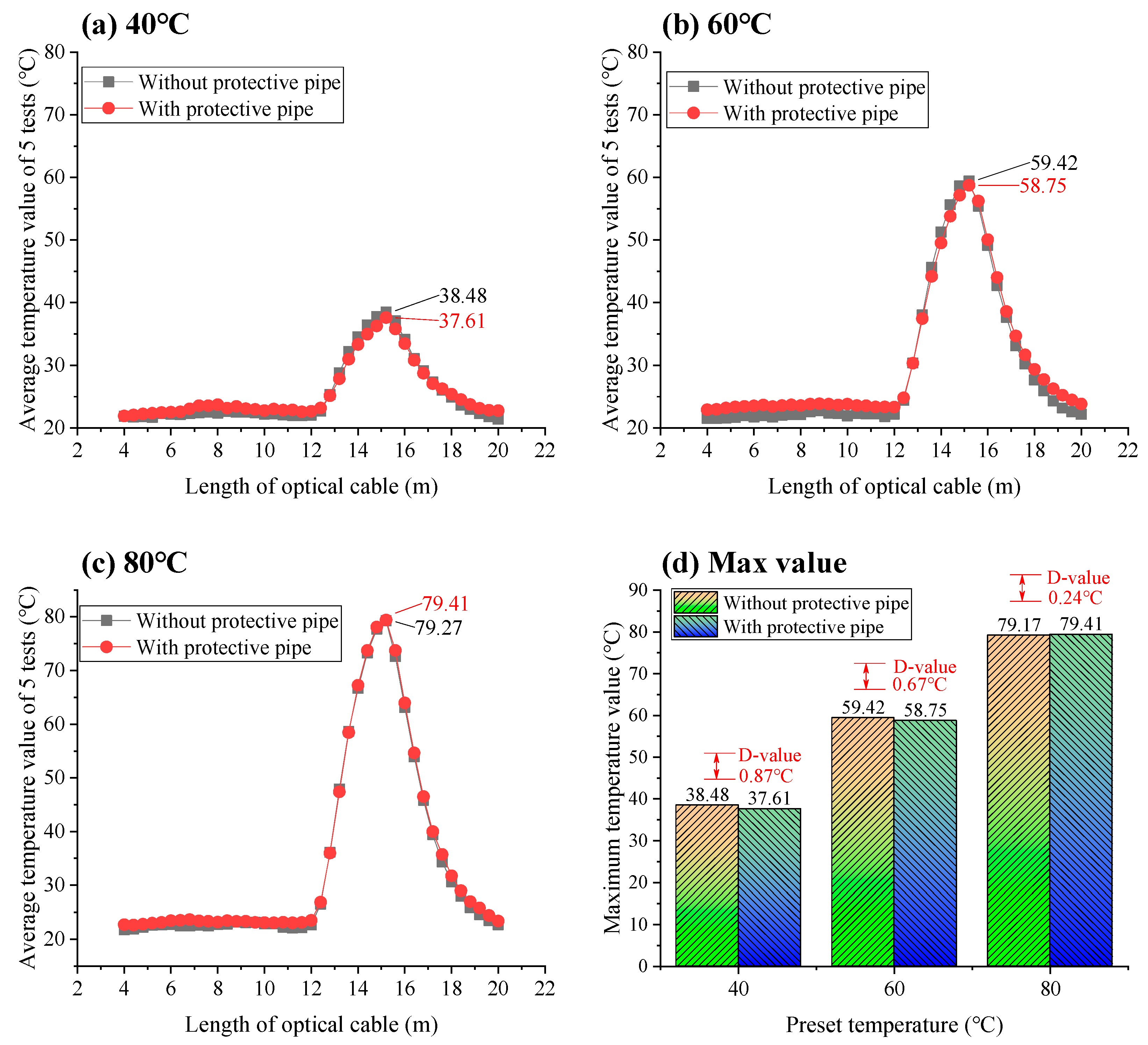
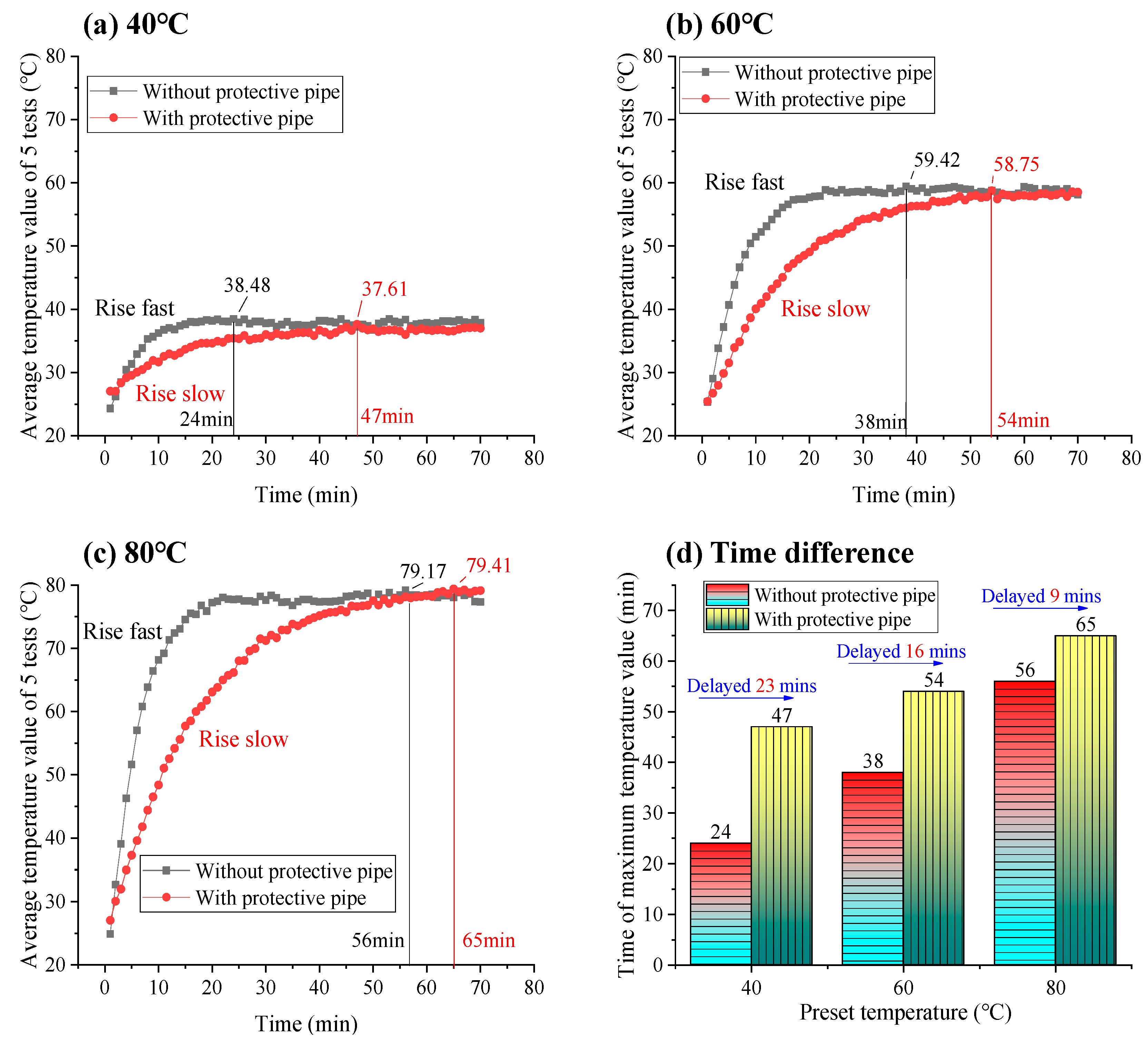
Figure 5 indicates the changes in temperature values detected without and with the protective pipe. The horizontal axis is the length of the optical cable, and the vertical axis is the average temperature value of five tests. From Figure 5, the maximum detection temperature values for the three preset temperatures (40 °C, 60 °C, and 80 °C) without the protective pipe are 38.48 °C, 59.42 °C, and 79.27 °C, respectively. After using the protective pipe, the maximum detection temperature values for the three preset temperatures are 37.21 °C, 58.75 °C, and 79.41 °C, respectively. The differences between the two experiments are 0.87 °C, 0.67 °C, and 0.24 °C, and neither of them exceed 1 °C, as shown in Figure 5d. And the trend of their temperature changes is consistent, which indicates that the influence of the protective pipe on the temperature value is very small and can be ignored.
In addition, it is worth noting that the lengths with temperature variations at the three different set temperatures were all 12–20 m, which is more than the heating length of 3 m. This length with increased temperature distribution is the response distance, which conforms to the temperature measurement principle of the temperature measurement system [46]. The test temperature only affects the value of the response temperature and does not change the response distance (length with increased temperature distribution).

3.3. Analysis of the Speed of Temperature Sensing

In order to understand the influence of the protective pipe on the temperature sensing speed, the temperature detected at the highest temperature measuring point within 70 min was analyzed over time without and with the protective pipe, as shown as Figure 6. The maximum temperature values without the protective pipe appear at 24 min, 38 min, and 56 min, respectively. After using the protective pipe, they are delayed to 47 min, 54 min, and 65 min, respectively, and delayed for 23 min, 16 min, and 9 min, respectively. In addition, the temperature rises rapidly in the first 10 min without the protective pipe. And after using the protective pipe, the overall temperature rise rate is very slow and there is no sharp increase.
Overall, although the time required for the temperature detection value to stabilize after using the protective pipe increases, the final temperature value is basically unchanged, and this lag time can be ignored for large−scale gob. Therefore, using protective pipe to protect optical cables in gob will not affect the accuracy of the temperature values.

4. Application

4.1. Field Temperature Measuring Design

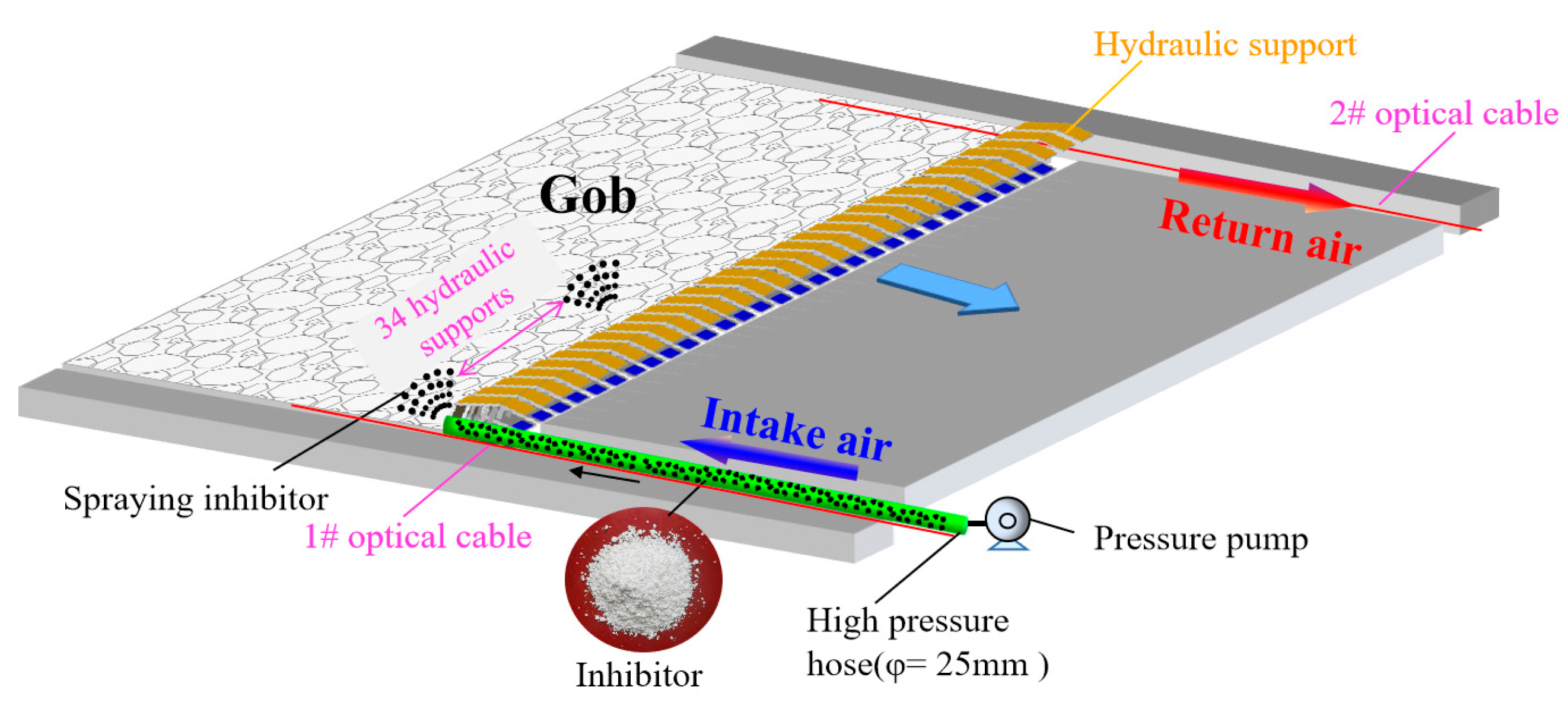
The Wangyun Coal Mine, located in Shanxi Province, China, has an annual output of 1.8 million tons. Currently, the 15th coal seam is being mined, with a thickness of 4.7 m and an oxygen absorption capacity of 0.84 cm3/g, classified as type II spontaneous combustion coal seam. The cut length of the 15106 working face currently being mined is 180 m. In order to grasp the real-time spontaneous combustion status of residual coal in gob, the DTSS proposed in this work was used to monitor the temperature changes in the gob. Figure 7 illustrates the application design of the DTSS, with the 1# and 2# optical cables distributed on both sides of the roadway with the protective pipes. The DN19 high-pressure rubber hose with four layers of steel wire winding reinforcement was selected as the protective pipe, and its safety sign number is MEE150868. The protective pipes are each 10 m long, with a screw joint machined at each end. An optical cable is laid in the roadway, and then, the first protective pipe is placed on the optical cable at the working face and pulled to the entrance of the roadway. Then, this is repeated with the remaining protective pipes inserted. After all the protective pipes have been installed, the joint between the two protective pipes is tightened to complete the installation.
One end of the optical cable with an E2000 fiber optic connector enters the device host. And as the working face advances, the other end, beginning a 0 m, is buried in the gob. The connection box of power supplies power to the device host. The temperature signal demodulated by the device host is transmitted to the ground computer through a network switch and the 3# transmission optical cable, which achieves the ground monitoring of temperature data in the underground gob.

4.2. Application Effect

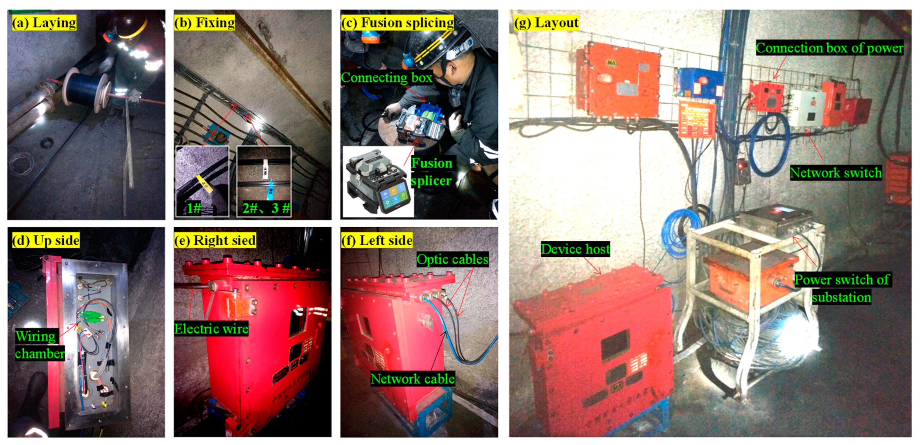
Figure 8 shows the construction of each part of the DTSS on-site, and Figure 8a,b show the laying of optical cables with identification labels on them. Subsequently, the wiring work is completed using a fusion splicer. The connection of optical cables, electric cables, and network cables to the device host is completed in the wiring chamber shown in Figure 8d. The on-site layout of the DTSS is shown in Figure 8g.
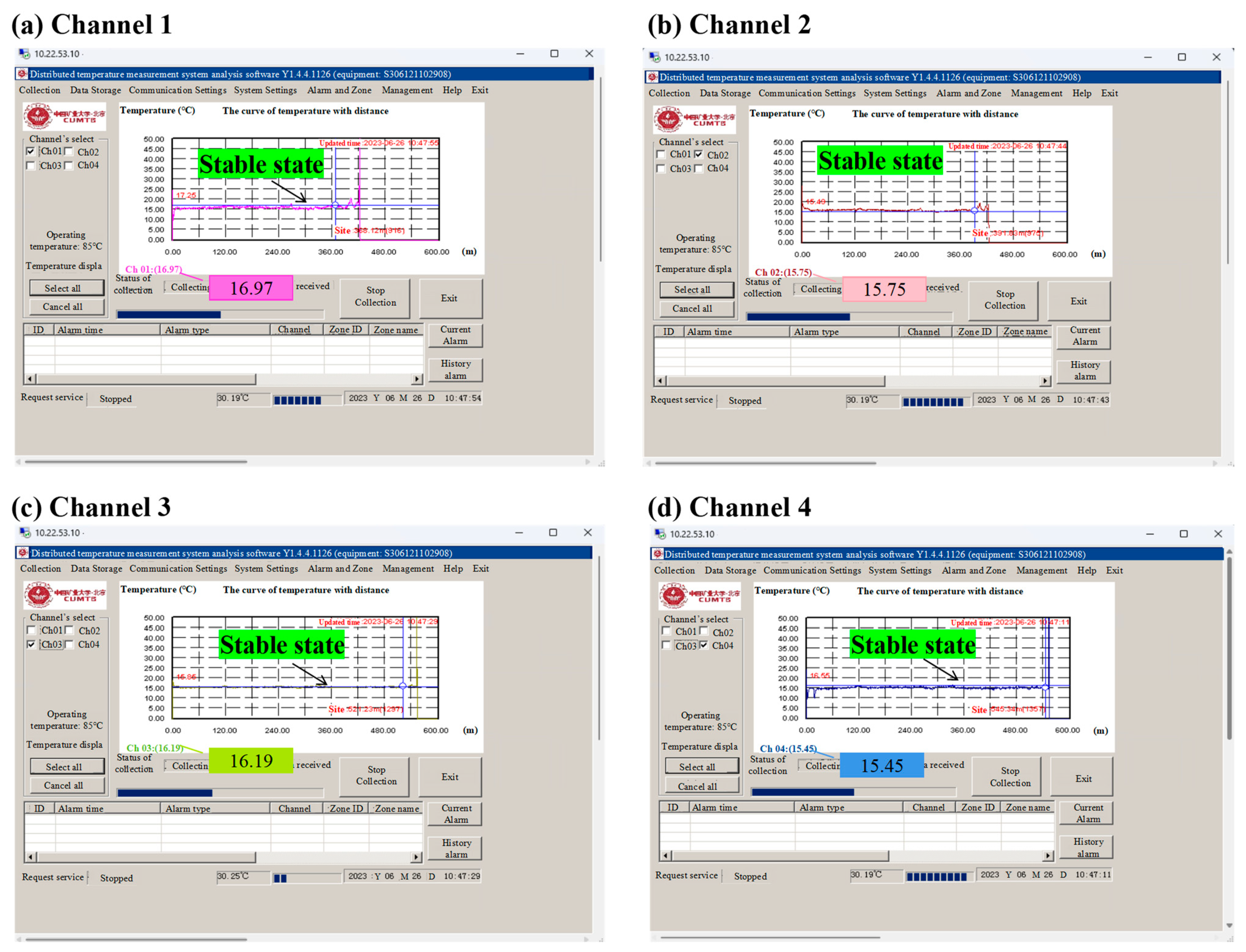
After the completion of the DTSS, the system software of the ground computer obtains temperature data from four channels, as shown in Figure 9. The optical cables used in this work are dual-mode with two cores (double insurance), so channel 1 and channel 2 display the temperature data of the 1# optical cable, while channel 3 and channel 4 display the temperature data of the 2# optical cable. The temperature data detected by the four channels has a certain degree of fluctuation, but the difference is not significant, and the temperature on the entire optical cable remains stable. Real-time data show that the temperature of the gob is between 15.45~16.97 °C, with an average value of 16.09 °C. It should be noted that there is an irregular fluctuation in temperature at the end of each channel, which is a normal disturbance phenomenon at the end of the optical cable and can be ignored.

4.3. Evaluation of the Effectiveness of Inhibitors

The above research indicate that the DTSS established in this work can accurately monitor temperature changes in gob areas. In addition, the DTSS can effectively support the prevention and control of natural fires. During the use of the DTSS, a geological formation appeared while the 15,106 working face advanced to the position of 347 m. This resulted in a decrease in forward speed and a decrease in daily forward length from 2.4 m to 0.5 m. A certain range of gob behind the working face has been in the oxidation zone for a long time. The temperature monitored by the optical cable of the DTSS on 26 June 2023 showed that the temperature in the gob at 18 m behind the working face (with an optical cable length of 399.6 m) was about 20 °C, which was 4 °C higher than normal.
To control the increase in temperature after receiving the warning information issued by the DTSS, the method of using spray inhibitors in the gap between the hydraulic supports was employed to suppress the oxidation reaction of residual coal. Figure 10 shows the spraying process of the inhibitor solution. The inhibitor is industrial calcium chloride (CaCl2·5H2O), with a concentration of 15%. The mixed inhibitor solution was delivered to the working surface through a pressure pump of model BZ-40/2.5 (manufactured by Shandong Changye Machinery Equipment Co., Ltd., China), and then, sprayed though a spraying gun from the gap between two hydraulic supports towards the gob, for at least 6 min each time, with a flow rate of no less than 35 L/min. Due to the temperature anomaly point detected by the 1# optical cable being close to the air intake side, inhibitor spraying was designed to be carried out at 60 m (34th hydraulic support) on the air intake side.
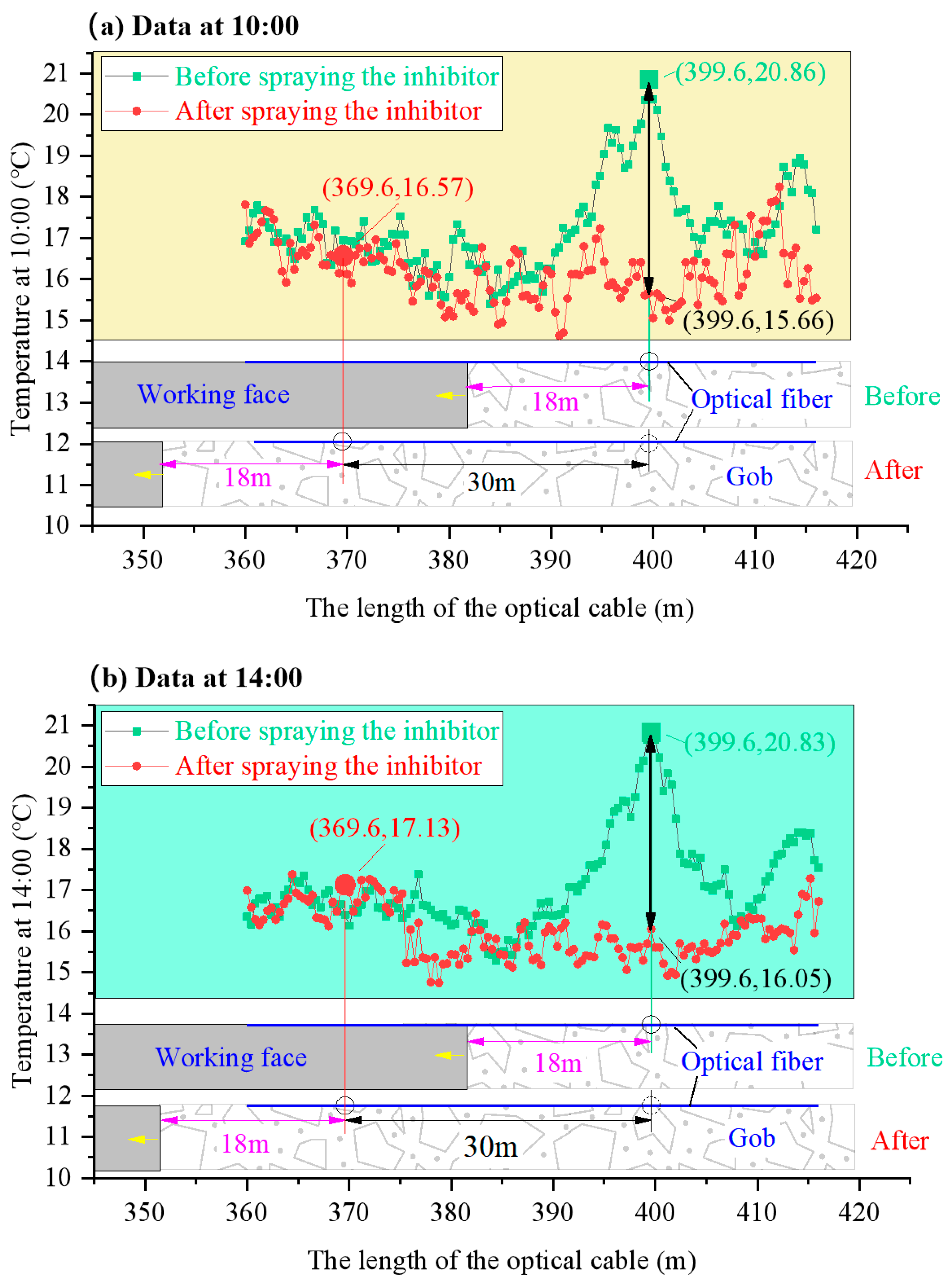
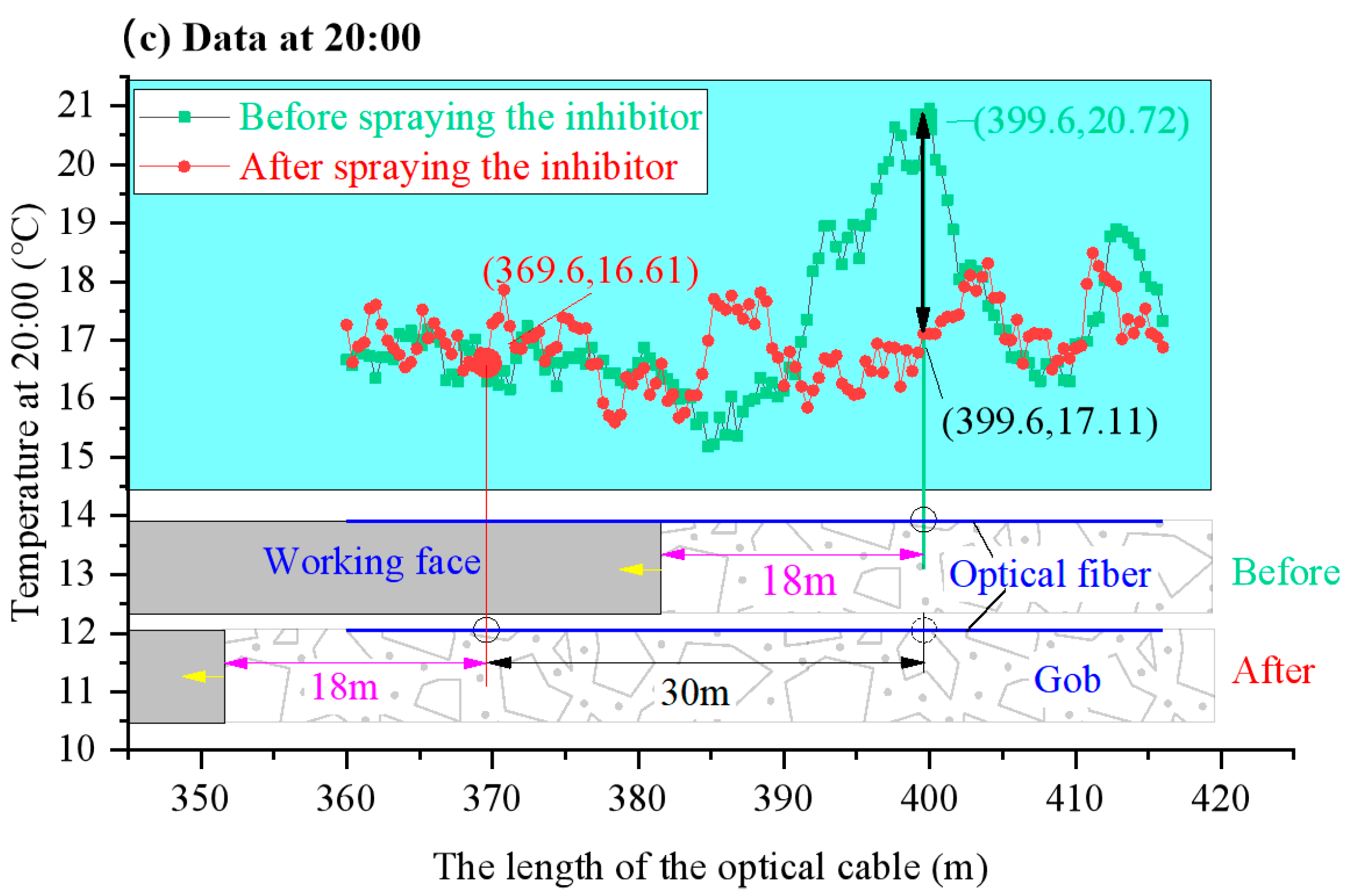
The working face advanced by 30 m within 65 days from 26 June 2023 to 31 August 2023. The effectiveness of the inhibitor solution was evaluated through temperature changes monitored by the 1# optical cable of the DTSS. Figure 11 shows the temperature values of the gob on the air intake side. In order to improve the reliability of data comparison, temperature data from 10:00 am, 14:00 pm, and 20:00 pm one day before and after spraying were selected. The data before spraying were selected from 26 June 2023, and the data after spraying were selected from 31 August 2023.
What can be seen from Figure 11 is the following: ① Before spraying the inhibitor solution, the temperature of the gob at the position 18 m behind the working face (optical cable length 399.6 m) increased to 20.86 °C, 20.83 °C, and 20.72 °C, respectively. After using the inhibitor solution, the temperature of the gob with a relative delay of 18 m (cable length 369.6 m) was 16.57 °C, 17.13 °C, and 16.61 °C, respectively, decreasing by 4.29 °C, 3.7 °C, and 4.11 °C, respectively. The average temperature decreased from 20.8 °C to 16.77 °C, with a decrease of 19.38%. This means that the temperature of the gob behind the working face returned to a normal temperature. ② After 65 days of advancing the working face, the point at 399.6 m of the optical cable changed from 18 m to 48 m behind the working face, and the temperature at this position also decreased to 16.05 °C, 15.66 °C, and 17.11 °C, respectively. The average temperature at this point decreased from 20.8 °C to 16.27 °C, with a decrease of 21.78%. This indicates that the risk of coal spontaneous combustion in this area was eliminated. ③ These temperature changes indicate that the adopted inhibitor spray measures effectively suppressed the oxidation and exothermic effect of residual coal, and the DTSS used strongly supports the safety of production work in the coal mine.
This product and technology have greatly improved the monitoring and warning capabilities of CSC hazards in gob.

5. Conclusions

In this work, a monitoring and early warning system suitable for harsh environments in gob, called the distributed optical fiber temperature sensing system, was developed and successfully applied to monitoring and evaluating the degree of CSC in a coal mine in China. The main conclusions are summarized below:
  • The internal parallel steel cables and the external protective pipe improved the anti-damage ability of the optical cables. The technology of the protective pipe only increases the time required for detecting the actual temperature and does not affect the accuracy of temperature measurement. The temperature difference before and after use of the protective pipe is only 0.87 °C, 0.67 °C, and 0.24 °C, respectively. So, the protective pipe can be used with confidence.
  • The technology of the DTSS could improve early warning ability for preventing the risk of CSC in gob. This technology can detect abnormal temperature conditions in gob in a timely manner. Through the monitoring and evaluation of the DTSS, the average temperature at the same location in the gob after spraying the inhibitor returned from 20.8 °C to 16.27 °C, with a decrease of 21.78%, which means the risk of CSC in the gob was eliminated.
  • This study only analyzes the application effect of DTSS technology in coal mine gob, which is not comprehensive enough. So, in the future, to enrich these research findings, comparative research on other measurement methods, such as temperature measurement methods of thermal resistance, will be carried out. In addition, we also hope to use the DTSS for in-depth research in different scenarios.

Author Contributions

Conceptualization, F.Z. and Y.Q.; methodology, F.Z.; formal analysis, F.Z., D.H. and H.X.; investigation, F.Z., D.Z. and S.P.; resources, Z.X.; data curation, D.H.; writing—original draft preparation, F.Z.; writing—review and editing, F.Z. and F.T.; project administration, Y.Q.; visualization, F.Z.; funding acquisition, F.Z. and Y.Q. All authors have read and agreed to the published version of the manuscript.

Funding

This research was funded by the research fund of the National Natural Science Foundation of China (52074303, 51874315); the Fundamental Research Funds for the Central Universities (2022JCCXAQ06); and the project of the Basic Research Business Fee of China University of Mining and Technology (Beijing)—Top Innovative Talents Cultivation Fund for Doctoral Students (BBJ2023011). Additionally, we are grateful to the editor and anonymous reviewers for their valuable comments, which improved this paper significantly.

Institutional Review Board Statement

Not applicable.

Informed Consent Statement

Not applicable.

Data Availability Statement

Not applicable.

Acknowledgments

We are grateful to the editor and anonymous reviewers for their valuable comments, which improved this paper significantly.

Conflicts of Interest

The authors declare no conflict of interest.

References

  1. Danish, E.; Onder, M. Application of Fuzzy Logic for Predicting of Mine Fire in Underground Coal Mine. Saf. Health Work. 2020, 11, 322–334. [Google Scholar] [CrossRef] [PubMed]
  2. Hao, M.; Li, Y.; Song, X.; Kang, J.; Su, H.; Zhou, F. Hazardous areas determination of coal spontaneous combustion in shallow-buried gobs of coal seam group: A physical simulation experimental study. Environ. Earth Sci. 2019, 78, 39. [Google Scholar] [CrossRef]
  3. Liu, W.; Qin, Y. Multi-physics coupling model of coal spontaneous combustion in longwall gob area based on moving coordinates. Fuel 2017, 188, 553–566. [Google Scholar] [CrossRef]
  4. Jiang, X.; Yang, S.; Zhou, B.; Lan, L. The auto-oxidation characteristic of coal at different stages of the low-temperature oxidation process. Fuel 2023, 352, 129130. [Google Scholar] [CrossRef]
  5. Liu, W.; Zhang, F.; Gao, T.; Chu, X.; Qin, Y. Efficient prevention of coal spontaneous combustion using cooling nitrogen injection in a longwall gob: An application case. Energy 2023, 281, 128214. [Google Scholar] [CrossRef]
  6. Qiao, M.; Ren, T.; Roberts, J.; Yang, X.; Li, Z.; Wu, J. Insight into proactive inertisation strategies for spontaneous combustion management during longwall mining of coal seams with various orientations. Energy Sources Part A Recover. Util. Env. Eff. 2023, 45, 2788–2810. [Google Scholar] [CrossRef]
  7. Saffari, A.; Sereshki, F.; Ataei, M.; Ghanbari, K. Presenting an engineering classification system for coal spontaneous combustion potential. Int. J. Coal Sci. Technol. 2017, 4, 110–128. [Google Scholar] [CrossRef]
  8. Onifade, M.; Genc, B.; Gbadamosi, A.R.; Morgan, A.; Ngoepe, T. Influence of antioxidants on spontaneous combustion and coal properties. Process Saf. Environ. Prot. 2021, 148, 1019–1032. [Google Scholar] [CrossRef]
  9. Si, R.; Li, R. Dynamic characteristics of low-concentration oxygen-containing gas explosion and prevention and control key technologies. Coal Sci. Technol. 2020, 48, 17–36. [Google Scholar] [CrossRef]
  10. Ma, D.; Qin, B.; Gao, Y.; Jiang, J.; Feng, B. An experimental study on the methane migration induced by spontaneous combustion of coal in longwall gobs. Process Saf. Environ. Prot. 2021, 147, 292–299. [Google Scholar] [CrossRef]
  11. Ranjith, P.G.; Zhao, J.; Ju, M.; De Silva, R.V.S.; Rathnaweera, T.D.; Bandara, A.K.M.S. Opportunities and Challenges in Deep Mining: A Brief Review. Engineering 2017, 3, 546–551. [Google Scholar] [CrossRef]
  12. Zhang, L.; Wu, W.; Bian, Y.; Yang, M.; Luo, H. Influences of Gas Drainage Pipe Positions on Spontaneous Coal Combustion in the Gob: A Case Study of Baode Coal Mine in China. Combust. Sci. Technol. 2022, 194, 3357–3373. [Google Scholar] [CrossRef]
  13. Zou, J.; Zhang, R.; Zhou, F.; Zhang, X. Hazardous Area Reconstruction and Law Analysis of Coal Spontaneous Combustion and Gas Coupling Disasters in Goaf Based on DEM-CFD. ACS Omega 2023, 8, 2685–2697. [Google Scholar] [CrossRef]
  14. Shadab, A.; Ansari, M.T.I.; Raghuwanshi, S.K.; Kumar, S. Smoke Detection Using rGO-Coated eFBG Sensor for Early Warning of Coal Fire in Mines. IEEE Sens. J. 2023, 23, 2153–2160. [Google Scholar] [CrossRef]
  15. Liu, C.; Zhang, R.; Wang, Z.; Zhang, X. Research on the fire extinguishing performance of new gel foam for preventing and controlling the spontaneous combustion of coal gangue. Environ. Sci. Pollut. Res. 2023, 30, 88548–88562. [Google Scholar] [CrossRef]
  16. Deng, J.; Zhou, J.; Bai, Z.; Liu, L.; Wang, C. Effect of gas on microstructure and thermal reactivity of coal during low temperature oxidation. Coal Sci. Technol. 2023, 51, 304–312. [Google Scholar] [CrossRef]
  17. Zhao, X.; Sun, P.; Yang, J.; Zhang, Z.; Zhang, L.; Tang, Y.; Sun, M.; Pang, T.; Liu, X.; Xu, Q. Online monitoring system of index gases concentration applied to coal sponta-neous combustion. Meitan Xuebao/J. China Coal Soc. 2021, 46, 319–327. [Google Scholar] [CrossRef]
  18. Song, W.X.; Yang, S.Q.; Jiang, C.L.; Niu, J. Experimental research on the formation of CO during coal spontaneous combustion under the condition of methane-contained airflow. J. China Coal Soc. 2012, 37, 1320–1325. [Google Scholar] [CrossRef]
  19. Cheng, J.; Ma, Y.; Lu, W.; Liu, G.; Cai, F. Using inverting CO critical value to predict coal spontaneous combustion severity in mine gobs with considering air leakages—A case study. Process Saf. Environ. Prot. 2022, 167, 45–55. [Google Scholar] [CrossRef]
  20. Wang, K.; Li, Y.; Zhang, Y.; Deng, J. An approach for evaluation of grading forecasting index of coal spontaneous combustion by temperature-programmed analysis. Environ. Sci. Pollut. Res. 2023, 30, 3970–3979. [Google Scholar] [CrossRef]
  21. Tan, B.; Shao, Z.; Guo, Y.; Zhao, T.; Zhu, H.; Li, C. Research on grading and early warning of coal spontaneous combustion based on correlation analysis of index gas. China Saf. Sci. J. 2021, 31, 33–39. [Google Scholar] [CrossRef]
  22. Deng, J.; Xiao, Y.; Li, Q.; Lu, J.; Wen, H. Experimental studies of spontaneous combustion and anaerobic cooling of coal. Fuel 2015, 157, 261–269. [Google Scholar] [CrossRef]
  23. Zhang, J. Current Situation and Development Trend of Coal Mine Beam Tube Monitoring System. Saf. Coal Mines 2019, 50, 89–92. [Google Scholar] [CrossRef]
  24. Kong, D.; Pu, S.; Cheng, Z.; Wu, G.; Liu, Y. Coordinated Deformation Mechanism of the Top Coal and Filling Body of Gob-Side Entry Retaining in a Fully Mechanized Caving Face. Int. J. Geomech. 2021, 21, 04021030. [Google Scholar] [CrossRef]
  25. Qin, Y.; Yan, L.; Liu, W.; Xu, H.; Song, Y.; Guo, W. Continuous monitoring system of gob temperature and its application. Environ. Sci. Pollut. Res. 2022, 29, 53063–53075. [Google Scholar] [CrossRef]
  26. Wu, S.; Zhou, B.; Wang, J.; Yang, Q.; Dong, W.; Dong, Z. Isotope radon measurement method to identify spontaneous combustion regions in coal gangue hills: Case study for a coal mine in China. Int. J. Coal Prep. Util. 2023, 1–13. [Google Scholar] [CrossRef]
  27. Gao, Y.; Hao, M.; Wang, Y.; Dang, L.; Guo, Y. Multi-scale coal fire detection based on an improved active contour model from landsat-8 satellite and UAV images. ISPRS Int. J. Geo-Inf. 2021, 10, 449. [Google Scholar] [CrossRef]
  28. Li, F.; Li, J.; Liu, X.; Meng, X. Coal fire detection and evolution of trend analysis based on CBERS-04 thermal infrared imagery. Environ. Earth Sci. 2020, 79, 1–15. [Google Scholar] [CrossRef]
  29. Sun, Y.; Luo, X.; Gao, Y.; Ren, Q.; Wang, P.; He, Y. Application of the radioactive waveperspective technology to goaf detection in the coal mine resource integration. J. Saf. Environ. 2020, 20, 533–547. [Google Scholar] [CrossRef]
  30. Sun, M.; Tang, Y.; Yang, S.; Li, J.; Sigrist, M.W.; Dong, F. Fire source localization based on distributed temperature sensing by a dual-line optical fiber system. Sensors 2016, 16, 829. [Google Scholar] [CrossRef]
  31. Su, H.; Ou, B.; Yang, L.; Wen, Z. Distributed optical fiber-based monitoring approach of spatial seepage behavior in dike engineering. Opt. Laser Technol. 2018, 103, 346–353. [Google Scholar] [CrossRef]
  32. Zhong, X.; Wang, J.; Zhou, K. Monitoring and early warning technology of coal spontaneous combustion in coal mines: Research status and intelligent development trends. Ind. Mine Autom. 2021, 47, 7–17. [Google Scholar] [CrossRef]
  33. Shan, Y.; Ma, Y.; Fu, H.; Li, W.; Wang, C. Application of distributed optical fiber temperature measurement system in coal mine fire monitoring system. Chin. J. Sens. Actuators 2014, 27, 704–708. [Google Scholar] [CrossRef]
  34. Hou, G.; Hu, Z.; Li, Z.; Zhao, Q.; Feng, D.; Cheng, C.; Zhou, H. Present situation and prospect of coal mine safety monitoring based on fiber bragg grating and distributed optical fiber sensing technology. J. China Coal Soc. 2023, 48, 96–110. [Google Scholar] [CrossRef]
  35. Tereshchenko, E.R.; Shishlakov, V.F.; Gubanova, N.A.; Leonteva, A.B.; Manzuk, M.V. Application of Fiber Optic Temperature Sensor in the Development of a Distributed Data Acquisition System. In Proceedings of the 2021 IEEE Conference of Russian Young Researchers in Electrical and Electronic Engineering (ElConRus), St. Petersburg, Russia, 26–29 January 2021; Volume 2021, pp. 1111–1112. [Google Scholar] [CrossRef]
  36. Du, C.; Hu, T.; Li, Y.; Wang, J. Feasibility study on distributed optical fiber monitoring of coal roadway roof. Min. Saf. Environ. Prot. 2022, 49, 81–88. [Google Scholar] [CrossRef]
  37. Viveiros, D.; Ribeiro, J.; Ferreira, J.; Pinto, A.M.R.; Perez-Herrera, R.A.; Diaz, S.; Lopez-Gil, A.; Dominguez-Lopez, A.; Esteban, O.; Martins, H.F.; et al. Monitoring of coal waste piles with fiber optic sensing technology. In Proceedings of the 2015 3rd Experiment International Conference (exp. at’15), Ponta Delgada, Portugal, 2–4 June 2015; pp. 147–148. [Google Scholar] [CrossRef]
  38. Ashry, I.; Mao, Y.; Wang, B.; Hveding, F.; Bukhamsin, A.Y.; Ng, T.K.; Ooi, B.S. A Review of Distributed Fiber-Optic Sensing in the Oil and Gas Industry. J. Light. Technol. 2022, 40, 1407–1431. [Google Scholar] [CrossRef]
  39. Kus, J. Impact of underground coal fire on coal petrographic properties of high volatile bituminous coals: A case study from coal fire zone No. 3.2 in the Wuda Coalfield, Inner Mongolia Autonomous Region, North China. Int. J. Coal Geol. 2017, 171, 185–211. [Google Scholar] [CrossRef]
  40. Kus, J. Oxidatively and thermally altered high-volatile bituminous coals in high-temperature coal fire zone No. 8 of the Wuda Coalfield (North China). Int. J. Coal Geol. 2017, 176–177, 8–35. [Google Scholar] [CrossRef]
  41. Zhu, L.; Gu, W.; Chai, J.; Ma, Z.; Qiu, F. Evolution of mining-induced overburden deformation using distributed optical fiber. J. Min. Strat. Control Eng. 2022, 4, 013014. [Google Scholar] [CrossRef]
  42. Zhang, Z.; Wang, J.; Yu, X.; Guo, N.; Wu, X.; Feng, H.; Insoo, S.; Sangki, O.; Yohee, K. The Research of Raman Type Distributed Optical Fiber Temperature Measuring Method. J. Optoelectron. 2001, 12, 596–600. [Google Scholar]
  43. Wen, H.; Wu, K.; Ma, L.; Wang, W.; Wang, T. Application of Distributed Optical Fiber Temperature Measurement System in Monitoring Goaf Coal Spontaneous Combustion. Saf. Coal Mines 2014, 5, 100–105. [Google Scholar] [CrossRef]
  44. Li, Z.; Li, F.; Wang, K.; Gao, X. Application of Distributed Optical Fiber Temperature Measurement System in Wanglou Coal Mine. Coal Technol. 2020, 39, 156–158. [Google Scholar] [CrossRef]
  45. Su, H.; Zhou, F.; Song, X.; Qiang, Z. Risk analysis of spontaneous coal combustion in steeply inclined longwall gobs using a scaled-down experimental set-up. Process Saf. Environ. Prot. 2017, 111, 1–12. [Google Scholar] [CrossRef]
  46. Ning, F.; Zhu, Y.; Cui, H.; Li, X.; Jin, Z. A Linear Correction Algorithm for Improving the Spatial Resolution of Distributed Fiber Optic Temperature Measurement System. Acta Photonica Sin. 2012, 41, 408–413. [Google Scholar] [CrossRef]
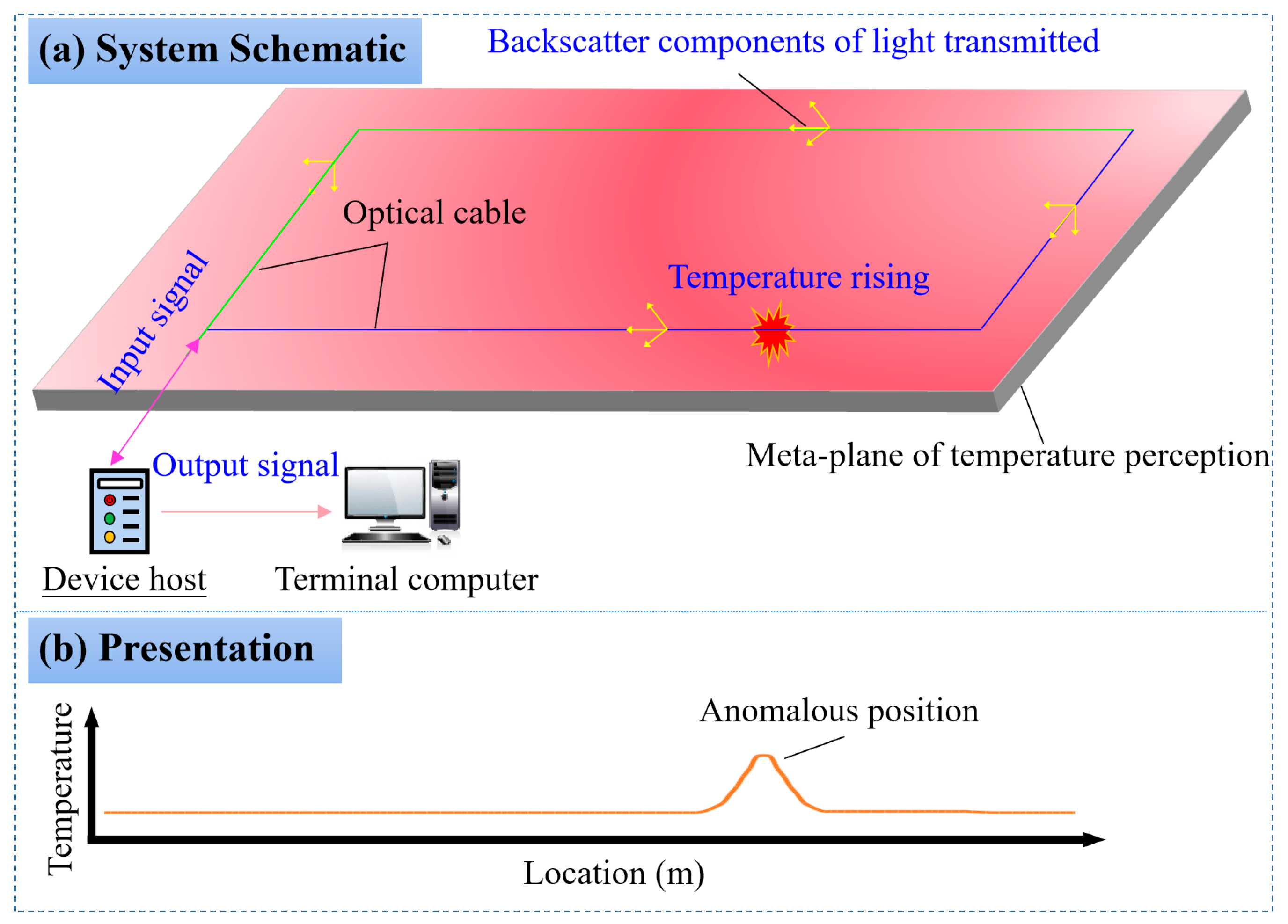
Figure 1. Technical principle of DTSS. (a) System schematic (b). Presentation.
Fire 06 00410 g001
Figure 2. Demodulation process.
Fire 06 00410 g002
Figure 3. Complete DTSS. set (a) Device host. (b) Optical cable. (c) Visual interface. (d) Internal structure.
Fire 06 00410 g003
Figure 4. Test without and with protective pipe. (a) Without protective pipe. (b) With protective pipe, (c) Temperature controller.
Fire 06 00410 g004
Figure 5. Comparison of temperature values without and with protective pipe. (a) 40 °C. (b) 60 °C. (c) 80 °C. (d) Max value.
Fire 06 00410 g005
Figure 6. Comparison of temperature sensing speed without and with protective pipe. (a) 40 °C. (b) 60 °C. (c) 80 °C. (d) Time difference.
Fire 06 00410 g006
Figure 7. Application design of DTSS in gob.
Fire 06 00410 g007
Figure 8. Construction effect of DTSS. (a) Laying. (b) Fixing. (c) Fusion splicing. (d) Top side. (e) Right side. (f) Left side. (g) Layout.
Fire 06 00410 g008
Figure 9. Results of temperature detection. (a) Channel 1. (b) Channel 2. (c) Channel 3. (d) Channel 4.
Fire 06 00410 g009
Figure 10. Spraying process of inhibitor.
Fire 06 00410 g010
Figure 11. Comparison of temperature before and after praying the inhibitors after 65 days. (a) Data at 10:00. (b) Data at 14:00. (c) Data at 20:00.
Fire 06 00410 g011aFire 06 00410 g011b
Table 1. Performance parameters.
Performance IndexParameters
Supply voltageAC127V
Working current800 mA
Number of channelsFour
Distance for temperature measurement4 km for one channel
Scope of temperature(0~100) °C
Spatial resolution2 m
Accuracy of positioning≤±0.4 m
Accuracy of temperature1.54 °C
Response time2 s
Wavelength of the detection light1550 nm
Emission power of the detection light≤0 dbm
Communication interfaceRJ45, RS485
Type of fiber that can be connectedMulti−mode optical fiber: 62.5/125 μm
Inside connectors of optical fiberE2000
Disclaimer/Publisher’s Note: The statements, opinions and data contained in all publications are solely those of the individual author(s) and contributor(s) and not of MDPI and/or the editor(s). MDPI and/or the editor(s) disclaim responsibility for any injury to people or property resulting from any ideas, methods, instructions or products referred to in the content.