Article

A Parametric Study of Fire Risks of Green Roofs to Adjacent Buildings

1
NSERC Industrial Research Chair on Eco-Responsible Wood Construction (CIRCERB), Department of Wood and Forest Sciences, Université Laval, Québec City, QC G1V 0A6, Canada
2
FPInnovations, Québec City, QC G1V 4C7, Canada
3
Department of Applied Sciences, Université du Québec à Chicoutimi (UCAQ), Chicoutimi, QC G7H 2B1, Canada
4
Department of Civil and Water Engineering, Université Laval, Québec City, QC G1V 0A6, Canada
*
Author to whom correspondence should be addressed.
Submission received: 8 June 2022 / Revised: 25 June 2022 / Accepted: 2 July 2022 / Published: 7 July 2022

Abstract

:
The susceptibility of plants to burn raises concerns about fire hazard that green roofs may pose to buildings. Main concerns relate to cases when such roofs are poorly maintained or stressed by drought conditions which leads to drying out of plants and the accumulation of dead organic material, greatly increasing the availability of fuel load. Existing standard safety measures aim to prevent the spread of fire through the vegetation cover. However, fire spread by thermal radiation is not considered. In this study, fire risk of exposure of adjacent buildings to radiant heat flux produced by fire on green roofs was assessed. Based on generally accepted maximum tolerable radiant heat flux to exposed facades of 12.5 kW/m2, the minimum safe separation distances were obtained for different conditions. Wildland fire behavior model was used to determine flame lengths which is the necessary parameter for a radiation model. Several vegetation types, moisture content scenarios and wind speeds were taken as variables. It was found that by providing the vegetation with reasonably high moisture content the fire risk can be greatly reduced, especially for grass-covered roofs. Since wind also has a strong effect on flame size, considering the exposure of a green roof to wind can bring better understanding of fire risk to adjacent buildings. At no-wind condition and at extremely low moisture content separation distances are as short as 3.1 m for dense shrubs and 2.4 m for tall dense grass.

1. Introduction

Adding vegetated zones in building design, such as green roofs and living wall systems, is becoming increasingly popular [1]. Together with bringing aesthetic value these features serve multiple functions to improve urban ecology and social well-being [2]. Numerous design projects showed the possibility to install a great variety of vegetation from simple grass to gardens with small trees and shrubs. Such zones, however, may be vulnerable parts of the building in terms of fire safety. Roofs usually are large open surfaces with no obstacles where a continuous vegetation cover presents a fuel load that can support fire. In case maintenance work on green roofs is neglected, such as removing of debris and dead plant parts or failure or absence of an irrigation system where it is necessary, the formation of additional fuel load and reduced moisture make the roof subject to fire risk. In the presence of wind and favorable drought conditions the fire can spread and occupy a large area as well as spread to the building and adjacent structures. In the absence of previous researches and evidences of large fires on green roofs it is not clear whether such roofs present a real fire hazard to adjacent buildings.
Fire can spread horizontally by three modes, such as by (1) flying burning brands transported by wind from vegetation in fire, (2) direct contact with flames and (3) thermal radiation [3]. It is the radiation that is mostly responsible for fire spread between buildings, because in such a mode heat can travel long distances without requiring any solid or liquid material between emitting and receiving surfaces [4]. Flames produce a radiant heat flux that when reaching an exposed object can cause its ignition. This heat flux received by the surface of the adjacent wall and the ability of a wall material to withstand a certain level of heat flux, a critical value of exposure, determines the necessary separation distance between possible fire and the receiving surface.
Green roof design in most of the countries contains provisions to limit the spread of fire and to protect the adjacent walls from fire attack by burning brands and direct flame contact. Requirements of non-combustible wall material [5], irrigation and regular maintenance, fire walls, fire breaks between large vegetated areas, separation zones around roof penetrations, equipment [5,6,7,8] and adjoining walls [5,7] greatly reduce the fire risk. To some extent, this is confirmed by the fact that no spread of fire was observed where these rules are properly followed, such as in the Province of Quebec, Canada. Protection of adjacent structures from radiant heat exposure in case of other type of wall material is, however, not considered. Examining the risk of building damages from possible fire on adjacent green roofs can help to ensure the safety of such roofs.
The objective of this study is to assess fire risk of green roofs to adjacent structures by examining the fire attack by thermal radiation. Specifically, based on the critical incident heat flux to an exposed facade of adjacent building, minimum separation distance from a green roof must be determined. Additionally, the effects of parameters, such as wind speed and moisture content, on the minimum separation distance will be explored. The diversity of vegetation will also be considered. For that, several scenarios with varying environmental conditions and vegetation types will be analyzed.

2. Methodology

2.1. Radiation Model

Methods of assessment of horizontal external fire spread between buildings by radiation consider a fire originating inside the building, and heat is emitted by building facade through the openings (e.g., windows). Determination of safe separation distances is based on the knowledge of fire intensity, dimensions of emitting surface and critical radiation heat flux for a receiving surface of opposite building. The commonly accepted value of critical incident heat flux to building facades in Canada is 12.5 kW/m2 [9], which is the amount of heat needed for the piloted ignition of wooden materials with the presence of the ignition source, such as burning brands [10]. The National Building Code of Canada contains tables on separation distances between buildings in relation to maximum allowed area of openings [11]. The tables were elaborated based on an assumption of maximum expected intensity of fire of 180 kW/m2 or 360 kW/m2 for normal and hazardous cases, respectively [9]. Even though 12.5 kW/m2 is conservative for the piloted ignition [3], for this study it was taken as a critical incident heat flux since it is a standard value. Based on the critical heat flux, minimum separation distances to the adjacent facade (d12.5) were obtained.
There are several methods for the determination of heat flux of flames from natural fires such as point source model, solid flame model and rectangular planar (solid planar surface) model. The point source model is considered to be very simplistic because it performs well where incident heat flux is below 5 kW/m2, such as at large distances between the fire and the receiving surface [12,13]. The solid flame model was developed for pool fires, where the base of the flame has a rounded shape. Such geometry can be applicable for spot fires, such as a burning tree [14,15]. For green roofs a rectangular planar model is a better option. It is typically used for natural wildland fires [16,17,18,19], where flames are presented as a box-shaped body of given dimensions that is projected onto a rectangular vertical (radiant) panel, i.e., the emitting surface. Dimensions of this emitting surface and the distance to the receiving object determine the fraction of radiation that reaches the object, and is called shape factor, also known as configuration or view factor.
For all models incident radiant heat flux can be obtained from the following expression [20]:
q ˙ r a d = E τ F
where radiant heat flux is in kW/m2, E is the emissive power (W/m2), τ is the atmospheric transmissivity (dimensionless) and F is the shape factor (dimensionless). Emissive power is the radiative heat flux produced by flames. It depends on the emissivity of the emitting body and flame temperature, and is expressed as:
E = ε σ T f 4
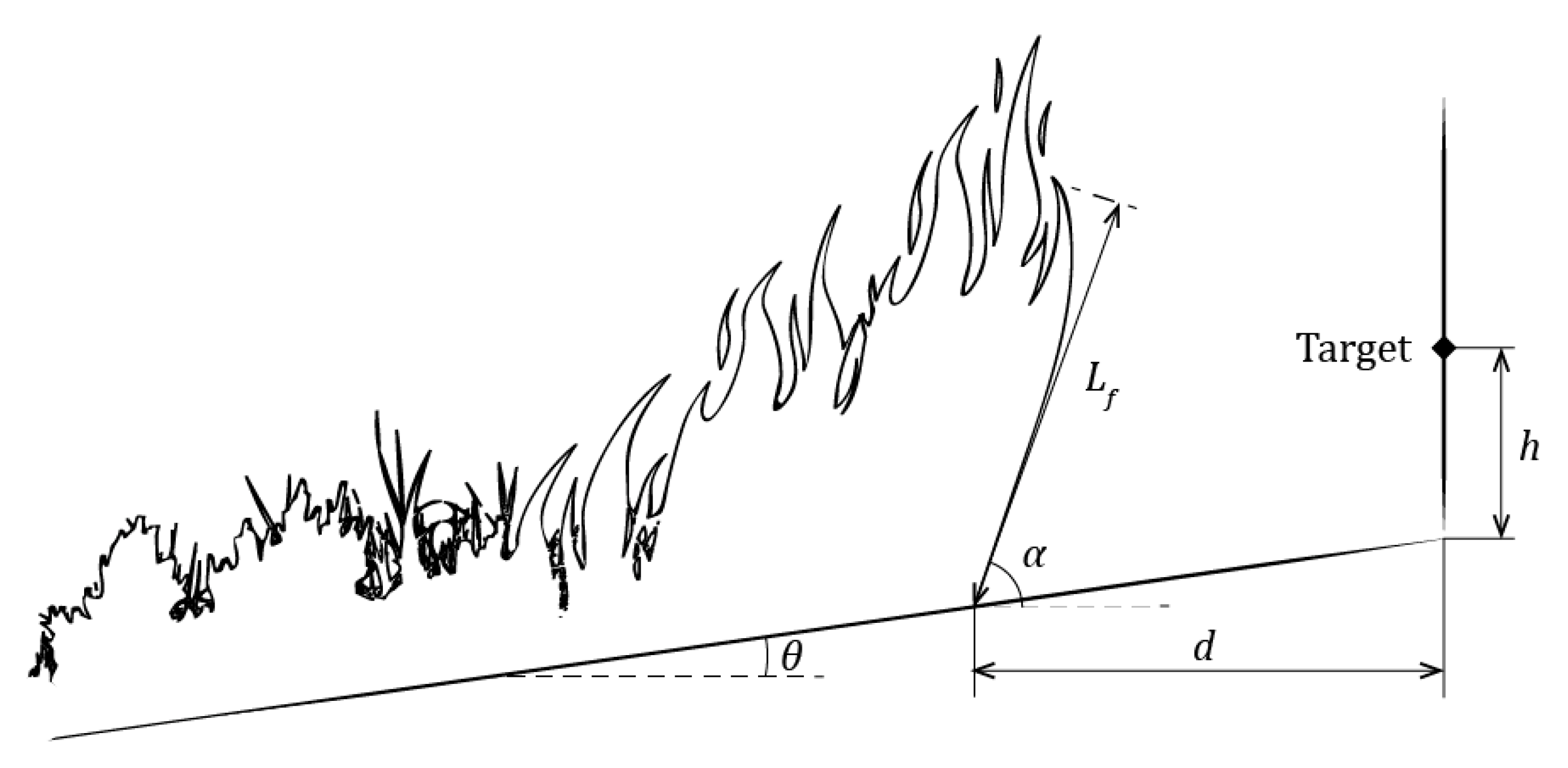
where ε is the emissivity (unitless), σ is the Stefan–Boltzmann constant equal to 5.67 × 10⁻⁸ W/(m2·K4) and Tf is the flame temperature (K). Figure 1 shows a schematic representation of the radiation model, where Wf and Hf are the width and height of the radiant surface (m) and d is the distance (m) to the receiving surface.
Emissivity (ε) of the flame can vary greatly and is difficult to calculate due to a complexity of fire process and multiple factors affecting it. These factors include fuel type and its moisture content, environmental conditions and the type of combustion. Moreover, daily fluctuations of weather conditions, such as temperature and humidity, directly affect the fuel moisture content. Thus, in real conditions during the burning process the parameters of flame do not remain constant. Emissivity also depends on flame dimensions. It was experimentally found that it increases with increasing thickness, or diameter of flames [21,22,23] and may reach its maximum possible value of 1. Bushfire models assume that flames are uniform black bodies and have an emissivity of 1 (maximum value of this parameter), which is an assumption for large wildland fires, namely in condition where the flames are more than 3 m in depth (flame thickness) [18].
Atmospheric transmissivity (τ) is a parameter that takes into account the effect of absorption of radiation by surrounding atmosphere (by water vapor and carbon dioxide) and scattering along the path (distance between fire and receiving surface) [13]. It is unitless and varies between 0 and 1. In modelling of heat flux from flames transmissivity is often neglected due to a small effect at small distances [24]. For this study this parameter is taken as unity, which is a reasonable assumption.
Shape factor (F) for the solid planar surface model is calculated for the geometry of the vertical surface and the distance at which the target is located from the emitting surface. For this research the target is placed at half of the height of the radiant surface (Figure 1). From the critical incident heat flux of 12.5 kW/m2 and all the necessary dimensions, d12.5 can be obtained. Flames are presented as a rectangular panel emitting heat, and a building facade as a receiving target. Therefore, the geometrical parameters of the flame, such as the flame length and width, are necessary for the determination of the incident heat flux. The flame width can be assumed. The length of flame depends on many factors, such as physical and chemical parameters of the fuel and the environmental conditions. Considering that green roofs vegetation can vary greatly from simple grass cover to roof gardens, in case of fire the flames produced will also vary and will determine qrad to adjacent surfaces. For this reason, it is important to determine the flame lengths produced by different types of vegetation for the accurate calculation of qrad. The expression for calculating F is presented further.
Geometrical parameters of flames in wildfires can be found in previous experimental studies. Several field tests were conducted in Australia [25,26], Brazil [27] and Europe [28,29,30]. Data from small-scale laboratory measurements is also available for litter fuel [31,32,33]. However, since fires were performed on natural landscapes, the results obtained in each study are for specific environmental conditions and fuel parameters.

2.2. Fire Behavior Models

It is also possible to obtain fire front parameters from mathematical fire behavior models, such as Catchpole, Bradstock [34] and Cruz, Matthews [35] for shrublands in Australia, Noble, Gill [36] and Cheney, Gould [37] for grasslands, and the model of Rothermel [38], developed generally for uniform wildlands. Based on theoretical predictions and on observation data such models were elaborated for prediction of fire spread during wildfires that allow to roughly estimate other flame characteristics. The rate of spread of fire (RoS) determines fire intensity (I) and the length of flame, Lf. The length of flame is the distance between the midpoint of the base of the flaming zone and the flame tip, which is equal to Hf for non-inclined flames on a flat surface [39]. Models require different physical and chemical characteristics of vegetation, and environmental conditions, such as wind speed and slope.
Australian standard AS3959 Method 2 [40] estimates the fire risk level for construction in bushfire-prone areas in Australia. In Bushfire behavior model requires input parameters such as fire danger index according to the region or wind speed, fuel characteristics (vegetation classification, fuel load and fuel height) and measured parameters of the site (slope, distance to vegetation). This Australian standard was developed specifically for wildfires, assuming that the fire is developed, and its spread reached a quasi-steady-state condition. The vegetation cover is assumed continuous and homogenous. Wind speed is constant. Also, the assessment fire area is equal to 1 ha (100 × 100 m), which means that Wf is equal to 100 m. This is the main limitation for using this standard for fires that are smaller and not fully developed.
To analyze smaller fire areas Penney [41] described a method that introduces the modifications to available fuel load and area. Reduced fuel load density and a new geometry of the vegetation fuel bed prevents the fire attaining its maximum potential rate of spread. This model, however, can underestimate fire parameters and the emitted heat flux. It is mentioned that the proposed improvement, which is the estimation of RoS as that of accelerating fire from a point source [42] rather than developed steady-state fire spread, is not suitable for grasslands and shrublands, because the fire can reach steady state in a shorter period than in treed vegetation.
Another method to assess fire risk from vegetation covering small areas, where fire is not fully developed, is the short fire run (SFR) model. This method follows the standard AS3959, introducing the determination of the Wf. The example of Delany, Boverman [43] shows that due to a smaller Wf the resultant heat flux was 56% smaller than that obtained by the standard method of AS3959. It is noted by Penney [41] that the model’s assumption that the RoS of fire is the same as that of a fully developed fire can be conservative.
Another mathematical surface fire behavior model was described by Rothermel [38], which is used in National Fire Danger Rating System (NFDRS). The advantage of this model is its applicability to various types of wildlands found in North America. Required inputs parameters include topography data (slope), environmental conditions (fuel moisture and wind speed) and a set of fuel characteristics. These are factors that have the greatest impact on fire behavior and thus careful selection of these parameters is critical for the reliability of results. As with the Australian model, the limitation of this model is its applicability to steadily propagating fire in uniform homogenous fuel beds and stable environment independent of time and space. Rate of spread can be determined with Equation (9).
R o S = I r ξ 1 + Φ W + Φ S ρ b ε Q ig
where RoS is the rate of spread (m/min), Ir is the reaction intensity (kJ/(min·m2)), ξ is the propagating flux ratio, ɸW is the wind coefficient, ɸS is the slope factor, ρb is the ovendry bulk density (kg/m3), ε is the effective heating number and Qig is the heat of pre-ignition (kJ/kg).
Rate of spread is then used to determine fire intensity and the length of flame Lf. Both characteristics are computed using Byram’s equations modified by Wilson [44] for SI units:
I = 1 60 I r R o S 12.6 s a / v o l
where sa/vol is surface area to volume ratio of the fuel bed (m−1).
L f = 0.0775 · I 0.46
Application of this model is simplified by categorizing fuels into separate groups (fuel models) with a set of specific parameters as inputs that represent typical field conditions. Quick estimation of fire parameters according to Rothermel’s model can be made numerically using modelling tools, such as the BehavePlus Fire Modeling System [45]. It includes the original 13 fuel models by Albini [46], and 40 refined fuel models by Scott and Burgan [47] that allow for more flexibility in characterizing the fuel bed and more precise predictions.
Possible fires on green roofs are expected to be less intense than wildfires due to smaller areas necessary to develop steady-state fire. However, due to the lack of information on fire behavior modelling specifically for urban environment and to a number of factors affecting small fires it is difficult to make exact predictions or rely on existing experimental data on combustion characteristics of several plants or vegetation. Thus, for this research the prediction of flame length was performed with the existing fire behavior model. Even though the results can be very conservative, it can help to analyze most hazardous situations. The surface fire spread model of Rothermel [38] was chosen due to its applicability for all types of wildland and the possibility to choose more precisely the fuel type models that were developed for vegetation in North American climate. The determination of flame length was performed using BehavePlus 6.0.0 Beta 3 (USA, 2018) [48]. The parameters for modelling are described in the next section.

2.3. Parameters

Main parameters to set for fire behavior models for this study are fuel models, which is to associate green roof vegetation with certain types of wildlands, and weather conditions, such as fuel moisture content and wind speed. It is assumed that the surface is flat, thus for the topography parameter, the site slope θ is equal to 0.

2.3.1. Vegetation Types (Fuel Models)

It is possible to install a great variety of plants on roofs, from grasses to trees. However, it is generally considered that short vegetation of less than 10 cm, as well as maintained gardens and parklands, do not present a fire risk due to insufficient fuel to support fire propagation [40]. Therefore, in this study only 3 categories (types) of fuel models were taken for calculations: grasslands (GR), shrublands (SH) and grass-shrub mixed wildlands (GS). Three models in each category were chosen according to three main parameters, specifically fuel load, vegetation height (fuel bed depth) and density of vegetation cover (by description). Other parameters, such as moisture of extinction, packing ratio and surface-area-to-volume ratio were not considered. However, these characteristics can affect the results. Table 1 lists fuel models chosen and their parameters. It must be noted that, typically, vegetation cover on green roofs does not present dense stands. Thus, GR-2, GS-1 and SH-2 are more representative for green roofs. Other models were taken to cover a greater variety of green roof vegetation.
Grasses are thin fuels that easily support fire spread at favorable moisture conditions, producing large flames, increasing in length with increasing fuel load and height. GR-2 is a low grass with a small fuel load. The other two grass models are twice as high and with larger fuel loads. GR-2 and GR-4 models are dry climate grasses, while GR-3 is from a humid climate. This determines the moisture of extinction percentage, being 15% and 30–40% for given dry climate and humid climate fuel models, respectively [47]. This parameter shows a state at which fire does not spread. GS models present a wildland where both grasses and small shrubs can be found. GS-1 contains very low shrubs and small grass fuel load, while GS-2 and GS-3 contain twice higher shrubs and moderate grass loads. GS-1 and GS-2 are dry climate models and GS-3 is a humid climate model. Finally, shrubs are models with no or very small grass load and shrubs occupy at least 50% of area. SH-2 is a dry-climate vegetation with very low shrubs, while the other shrubs models’ vegetation height is 3 times greater. For Grass-shrub and Shrub types, flame lengths are expected to be from low (GS-1, SH-2) to high (GS-4, SH-8) with increasing fuel load, vegetation height and density. It must be noted that GR live fuel is only herbaceous, SH live fuel is only woody, while GS is a mix of herbaceous and woody parts. The composition greatly determines the fire behavior, due to different moisture content of each part, which is explained in the next section.

2.3.2. Moisture Content (MC)

Green roofs with intensive greening must be provided with sufficient irrigation to support plant life and are not supposed to dry out. It is expected that MC of vegetation will not drop to the lowest point. However, considering seasonal changes in weather and related naturally occurring drying process, which takes place in the end of summer and in autumn [49], it would be necessary to investigate the fire risk during this most fire hazardous period.
Fuel moisture content is an important parameter that greatly affects the availability of fuel in fire and determines the possibility and the rate of fire spread. For Rothermel [38] the fuel load is presented as a sum of separate fuel loads, such as dead and live, due to different moisture uptake and fluctuation processes for each of the group. Dead plant material MC is regulated mostly by the environment, while for the live part it changes with the season. Both fuels consist of categories according to plant material and size. Dead fuel consists of categories according to size of the particles: 1-, 10-, 100- and 1000-h time lag, which means the amount of time needed for a particle to reach equilibrium MC. Live fuel consists of herbaceous (foliage, grass) and woody parts (brush). Thus, for all categories MC is specified separately.
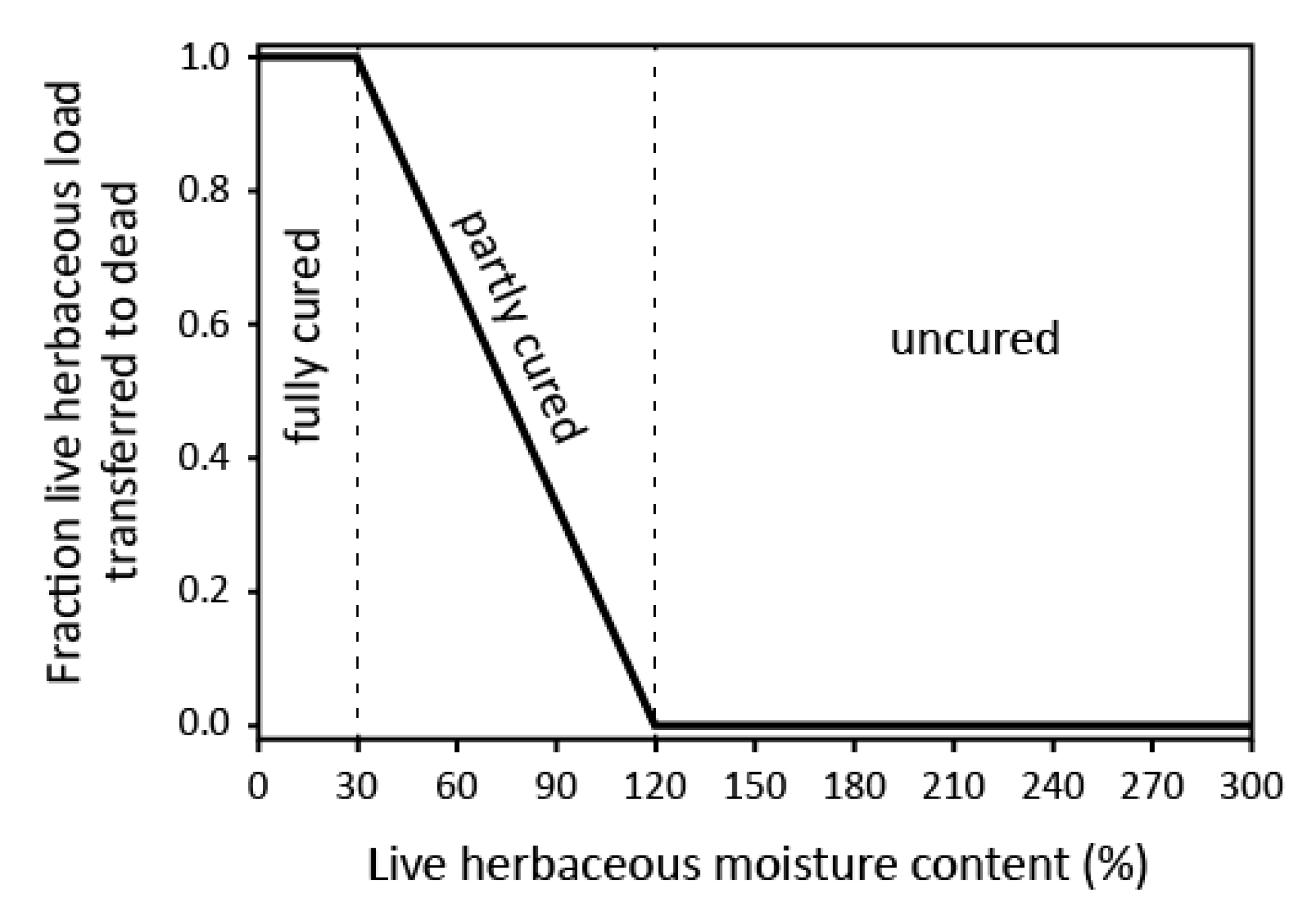
When MC of the herbaceous part decreases from 120 to 30%, the transition from live to dead material occurs. Once it drops to 30% the fuel is considered cured, or dead, which occurs in the end of summer, from the end of July [50]. In late spring and early summer plants produce new herbaceous material that contains more than 120% of MC and is considered green [49]. Such material acts as a heat sink, where spread of flame does not occur. Live woody material similarly undergoes seasonal changes in MC, however, with different percentages. Live woody fuel becomes dormant, or dead, when MC drops to 50% [50], and is considered fully green at 150% [47].
For grasses, that mostly consist of herbaceous fuel, moisture condition is usually characterized by a degree of curing, converted MC of live herbaceous into two parts, green fuel and dead (live fuel that became dead). Figure 2 shows the level of curing according to herbaceous MC.
In BehavePlus, models that contain herbaceous fuel are considered dynamic. This means that according to the MC of herbaceous fuel one part is transferred to a dead load and its moisture is set equal to a specified 1-h dead fuel load (Figure 2). Scott and Burgan [47] suggest standard MC of fuels in 16 combinations of moisture scenarios: very low (D1, L1), low (D2, L2), moderate (D3, L3) and high (D4, L4) for dead and live parts. In BehavePlus, these combinations are presented as default input options. For live woody fuels the values are of 60% (two thirds are cured), 90% (one third is cured), 120% (green) and 150% (green) MC, respectively. MCs of herbaceous fuel are 30, 60, 90 and 120% for each of the scenarios, respectively. Fuel MC scenarios are shown in Table 2.
In the present work only default combinations of dead and live fuels were used for each type of vegetation in order to compare the most and least hazardous cases. Moisture scenarios used in this study are given in Table 3.

2.3.3. Wind Speed

Wind greatly affects fire behavior and is an important component in fire spread models. It is known that windy conditions lead to increase in forward rate of spread and therefore to greater fire intensity and larger flames [49]. For this study mean daily values of wind speed in the city of Montreal (Canada) were taken for the period of May–October 2019 [51]. Figure 3 shows daily average values for the whole period with a mean value of 14.5 km/h and mean 25th and 75th percentiles of 9.7 and 18.1 km/h. Weekly average wind speed is shown as well. For this study, wind speed was considered constant in time. Wind speeds of 0, 5, 10, 20 km/h and the mean value of 15 km/h were taken for the analysis.
Using the Beaufort Wind Force Scale, wind of up to 5 km/h is characterized as light air, 10 km/h is considered a light breeze, causing leaves to rustle, 12–19 km/h is a gentle breeze, at which leaves and twigs are constantly moving, and 20 km/h is a moderate breeze, at which movement of small branches is observed [52].

2.3.4. Radiation Model Parameters

Equations (2) and (3) are used following several assumptions from the AS3959 standard. The emissivity (ε) is taken to be equal to 0.95 and the flame temperature is equal to 1090 K. Flame width (Wf) is set to 10 m assuming a medium-sized roof area covered by vegetation. The shape factor is obtained with the following equations from AS3959 [40]:
F = 1 π X 1 1 + X 1 2 tan 1 Y 1 1 + X 1 2 + Y 1 1 + Y 1 2 tan 1 X 1 1 + Y 1 2 + X 2 1 + X 2 2 tan 1 Y 2 1 + X 2 2 + Y 2 1 + Y 2 2 tan 1 X 2 1 + Y 2 2
where
X 1 = L f sin α 0.5 L f cos α tan θ d tan θ h d 0.5 L f cos α
X 2 = h + d 0.5 L f cos α tan θ d 0.5 L f cos α
Y 1 = Y 2 = 0.5 W f d 0.5 L f cos α
where Lf is the flame length (m), h is the elevation of the target (m) (equal to Lf/2), d is the distance to the target (m), Wf is the fire front width (m), α (°) is the flame inclination (flame angle or tilt) and θ is the site slope (°). The geometrical representation is shown in Figure 4. The flame angle α is equal to 90° and Hf is equal to Lf in no wind condition, where vertical flames are produced. In windy conditions, flames incline. The determination of the angle as a function of wind speed is very complex and produces great uncertainty in the results. Thus, α is determined with the algorithm proposed in the standard AS3959 according to the worst-case scenario to obtain maximum view factor. In other words, the goal is to obtain the maximum value of qrad, particularly, the greatest distance d at which 12.5 kW/m2 is reached (d12.5).
According to AS3959, the flame angle algorithm consists of the following steps:
  • Set the initial value for the angle (α0) and determination of the view factor (F0) with the Equations (6)–(9) in AS3959. The target height h is taken in the middle of Lf.
  • Set the increment for the angle (Δα) and maximum error allowed (°).
  • Calculate view factor (F1) for α1 which is equal to α0 + Δα.
  • Calculate view factor (F2) for α2 which is equal to α1 + Δα.
  • Comparison of obtained view factors. In case F1 >= F0 and F1 > F2, then check the error. If it is greater than the set value, then decrease Δα and repeat steps 3 and 4. In case F2 is greater than F0 and F1 then set new values: α0 is equal to α1, α1 is equal to α2, thus F0 becomes equal to F1, and F1 equal to F2. Then repeat steps 4 and 5.

3. Results

The heat flux emitted by burning vegetation was 75 kW/m2 based on the assumed parameters. From the results of flame lengths determined with BehavePlus for different fuel models and specified wind and moisture conditions the qrad were calculated. Cases where the flame lengths were less than 0.5 m were not considered. The results of qrad as a function of separation distance are presented for the average wind speed. The results of the analysis of the effect of wind speed and MC on d12.5 are presented for each moisture scenario and are grouped by the fuel type.

3.1. Radiative Heat Flux

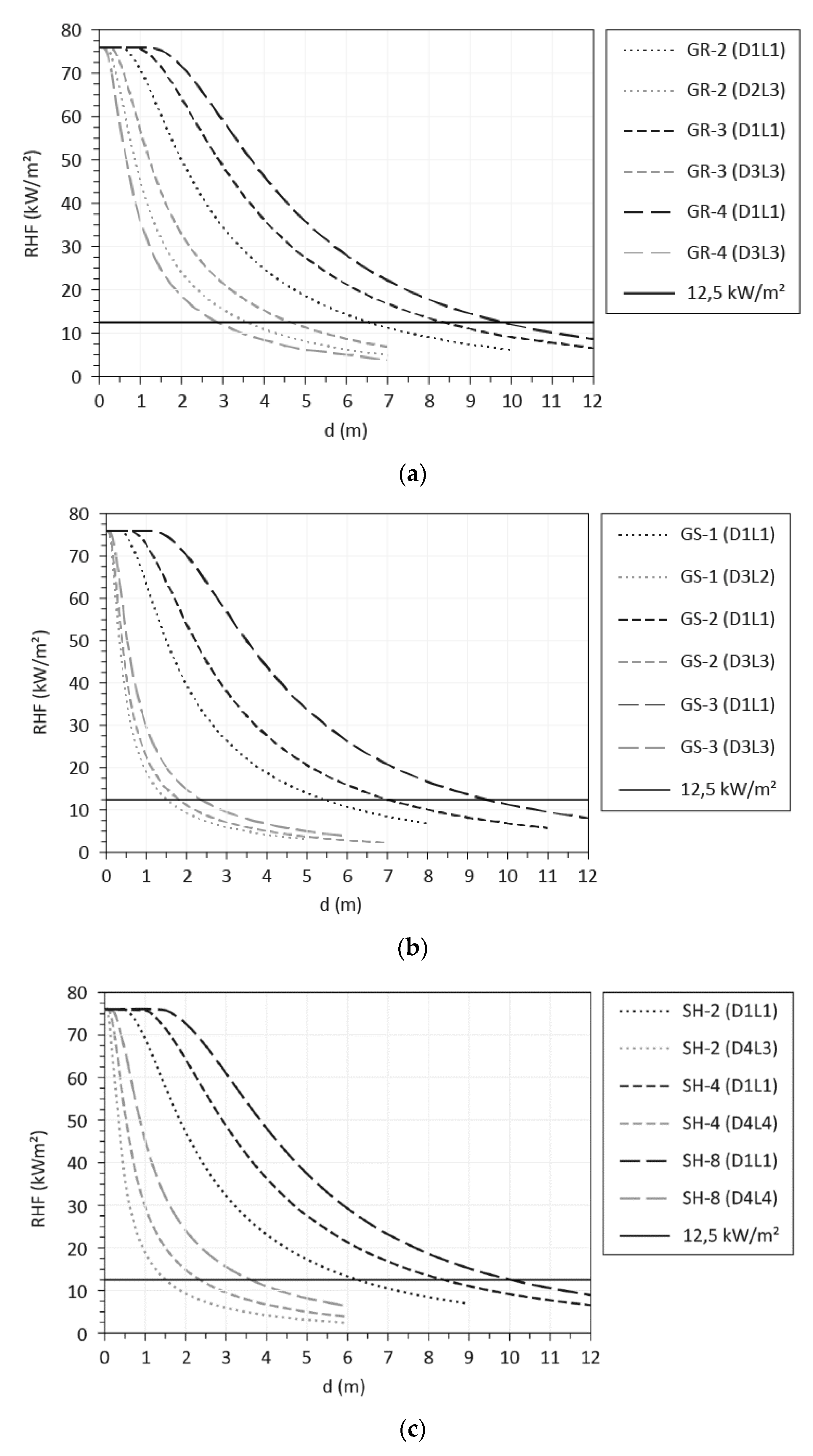
The qrad for daily average wind condition of 15 km/h is presented in Figure 5 for each fuel category at most hazardous moisture condition (D1L1). Results at moisture scenarios at which flames of the smallest length are produced (but not less than 0.5 m) are presented as well for the comparison of the most and the least hazardous cases.
Considering that a critical level of heat flux is equal to 12.5 kW/m2 (horizontal line on the graph), the graph presents the separation distance ranges for each fuel model. For GR category models GR-3 and GR-4 the smallest flames were produced at moderate moisture condition for dead and live loads, while for GR-2 flames were not presented at this moisture scenario due to the small load and height of the vegetation. The smallest flames of 1.3 m were obtained where dead load was at low MC and live load at moderate MC (D2L3). d12.5 at the most hazardous condition was 6.6 m for GR-2, 8.4 m for GR-3 and 9.8 m for GR-4. At moderate moisture contents d12.5 was reduced to more than one third for GR-4 (2.9 m) and almost half for GR-2 and GR-3 (3.6 and 4.7 m).
Grass-Shrub models show almost the same results for d12.5 at very low MC, which were 6.5, 7.0 and 9.5 m for GS-1, GS-2 and GS-3 models, respectively. At moderate moisture conditions, a 2.4 m separation zone was sufficient for all fuel models.
Results of d12.5 for the SH models were the same as for the GR models at very low MC, which were 6.3, 8.4 and 10 m for SH-2, SH-4 and SH-8, respectively. However, the smallest flame lengths were obtained when both dead and live loads were at high MC for SH-4 and SH-8. For SH-2 flame length of 0.5 m were obtained at dead load at high MC and live load at moderate MC (D4L3). The smallest d12.5 are thus between 1.8 and 3.6 m.

3.2. Wind and Moisture Effect

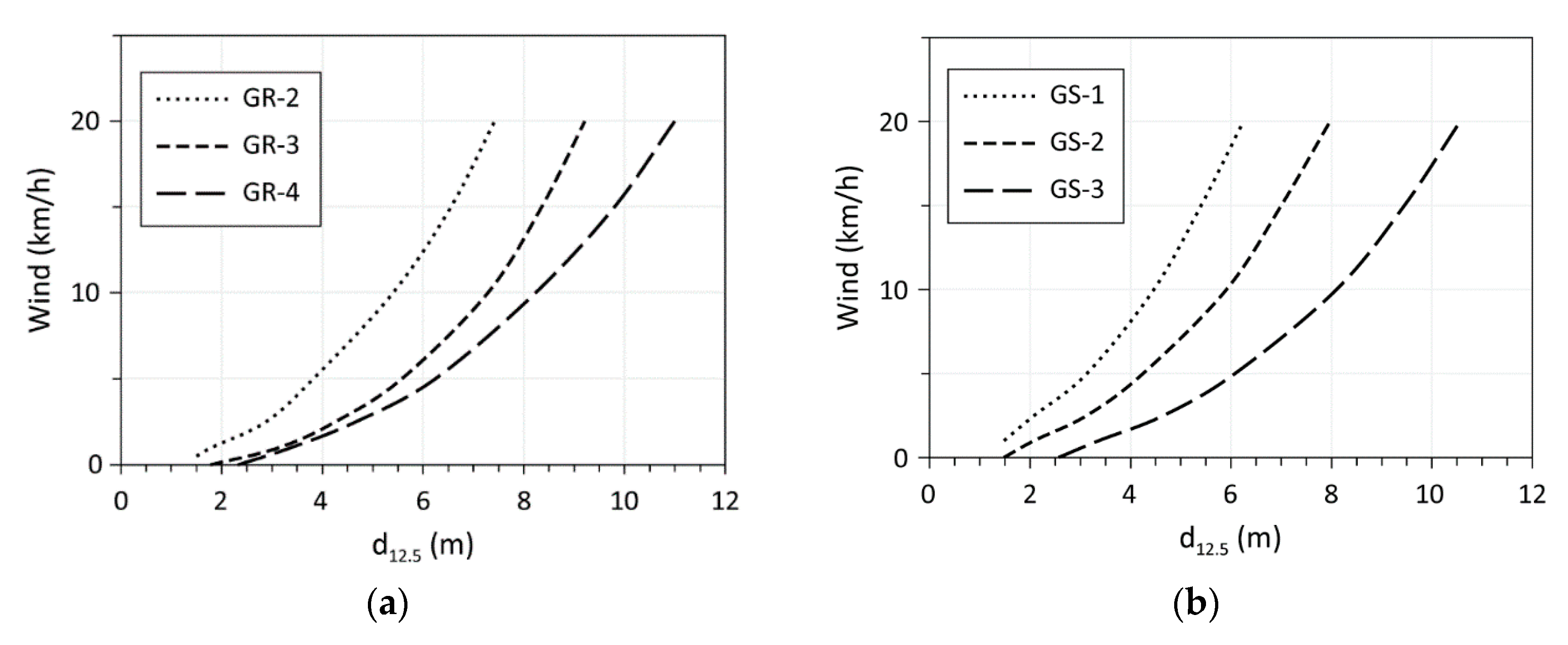
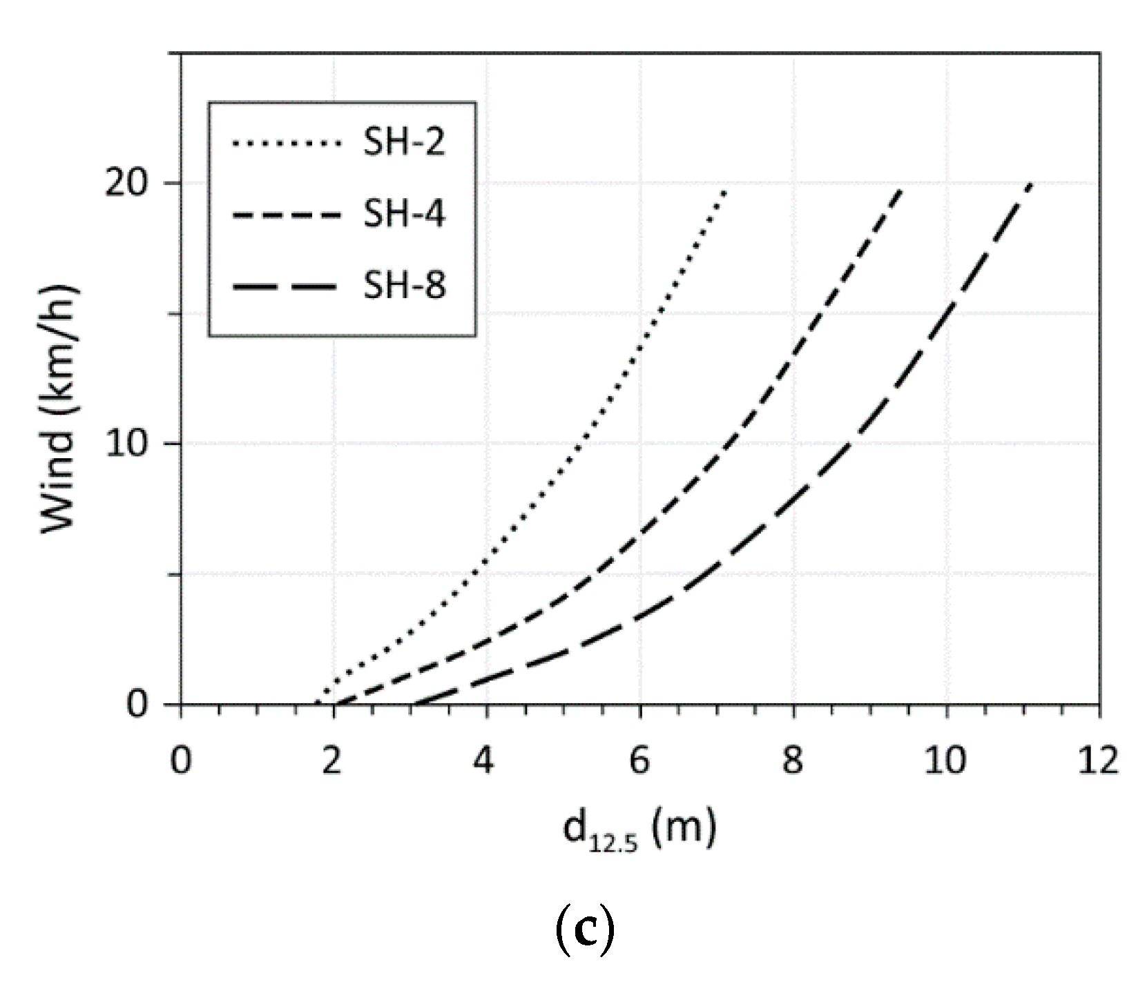
Wind has a strong effect on the flame spread since it provides greater oxygen supply to a burning fuel which increases burning rate. It also causes flames to incline to the unburned vegetation, which thus becomes exposed to greater radiation and convection heat fluxes [53]. Consequently, fire intensity and flame length increase. Figure 6a–c presents the effect of wind speed on d12.5 for D1L1 scenario.
This scenario represents very dry atmospheric conditions, when lack of precipitations for a long period and/or increased solar radiation leads to reduced MC of dead fuel. The live fuel in its turn becomes dead or entering dormancy, which usually happens during drought or late-summer-early-autumn period. In Figure 6 the curves present condition at which the qrad is 12.5 kW/m2. In the absence of wind, d12.5 for all vegetation categories does not exceed 3 m, specifically 2 m for grasses, 2.5 m for grass-shrub vegetation and 3 m for shrubs. Under windy conditions, flame lengths substantially increase even at low winds, requiring much greater separation zones from the vegetation. For example, at only 5 km/h flames of GR fuel models become more than three times longer, from 0.4 to 1.4 m for GR-2, from 0.6 to 2.3 m for GR-3 and from 0.8 to 2.7 m for GR-4. This leads to an increase of d12.5 of more than 2.5 times, from 1.5 to 3.8 m for GR-2, from 1.8 to 5.6 for GR-3 and from 2.3 to 6.2 m for GR-4.
With strong winds larger flames are produced. Wind speeds of 20 km/h result in flames of 3.5, 4.9 and 6.5 m for GR-2, GR-3 and GR-4 models, respectively, and therefore d12.5 increases to 7.4, 9.2 and 11 m for the same fuel models. With increasing wind speed, however, its effect is slightly reduced, while the effect of fuel load and height become much more pronounced compared to no-wind condition. For GS and SH categories the same behavior is observed, with smaller results for GS-1 compared to other low-load fuel models, which is explained by the difference in proportions of dead and live fuel loads as well as the presence of both herbaceous and woody parts in live fuel. GS-1 is composed of a small amount of dead fuel compared to SH-2, and a smaller amount of herbaceous fuel compared to GR-2, which are the main contributors to fire for these models (Table 1). Also, GR curves are slightly more inclined. Increased wind effect is explained by the structure of the fuel. Grass particles are of small diameters, have high surface area-to-volume ratio and low bulk density of the fuel bed, which allows them to burn at high rates and which is more noticeable at high winds.
Less fire hazardous conditions when plants have higher MC were analyzed and presented in Figure 7, Figure 8, Figure 9, Figure 10, Figure 11, Figure 12, Figure 13, Figure 14, Figure 15 and Figure 16 for each moisture scenario. The effect of environmental condition, expressed through the variation of MC of dead fuel, is presented as well.
Figure 7, Figure 8, Figure 9, Figure 10, Figure 11 and Figure 12 present d12.5 as a function of wind speed for D2L2 scenario. Such conditions can be expected in the middle or end of summer season. Two times higher MC of herbaceous and fine dead fuels (Table 2) leads to smaller flame lengths, being about two thirds the size of flames for D1L1 condition, at all wind speeds. The exception is for the SH-2 model, for which flame lengths are almost one third of the size of flames at the extremely dry condition. This is because SH-2 represents low-growing shrubs with average fuel bed depth of only 0.3 m, and thus plant height does not contribute to the development of flame size. The size of separation zones for all models are smaller accordingly to the flame lengths.
For GR category flame lengths vary between 0 and 2.4 for low grasses (GR-2) and between 0.6 and 4.8 m for taller grass cover with greater fuel load (GR-4) for a given range of wind speeds. Calculated d12.5 for this fuel category is shown in Figure 7. The curves presenting results for each model are less steep compared to those obtained for extremely dry state (Figure 6a). d12.5 for all models decreased by at least 1 m in the presence of wind. For example, low grasses require a separation zone of 2.9 m, while at very low MC it must be 3.8 m at a wind speed of 5 km/h, and 5.8 m compared to 7.4 m at a wind speed of 20 km/h.
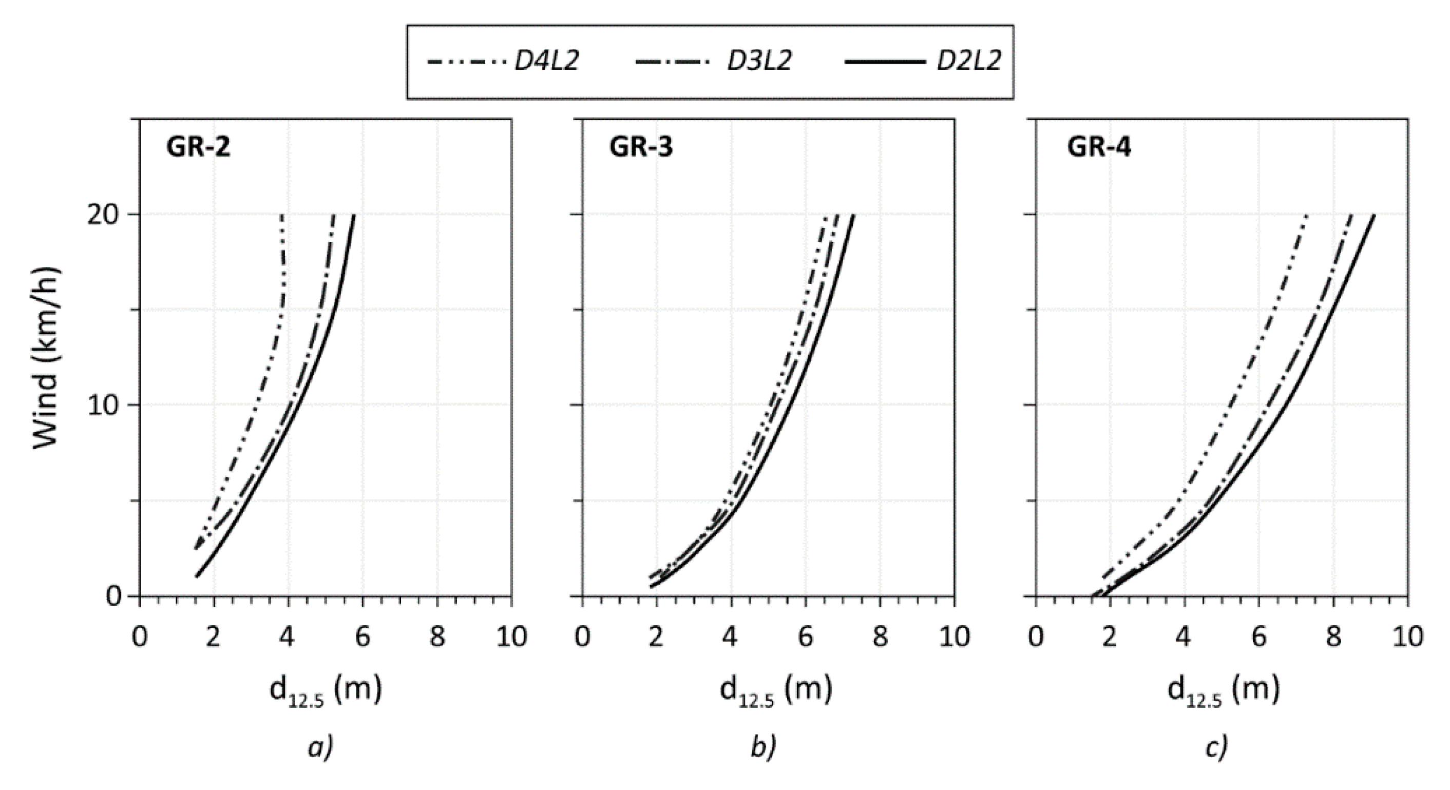
To assess the effect of weather conditions, which is reflected in changes of MC of fine dead fuel, the results of D2L2 scenario were compared to results obtained for conditions with more elevated humidity of dead part. Since the primary contributor to fire for grasses is live herbaceous fuel and the dead fuel load is very low, variable MC of dead fuel does not remarkably affect the results of fire behavior and radiation models. This can be observed in Figure 8a–c showing d12.5 as functions of the wind speed for each of GR model at three moisture scenarios (D2L2, D3L2, D4L2). Results of models with dead fuel moisture at low (D2) and moderate (D3) states are nearly similar at wind speeds of up to 15 km/h. Higher MC (D4) allows to reduce the separation zone for about 1 m at a wind speed of 10 km/h and 2 m at 20 km/h.
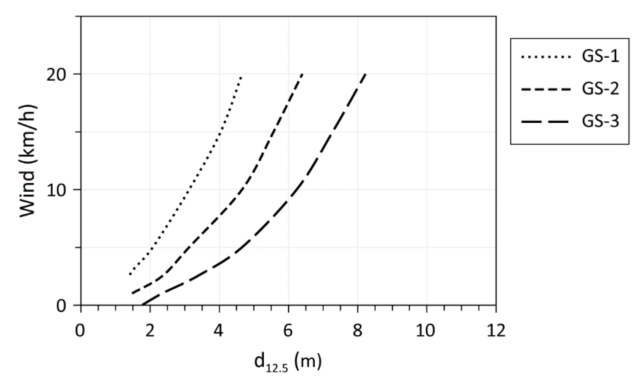
For GS and SH categories, the same analyses were performed. Figure 9 shows the dependence of the d12.5 on the wind speed for GS models for D2L2 scenario. Flames reached 1.8 m for low fuel load model GS-1, and 4.1 m for GS-3. Compared to the results of the D1L1 scenario, the possible reduction of separation zones was by 1.3 m at 10 km/h and by 1.6 at 20 km/h for the GS-1 and GS-2 models. For the GS-4 model the separation zone was at least 2 m smaller at 10 km/h, and 2.3 m smaller at 20 km/h.
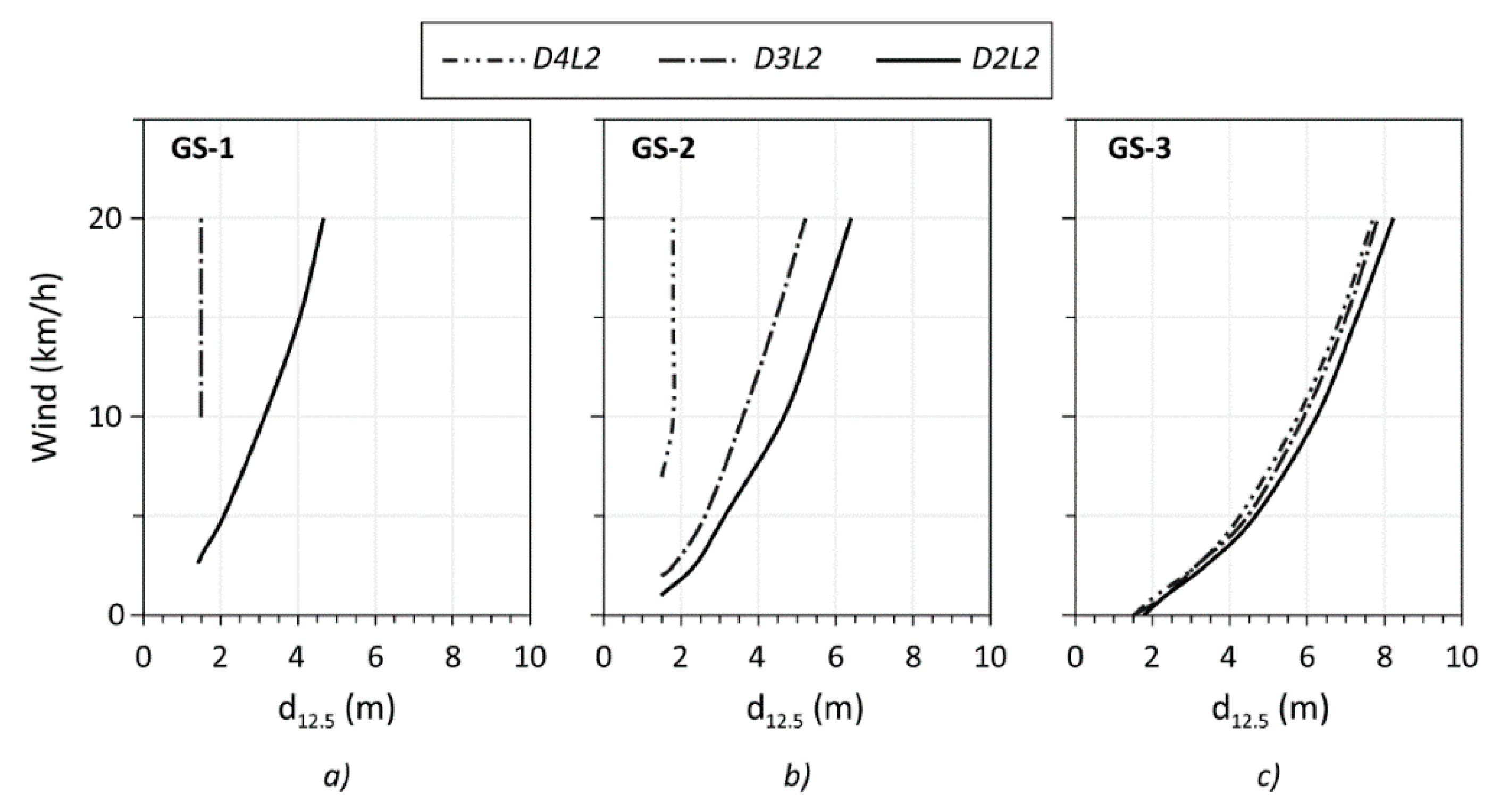
The weather effect for the GS category is presented in Figure 10. GS models have different proportions of dead, live herbaceous and live woody fuel, and therefore, the variation of dead fuel MC had a different effect on the results. For GS-1 at D4L2 flames were not observed. This can be explained by its fuel proportions, and the modelling method. Both herbaceous and dead fuel loads are very low, and because this is a dynamic fuel model, a big portion of herbaceous fuel is transferred to dead and its MC is set to 12%, the same as for 1-h dead fuel. This MC is close to the moisture of extinction presumed in this model. Therefore, such vegetation does not effectively support fire. On the contrary, the GS-3 model has a fuel bed twice as deep as GS-1, its herbaceous fuel load is three times greater and the dead fuel moisture of extinction is 40%. These parameters allow such vegetation to support fire independently of weather conditions at the given range of dead MC, provided that the live fuel is at 60% of moisture (Figure 10c).
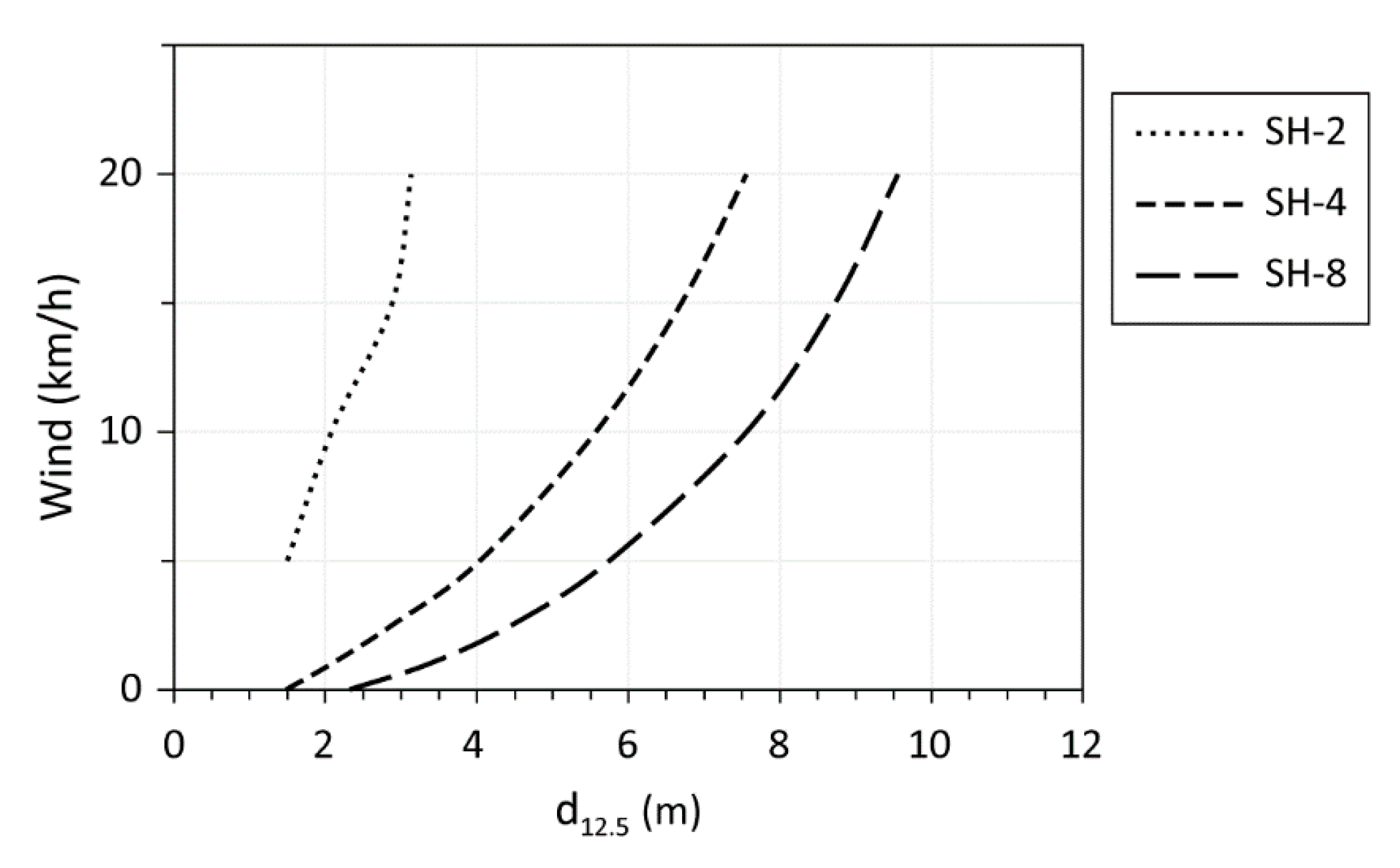
Results for d12.5 for the SH category at D2L2 scenario are shown in Figure 11. The SH-2 model, as mentioned above, consists of low-growing shrubs which make this model quite sensitive to moisture changes. This is reflected in a relatively small d12.5, which is 3.1 m at 20 km/h. For the other SH models, similarly to the GR and GS categories, required separation zones can be reduced by at least 1 m. Specifically, for SH-4 d12.5 is 5.6 m at 10 km/h and 7.6 m at 20 km/h, and for SH-8 it is 7.6 and 9.6 for the same wind speeds, respectively.
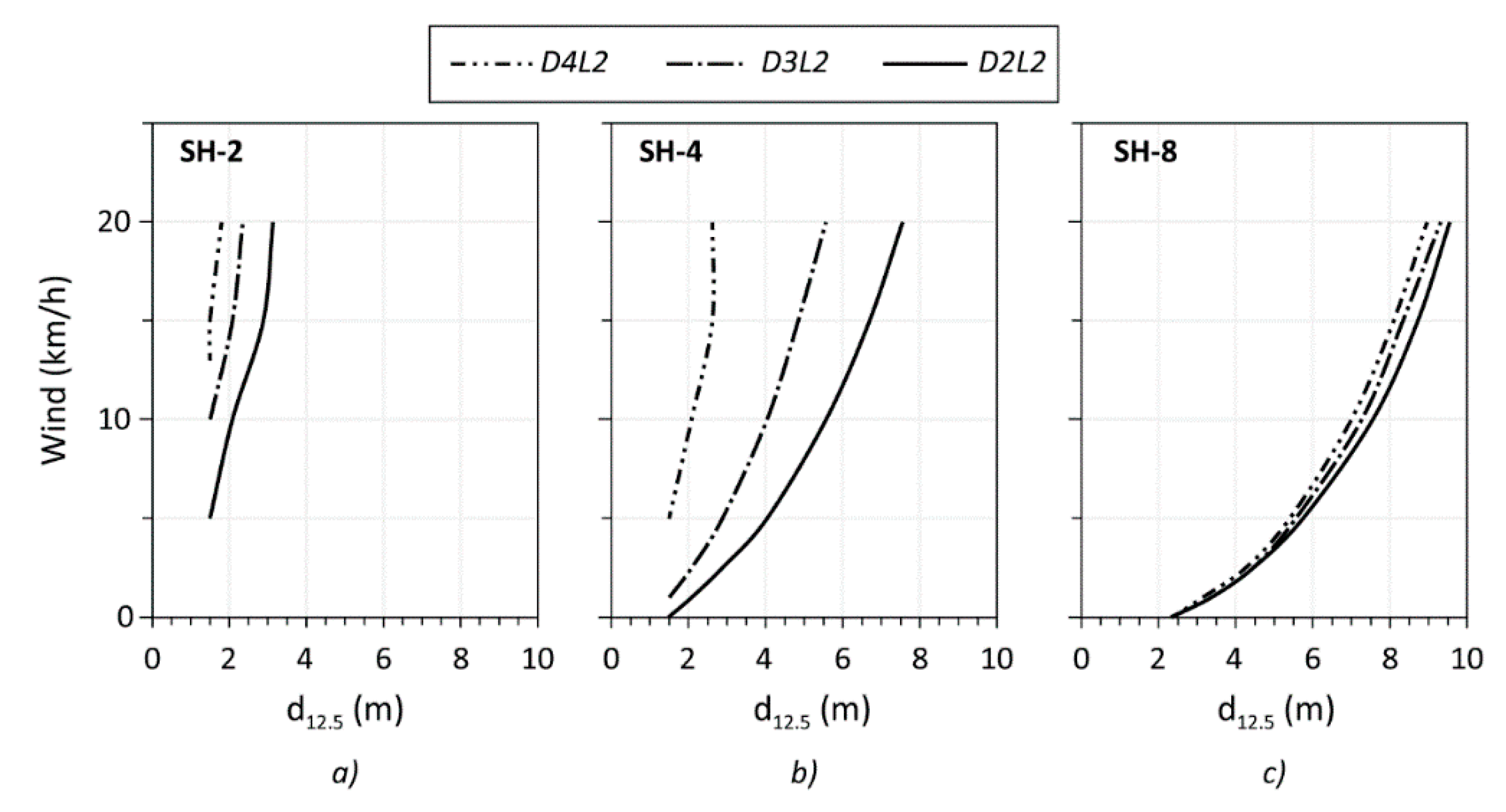
All SH models are not dynamic, since no herbaceous fuel is present. Therefore, the atmospheric condition effect depends directly on the amount of dead fuel and fuel bed depth. However, not all models show such behavior (Figure 12a–c). The SH-8 model presents dense shrub cover with fuel bed depth similar to that of SH-4, but with higher fuel load. The graph shows very small effect of variation of dead MC on fire behavior and thus on d12.5 at any wind speed. This can be explained by the difference in packing ratio of these fuels, 0.00227 for SH-4 and 0.00509 for SH-8 [47]. This parameter for the SH-8 model is probably closer to its optimum value that allows the fire to propagate more effectively and being less dependent on MC. The SH-4 model is quite responsive to the variations of dead fuel moisture. Flames become greatly smaller with increasing dead moisture, which allows for shorter distance of separation zones. For D4L2 scenario d12.5 can be reduced by 3.5 m at 10 km/h and by 5 m at 20 km/h compared to D2L2.
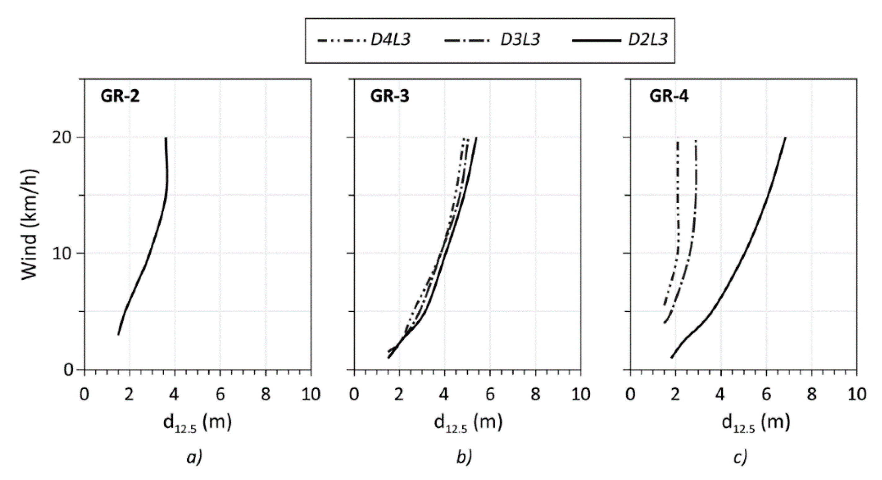
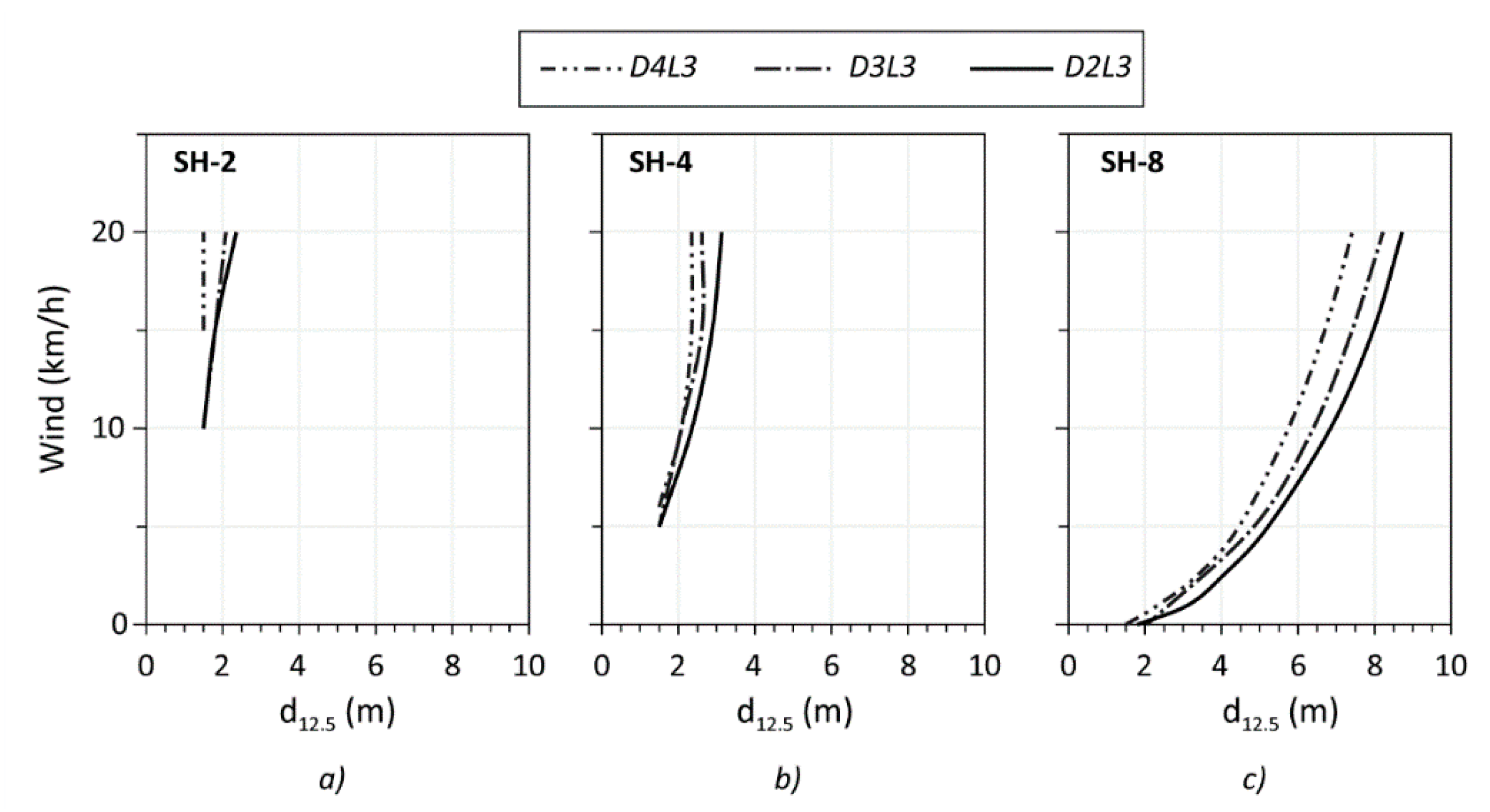
The results for the higher moisture scenario (D3L3) are presented in Figure 13, Figure 14 and Figure 15. Moderate moisture condition is observed at maturity of live fuels. Grasses at this stage are 1/3 cured and have a green color with noticeable yellow inclusions, which is considered end of green phase. At this stage vegetation presents low fire hazard. Figure 13 shows that GR-2 does not support fire, due to the low fuel load. In GR-3 and GR-4, taller and heavier grasses, some short flames can be observed, of maximum 2 m for GR-3 and 1 m for GR-4. d12.5 at highest winds for GR-3 is 5 m and for GR-4 is 2.9 m. Under calm conditions d12.5 of 1.5 m is sufficient to prevent the fire attack by thermal radiation. Variations of MC of dead fuel show that GR-3 is not sensitive to such changes, while GR-4 on the contrary is sensitive, especially when MC is low. Greater quantity of dead fuel leads to increased d12.5 in cases when ambient conditions are dry, leading to drying out of dead fuels.
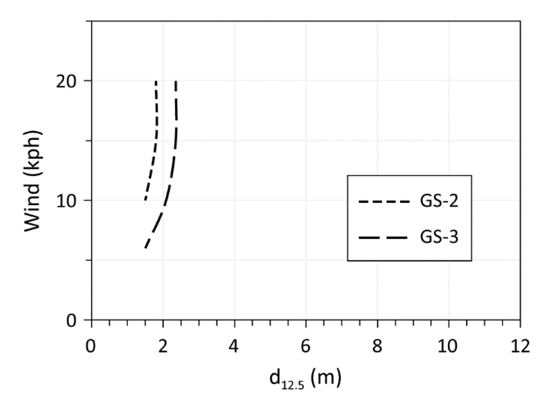
Smaller amount of herbaceous fuel in the GS category makes the vegetation less capable of supporting the fire at moderate moisture condition. Figure 14 presents the results of d12.5 for GS-2 and GS-3 categories only. Flame reached a maximum of 0.8 m in the presence of wind. Therefore, separation zone of 2.4 m is enough to provide safety. In case dead fuel MC drops to low values, only small changes occur. Flame size increases to 1 m, requiring d12.5 to be increased to 2.9 m (results not shown).
Results on SH behavior are shown in Figure 15 comparing three moisture scenarios with live fuel at moderate MC. Generally, this vegetation category produced flames of almost same size as other categories. Specifically, the lengths of flames were slightly smaller than those of GR and slightly larger than flames of GS. The exception is for the SH-8, where flames reached 4.1 m at 20 km/h. The variation of dead fuel MC has relatively small effect on fire behavior of all shrub models. SH-2 and SH-4 models present low fire risk at such moisture scenario, requiring d12.5 of 3 m at high wind. The SH-8 model, however, presents higher fire risk, which is explained by its higher fuel load. d12.5 is 8.7 m for the D2L3 scenario and 7.4 for D4L3 at 20 km/h.
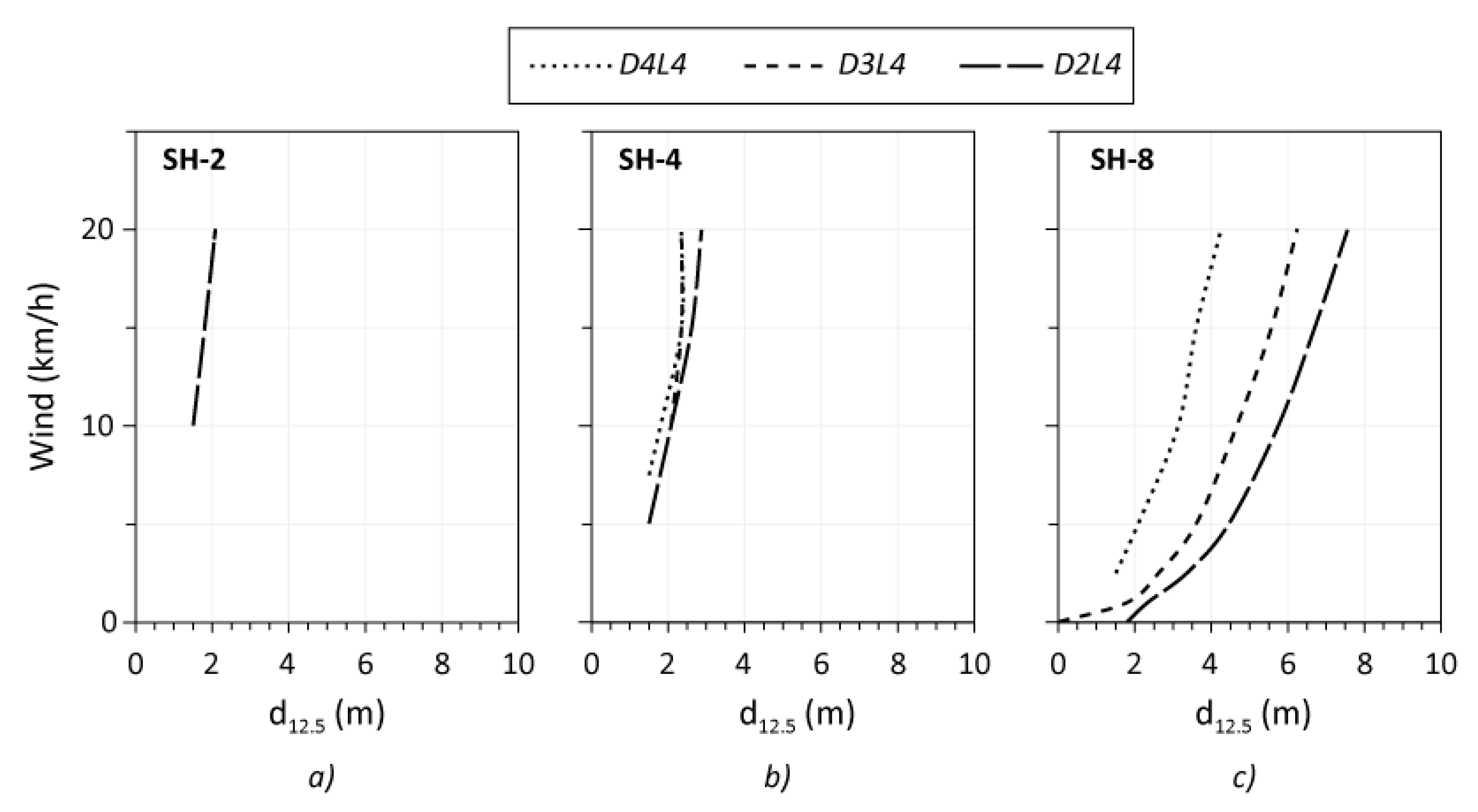
Finally, the least hazardous scenario D4L4 was analyzed. This scenario occurs in the spring–early-summer period with the apparition of new foliage and grass and the growth of new woody parts. Since in such conditions live fuel is considered green, the vegetation acts as a heat sink, and therefore no sustaining flaming can occur in models consisting mostly of herbaceous fuels, GR and GS. Figure 16 shows results of d12.5 for the SH category for the D4L4 scenario, as well as the D2L4 and D3L4 scenarios to assess the risk when dead fuel MC decreases.
It was seen that at low winds up to 5 km/h no flames were supported at D4L4. For SH-2 small flames of 0.5 m appeared only at 20 km/h, and for SH-4 at about 10 km/h. Maximum flame height reached by this fuel category was 0.8 m by SH-4 and 1.6 m by SH-8, requiring d12.5 of 2.4 m and 4 m, respectively. In case dead fuel dries out, scenario D2L4, the effect is visible for SH-2 and SH-8 models. Low shrubs (SH-2) support small flames of up to 0.7 m length at high winds. For dense shrub cover (SH-8) fire intensity greatly increases leading to flames of up to 3.6 m at 20 km/h and d12.5 of 7.6 m. Negligible effect was observed for SH-4 model.

4. Discussion

According to the results qrad rapidly decreases with distance for all types of vegetation (grasses, shrubs), especially for low-growing plants with low fuel load even at very low level of moisture content. This shows that the separation zone can greatly reduce the fire risk to adjacent buildings with combustible facades and can be considered when planning a green roof. However, it is important to consider factors that determine the minimum separation distance to facades, such as the vegetation characteristics, moisture content and wind speed. The analysis of d12.5 as a function of wind speed and moisture conditions for different vegetation types produced different results, showing the importance of each of these parameters and their effect. Each of the fuel categories and chosen fuel models (GR, GS, SH), despite presenting a relatively narrow range of parameters of fuel load and fuel bed depth, with maximum values of 1.6 kg/m2 and 0.9 m, have different capacities to support fire. Therefore, it is necessary to take into account the type of vegetation on the roof, due to the different fire risk it can present. Low grasses and shrubs that typically can be found on green roofs are not expected to support fire unless at low and very low moisture conditions and in the presence of wind. Considering that at least some moisture is usually present in vegetation, such as D2L2 scenario, d12.5 for short grass (GR-2) is 5.2 m, 4.0 m for grass-shrub mix (GS-1) and 2.9 for low shrubs (SH-2) at average wind speed of 15 km/h. Dense tall grasses and dense and heavy shrubs can produce much higher flames that require greater separation zones. For the same conditions, d12.5 is 8.0 m for tall grasses (GR-4), 7.3 m for grass-shrub mix (GS-3) and 8.8 m for dense tall shrubs (SH-8).
Large vegetation for green roofs is usually provided with permanent irrigation systems, not allowing them to die. Therefore, the D3L3 scenario, when live and dead fuels are at moderate MC, is more realistic. d12.5 decrease to 2.9 m for tall grasses (GR-4), 2.4 m for grass-shrub mix (GS-3) and 7.4 m for dense shrubs (SH-8) at 15 km/h when compared to the D2L2 moisture scenario. For all other fuel models with smaller fuel loads the effect is visible as well. These results show that the presence of moisture has a great effect on safety zones necessary to protect adjoining structures from exposure to thermal radiation produced by burning vegetation. Providing enough moisture level in plants can help to successfully control the fire hazard.
The presence of wind has a great influence on fire spread rate and size and therefore on d12.5. Compared to 15 km/h and D2L2 scenario, at 5 km/h, flame length greatly decreases and leads to much smaller d12.5 for all fuel models. For example, for tall and dense vegetation d12.5 decreases from 8 to 4.9 m for GR-4, from 7.3 to 4.7 for GS-3 and from 8.8 to 5.8 m for SH-8. For short and low fuel load vegetation its effect is even greater. Comparing the same scenarios and wind speeds, d12.5 decreases from 5.2 to 2.9 m for GR-2, from 4 to 2.1 m for GS-1 and from 2.9 to 1.5 m for SH-2. In the absence of wind, only small flames of 0.5–0.6 m with d12.5 of less than 2 m are observed and only for fuel models with high fuel loads in each category, such as GR-4, GS-3 and SH-4. For the SH-8 model a slightly greater d12.5 of 2.4 m is required. The effect of wind is greatly reduced at high moisture content of the vegetation. This analysis shows the importance of considering the wind speed that a roof is exposed to when assessing the fire risk and proposing safety measures.
It may seem that results in this study are quite severe. However, this is explained by the assumptions made. The values obtained are to be expected for steady-state fires. The limitations of roof area and time availability can prevent fire from reaching a fully developed state. It is also known that for fires with small combustion rates, such as at the developing stage, the wind effect is not proportional to its speed and can be much lower [49]. Therefore, results of the analysis in this study can serve as an example of extremely hazardous cases and a confirmation of the importance of the presence of moisture in green roofs especially with intensive greening for the reduction of fire risk for adjacent building.

5. Conclusions

This study assesses the risk of possible fire hazard from green roofs to adjoining structures when exposed to radiant heat. The separation distances to radiation heat exposure were obtained for different moisture and wind conditions and compared. A range of types of vegetation that can be found on green roofs was considered.
Low MC of dead load, that is present in moderate and high amount in shrubs, greatly increases fire risk. This can be regulated by creating a more humid environment by irrigation, and, if possible, less exposure to solar radiation by providing some shading, as well as less wind exposure. This is especially important for dry climates with low precipitations and drought periods. Irrigation also can retard the curing process, which is particularly important for grasses that mostly consist of live fuel. Therefore, presence of moisture is a primary essential parameter in protection from fire spread and thus the risk of radiation attack of the adjoining structures. Providing an irrigation system for tall plants and the vegetation presenting moderate or high fuel load is a simple solution.
Removal of dead plant material, when possible, also helps to reduce fire risk by reduction of fuel load. This is specifically important during most fire hazardous periods, like autumn, when live load becomes dead or plants become dormant.
Due to the method chosen, the results of the study are conservative and most likely overpredicted the calculated separation distances. However, they can be regarded as results of extreme conditions and point out the parameters that are necessary to consider when planning and maintaining green roof, such as vegetation type and height, wind exposure and moisture conditions.
To investigate fire effect on adjacent buildings in less idealized conditions, fire behavior models for limited vegetation areas need to be developed. A series of large-scale tests for different vegetation simulating roof conditions could confirm the modeling effort.

Author Contributions

Conceptualization, N.G., P.B. and C.D.; methodology, N.G.; validation, P.B., C.D. and N.G.; investigation, N.G.; resources, N.G.; writing—original draft preparation, N.G.; writing—review and editing, N.G., C.D., P.B., S.M. and J.C.; visualization, N.G.; supervision, P.B. and C.D.; funding acquisition, P.B. All authors have read and agreed to the published version of the manuscript.

Funding

The authors are grateful to Natural Sciences and Engineering Research Council of Canada for the financial support through its IRC and CRD programs (IRCPJ 461745-18 and RDCPJ 524504-18) as well as the industrial partners of the NSERC industrial chair on eco-responsible wood construction (CIRCERB).

Institutional Review Board Statement

Not applicable.

Informed Consent Statement

Not applicable.

Data Availability Statement

Not applicable.

Acknowledgments

The authors also acknowledge the Green Roof Working Group of the Green Building Council of Canada, Quebec’s section for technical data and mobility funding.

Conflicts of Interest

The authors declare no conflict of interest.

References

  1. Sutton, R.K. Green Roof Ecosystems; Springer International Publishing: Geneva, Switzerland, 2015; Volume 223, p. 447. [Google Scholar]
  2. Snodgrass, E.C.; McIntyre, L. The Green Roof Manual: A Professional Guide to Design, Installation, and Maintenance; Timber Press: Portland, OR, USA, 2010. [Google Scholar]
  3. Carlsson, E. External Fire Spread to Adjoining Buildings; Department of Fire Safety Engineering, Lund University: Lund, Sweden, 1999; pp. 1402–3504. [Google Scholar]
  4. Buchanan, A.H.; Abu, A.K. Fires and Heat. In Structural Design for Fire Safety; John Wiley & Sons, Ltd.: Hoboken, NJ, USA, 2017; pp. 35–83. [Google Scholar]
  5. RBQ. Critères Techniques Visant la Construction de Toits Végétalisés Quebec; Gouvernement du Québec: Québec, QC, Canada, 2015; pp. 15–16. [Google Scholar]
  6. ANSI/SPRI VF-1; External Fire Design Standard for Vegetative Roofs. American National Standards Institute/SPRI: Waltham, MA, USA, 2017.
  7. FM Global. Property Loss Prevention Data Sheet (1–35) Green Roof Systems; Factory Mutual Insurance Company: Johnston, RI, USA, 2011; pp. 1–27. [Google Scholar]
  8. FLL. Guidelines for the Planning, Construction and Maintenance of Green Roofing–Green Roofing Guideline. In Fire Characteristics; FLL (Forschungsgesellschaft Landschaftsentwicklung Landschaftsbau), Research Society for Landscape Development and Landscape Construction: Bonn, Germany, 2008; p. 36. [Google Scholar]
  9. Torvi, D.A.; Kashef, A.; Benichou, N. FIERAsystem Radiation to Adjacent Buildings Model (RABM) Theory Report; Institute for Research in Construction, National Research Council Canada: Québec, QC, Canada, 2005. [Google Scholar]
  10. McGuire, J.H. Fire and the spatial separation of buildings. Fire Technol. 1965, 1, 278–287. [Google Scholar] [CrossRef] [Green Version]
  11. NRCC. National Building Code of Canada 2015; National Research Council of Canada: Québec, QC, Canada, 2015. [Google Scholar]
  12. Drysdale, D. Diffusion Flames and Fire Plumes. In An Introduction to Fire Dynamics, 3rd ed.; John Wiley & Sons: Chichester, UK, 2011; pp. 121–179. [Google Scholar]
  13. Beyler, C.L. Fire hazard calculations for large, open hydrocarbon fires. In SFPE Handbook of Fire Protection Engineering; Springer: Berlin/Heidelberg, Germany, 2016; pp. 2591–2663. [Google Scholar]
  14. Shokri, M.; Beyler, C.L. Radiation from large pool fires. J. Fire Prot. Eng. 1989, 1, 141–150. [Google Scholar] [CrossRef]
  15. Zárate, L.; Arnaldos, J.; Casal, J. Establishing safety distances for wildland fires. Fire Saf. J. 2008, 43, 565–575. [Google Scholar] [CrossRef]
  16. Fleury, R. Evaluation of Thermal Radiation Models for Fire Spread between Objects; University of Canterbury: Christchurch, New Zealand, 2010. [Google Scholar]
  17. Butler, B.W.; Cohen, J.D. Firefighter safety zones: A theoretical model based on radiative heating. Int. J. Wildland Fire 1998, 8, 73–77. [Google Scholar] [CrossRef]
  18. Sullivan, A.; Ellis, P.; Knight, I. A review of radiant heat flux models used in bushfire applications. Int. J. Wildland Fire 2003, 12, 101–110. [Google Scholar] [CrossRef]
  19. Cohen, J.D.; Butler, B.W. Modeling potential structure ignitions from flame radiation exposure with implications for wildland/urban interface fire management. In Proceedings of the 13th Fire and Forest Meteorology Conference, Virtual Meeting, 11–13 May 2021; pp. 81–86. [Google Scholar]
  20. Mudan, K.S. Thermal radiation hazards from hydrocarbon pool fires. Prog. Energy Combust. Sci. 1984, 10, 59–80. [Google Scholar] [CrossRef]
  21. Pastor, E.; Rigueiro, A.; Zárate, L.; Gimenez, A.; Arnaldos, J.; Planas, E. Experimental methodology for characterizing flame emissivity of small scale forest fires using infrared thermography techniques. In Proceedings of the IV International Conference on Forest Fire Research 2002 Wildland Fire Safety Summit, Coimbra, Portugal, 18–23 November 2002; pp. 1–11. [Google Scholar]
  22. Sudheer, S.; Prabhu, S.V. Measurement of flame emissivity of hydrocarbon pool fires. Fire Technol. 2012, 48, 183–217. [Google Scholar] [CrossRef]
  23. Àgueda, A.; Pastor, E.; Pérez, Y.; Planas, E. Experimental study of the emissivity of flames resulting from the combustion of forest fuels. Int. J. Therm. Sci. 2010, 49, 543–554. [Google Scholar] [CrossRef]
  24. Modak, A.T.; Croce, P.A. Plastic pool fires. Combust. Flame 1977, 30, 251–265. [Google Scholar] [CrossRef]
  25. Bradstock, R.A.; Gill, A.M. Fire in semiarid, mallee shrublands-size of flames from discrete fuel arrays and their role in the spread of fire. Int. J. Wildland Fire 1993, 3, 3–12. [Google Scholar] [CrossRef]
  26. Cheney, N.P.; Gould, J.S.; Catchpole, W.R. The influence of fuel, weather and fire shape variables on fire-spread in grasslands. Int. J. Wildland Fire 1993, 3, 31–44. [Google Scholar] [CrossRef]
  27. Fidelis, A.T.; Delgado Cartay, M.D.; Blanco, C.C.; Muller, S.C.; Pillar, V.P.; Pfadenhauer, J.S. Fire intensity and severity in Brazilian campos grasslands. Interciencia Rev. Cienc. Y Tecnol. Am. Caracas 2010, 35, 739–745. [Google Scholar]
  28. Silvani, X.; Morandini, F. Fire spread experiments in the field: Temperature and heat fluxes measurements. Fire Saf. J. 2009, 44, 279–285. [Google Scholar] [CrossRef]
  29. Santoni, P.A.; Simeoni, A.; Rossi, J.L.; Bosseur, F.; Morandini, F.; Silvani, X.; Balbi, J.-H.; Cancellieri, D.; Rossi, L. Instrumentation of wildland fire: Characterisation of a fire spreading through a Mediterranean shrub. Fire Saf. J. 2006, 41, 171–184. [Google Scholar] [CrossRef] [Green Version]
  30. Morandini, F.; Silvani, X.; Rossi, L.; Santoni, P.-A.; Simeoni, A.; Balbi, J.-H.; Rossi, J.L.; Marcelli, T. Fire spread experiment across Mediterranean shrub: Influence of wind on flame front properties. Fire Saf. J. 2006, 41, 229–235. [Google Scholar] [CrossRef] [Green Version]
  31. Mutch, R.W. Wildland Fires and Ecosystems—A Hypothesis. Ecology 1970, 51, 1046–1051. [Google Scholar] [CrossRef]
  32. Simard, A.J.; Blank, R.W.; Hobrla, S.L. Measuring and interpreting flame height in wildland fires. Fire Technol. 1989, 25, 114–133. [Google Scholar] [CrossRef]
  33. Nelson, R.M., Jr.; Adkins, C.W. Flame characteristics of wind-driven surface fires. Can. J. For. Res. 1986, 16, 1293–1300. [Google Scholar] [CrossRef]
  34. Catchpole, W.R.; Bradstock, R.A.; Choate, J.; Fogarty, L.G.; Gellie, N.; McCarthy, G.; McCaw, W.L.; Marsden-Smedley, J.B.; Pearce, G. Cooperative development of equations for heathland fire behaviour. In Proceedings of the 3rd International Conference on Forest Fire Research and 14th Conference on Fire and Forest Meteorology, Luso, Portugal, 16–20 November 1998; pp. 16–20. [Google Scholar]
  35. Cruz, M.G.; Matthews, S.; Gould, J.; Ellis, P.; Henderson, M.; Knight, I.; Watters, J. Fire Dynamics in Mallee-Heath: Fuel, Weather and Fire Behaviour Prediction in South Australian Semi-Arid Shrublands; CSIRO Sustainable Ecosystems: Canberra, Australia, 2010. [Google Scholar]
  36. Noble, I.R.; Gill, A.M.; Bary, G.A.V. McArthur’s fire-danger meters expressed as equations. Aust. J. Ecol. 1980, 5, 201–203. [Google Scholar] [CrossRef]
  37. Cheney, N.P.; Gould, J.S.; Catchpole, W.R. Prediction of fire spread in grasslands. Int. J. Wildland Fire 1998, 8, 1–13. [Google Scholar] [CrossRef]
  38. Rothermel, R.C. A Mathematical Model for Predicting Fire Spread in Wildland Fuels; USDA Forest Service: Washington, DC, USA, 1972. [Google Scholar]
  39. Rothermel, R.C. How to Predict the Spread and Intensity of Forest and Range Fires; UT 84401; US Department of Agriculture, Forest Service Intermountain Forest and Range Experiment Station Ogden: Washington, DC, USA, 1983. [Google Scholar]
  40. SAI Global. AS3959; 2009 Construction of Buildings in Bushfire-Prone Areas. Standards Australia: Sydney, Australia, 2009.
  41. Penney, G. Bushfire Fuels–Representation in Empirical and Physics Based Bushfire Models. Master’s Thesis, Victoria University, Melbourne, Australia, 2017. [Google Scholar]
  42. McAlpine, R.S. Acceleration of Point Source Fire to Equilibrium Spread. Master’s Thesis, University of Montana, Missoula, MT, USA, 1988. [Google Scholar]
  43. Delany, J.; Boverman, D.; Matthews, S. Short fire runs: Assessing bush fire risk from small areas of vegetation. In Fire Safety Engineering Stream Conference: Quantification of Fire Safety: Fire Australia; Engineers Australia: Sydney, Australia, 2017; p. 260. [Google Scholar]
  44. Wilson, R. Reformulation of Forest Fire Spread Equations in SI Units; Research Note INT-292; Department of Agriculture, Forest Service, Intermountain Range and Forest Experiment Station: Ogden, UT, USA, 1980; 5p. [Google Scholar]
  45. Andrews, P.L. Current status and future needs of the BehavePlus Fire Modeling System. Int. J. Wildland Fire 2014, 23, 21–33. [Google Scholar] [CrossRef] [Green Version]
  46. Albini, F.A. Estimating Wildfire Behavior and Effects; Rocky Mountain Research Station: Nederland, CO, USA, 1976. [Google Scholar]
  47. Scott, J.H.; Burgan, R.E. Standard Fire Behavior Fuel Models: A Comprehensive Set for Use with Rothermel’s Surface Fire Spread Model; Intermountain Range and Forest Experiment Station: Ogden, UT, USA, 2005. [Google Scholar]
  48. BehavePlus 6.0.0 Beta 3 (Version of 26 March 2018). Available online: www.frames.gov/behaveplus/software-manuals (accessed on 7 June 2022).
  49. Pyne, S.J. Introduction to Wildland Fire. Fire Management in the United States; John Wiley & Sons: Hoboken, NJ, USA, 1984. [Google Scholar]
  50. Burgan, R.E. Estimating live fuel moisture for the 1978 National Fire Danger Rating System; USDA Forest Service Research Paper INT-226; Intermountain Forest and Range Experiment Station, Forest Service, US Department of Agriculture: Washington, DC, USA, 1979. [Google Scholar]
  51. Environment Canada. Historical Climate Data. Hourly Data Report; Gouvernement du Québec: Québec, QC, Canada, 2019. [Google Scholar]
  52. Environment and Natural Resources. Beaufort Wind Scale Table. Available online: www.canada.ca/en/environment-climate-change/services/general-marine-weather-information/understanding-forecasts/beaufort-wind-scale-table.html (accessed on 26 November 2019).
  53. Byram, G.M. Combustion of Forest Fuels. In Forest Fire: Control and Use; Davis, K.P., Ed.; McGraw-Hill: New York, NY, USA, 1959; pp. 61–90. [Google Scholar]
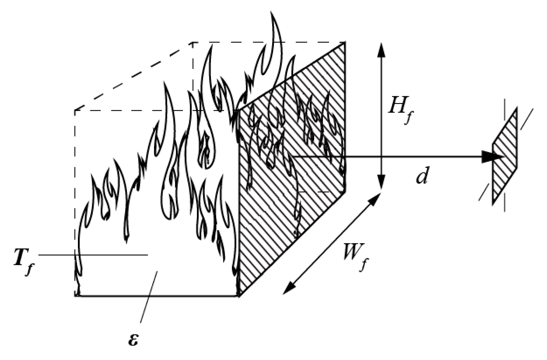
Figure 1. Schematic representation of the radiation model.
Fire 05 00093 g001
Figure 2. Dynamic fuel model process from Scott and Burgan [47].
Fire 05 00093 g002
Figure 3. Daily and weekly average wind speed in Montreal 2019.
Fire 05 00093 g003
Figure 4. Configuration of fire front and the target, as presented in AS3959 [40].
Fire 05 00093 g004
Figure 5. Radiation heat flux as a function of distance to the façade (d) for different fuel categories: (a) for Grasses, (b) for Grass-Shrubs, (c) for Shrubs.
Fire 05 00093 g005
Figure 6. Safe separation distances as a function of wind speed at very low MC (D1L1) for each fuel model: (a) Grasses, (b) Grass-Shrubs, (c) Shrubs.
Fire 05 00093 g006aFire 05 00093 g006b
Figure 7. Safe separation distances as a function of wind speed at Low MC (D2L2) for GR fuel models.
Fire 05 00093 g007
Figure 8. Safe separation distances as a function of wind speed at low MC of live fuel (L2) and variable MC of dead fuel (D2, D3, D4) for each fuel model of GR category: (a) GR-2, (b) GR-3, (c) GR-4.
Fire 05 00093 g008
Figure 9. Safe separation distances as a function of wind speed at Low MC (D2L2) for GS fuel models.
Fire 05 00093 g009
Figure 10. Safe separation distances as a function of wind speed at Low MC of live fuel (L2) and variable MC of dead fuel (D2, D3, D4) for each fuel model of GS category: (a) GS-1, (b) GS-2, (c) GS-3.
Fire 05 00093 g010
Figure 11. Safe separation distances as a function of wind speed at Low MC (D2L2) for SH fuel models.
Fire 05 00093 g011
Figure 12. Safe separation distances as a function of wind speed at Low MC of live fuel (L2) and variable MC of dead fuel (D2, D3, D4) for each fuel model of SH category: (a) SH-2, (b) SH-4, (c) SH-8.
Fire 05 00093 g012
Figure 13. Safe separation distances as a function of wind speed at Moderate MC of live fuel (L3) and variable MC of dead fuel (D2, D3, D4) for each fuel model of GR category: (a) GR-2, (b) GR-3, (c) GR-4.
Fire 05 00093 g013
Figure 14. Safe separation distances as a function of wind speed at Moderate MC (D3L3) for GS fuel models.
Fire 05 00093 g014
Figure 15. Safe separation distances as a function of wind speed at Moderate MC of live fuel (L3) and variable MC of dead fuel (D2, D3, D4) for each fuel model of SH category: (a) SH-2, (b) SH-4, (c) SH-8.
Fire 05 00093 g015
Figure 16. Safe separation distances as a function of wind speed at High MC (D4L4) for SH fuel models: (a) SH-2, (b) SH-4, (c) SH-8.
Fire 05 00093 g016
Table 1. Fuel models [47].
Fuel ModelFine Dead Fuel Load
(kg/m2)
Live Herbaceous Load
(kg/m2)
Live Woody Load
(kg/m2)
Mean Fuel Height
(m)
Grass
GR-20.020.25-0.3
GR-30.020.37-0.6
GR-40.060.47-0.6
Grass-Shrub
GS-10.050.120.160.3
GS-20.120.150.250.5
GS-30.070.360.31<0.6
Shrub
SH-20.33-0.950.3
SH-40.21-0.630.9
SH-80.51-1.070.9
Table 2. Moisture scenarios according to Scott and Burgan [47].
FuelMC, %
Very LowLowModerateHigh
DeadD1D2D3D4
1-h36912
10-h471013
100-h581114
LiveL1L2L3L4
Herbaceous306090120
Woody6090120150
Table 3. Moisture scenarios used.
Dead Fuel Moisture
D1D2D3D4
Live fuel moistureL1GR, GS, SH
L2 GR, GS, SHGR, GS, SHGR, GS, SH
L3 GR, GS, SHGR, GS, SHGR, GS, SH
L4 SHSHSH
Publisher’s Note: MDPI stays neutral with regard to jurisdictional claims in published maps and institutional affiliations.