Abstract
It is common for fire engineers in the UK to consider a time-dependent series of events when using the Fire Dynamics Simulator to assess the performance of residential corridor smoke control systems. A significant proportion of this established timeline focusses on producing the necessary buildup of smoke and heat in the apartment of origin, prior to any smoke spreading to the corridor or stairs. This paper proposes an alternative approach that enables a compressed modelling timeline by using uniform initial condition parameters in the apartment of origin for the soot mass fraction, room gas temperature, wall and ceiling temperatures, and slab temperature. These conditions can be applied from the outset for separate means of escape and firefighting phases, providing greater flexibility and reducing the wall-clock times for simulations. To achieve this, simulations for a 1000 kW medium growth rate fire in a single reasonable worst-case exemplar arrangement were undertaken using an established timeline approach. This was then used to estimate the approximate initial conditions needed to inform the compressed timeline input parameters. When comparing the established and compressed timeline approaches, close agreement was demonstrated for the estimated conditions of corridor visibility and temperature. The paper also suggests prospective correlations for the initial condition parameters needed to represent a given maximum heat release rate. The paper ultimately provides engineers with a method for residential corridor smoke control modelling that reduces simulation times, as well as providing greater consistency in the demonstrated performance, by proposing initial conditions independent of the dimensions of the apartment.
1. Introduction
A number of UK fire safety guidance documents [1,2,3] recommend that the residential corridors of multi-apartment buildings be afforded a means of smoke control. In instances where the travel distances within the corridor are greater than the maximum bounds recommended in these guidance documents, a mechanical (or combined mechanical and natural) smoke control system is often adopted. The purpose of this system is to return the extended corridor and associated stair enclosure to tenable conditions, as well as to protect the stair from smoke ingress during fire service operations [4]. Further discussion on the role of residential smoke control in UK design can be found elsewhere [4,5]. To determine whether the proposed smoke control system can adequately support a design incorporating extended corridors, a performance-based fire and smoke modelling assessment is usually undertaken [6], with the computational fluid dynamics (CFD) based Fire Dynamics Simulator (FDS) [7,8,9] software being the de facto tool applied by most engineers within the UK consultancy environment [10]. By default, FDS adopts a very large eddy simulation (VLES) turbulence model, solving an incompressible form of the Navier–Stokes equations on a structured cartesian grid (or ‘mesh’).
The most regularly adopted UK document on the assessment of residential corridor smoke control systems is the Smoke Control Association (SCA) guidance on smoke control to common escape routes in apartment buildings (flats and maisonettes) [11], although fire engineers are free to adopt alternative guidance or utilise tailored performance-based methods [6]. Currently, it is common for engineers to consider a time-dependent series of events. SCA guidance also provides high-level illustration of steady state analyses, although these are generally only considered applicable in limited situations, with the SCA guidance suggesting “this approach allows a straightforward comparison of different geometries and ventilation methods. It does not, however, capture the transient nature of an actual fire scenario, where the fire develops with time and doors open and close at various stages during the event” [11]. In addition, the default VLES turbulence model used in the industry-standard FDS modelling tool is inherently transient, and thus limited in how it can address true steady state problems [12]. Therefore, a time-dependent approach to the assessment of residential corridor smoke control in FDS typically considers the following phases:
- A fire ignites within an apartment, and begins to grow following a characteristic αt2 [13] growth rate.
- Once the fire reaches a certain heat release rate (HRR), it is assumed that occupants then escape from the apartment. The door from the fire-affected apartment (which connects to the residential corridor) opens.
- Smoke enters the corridor while the apartment door is open and the door then closes. Consideration may also be given to the opening and closing of stair doors during escape.
- The corridor smoke control system activates and clears the corridor of smoke, with the performance of the system determined with respect to the duration of time it takes to return the corridor to tenable conditions.
- Once the corridor is returned to tenable conditions, firefighting operations are considered. To represent the arrival and actions of firefighters, doors to the stair and apartment are opened for a prolonged period, and substantial quantities of hot smoke enter the corridor. The purpose of this period is to assess the corridor and stair conditions for firefighting tenability.
For this timeline, it is common for practitioners to represent a fire growing for a period of up to 300 s (5 min), with SCA guidance suggesting “if a medium growing t-squared fire is assumed, then after 5 min the heat release rate will be approximately 1 MW. This size of fire might be considered as appropriate at the time the occupants of the fire apartment make their escape” [11]. Following the recommendations of SCA guidance, the apartment door is opened for a 20 s period and, after this, it is generally expected that the corridor will return to tenable conditions within 120 s (2 min), resulting in a total simulation time for means of escape of 440 s (7 min 20 s). A significant proportion (~68%) of the means of escape phase is therefore concerned with conditions within the apartment, with only 32% of the phase focusing on the conditions within the common corridor. In addition, the simulation may be run for approximately 8 min (sometimes longer) before firefighting operations are considered. Thus, it is possible that the simulation could identify adequate smoke control performance during the means of escape phase, and then, much later in the simulation timeline, indicate a failure of the system to adequately support firefighting operations.
The discussion highlights how the established residential corridor smoke modelling timeline includes a large proportion of ‘wasted’ simulation time, when the primary intent in this period is to fill the apartment with hot smoke. Another limitation is the lack of flexibility in considering separately the means of escape and firefighting phases. If the two phases are separated, it allows for more freedom in assessing independently the two system performance objectives.
In consideration of the above, this paper details an exercise where the established time-dependent approach was used to estimate initial apartment conditions for a compressed modelling timeline. In considering this alternative method, initial regions were adopted to define gas phase temperature and soot concentration within the apartment from the outset of the simulation, as well as boundary temperatures, eliminating the need to simulate the fire growth period. This approach divides the means of escape and firefighting phases, providing a greater degree of flexibility in being able to assess each phase separately.
2. Established Timeline Methodology
2.1. Overview
To determine the inputs needed to represent the initial conditions in the compressed timelines, a CFD-based fire and smoke modelling analysis was undertaken in FDS version 6.7.7 [7], software developed by the National Institute of Standards and Technology (NIST) in Gaithersburg, Maryland (https://pages.nist.gov/fds-smv/downloads.html, accessed on 10 January 2022).
To represent what are intended to be standard industry practices, the established timeline modelling applied the deterministic assumptions provided in SCA guidance, including SCA guidance on smoke control, to common escape routes in apartment buildings (flats and maisonettes) [11], and SCA guidance for CFD analysis for smoke control design inside buildings [14]. Where neither of these documents provided a specific recommendation, previous revisions of SCA guidance were considered [15,16,17]. In cases where recommendations are provided in neither the existing nor previous SCA guidance, parameters were adopted from the work of Hopkin et al. [4] on deterministic assumptions of residential corridor smoke control design, or from elsewhere in the published literature.
The modelling assessed the conditions for a single exemplar residential corridor arrangement, based on the recommendations of fire safety guidance and relevant housing survey data. The approach taken for the compressed timeline modelling, and the means of estimating the necessary inputs for the initial conditions, are discussed in the subsequent sections.
2.2. Exemplar Geometry
The CFD-based fire and smoke modelling of residential common corridor smoke control systems is most frequently undertaken during the design process, prior to building construction and occupation, with a focus on evaluating ‘reasonable worst-case’ fire scenarios. Hence, a simple exemplar (i.e., a hypothetical building situation) is addressed herein, rather than addressing and benchmarking the methodology against historical smoke control arrangements and associated experiments. With respect to this approach, it has been suggested previously that there is a “limited amount of historical and quantitative data available where the performance of residential corridor smoke control systems within buildings under real fire conditions has been demonstrated” [5].
Figure 1 presents the exemplar geometry adopted for the modelling exercise. The arrangement consists of an apartment (i.e., the enclosure of fire origin), a corridor, and a stairway. The purpose of the exemplar is to capture conditions within the apartment enclosure and to represent the impact this may have on a residential corridor, with no consideration given to whether an adequate design performance is demonstrated.
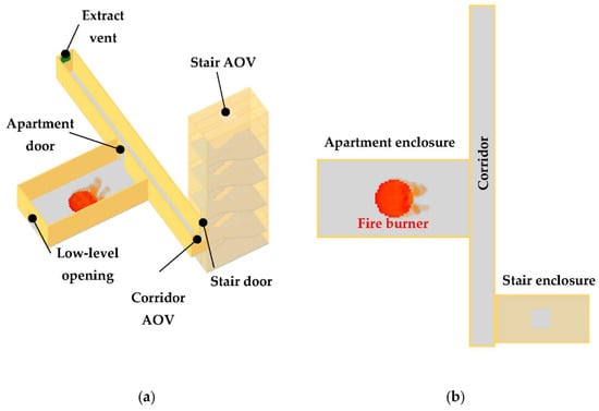
Figure 1.
Exemplar geometry visualisation presented in the Smokeview software package [18]: (a) 3D perspective view; and (b) plan view.
The corridor was 18 m long by 1.2 m wide by 2.4 m tall. The 18 m length was selected to represent a corridor with an extended single direction travel distance, which is greater than the recommended upper bound provided in BS 9991:2015 [2] of 15 m travel distance in a residential corridor where sprinkler protection is provided. The corridor was ventilated with a mechanical exhaust vent at one end (0.8 m by 0.8 m), achieving a fixed volumetric flow rate of 4 m3/s. Inlet was provided at the opposite end of the corridor by an automatically openable vent (AOV) to external air, with a geometric free area of 0.96 m2 (0.8 m wide by 1.2 m high). The adopted exemplar and ventilation provisions were consistent with previous studies by Hopkin et al. [4].
The stair enclosure was simulated with dimensions of 5 m long by 2.4 m wide by 15 m tall, representative of a five-storey tall building (ground plus four) with a height from access level to the uppermost storey of 12 m. A single 1 m by 1 m (geometric free area) AOV was located at the head of the stair, in line with the guidance of BS 9991:2015 [2]. Doors connecting the apartment to the corridor and the corridor to the stair were simulated as 0.8 m wide by 2 m high, considered broadly representative of a standard residential door size [19].
An 8 m by 4 m (32 m2) open-plan apartment enclosure was used for the room of fire origin, with a representative floor-to-ceiling height of 2.4 m. A low-level opening 1.2 m wide by 1.3 m tall was incorporated into the apartment enclosure. The dimensions aligned with the 1.25 m by 1.25 m opening area recommended in SCA guidance [11] for illustrative steady state conditions, with minor adjustments to fit the selected mesh arrangement. The purpose of the opening was to allow enough oxygen to reach the fuel bed to sustain the design fire’s HRR (discussed in a later section). This low-level opening may also be considered broadly representative of potential window openings or leakages present within the apartment.
The apartment enclosure dimensions aligned with the smallest open plan apartment assessed in the NF 19 ‘open plan flats’ study [20], and also with the maximum area in the BS 9991:2015 [2] guidance for an apartment incorporating an unenclosed kitchen. When analysing English Housing Survey (EHS) data, Hopkin et al. [21] identified that an average one-bedroom apartment has a floor area of 44.9 m2 (from 7099 samples), compared to an average of 81.9 m2 (from 1309 samples) for three-bedroom apartments. Data from Scott Wilson [22] suggests a mean floor area of 32.1 m2 (from four samples) for studio apartments. An 8 m by 4 m apartment is therefore considered small in the context of observed UK apartment sizes.
Adopting a smaller apartment for a given design fire provides estimations of a denser accumulation of gas phase soot and heat within the enclosure when compared to larger apartments. The result of this is a greater initial quantity of smoke and heat entering the corridor whenever the apartment door opens, during means of escape or firefighting. Thus, any recommendations derived from this exercise will be inherently conservative should they then be applied to larger apartments. The recommendations will also assist in providing a more consistent level of demonstrated safety across different fire scenarios, such that the observed performance of a corridor smoke control system will be largely independent of the simulated apartment size.
2.3. Mesh Configuration and Computing Process
The modelling was undertaken with a uniform cell size of 0.1 m throughout, resulting in a total of 378,560 cells in the domain. The domain was separated into nine separate meshes and assigned to eight message passing interface (MPI) processes, each accommodating on average 47,000 cells. To explore the impact of the compressed timelines on the computational run times, consideration was also given to a domain that was assigned into four MPI processes (approximately 95,000 cells per MPI process). Each of these MPI processes was assigned to a single physical core (either eight or four cores in total) of an AMD EPYC 7282 processor, with a single OpenMP thread per MPI process (i.e., N_THREADS = 1). Discussion on cell size selection and mesh sensitivity, as well as computational benefits, is provided in Section 4.1 and Section 5.3, respectively.
2.4. Design Fire Properties
Table 1 presents the design fire properties adopted for the established timeline modelling. The modelling considers a 1000 kW maximum HRR with a medium growth rate, after the SCA guidance’s suggestion that “this size of fire might be considered as appropriate at the time the occupants of the fire apartment make their escape” [11]. This maximum HRR was also applied for the firefighting phase, which anecdotally aligns with a commonly considered ‘sprinkler-capped’ HRR. For reference, a 1000 kW maximum HRR aligns with the 75th percentile estimated from fire incident data for apartments without sprinkler protection, with a medium growth rate approximately aligning with the 95th percentile value [23].

Table 1.
Summary of the design fire properties used in the established timeline modelling.
To represent the fire, a radial fire spread model was adopted to capture the increase in fire area as the fire grew. This was achieved by defining a burner radius and applying a radial fire spread rate. The fire therefore grew at a spread rate of = 0.00342 m/s until the maximum HRR of 1000 kW was met. The selected spread rate was equivalent to a medium growth rate of α = 0.0117 kW/s2. The relationship can be summarised as [24]:
where is the HRR (kW), α is the fire growth rate (kW/s2), is time (s), is the heat release rate per unit area (HRRPUA) (kW/m2), r is the radius of the fire (m), and is the spread rate (m/s).
2.5. Surface Properties
Table 2 provides the surface properties adopted for the modelling geometry. All walls and ceiling obstructions were modelled as 15 mm gypsum plasterboard surfaces based on properties defined by Hopkin et al. [26], and floor slabs were simulated with concrete properties estimated from BS EN 1992-1-2:2004+A1:2019 [27].

Table 2.
Surface properties.
It is acknowledged that the properties given in Table 2 represent a considerable simplification of the wider range of building materials which could be used in practice. However, the intention of adopting these properties was not to provide a detailed representation of potential building materials, but instead to produce a more representative estimation of temperature losses at the boundaries than if fixed temperature Dirichlet boundary conditions were adopted (i.e., using the default ‘INERT’ boundary in FDS).
2.6. Established Timeline
Table 3 presents a summary of the established modelling timeline. This broadly aligns with SCA guidance, acknowledging that there will be a certain degree of variation in circumstances where the guidance is not explicit, or where the input assumptions are dependent on the specific arrangement or ventilation provisions being assessed.

Table 3.
Established timeline incorporating the means of escape and firefighting phases.
The activation of the smoke control system was linked to smoke detection (D) within the corridor. For this, smoke detector properties were adopted for a photoelectric P01 model with an αC of 1.0, αe of 1.8, βc −0.8 and βe −1.0 [7]. An obscuration threshold of 30 %/m was applied, representing 91st and 86th percentiles for the smoke detection of flaming fires when considering studies on ionisation and photoelectric detectors, respectively [28].
3. Compressed Timeline Methodology
3.1. Quantifying and Defining Relevant Inputs
To estimate initial conditions within the apartment enclosure necessary to simulate the compressed timelines, a number of statistical regions were incorporated into the modelling of the established timeline (detailed in the previous sections). These included:
- The spatially-averaged soot mass fraction for the entire apartment enclosure volume.
- The spatially-averaged apartment gas temperature for the entire apartment enclosure volume.
- The spatially-averaged ‘wall temperature’ of each surface in the apartment (i.e., the four walls, ceiling, and slab surfaces). These were subsequently separated into two inputs: (1) walls and ceilings, assumed to be plasterboard; and (2) the floor slabs, assumed to be concrete. The temperature for the walls and ceilings were spatially averaged as a proportion of their respective areas to represent the combined total surface area.
Plots for the above parameters, observed in the established timeline modelling, are presented in Figure 2. Shown in the plots are a red square which indicates the input parameter for the compressed timelines, taken at 460 s within the established timelines (i.e., the time of fire service arrival to the apartment). For later simplification of modelling inputs, this value was rounded up to the nearest 10 °C for the room, wall, and slab temperatures, and hence does not perfectly align with the data presented in the plots.
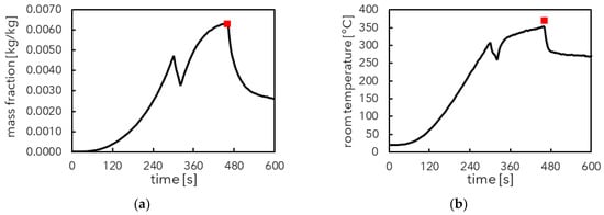
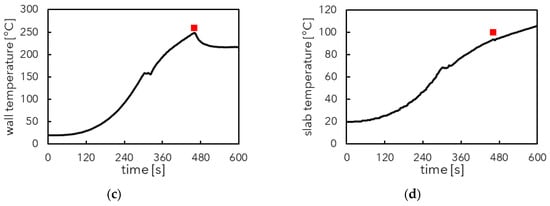
Figure 2.
Results for established timeline, spatially-averaged for the full apartment volume: (a) soot mass fraction; (b) room gas temperature; (c) wall/ceiling temperature; and (d) slab temperature. Red marker rounded to nearest 10 °C for (b–d).
In taking the approach of applying spatially-averaged values, it was assumed that the apartment enclosure conditions can be uniformly represented. In practice, conditions will vary throughout the domain. This is demonstrated in Table 4, with the minimum, maximum, mean, and standard deviation values presented for the soot mass fraction, apartment gas temperature, wall/ceiling temperature and slab temperature across the entire apartment enclosure (for a series of devices spaced at 0.5 m intervals). However, attempting to represent this variation as an initial condition would be a complex and time-consuming endeavour. To verify that the assumption of applying spatially-averaged values is reasonable, comparisons were made between the simulation outputs for the established timeline and the compressed timeline for key performance criteria typically observed in residential corridor assessments. This comparison was undertaken to demonstrate whether the assumed uniformity of the initial conditions within the apartment enclosure had an appreciable impact on conditions estimated within the corridor.

Table 4.
Descriptive statistics for the established timelines, recorded by devices for the entire initial region or boundary condition.
For the purposes of simplifying the method, the same initial condition input parameters were used both for the means of escape and firefighting phases (t = 460 s, the time that the apartment door opens for firefighting). This is considered a conservative approach, as it estimated ‘poorer’ apartment conditions for the means of escape phase when compared with those observed in the established timeline, such that a greater quantity of soot and higher temperatures were applied.
3.2. Modelling Assumptions and Compressed Timelines
Using the values estimated from the established timeline results (Figure 2), the initial conditions detailed in Table 5 were adopted for the compressed timelines. All other parameters were consistent with those detailed for the established timeline, with the exception of the HRR being simulated at its maximum 1000 kW steady state, with a nominal 1 s ramp-up period.

Table 5.
Parameters adopted for the compressed timelines, applied for the entire initial region or boundary condition.
Table 6 and Table 7 present the compressed timelines adopted for the means of escape and firefighting phases, respectively. From visual inspection of the simulation results, a 5 s initial period was shown to be sufficient before opening the apartment door. This approach did not capture the pre-door opening flow field that was generated in the established timeline, but this was not shown to have an appreciable influence on the outcome, due to the short time required for the flow field to be established. Depending on the complexity of the arrangements and scenarios being assessed, practitioners may wish to extend this initial delay.

Table 6.
Compressed means of escape timeline.

Table 7.
Compressed firefighting timeline.
3.3. Defining the Initial Region Parameters in FDS
To assist the reader in applying the methods detailed in this paper, Figure 3 presents an example of the FDS coded input for the initial region definition of the soot species mass fraction and room gas phase temperature. Figure 4 presents the material and surface definitions for the walls, ceilings, and slabs, conservatively equating the wall surface temperature assessed in the established timeline with an inner wall temperature in the compressed timeline. These surface properties were only applied to the internal apartment walls, ceiling, and slab. All other surfaces applied a separate surface definition with a default ambient inner temperature. That is, the surfaces of other rooms and enclosures were specified separately as plasterboard or concrete (where appropriate), without any definition for TMP_INNER.

Figure 3.
Example FDS input for specification of the initial region in the apartment enclosure.
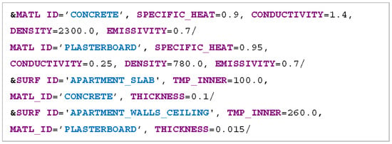
Figure 4.
Example FDS input for definition of inner temperatures of apartment walls, ceilings, and slabs.
By defining only the mass fraction of soot in the initial region, it is assumed that the remaining proportion of the volume comprises ‘AIR’. Consideration was not given to other products of combustion, like carbon monoxide (CO) and carbon dioxide (CO2) [29], on the assumption that criteria such as the fractional effective dose (FED) [30] are not typically assessed in common corridor analyses. As the assessment is typically dominated by temperature-related buoyancy, any differences in interspecies densities were not anticipated to have an appreciable impact on the simulation outcomes. It was also assumed that the enclosure of fire origin was sufficiently well-ventilated to have limited FUEL present outside the combustion zone.
3.4. The Application of a Compressed Timeline CFD-Based Modelling Approach
In taking the approach of representing apartment conditions using uniform initial regions with spatially-averaged values, the apartment enclosure begins the simulation akin to a quasi-single fire zone. Therefore, it could be postulated that the application of computationally intensive CFD-based fire and smoke modelling is unwarranted, and instead a zone model would be sufficient to address the design problem to an adequate fidelity. Hopkin et al. [4] observed the value of adopting a zone modelling approach for simulating residential common corridor smoke control systems, with particular acknowledgement of the benefit of undertaking probabilistic assessments to create an understanding of a range of potential outcomes. Hopkin et al. also made reference to the ‘consistent level of crudeness’ concept [31,32], where it is proposed that the level of detail in a process should be governed by its crudest part.
Johansson [33] noted that the adoption of a two-zone model is useful in situations where “the hot gas layer can be assumed to be uniform in regard to temperature and composition”, with reference to smaller enclosures in residential buildings, but then goes on to advise that two-zone models are more limited once enclosures become larger, such as in commercial and industrial buildings.
Despite these observations, there are situations where two-zone models may become limited in their application even for smaller enclosures. These include complex residential arrangements and smoke control solutions, e.g., in corridors incorporating changes in direction and/or integrating various mechanical or natural ventilation components. In such situations, the specific location of these components within the enclosure, and the resultant velocities which are generated, could have an appreciable impact on the demonstrated performance of the system, which is not necessarily captured within a zone model. As a result, there is a common expectation within the UK fire safety industry that a CFD-based modelling assessment should be undertaken (Section 1).
The proposed compressed timeline approach is therefore able to provide value to practitioners in circumstances where they wish to evaluate complex smoke and air-flow phenomena in a domain which sits outside a relatively simple enclosure of fire origin.
4. Sensitivity Studies
4.1. Mesh Sensitivity
For the selection of the mesh cell size, the SCA guidance suggests “for smaller enclosures, such as corridors and lobbies, a typical mesh size of 0.1 m in the near field and 0.2 m far field to the fire source are considered suitable” [14]. However, the document provides no further information on how these mesh sizes were determined as adequate.
The FDS validation guide [34] includes a series of benchmarking exercises (‘test series’) with parameters for numerical resolution, which are partly intended to outline the range of applicability of the validation studies [35]. These parameters include the characteristic fire diameter (), using the maximum HRR, and the plume resolution index (). The latter, in particular, is dependent on the selected cell size (). Relevant test series and the associated numerical parameters are summarised in Table 8. Previously, the research document NUREG-1824 [36] included a series of sensitivity analyses carried out for FDS where suitable values typically ranged from 4 to 16. McDermott et al. [37] have also indicated that “ ≈ 10 has historically been considered adequate grid resolution”.

Table 8.
Relevant FDS validation guide [34] test series.
A maximum fire size of 1000 kW modelled with a 0.1 m cell size achieves a value of ~9.6, which sits within the NUREG-1824 recommended range, being within (or greater than) the range of values shown in relevant test series of the validation guide.
The arrangement and smoke control solution presented in this paper is consistent with the exemplar adopted by Hopkin et al. [10] in their study on the significance of mesh resolution against scenario uncertainty in the modelling of residential smoke control systems. In the study, three different mesh quality metrics were assessed for the non-dimensional wall distance, the wavelet error measure, and the measure of turbulence resolution. These measures were then considered in the context of scenario uncertainty, generated by a probabilistic risk assessment using a series of FDS simulations. Hopkin et al. ultimately concluded that for a cell size of 0.1 m or less, the uncertainty associated with the model inputs had a more significant impact on the confidence of a given design solution than the variation arising from the selected mesh cell size. Furthermore, nominal deviations were observed between 0.05 m and 0.1 m cell sizes for the estimated corridor smoke clearance time. On this basis, and considering the relevant test series of the FDS validation guide, it appears reasonable to apply a uniform 0.1 m cell size for the modelling.
As a means to further verify that the estimated uniform conditions within the apartment enclosure are not dependent upon the adopted grid size, a mesh sensitivity analysis was undertaken in line with the recommendations of the FDS user’s guide [7]. This recommends that “in general, you should build an FDS input file using a relatively coarse mesh, and then gradually refine the mesh until you do not see appreciable differences in your results”. While this method does not guarantee convergence as the mesh is refined, due to the turbulence model adopted (VLES), it is nevertheless a practical method adopted by engineers to satisfy themselves that the conclusions drawn from their analysis are not sensitive to mesh density.
For this purpose, the established timeline was simulated for three different uniform cell sizes of 0.2 m, 0.1 m, and 0.05 m. Given that the primary aim of the modelling methodology is to estimate representative conditions within the apartment enclosure, the sensitivity analysis focussed on this part of the modelling domain and excluded the corridor and stairs. While the conditions within the corridor and stairway form a key consideration for mesh sensitivity, these were judged to be adequately addressed in the previous studies discussed above.
Figure 5 presents the spatially-averaged soot mass fraction and spatially-averaged room gas temperature at a time of 460 s (7 min 40 s). From this it can be observed that the results were largely similar across the three cell sizes, with the coarsest mesh (0.2 m) estimating a larger spatially-averaged soot mass fraction and room gas temperature. No appreciable differences were observed between the 0.1 m and 0.05 m cell sizes. Thus, the 0.1 m mesh adopted in this paper is considered adequate. Minor variations were observed in the values presented here and those presented in the previous comparison of results, due to small adjustments made to the geometry to align with the coarser 0.2 m cell size.
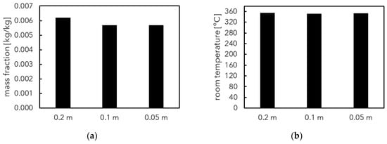
Figure 5.
Comparison of results for mesh sensitivity study, measured in the full apartment volume at t = 460 s: (a) mean soot mass fraction; and (b) mean temperature.
4.2. Enclosure Area Sensitivity
The main analyses considered an enclosure which is 8 m long by 4 m wide. This is considered to be a reasonable worst-case, on the basis of typical apartment dimensions captured in fire safety guidance, and data from historical housing surveys. A smaller fire enclosure is deemed to be worse due to the potential for greater accumulation of gas phase soot and heat. To demonstrate this point, a sensitivity analysis was carried out that considered six different apartment enclosure areas: (1) 4 m by 4 m; (2) 8 m by 4 m; (3) 8 m by 8 m; (4) 12 m by 8 m; (5) 12 m by 12 m; and (6) 16 m by 12 m. All other input assumptions were consistent with those adopted for the established timeline.
Figure 6 presents the spatially-averaged soot mass fraction and room gas temperature (at a time of 460 s) as a function of the enclosure volume. As would be expected, both of these parameters were observed to decrease in value as the enclosure area increased in size. An interesting observation is that the soot mass fraction for the 8 m by 4 m enclosure and 4 m by 4 m enclosure are reasonably consistent, indicating that a reduction in area below 8 m by 4 m did not result in a noticeable increase in the quantity of spatially-averaged soot estimated in the enclosure.
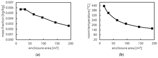
Figure 6.
Comparison of results for enclosure area sensitivity study, measured in the full apartment volume at t = 460 s: (a) mean soot mass fraction; and (b) mean temperature.
5. Results Comparison
5.1. Means of Escape
Figure 7 provides a comparison between the established and compressed timeline approaches for the means of escape phase. In particular, the figures present a comparison for the soot mass fraction, soot volume fraction, visibility, and temperature, measured as spatially-averaged values across the full corridor volume. Each plot is presented from the time that the apartment door opens for escape.
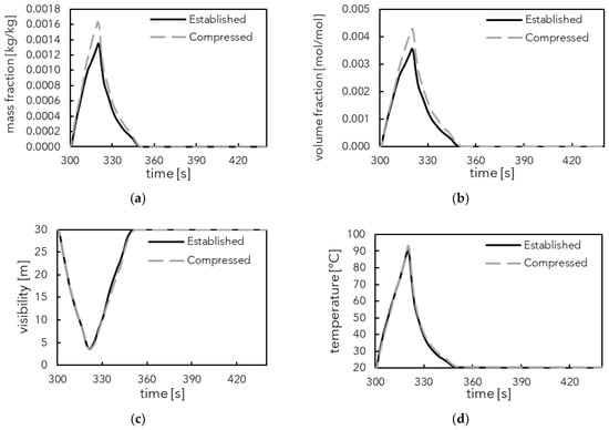
Figure 7.
Results for means of escape phase, spatially-averaged for the full corridor volume: (a) soot mass fraction; (b) soot volume fraction; (c) visibility; and (d) temperature.
By focusing on spatially-averaged values across the full corridor volume, the results present a broad understanding of the quantity of soot, visibility, and temperatures observed within the ventilated enclosure. However, the plots do not provide a detailed indication of the distribution of smoke within the corridor, in terms of its spread along the corridor length and the formation of an upper smoke layer and lower clear layer. Therefore, additional results are presented in Figure 8 for spatially-averaged visibility across the corridor length at heights of 1.5 m and 2 m from floor level, respectively, as well as the visibility observed in the corridor at the respective locations of the apartment door and the stair door at a height of 2 m from floor level. To provide a more detailed presentation of the distribution of smoke, Figure 9 includes the visibility contour plots across various time intervals, at a height of 2 m from floor level. This is representative of a conservative occupant head height and is a commonly adopted reference height for the means of escape phase; for example, PD 7974-0:2002 [38] suggests conditions are untenable once “the smoke layer height [descends] to within 2.0 m of floor level”. A vertical section through the centreline of the corridor is also presented.
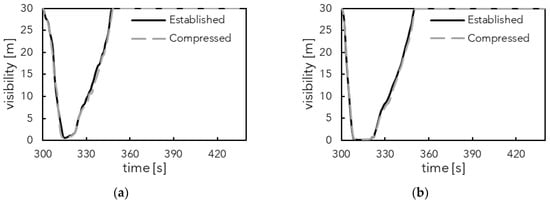
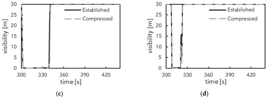
Figure 8.
Additional results for the means of escape phase: (a) spatially-averaged visibility 1.5 m from floor level; (b) spatially-averaged visibility 2 m from floor level; (c) visibility at the apartment door 2 m from floor level; and (d) visibility at the stair door 2 m from floor level.
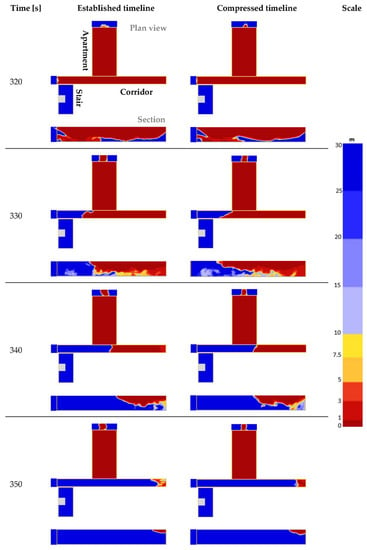
Figure 9.
Visibility contour plots for the means of escape phase at z = 2 m and through the corridor centreline.
The comparison demonstrates that the proposed initial region parameters resulted in a marginally greater spatially-averaged soot mass fraction and volume fraction within the full corridor volume. For the spatially-averaged corridor temperature and visibility, the results were shown to align almost identically. These observations were consistent with results presented in Figure 8. Visual inspection of the visibility contour plots for the two different approaches indicates a similar formation of the smoke layer and a comparable clearance of smoke within the corridor.
To measure the estimated differences between the established and compressed timeline values, the root mean squared error (RMSE) and normalised root mean squared error (NRMSE) were calculated [39]:
where, in this instance, is the number of time steps (taken every 1 s), is the value estimated in the compressed timeline for each output, is the value in the established timeline, and and are the minimum and maximum values in the established timeline. For these error measures, a value closer to zero indicates better agreement between the two approaches. Table 9 presents the RMSE and NRMSE for each of the outputs in Figure 7 and Figure 8, with the NRMSE ranging from 0.01 to 0.06.

Table 9.
RMSE and NRMSE between the established and compressed timeline outputs for the means of escape phase.
5.2. Firefighting
Figure 10 presents a comparison between the established and compressed timelines, for the same four spatially-averaged corridor volume parameters specified for the means of escape results. Each plot begins from the time that the apartment door opens for firefighting operations. Figure 11 includes the spatially-averaged temperature across the corridor length at heights of 1.5 m and 2 m from floor level, as well as the temperature observed in the corridor at the locations of the apartment door and the stair door, respectively, at a height of 1.5 m from floor level. For the temperatures shown at the apartment and stair doors, a 5 s moving average was adopted to reduce large fluctuations observed in the data.
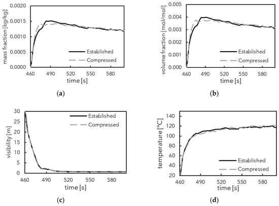
Figure 10.
Results for the firefighting phase, spatially-averaged for the full corridor volume: (a) soot mass fraction; (b) soot volume fraction; (c) visibility; and (d) temperature.
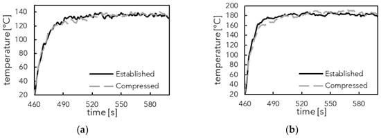
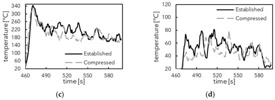
Figure 11.
Additional results for the firefighting phase: (a) spatially-averaged temperature 1.5 m from floor level; (b) spatially-averaged temperature 2 m from floor level; (c) temperature at the apartment door 1.5 m from floor level (5 s moving average); (d) temperature at the stair door 1.5 m from floor level (5 s moving average).
Figure 12 presents the temperature contour plots at a height of 1.5 m from floor level, which is the recommended reference height for firefighter tenability provided in SCA guidance and the fire brigade intervention model [40]. A vertical section through the centreline of the corridor is also shown. Table 10 presents the RMSE and NRMSE for each output, with the NRMSE values ranging from 0.01 to 0.04 for six of the assessed outputs. However, the temperatures at the apartment door and stair door produced greater NRMSE values of 0.11 and 0.25, respectively, although this was strongly affected by the range of the fluctuations in the data when assessing a single measurement point rather than a spatial-average.
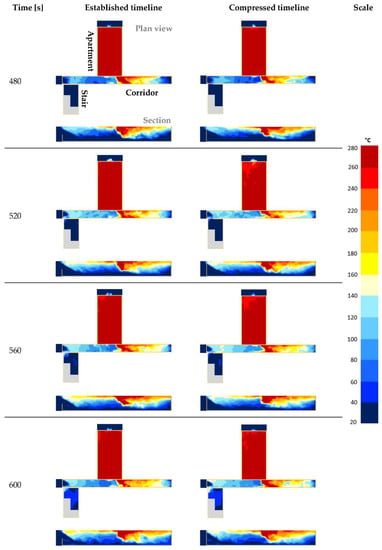
Figure 12.
Temperature contour plots for the firefighting phase at z = 1.5 m and through the corridor centreline.

Table 10.
RMSE and NRMSE between the established and compressed timeline outputs for the firefighting phase.
As with the means of escape phase, the comparison demonstrates a reasonable agreement in the observed results between the two methods, including for the development of temperatures along the corridor length. On this basis, the proposed initial condition assumptions appear to adequately capture the estimated corridor conditions from the established timeline approach.
5.3. Computational Benefits
An expected benefit of adopting a compressed timeline is the reduction in the time taken to run the simulations (typically called the wall-clock time). To demonstrate this, Table 11 presents the wall-clock time for each of the simulation cases, using eight or four physical cores. Table 12 then presents a comparison of the total wall-clock times between the established and compressed cases.

Table 11.
Elapsed wall-clock times for each of the timeline approaches for eight and four physical cores.

Table 12.
Comparison of the total wall-clock time for the established and compressed timeline approaches. Notation aligns with Table 11.
In this instance, elapsed wall-clock times for the established case ranged from approximately 5 h 53 min for eight cores to 8 h 18 min for four cores. The compressed timeline wall-clock times ranged from around 1 h 41 min to 2 h 19 min, depending on the number of cores and the modelling phase. The compressed timeline is shown to provide a computational benefit resulting in a 42% to 45% reduction relative to the established timeline, subject to the number of cores used.
This is a single example for a reasonably simple geometry and smoke control solution, while larger and more complex arrangements would be expected to take longer to run. Examples may be impacted by a number of factors, including the hardware and computing capacity available, the mesh arrangements, cell numbers, the numbers of OpenMP threads or MPI processes used, simulation parameter assumptions for time steps and results output, etc. [41,42]. However, it provides an indication of the computational benefits of being able to adopt compressed timelines in place of an established transient approach. This is particularly valuable in instances where practitioners are required to run a large quantity of simulations either simultaneously or in a workload queue, with limited computing resources available relative to the demand.
5.4. Maximum HRR
Engineers may wish to undertake an assessment where the HRR differs from the commonly adopted 1000 kW value used in this paper. For example, they may wish to consider a larger HRR for an enclosure without sprinkler protection, or conversely, a smaller HRR may be desired should it be estimated that sprinkler activation occurs prior to HRR reaching 1000 kW. They may also wish to consider different HRR values for the means of escape and firefighting timelines. Therefore, a further sensitivity study was carried out, in which the established timeline was simulated for a series of maximum HRRs ranging from 250 kW up to 2500 kW. The input assumptions for the sensitivity study are consistent with those specified previously, with the exception of the maximum HRR, the associated burner radius or area, and the area of the low-level opening in the apartment enclosure.
To provide consistency in the area of the low-level opening across each HRR, the 1.25 m by 1.25 m vent area recommended in SCA guidance for a steady state 1000 kW HRR was approximated to a ratio between the HRR and the ventilation factor (A√H [43]), where A is the area of the opening (m2), and H is the height of the vent (m), assuming a square vent throughout. Sensitivity analyses (not reproduced herein, for brevity) indicate that the adopted low-level opening areas provide broad agreement with the estimated ventilation-controlled conditions, although further investigation of this assumption is warranted.
Figure 13 presents the spatially-averaged soot mass fraction, room gas temperature, wall and ceiling temperature, and slab temperature as a function of the maximum HRR at a simulation time of 460 s. Also presented in the figures are correlations to estimate the relationship between the HRR and each parameter. For the soot mass fraction, the values remained reasonably consistent irrespective of the maximum HRR, and thus a fixed value of 0.0063 kg/kg is proposed. This consistency is due to the increase in the low-level opening area required to sustain combustion, in contrast to the HRR; i.e., a greater quantity of soot is produced by the fire, but is then lost via the increased flow through the opening. The room, wall and ceiling, and slab temperatures are all estimated to follow a logarithmic relationship. Table 13 presents the proposed equations for each parameter (applicable for HRRs greater than 250 kW), along with example initial condition values for a 600 kW HRR (selected arbitrarily).
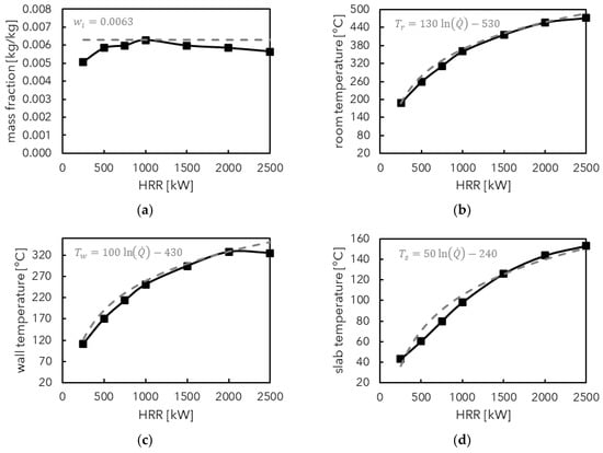
Figure 13.
Results comparison for the HRR sensitivity study, measured for the full apartment volume at t = 460 s: (a) mean soot mass fraction; (b) mean room temperature; (c) mean wall temperature; (d) mean slab temperature. Black lines indicate the simulation data and grey lines indicate the best-fit correlations.

Table 13.
Proposed equations for estimating initial region parameters as a function of the maximum HRR, with an example provided for a 600 kW fire.
6. Conclusions and Recommendations
This paper provides details of a compressed timeline approach to the FDS modelling of residential corridor smoke control systems, using initial conditions for the apartment gas phase soot mass fraction, room gas temperature, wall and ceiling inner temperature, and slab inner temperature. The benefits of this approach are that the engineer can reduce the time required to run the simulations compared to an established timeline (with the specific exemplar used in this paper indicating a 42–45% relative reduction) and consider independently the means of escape and firefighting phases for the modelling.
It is proposed that engineers can apply the compressed timelines given in Table 6 and Table 7, making any necessary adjustments to variables such as the smoke control activation time, stair door opening times, etc., to align with the fire scenario and building situation under consideration. Potential input parameters for the initial conditions for a typical 1000 kW maximum HRR are provided in Table 5, with a soot mass fraction of 0.0063 kg/kg uniformly distributed in the apartment enclosure, a room gas temperature of 370 °C, a wall/ceiling temperature of 260 °C, and a slab temperature of 100 °C. Alternatively, the prospective correlations presented in Table 13 suggest different initial conditions based on the maximum HRR. However, the application of these correlations is dependent on the adopted low-level opening and the assumed ratio between the HRR and the ventilation factor.
This paper forms part of ongoing work to enhance modelling approaches for the design of residential corridor smoke control systems. The proposed next steps include better quantification of acceptable failure likelihoods for these systems, for example, as a function of factors such as building height, number of apartments, or corridor length, and to identify suitable relationships between input parameter assumptions and target design confidence [44]. These relationships could then be used, along with the prospective correlations presented in Table 13, to propose appropriate initial conditions as a function of the risk to occupant health and safety for a given building situation.
Author Contributions
Conceptualization, C.H. and D.H.; Formal analysis, C.H. and J.H.L.; Investigation, C.H. and J.H.L.; Methodology, C.H., J.H.L., B.R. and D.H.; Visualization, C.H. and J.H.L.; Writing—original draft, C.H.; Writing—review & editing, J.H.L., B.R. and D.H. All authors have read and agreed to the published version of the manuscript.
Funding
This research received no external funding.
Institutional Review Board Statement
Not applicable.
Informed Consent Statement
Not applicable.
Data Availability Statement
Not applicable.
Conflicts of Interest
The authors declare no conflict of interest.
References
- HM Government. The Building Regulations 2010, Approved Document B (Fire Safety) Volume 1 (2019 Edition, as Amended May 2020); HM Government: London, UK, 2020.
- BSI. BS 9991: 2015 Fire safety in the design, management and use of residential buildings. In Code of Practice; BSI: London, UK, 2015. [Google Scholar]
- Scottish Government. Building Standards Technical Handbook 2019: Domestic; Scottish Government: Edinburgh, UK, 2019. [Google Scholar]
- Hopkin, C.; Spearpoint, M.; Hopkin, D.; Wang, Y. Using probabilistic zone model simulations to investigate the deterministic assumptions of UK residential corridor smoke control design. Fire Technol. 2022, 58, 1711–1736. [Google Scholar] [CrossRef]
- Hopkin, C.; Lay, S. Conceptual arguments on the use of unlatched reverse swing “flappy” door smoke control systems in residential buildings. Int. J. Build. Pathol. Adapt. 2022. ahead-of-print. [Google Scholar] [CrossRef]
- Hopkin, C.; Spearpoint, M.; Hopkin, D.; Wang, Y. Estimating door open time distributions for occupants escaping from apartments. Int. J. High-Rise Build. 2021, 10, 73–83. [Google Scholar] [CrossRef]
- McGrattan, K.; Hostikka, S.; McDermott, R.; Floyd, J.; Vanella, M. Fire Dynamics Simulator User’s Guide; National Institute of Standards and Technology: Gaithersburg, MD, USA, 2019. [CrossRef]
- McGrattan, K.; Hostikka, S.; McDermott, R.; Floyd, J.; Vanella, M. Fire Dynamics Simulator Technical Reference Guide Volume 1: Mathematical Model; National Institute of Standards and Technology: Gaithersburg, MD, USA, 2019. [Google Scholar]
- McGrattan, K.; Hostikka, S.; McDermott, R.; Floyd, J.; Vanella, M. Fire Dynamics Simulator Technical Reference Guide Volume 2: Verification; National Institute of Standards and Technology: Gaithersburg, MD, USA, 2019. [Google Scholar]
- Hopkin, D.; Hopkin, C.; Spearpoint, M.; Ralph, B.; van Coile, R. Scoping study on the significance of mesh resolution vs. scenario uncertainty in CFD modelling of residential smoke control systems. In Proceedings of the Interflam Conference, Royal Holloway, London, UK, 1–3 July 2019. [Google Scholar]
- Smoke Control Association (SCA). Guidance on Smoke Control to Common Escape Routes in Apartment Buildings (Flats and Maisonettes), Revision 3.1; Federation of Environmental Trade Associations: Wokingham, UK, 2020. [Google Scholar]
- Zhiyin, Y. Large-eddy simulation: Past, present and the future. Chin. J. Aeronaut. 2015, 28, 11–24. [Google Scholar] [CrossRef] [Green Version]
- PD 7974-1:2019; Application of Fire Safety Engineering Principles to the Design of Buildings. Initiation and Development of Fire within the Enclosure of Origin (Sub-System 1). BSI: London, UK, 2019.
- Smoke Control Association (SCA). Guidance on CFD Analysis for Smoke Control Design in Buildings, 1st ed.; Federation of Environmental Trade Associations: Wokingham, UK, 2021. [Google Scholar]
- Smoke Control Association (SCA). Guidance on Smoke Control to Common Escape Routes in Apartment Buildings (Flats and Maisonettes), Revision 1; Federation of Environmental Trade Associations: Wokingham, UK, 2012. [Google Scholar]
- Smoke Control Association (SCA). Guidance on Smoke Control to Common Escape Routes in Apartment Buildings (Flats and Maisonettes), Revision 2; Federation of Environmental Trade Associations: Wokingham, UK, 2015. [Google Scholar]
- Smoke Control Association (SCA). Guidance on Smoke Control to Common Escape Routes in Apartment Buildings (Flats and Maisonettes), Revision 3; Federation of Environmental Trade Associations: Wokingham, UK, 2020. [Google Scholar]
- Forney, G. Smokeview, a Tool for Visualizing fire Dynamics Simulation Data Volume I: User’s Guide; National Institute of Standards and Technology: Gaithersburg, MD, USA, 2020. Available online: https://pages.nist.gov/fds-smv/manuals.html (accessed on 15 March 2022).
- HM Government. The Building Regulations 2010, Approved Document M (Access to and Use of Buildings) Volume 1: Dwellings (2015 Edition Incorporating 2016 Amendments); HM Government: London, UK, 2016. [Google Scholar]
- Fraser-Mitchell, J.; Williams, C. Open Plan Flats: Assessing Life Safety in the Event of Fire; IHS BRE Press on behalf of the NHBC Foundation: Amersham, UK, 2009; Available online: https://www.nhbcfoundation.org/publication/open-plan-flats/ (accessed on 17 September 2019).
- Hopkin, C.; Spearpoint, M.; Hopkin, D.; Wang, Y. Residential occupant density distributions derived from English Housing Survey data. Fire Saf. J. 2019, 104, 147–158. [Google Scholar] [CrossRef] [Green Version]
- Scott Wilson. Housing Standards: Evidence and Research, Dwelling Size Survey; CABE: London, UK, 2010. [Google Scholar]
- Hopkin, C.; Spearpoint, M.; Wang, Y.; Hopkin, D. Design fire characteristics for probabilistic assessments of dwellings in England. Fire Technol. 2020, 56, 1179–1196. [Google Scholar] [CrossRef] [Green Version]
- Hopkin, D. Testing the single zone structural fire design hypothesis. In Proceedings of the Interflam 2013, 13th International Conference, Royal Hollway, London, UK, 24–26 June 2013; pp. 139–150. [Google Scholar]
- Hopkin, C.; Spearpoint, M.; Hopkin, D. A review of design values adopted for heat release rate per unit area. Fire Technol. 2019, 55, 1599–1618. [Google Scholar] [CrossRef] [Green Version]
- Hopkin, D.; Lennon, T.; El-Rimawi, J.; Silberschmidt, V. A numerical study of gypsum plasterboard behaviour under standard and natural fire conditions. Fire Mater. 2012, 36, 107–126. [Google Scholar] [CrossRef]
- BS EN 1992-1-2:2004+A1:2019; Eurocode 2. Design of Concrete Structures. General Rules. Structural Fire Design. BSI: London, UK, 2005.
- Geiman, J.; Gottuk, D. Alarm thresholds for smoke detector modeling. Fire Saf. Sci. 2003, 7, 197–208. [Google Scholar] [CrossRef] [Green Version]
- Hull, T.R.; Stec, A.A. (Eds.) Introduction to fire toxicity. In Fire Toxicity; Woodhead Publishing: Cambridge, UK, 2010; pp. 3–25. [Google Scholar] [CrossRef]
- Purser, D.; McAllister, J. Assessment of hazards to occupants from smoke, toxic gases, and heat. In SFPE Handbook of Fire Protection Engineering, 5th ed.; Springer: Berlin/Heidelberg, Germany, 2016; pp. 2308–2428. [Google Scholar]
- Elms, D. Consistent Crudeness in System Construction. In Optimization and Artificial Intelligence in Civil and Structural Engineering: Volume I: Optimization in Civil and Structural Engineering; Topping, B.H.V., Ed.; Springer: Dordrecht, The Netherlands, 1992; pp. 71–85. [Google Scholar] [CrossRef]
- Buchanan, A. The Challenges of Predicting Structural Performance in Fires. Fire Saf. Sci. 2008, 9, 79–90. [Google Scholar] [CrossRef] [Green Version]
- Johansson, N. Multi-Zone Models—Bridging the Gap between Two-Zone Models and CFD Models; SFPE Europe: Gaithersburg, MD, USA, 2020; Volume Q3, Available online: https://www.sfpe.org/publications/periodicals/sfpeeuropedigital/sfpeeurope19/europeissue19feature6 (accessed on 15 March 2022).
- McGrattan, K.; Hostikka, S.; McDermott, R.; Floyd, J.; Vanella, M. Fire Dynamics Simulator Technical Reference Guide Volume 3: Validation; National Institute of Standards and Technology: Gaithersburg, MD, USA, 2019.
- Hopkin, C.; Spearpoint, M.; Bittern, A. Using experimental sprinkler actuation times to assess the performance of Fire Dynamics Simulator. J. Fire Sci. 2018, 36, 342–361S. [Google Scholar] [CrossRef]
- McGrattan, K. Verification and Validation of Selected Fire Models for Nuclear Power Plant Applications, Volume 7: Fire Dynamics Simulator; U.S. Nuclear Regulatory Commission Office of Nuclear Regulatory Research: North Bethesda, MD, USA, 2007. Available online: https://www.nrc.gov/reading-rm/doc-collections/nuregs/staff/sr1824/v7/ (accessed on 16 September 2019).
- McDermott, R.J.; Forney, G.P.; McGrattan, K.B.; Mell, W.E. Fire Dynamics Simulator Version 6: Complex Geometry, Embedded Meshes, and Quality Assessment. In Proceedings of the Fifth European Conference on Computational Fluid Dynamics: ECCOMAS CFD 2010, Lisbon, Portugal, 14–17 June 2010; Available online: https://www.nist.gov/publications/fire-dynamics-simulator-version-6-complex-geometry-embedded-meshes-and-quality (accessed on 16 September 2021).
- PD 7974-0:2002; Application of Fire Safety Engineering Principles to the Design of Buildings. Guide to Design Framework and Fire Safety Engineering Procedures. BSI: London, UK, 2002.
- Botchkarev, A. A New Typology Design of Performance Metrics to Measure Errors in Machine Learning Regression Algorithms. Interdiscip. J. Inf. Knowl. Manag. 2019, 14, 45–76. [Google Scholar] [CrossRef] [Green Version]
- Buckley, G.; Bradborn, W.; Edwards, J.; Terry, P.; Wise, S. The Fire Brigade Intervention Model. Fire Saf. Sci. 2000, 6, 183–194. [Google Scholar] [CrossRef]
- Salter, C. Fire Modelling Within Cloud Based Resources. Fire Technol. 2015, 51, 491–497. [Google Scholar] [CrossRef]
- Thunderhead Engineering. Effective Use of MPI to Speed Solutions. Available online: https://www.thunderheadeng.com/2020/06/effective-use-of-mpi-to-speed-solutions/ (accessed on 8 June 2022).
- Kawagoe, K. Fire Behaviour in Rooms; Building Research Institute: Tokyo, Japan, 1958. [Google Scholar]
- Hopkin, C. Probabilistic Distribution Functions for Use in the Fire Safety Design of Residential Buildings. Ph.D. Thesis, The University of Manchester, Manchester, UK, 2022. [Google Scholar]
Publisher’s Note: MDPI stays neutral with regard to jurisdictional claims in published maps and institutional affiliations. |
© 2022 by the authors. Licensee MDPI, Basel, Switzerland. This article is an open access article distributed under the terms and conditions of the Creative Commons Attribution (CC BY) license (https://creativecommons.org/licenses/by/4.0/).