1. Introduction
In the event of a fire accident in an aircraft, if the fire is not extinguished in time, the fire will develop rapidly and even cause an explosion and cause a serious crash [
1]. Reliable fire suppression systems play an important role in aircraft safety. Halon 1301 is the alias of the agent Bromotrifluoromethane (CBrF3) [
2], which is easy to store, has low toxicity, and its comprehensive performance is unmatched by other agents. Halon 1310 was banned by the international community by the Montreal Protocol but remained widely used as a fire extinguishing agent globally. This dichotomy exists because several countries, including the United States, continue to use Halon 1310 for specialty fire extinguishing by recycling existing stocks [
3]. Despite its environmental damage, the guideline “Halon replacement in the aviation industry” [
4] developed by the European Commission and EASA in 2019 states that the mainstream extinguishing agent for aircraft fire suppression systems is still Halon1301. The status quo will not change considerably until the next generation of Halon replacement agents is clarified. Nearly 40 years have passed since the U.S. proposed research on the next generation of fire suppressant programs [
5], and Halon replacements are still unclear [
6]. Therefore, the current research on the flow characteristics of Halon 1301 in the aircraft fire suppression system still has its value.
The objective of this research is to propose a method to study the discharge of extinguishing agents in aircraft fire suppression systems and to optimize the system design based on this method to reduce the actual use of Halon 1301 and to provide benchmarks standard for potential halon substitutes. In addition, by modifying some of the parameters, the method can be broadly transferred to other halon substitutes, for example, HFC-125.
Different structural designs of the Halon 1301 fire extinguishing system in the engine nacelle, such as pipe diameter, nozzle size, and filling conditions of the agent, will affect the flow of the agent in the pipe and then affect the flow and distribution of the agent in the fire extinguishing system [
7,
8]. The mass flow of the agent at the nozzle will greatly affect the evaporation, flow, and diffusion of the agent in the engine nacelle and affect the concentration distribution of the agent and the fire extinguishing effect [
9]. In the pipeline design process of an aircraft fire extinguishing system, the traditional-formula-based method [
10] for calculating the pipeline flow of fire extinguishing systems can no longer meet the needs of engineering applications.
It is the most direct research method to carry out the discharge experiment of agents in the built test pipe network or the real aircraft fire extinguishing system pipe network to carry out research on the discharge rules of the fire extinguishing system pipeline. Many scholars have carried out extensive research work through experimental methods. Williamson found that when Halon 1301 flowed in the pipeline below 2.48 MPa, the pressure decreased nonlinearly, the boiling of the agent slowed down the pressure drop, and the release rate increased with the increase in the cylinder volume [
11]. Elliot, et al. [
12] built an experimental pipe network to discharge Halon 1301 under nitrogen pre-pressure and provided pressure decay data as a function of time so that the discharge flow rate could be estimated. The tests of Yang, et al. [
13] and Pitts, et al. [
14] at NIST conducted multiple discharge experiments with different haloalkane agents, obtaining a large amount of data under various pipeline configurations and operating conditions.
Since the discharge of Halon 1301 can cause damage to the environment, compared with experimental studies, simulation technology is more efficient and appropriate in the development and commissioning of fire suppression systems. Scholars also carry out a lot of research. Yang, et al. [
15] developed a method for predicting the pressure inside a cylinder and formed a computer code called PROFISSY. Elliott, et al. [
12] developed a computer program called HFLOW to predict the discharge of Halon 1301 from the discharge vessel through the piping system. Tuzla, et al. [
16] reported a one-dimensional two-fluid two-phase flow model based on an agent pipeline flow calculation program, and the program allows the user to choose any one of the five liquids: water, Halon 1301, carbon dioxide, HFC-227ea, or HFC-125. Lee [
17] reported a one-dimensional two-phase flow software Hflowx for the calculation of the flow of agents in pipelines, and Hflowx is an extension of Hflow. However, the computing software reported above is difficult to obtain publicly, and some scholars have begun to develop computing models using publicly available commercial software. Kim [
18] and used Fluent to study the flow process of the agent in fire extinguishing cylinder and fire extinguishing pipeline. Min Hua and Jia-ming JIN [
7,
8] of Nanjing University of Science and Technology used the one-dimensional simulation software Amesim to study the effect of nozzle type and size of nozzle pressure and flow rate as well as the effect of filling state on the outlet pressure and discharge time of cylinder.
It can be seen from the above research reports that the application of simulation technology provides great convenience for the calculation of the pipeline of the aircraft fire extinguishing system. However, to meet the requirements of the compact structure of modern aircraft, the layout of the aircraft fire extinguishing system is often complicated, the pipeline length is large, and there are often branch pipes to protect different target nacelles [
19]. In the process of 3D CFD research, the establishment of the simulation model is complicated [
20,
21], and the calculation period of the simulation results is relatively long. One-dimensional simulation based on multiphase flow theory is an important means for the structural design of future aircraft fire extinguishing systems. It has the advantages of simple modeling and fast simulation speed.
At present, most of the research on one-dimensional simulation focuses on the experimental pipeline networks, and there are few public reports on the research on the discharge of the actual pipeline of the aircraft fire extinguishing system; the influence of filling conditions and pipeline characteristics on the pressure of the fire extinguishing cylinder outlet, the discharge quality of the agent, and the flow distribution during the discharge process have not been comprehensively studied [
15,
18]. To optimize the system design and reduce the amount of Halon 1301 carried in the actual aircraft fire extinguishing system. In this paper, one-dimensional simulation software Amesim is used to model a certain type of aircraft fire extinguishing system based on multiphase flow theory, cubic equation of state, and heat transfer model based on Nusselt number [
22]. The influence of filling pressure, initial temperature, absolute roughness of pipeline, branch pipe diameter, and main pipe diameter on the discharge quality of agent, the pressure of cylinder outlet, and flow distribution of agent at each nozzle were analyzed, respectively. Furthermore, the results of the simulation study can be used as an input function for the subsequent simulation of the fire extinguishing agent concentration distribution in the nacelle, which contributes to reducing the consumption of Halon 1301 for the actual airworthiness experiments.
2. Simulation Model
2.1. Fire Extinguishing System Parameters
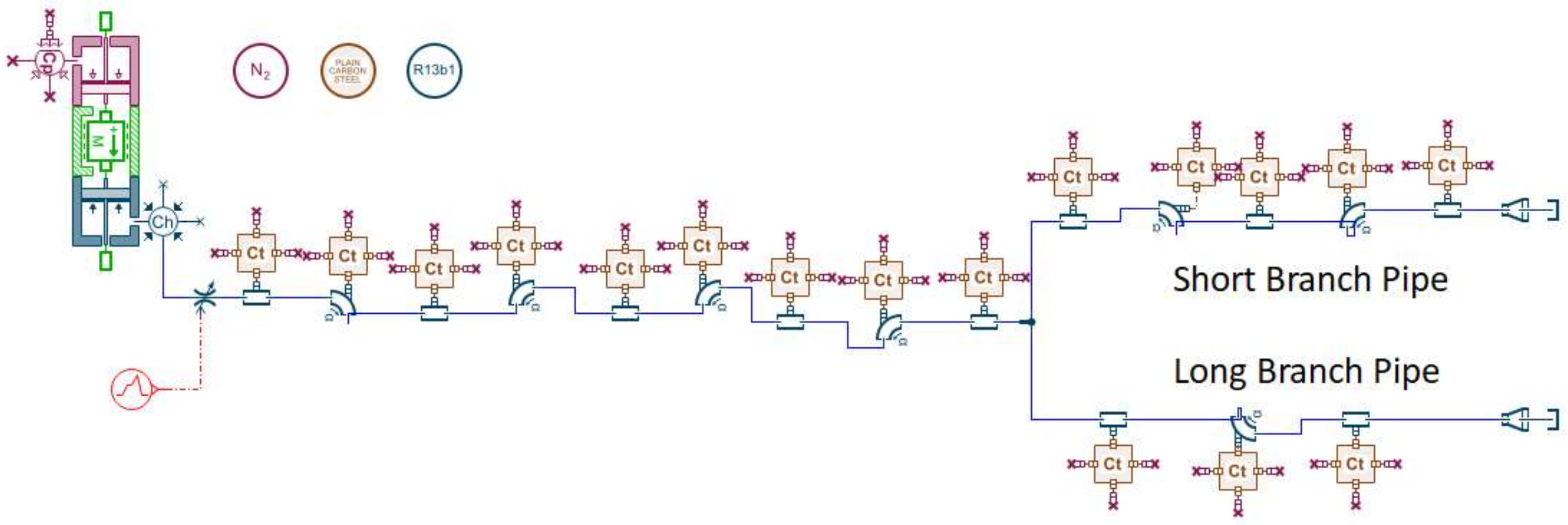
In this paper, a certain type of aircraft fire extinguishing system is used as the simulation object. The agent is Halon 1301, the volume of the cylinder is 7.0 L, the agent filling is 5.55 ± 0.2 kg, and the filling pressure is 4.2 MPa at room temperature. The pipeline of the fire extinguishing system can be classified into the main pipe and the branch pipe. The end of each branch pipe is connected with multiple nozzles. The pipeline structure is shown in
Figure 1.
2.2. Theoretical Model
The main flow form of Halon 1301 in the pipeline is unsteady gas–liquid two-phase flow. The state of Halon 1301 in the pipeline is defined by the Peng–Robinson equation [
23] applicable to gas–liquid two-phase fluid:
where
P is the absolute pressure, the unit is barA;
T is the fluid temperature, and the unit is K;
R is the ideal gas constant, its value is 8.314 J/mol K;
is temperature-dependent gravitational parameter;
Tc is the fluid critical temperature, the unit is K;
vc,
a,
b,
c, and
m are constants depending on Halon 1301.
Based on the above assumptions, without considering the gravitational pressure drop of Halon 1301 in the pipeline and ignoring the acceleration pressure drop, the flow pressure drop of Halon 1301 in the pipeline
can be expressed as the sum of the frictional pressure drop
and the local pressure drop
:
When there is single-phase flow in the pipeline, the frictional pressure drop can be expressed as:
where
Z is the length;
G is the mass flow velocity;
is the average velocity of the pipe and
f is the friction coefficient.
According to Churchill’s formula [
24] for laminar and turbulent flow, the friction coefficient
f can be expressed as:
where
Re is the Reynolds number;
D is the actual diameter of the pipeline;
ε is the absolute roughness of the pipeline.
When the agent flows in the pipeline, as the pressure decreases, Halon 1301 gradually boils, and then the flow pattern in the pipeline changes from single-phase to two-phase flow. At this time, the pressure drop
along the path can be calculated using the phase separation model [
25], the principle of which is a special interpolation between single-phase liquid and single-phase gas:
where
x is the gas mass fraction;
fL0 is the liquid phase friction coefficient;
fv0 is the gas phase friction coefficient;
vL is the liquid flow velocity;
vv is the gas flow velocity;
Dh is the hydraulic diameter.
The two-phase mass flow rate at the nozzle at the end of the pipe
can be expressed as
where
is the local pressure drop coefficient,
S is the cross-sectional flow area,
φ is the flow coefficient, and
is the coefficient of frictional resistance, and
is the density of the incoming flow, and
is the pressure difference between the two ends of the restriction, then the flow velocity
can be expressed as
2.3. One-Dimensional Simulation Model Establishment Parameters
This chapter uses the Amesim software of Siemens to simulate the flow of Halon 1301 in a certain type of aircraft fire extinguishing system. The agent Halon 1301 is described in the model based on the Peng–Robinson equation of state. The flow characteristics of the agent are calculated based on the two-phase flow library, and the heat transfer coefficient is defined based on the Nusselt number.
In the modeling process, the same assumptions are made as in the literature [
7]: 1. Nitrogen in the cylinder is incompatible with the agent; 2. Only the agent Halon 1301 flows in the pipeline, and the flow of nitrogen and air in the pipeline is not considered; 3. There is no relative slip between the two phases of the agent to maintain thermodynamic equilibrium; 4. The influence of gravity on the jet flow is not considered; 5. Only consider the heat exchange between the agent and the pipeline; ignore the heat exchange between the pipeline and the outside.
This software product is organized as follows: 1. Simplify the actual physical model: Simplify the geometric parameters of the actual physical model; 2. Build the component line: Model the component using the software’s built-in component library; 3. Assign the component model: Select a suitable sub-model for the component; 4. Set the component parameters: Set the boundary conditions and geometric conditions; 5. Set simulation conditions (time step, tolerance).
The built simulation model is shown in
Figure 2. The cylinder consists of a nitrogen piston, an agent piston, and a mass block representing the gas–liquid interface. The lengths of the two branch pipes are different. For the convenience of description, the two types of branch pipes are named as long branch pipes and short branch pipes according to their lengths. The agent starts discharging 1 s after the simulation starts. The straight pipes, elbows, solenoid valves, and nozzles in the pipeline are all set to contain flow resistance elements. In addition to its own phase change, Halon 1301 also exchanges heat with the pipeline to cause temperature changes. The initial value of the pipeline temperature is 20 °C. The downstream nozzle is directly connected to an infinite space; that is, the downstream boundary conditions of the flow model are constant pressure and temperature values of 1.013 barA and 20 °C, respectively. The multi-nozzle structure at the end of the branch pipe is simplified into a single expanding pipe with the same flow area.
It is worth noting that the model has the potential to be extended to other Halon substitute discharge applications, for example, HFC-125, when changing some of the above physical parameters such as critical temperature (Equation (3)), constants partially related to the agents (Equation (3)) and flow coefficient (Equation (11)).
2.4. Limitations of Model
The nitrogen in the cylinder is out of phase with the extinguishing agent. This assumption ignores the effect of the dissolved amount of nitrogen in the initial state and the possible pressure fluctuations in the tube caused by nitrogen precipitation during the discharge process, which then has an effect on the calculation of the flow rate. According to the study of Amatriain, A. [
26], the characteristic time of nitrogen precipitation is about 10–9 s, which has a small effect compared to the discharge time.
Only the extinguishing agent Halon1301 flows in the pipeline without considering the flow of nitrogen and air in the pipeline. When the height of the mass block describing the gas–liquid interface in the one-dimensional model is reduced to a minimum, the cylinder empties all Halon1301 enters the pipe, the nitrogen in the air gap in the model does not continue to escape, and the pressure at the outlet of the cylinder plummets from nitrogen pressure to Halon1301 vapor pressure. This assumption affects the change in pressure of the cylinder after the extinguishing agent has been discharged completely.
No relative slip between the two phases of the extinguishing agent maintains thermodynamic equilibrium. This term assumes a velocity ratio of 1 between the two gas–liquid phases and no temperature gradient between the gas and liquid, neglecting the high degree of imbalance at the leading edge of the flow, which has less impact on the calculation of the overall flow of the fire extinguishing agent.
The effect of gravity on the flow of the jet is not considered. This assumption ignores the effect of gravitational potential energy on the flow of the extinguishing agent in the line, which has less effect on the calculation of the energy change in the flow of the extinguishing agent, considering the high-pressure constraint in the cylinder.
Only the heat exchange between the extinguishing agent and the pipeline is considered, ignoring the heat exchange between the pipeline and the outside world. This assumption ignores the effect that the environment in which the pipeline is located, such as a high-temperature environment, may have on the flow of the extinguishing agent.
3. Analysis of Simulation Results
Based on the one-dimensional fire-extinguishing pipeline simulation model established in
Section 2, the effects of different filling pressures (2, 3, 4, 5, 6 MPa) and different initial temperatures (−50, −40, −30 °C) on the performance of the fire-extinguishing system are studied. Then, under the same filling conditions, the influence of the pipeline conditions of the aircraft fire extinguishing system on the discharge quality of the agent, the pressure of the cylinder outlet, and the flow distribution of the agent at each nozzle are investigated.
3.1. Effect of Filling Pressure
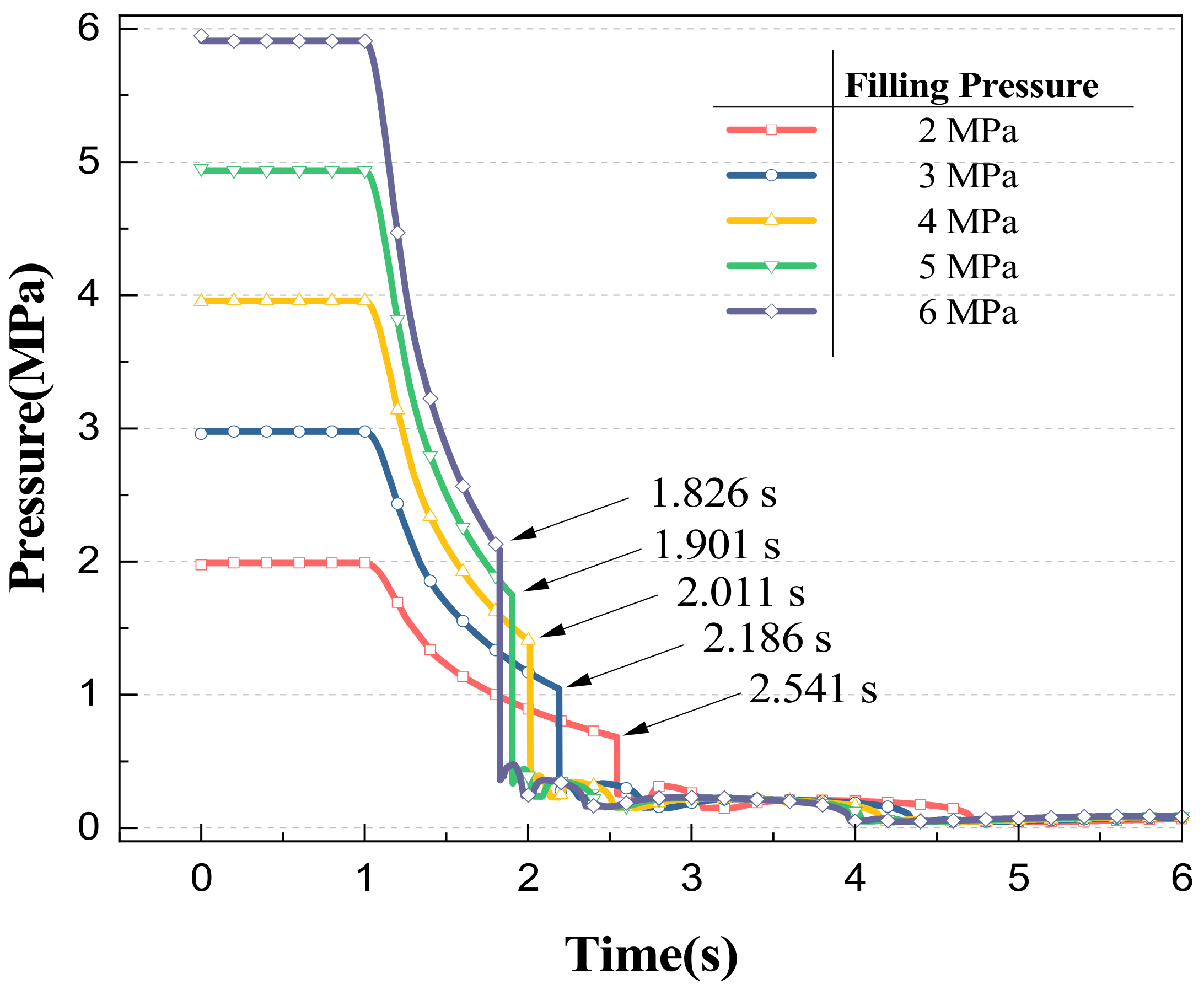
According to the change of cylinder outlet pressures over time under different filling pressures in
Figure 3, it can be seen that with the start of discharge, the cylinder outlet pressures at the initial stage decrease rapidly over time, and then the pressures drop sharply. Finally, the cylinder outlet pressure fluctuates gently and decreases to the environmental pressure. With the increase in the filling pressures, the pressure drop rate at the outlet of the cylinder accelerates at the initial stage, and then the pressures at the outlet of the cylinder plummet. The phenomenon of pressure drop is caused by the simplified hypothesis of the one-dimensional simulation model established in this paper. The simplified hypothesis (2) proposed in the second chapter of the paper is that only the agent Halon 1301 flows in the pipeline without considering the flow of nitrogen and air in the pipeline. When the mass height of the gas–liquid interface described in the one-dimensional model is reduced to the minimum, the cylinder is emptied, and Halon 1301 enters the pipe completely, nitrogen in the air gap in the model will not continue to be discharged, and the pressures at the cylinder outlet plummet from nitrogen pressure to Halon 1301 vapor pressure. The time between the start of the fire extinguishing agent discharge and the occurrence of a sharp drop in pressure is defined as the emptying time. The emptying time varies from 0.826 to 1.541 s with different filling pressures. Increasing the filling pressures can effectively shorten the discharge time of the agent, but with the increase in pressures, this effect will gradually weaken.
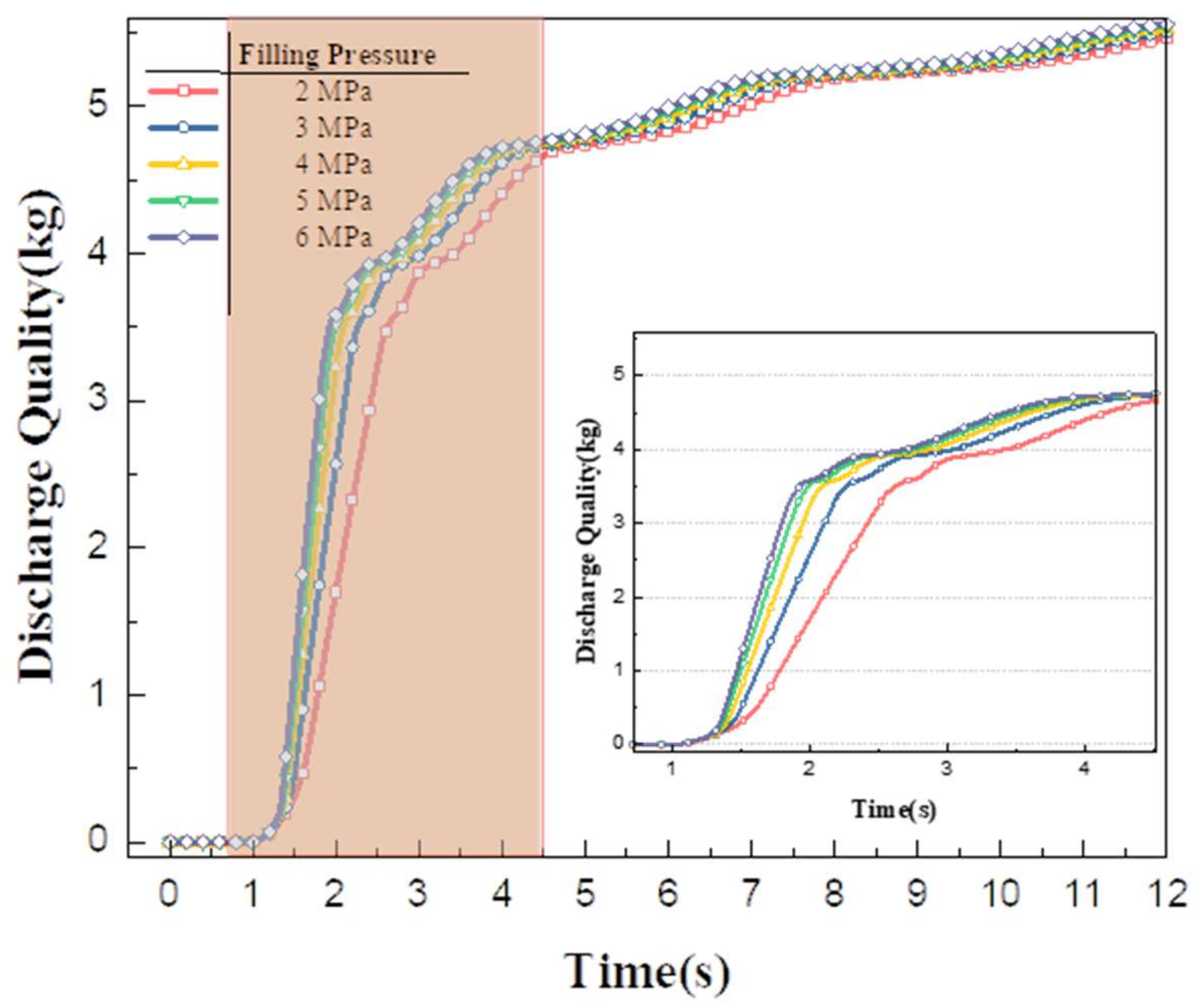
Figure 4 shows the discharge quality changes of the fire extinguishing system under different filling pressures. It can be seen from the figure that the discharging mass of the fire extinguishing system varies with time under different filling pressures. The mass of the agent discharged is 3.87, 3.98, 4.08, 4.16 and 4.21 kg, respectively, under 2–6 MPa filling pressure 2 s after discharge. Before 6 s, with the increase in discharge pressures, the total discharge quality of the two nozzles in the fire extinguishing system is higher, but the difference decreases with the increase in filling pressures, and the discharge quality curves of the three nozzles with filling pressures of 4, 5 and 6 MPa are close. The results also further verified that in the actual engineering design of the aircraft fire extinguishing system pipe network, the design filling pressure of the cylinder is 4.2 MPa, which can ensure the discharge rate and reduce the structural strength requirements of the cylinder.
Figure 5 shows the changes in pressures and mass flow rate at the nozzles of two branch pipes (long branch and short branch). On the whole, the trend of mass flow is similar to that of pressures. With the increase in discharge pressures, the maximum pressures and mass flow at the nozzle of the two tubes increase. The maximum pressures at the nozzle of the long branch pipe increase from 0.42 to 0.68 MPa, and the maximum mass flow rate increases from 0.6 to 1.67 kg/s. The short branch nozzle is more sensitive to changes in initial pressures. The maximum pressures at the short branch nozzle increase from 0.49 to 0.83 MPa with the increase in initial pressures, and the maximum mass flow rate increases from 2.70 to 4.68 kg/s.
3.2. Effect of Initial Temperature
As the flight height of the aircraft increases, the ambient temperature of the aircraft decreases, which will affect the filling state of the cylinder [
27,
28]. In an airworthiness test, the initial temperature is required to be about −55 °C. According to the ideal gas equation, on the premise that the filling nitrogen mass remains unchanged, the decrease in temperature will lead to a decrease in the pressure in the cylinder, thus affecting the fire extinguishing system. Therefore, compared with the surface, the low-temperature environment in the air is more unfavorable to the discharge of the agent. In this paper, the initial temperature of the cylinder is −50, −40 and −30 °C, respectively, and the discharge behavior of the fire extinguishing pipeline is studied.
The filling pressure
in the cylinder can be expressed as the sum of Halon 1301 saturated vapor pressure
and nitrogen partial pressure
in a stable state.
The saturated vapor pressure
of Halon 1301 can be calculated using the empirical equation based on the Antoine formula [
29]:
where
A,
B,
C,
D and
E are constants related to Halon 1301,
T is absolute temperature, K.
Assuming that nitrogen follows the ideal gas equation [
26], the partial pressure of nitrogen
can be expressed as:
where
n is the quantity of nitrogen substance,
R is the ideal gas constant, and
is the volume of nitrogen.
Ignoring the volume change of nitrogen in the cylinder caused by temperature,
is a constant set as
F, and the pressure
in the cylinder can be expressed as a function of temperature:
In the formula,
is a constant related to nitrogen quantity, which can be calculated by measuring the temperature and pressure in the actual cylinder in a stable state. It is known that the filling pressure in the cylinder is 4.2 MPa at 22 °C, and when the cylinder is frozen to −55 °C, the pressure in the fire extinguishing cylinder is measured as 2.63 MPa, and
F can be calculated as 0.011545 MPa/K. The temperature and pressure in the cylinder and the saturated vapor pressure of the corresponding agent at different temperatures were calculated, respectively, as shown in
Table 1.
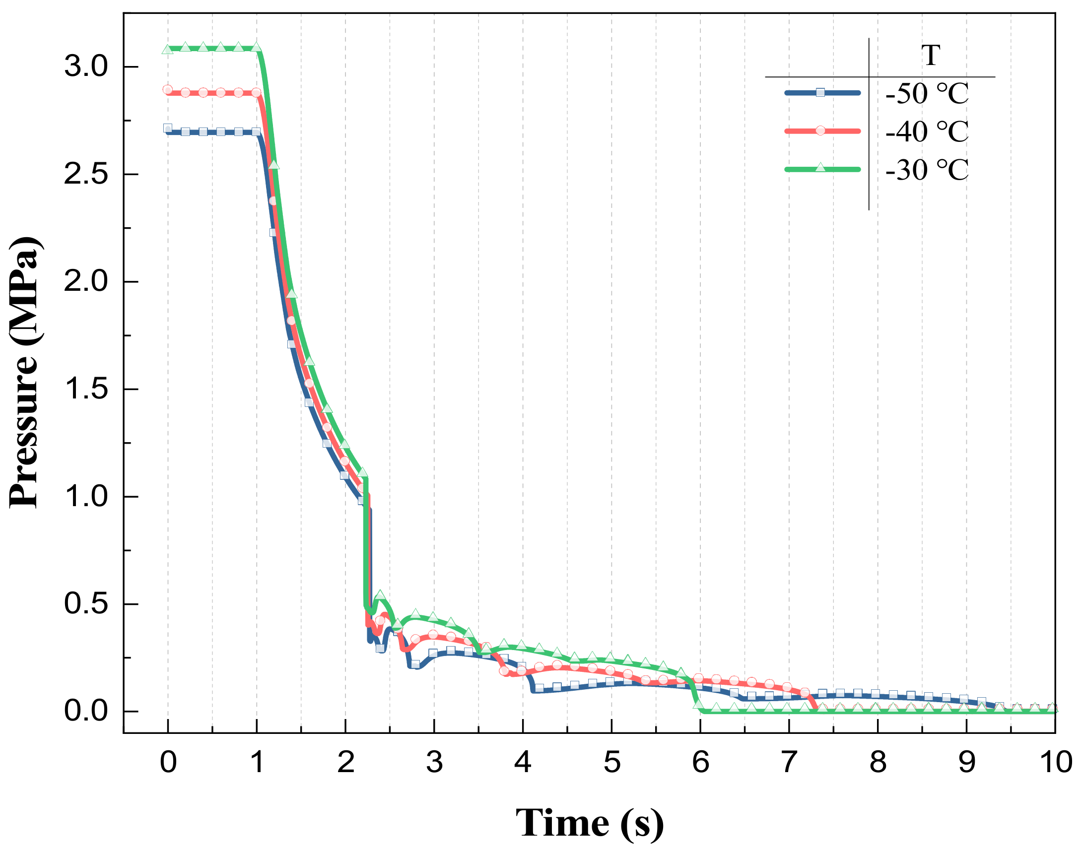
Figure 6 shows the change of cylinder outlet pressure at different initial temperatures. Different initial temperatures correspond to different initial pressures in the fire extinguishing cylinder. The lower the initial temperature is, the lower the initial pressure in the fire extinguishing cylinder is and the slower the pressure drop rate. This result is consistent with the analysis in
Section 3.1. Under different initial temperatures, the discharging time of the agent in the cylinder is close, about 1.22 s, but the discharging pressure of the cylinder outlet is inconsistent, which is caused by the inconsistent temperature of nitrogen in the cylinder when the mass block height drops to the lowest. When the cylinder is emptied, according to Equation (14), the steam pressure of Halon 1301 depends on the temperature; the higher the initial temperature, the higher the pressures at the outlet of the cylinder after plummeting.
Figure 7 shows the change in discharge quality of the agent at −50, −40 and −30 °C. When the agent is not drained from the cylinder before 2.22 s, the mass of the agent discharged from the fire extinguishing system at the three initial temperatures is similar, about 3.19 kg. With the increase in time, the mass flow rate of the fire extinguishing system at the three initial temperatures begins to decrease. The lower the initial temperature is, the more obvious the effect of mass flow reduction is. The reason for this effect is that the difference in steam pressure of the agent caused by different temperatures leads to the inconsistency of the corresponding time when the final system reaches the maximum discharge mass. The higher the initial temperature is, the shorter the time the system can discharge all the agents, so the elevation of the aircraft’s flight height is not conducive to the work of the aircraft fire extinguishing system.
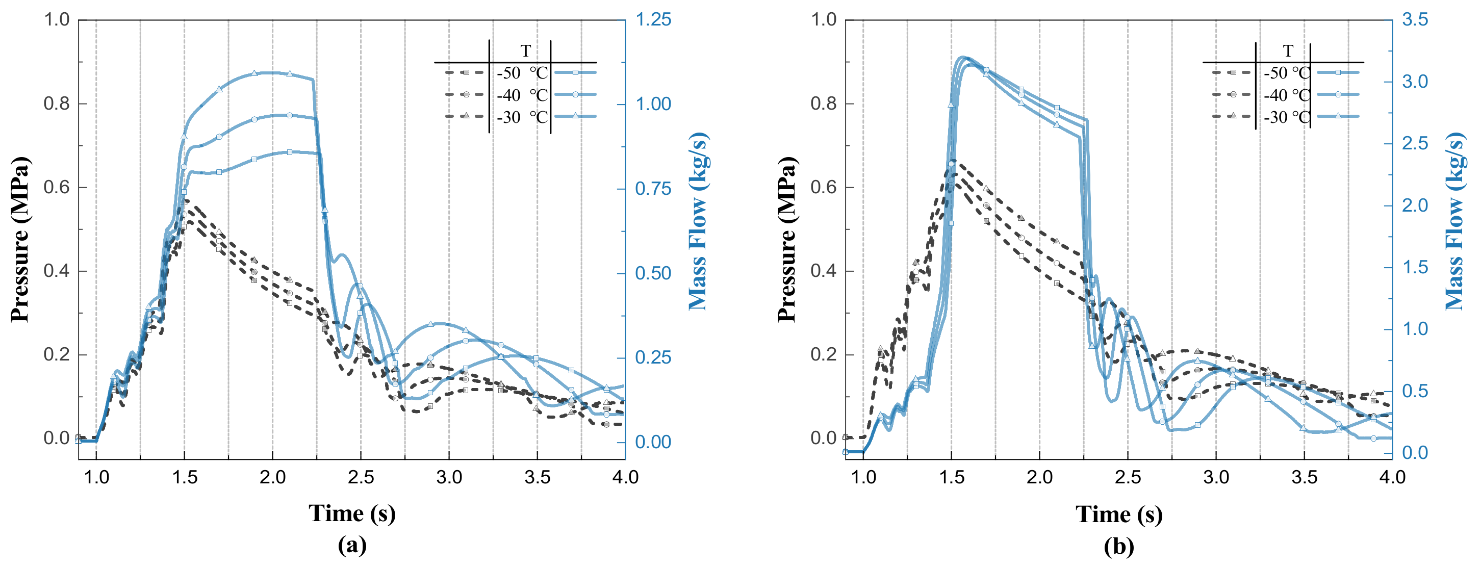
Figure 8 shows the variation of pressure and mass flow rate at the nozzles of the two branch pipes for different initial temperatures. The pressure at the nozzle rises to a maximum after the start of discharge, at which point it enters the high mass flow discharge phase, with the mass flow rate remaining in a high range of fluctuations, and as the discharge continues until about 2.2 s, the mass flow rate begins to decrease, and the high mass discharge phase ends. As the initial temperature increases, the pressure at the nozzles of both branch pipes increases. The mass flow rate changes in a different pattern; as the initial temperature increases, the maximum mass flow rate at the long branch nozzle increases, and the maximum mass flow rate at the short branch nozzle decreases. At different initial temperatures, the duration of the high mass flow discharge phase is similar for both branch pipes.
The mass flow rate at the long branch nozzle is more sensitive to changes in temperature, and in the high mass flow discharge stage, the two branch nozzle mass flow rate maximum shows an opposite change pattern, which will inevitably bring about differences in flow distribution, with the initial temperature increase, the long branch nozzle discharge mass increases while the short branch discharge mass decreases, and the total discharge remains the same.
3.3. Effect of Pipeline Roughness
According to Equation (6), it can be seen that the absolute roughness of pipeline affects the flow of the agent pipeline by influencing the friction coefficient . Under the filling condition of a 5.55 kg agent and 4.2 MPa filling pressure, the flow of Halon 1301 under different kinds of roughness is simulated by modifying the absolute roughness of the pipeline to 0 mm (ideal smooth round pipe), 0.13, 0.2, 0.3 and 0.5 mm respectively.
The influence of different absolute roughness on the pressure of the cylinder outlet is shown in
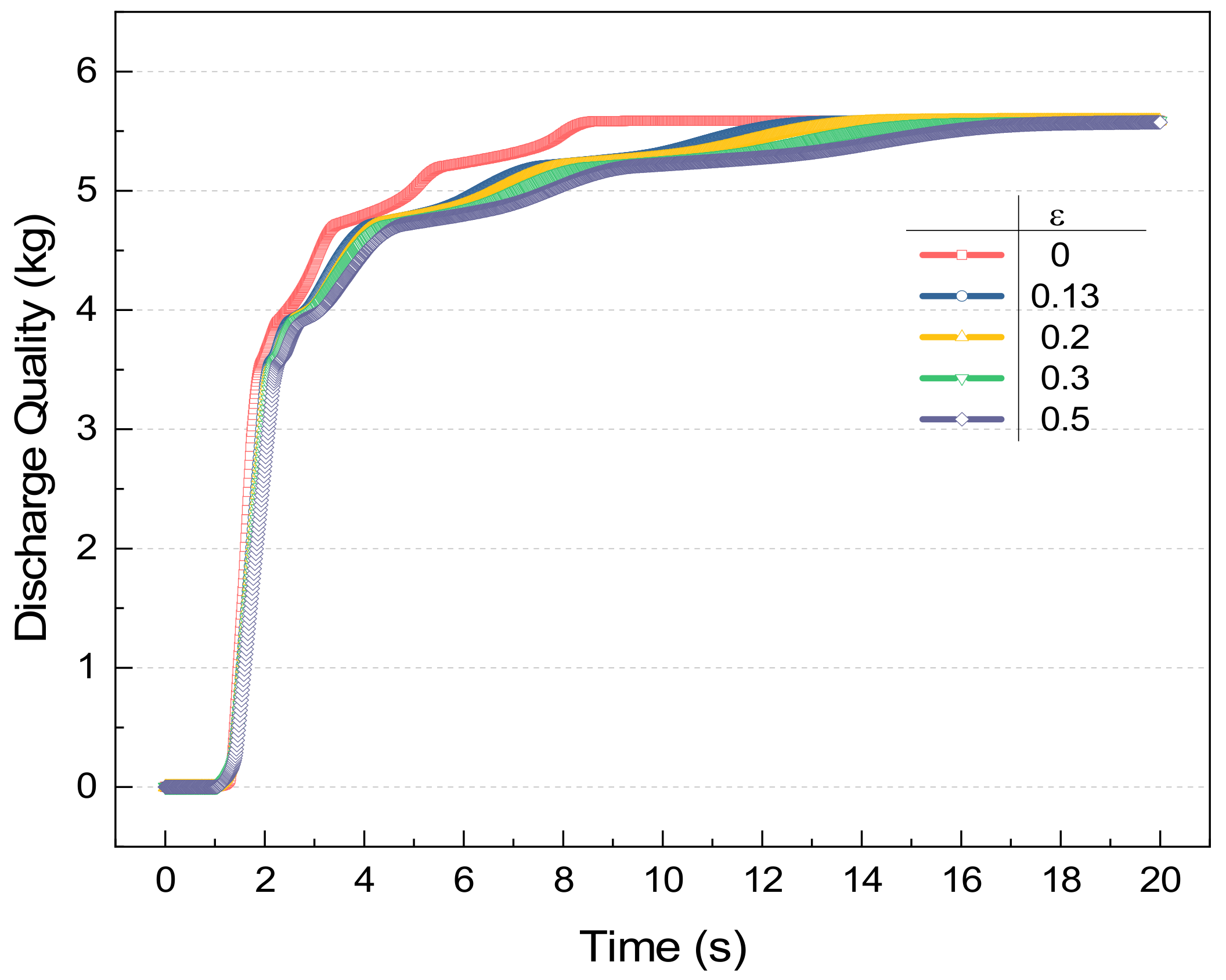
Figure 9. It can be seen that the absolute roughness of the pipeline affects the outlet pressure change of the upstream cylinder; when the absolute roughness is smaller, the smoother the pipeline is, the faster the pressure change of the cylinder outlet under the ideal smooth round pipe (ε = 0 mm), the emptying time of cylinder is 0.72 s, while when ε = 0.5 mm, the emptying time is 1.15 s, emptying time increased by 59.72%. The pressure at the outlet of the cylinder before the pressure drop is defined as the evacuation pressure. When the cylinder is emptied, the volume change of nitrogen in the nitrogen piston is consistent, and the pressure change is consistent, so the emptying pressure is close under different roughness.
According to
Figure 10, the absolute roughness of the pipeline also has an impact on the discharge mass of the fire extinguishing system; in the ideal smooth round pipe, the agent only needs 7.43 s of all of the pipeline to discharge. When the absolute roughness of ε = 0.5 mm, it takes nearly 16 s to discharge the agent all out. When the absolute roughness increases from 0.13 to 0.5 mm, the time of all agent discharges increases from 12 to 16 s, and the total discharge mass remains the same. Therefore, in engineering design, in order to improve the fire extinguishing system discharge effect, we should try to reduce the absolute roughness of the pipeline.
3.4. Effect of Main Pipe Diameter
Compared with the branch pipe, the main pipe diameter and longer length is the main component of the fire suppression system piping, this section explores the impact of increasing or decreasing the diameter of the main pipe for the flow of agent.
The change of pressure of cylinder outlet with different main pipe diameters is shown in
Figure 11; increasing or decreasing the diameter of the main pipe has no obvious effect on the emptying pressure inside the cylinder, and the emptying time decreases with the increase in the diameter of the main pipe, and the shortest emptying time is 0.89 s when the diameter of the main pipe is 20 mm. Increasing the pipe diameter can improve the rate of agent discharge, but it also needs to take into account the increased volume and weight of the extinguishing system.
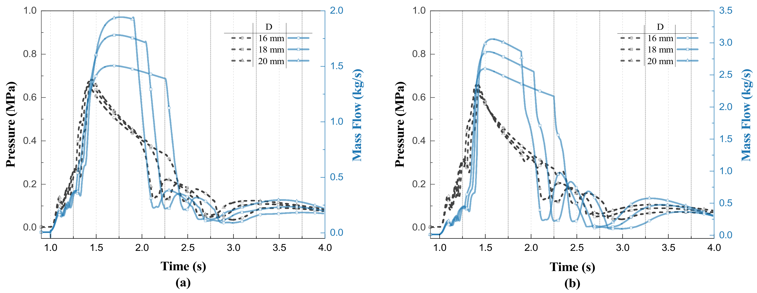
The pressure and mass flow rate at the two branch nozzles under different main pipe diameters are shown in
Figure 12, and the main pipe diameter has a small effect on the pressure at the two branch nozzles. The maximum pressure at the long branch nozzle increases with the increase in the diameter of the main pipe, and the maximum pressure at the short branch nozzle changes in the opposite direction. The maximum mass flow rate at both nozzles increases with the increase in the diameter of the main pipe, the maximum mass flow rate at the long branch nozzle increases from 1.50 to 1.94 kg/s, and the maximum mass flow rate at the short branch nozzle increases from 2.59 to 3.05 kg/s. With the increase in the diameter of the main pipe, the duration of the high mass flow discharge phase decreases, and you can achieve an increase in the diameter of the main pipe. The conclusion is that it is conducive to improving the efficiency of agent discharge.
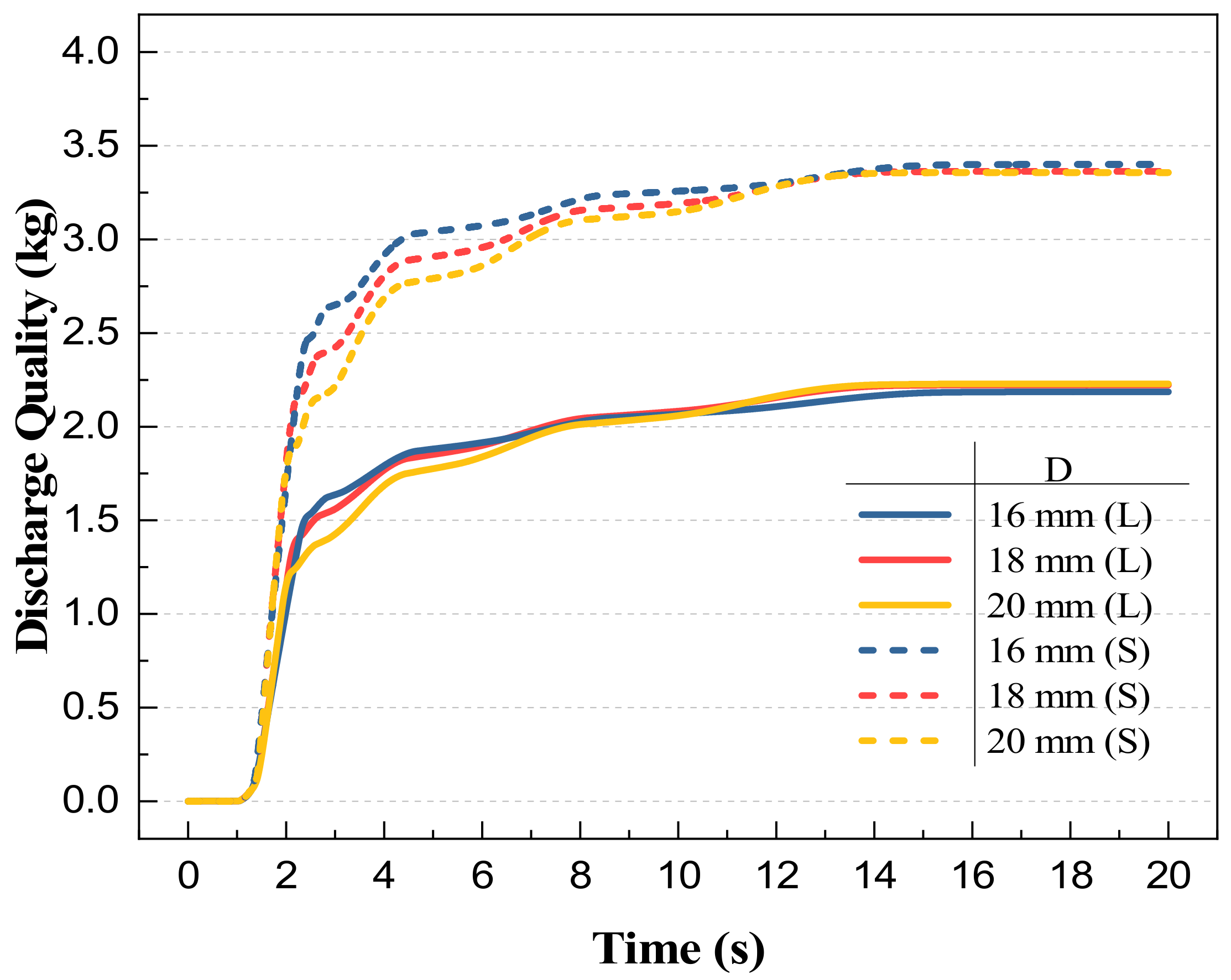
According to
Figure 13, as the diameter of the main pipe increases, the maximum value of mass flow rate at the nozzles of the two branch pipes increases, the duration of the high mass flow discharge phase decreases, and the discharge mass of both branch pipes increases with the diameter of the main pipe in 1–8 s. The size of the main pipe diameter also affects the flow distribution between the two branch pipes; in the case of the main pipe diameter of 16 mm, the total discharge mass of the short branch increases, and the total discharge mass of the long branch decreases, and the total discharge mass remains unchanged.
3.5. Branch Pipe Diameter Analysis
According to the pipeline structure model shown in
Figure 2, the length of the two branch pipes is different; according to the results of the two branch pipes’ nozzle flow in
Section 3.2, it can be seen that the difference between the two nozzles at the discharged mass is large, in 4.2 MPa filling pressure, the short branch nozzle discharge mass is more than the long branch discharge mass of about 2.468 kg.
In order to make the concentration of agents in the target protection nacelle more balanced, it is necessary to adjust the flow resistance of the two branch pipes to influence the distribution of agents and thus achieve the purpose of balancing the flow rate. In the case of a compact and fixed aircraft, it is easier to adjust the branch pipe diameter rather than the branch pipe length [
11]. Therefore, the results of different branch pipe diameters are investigated for the flow distribution.
Route 1: increase the long branch pipe diameter to reduce the long branch pipe flow resistance; Route 2: reduce the short branch pipe diameter to increase the short branch pipe flow resistance. According to these ideas, set up a total of five simulation scenarios, different scenarios in the long and short branch pipe diameter, as shown in
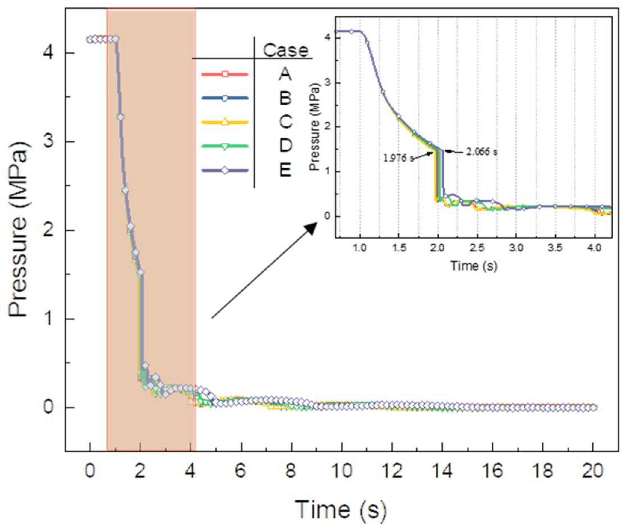
Table 2.
The values of the long and short branch diameters and the discharge masses and their mass ratios for the corresponding pipe diameters are given in
Table 2 for a total of five scenarios. Scene A is the initial scenario corresponding to the branch diameter; from the table, it can be found that increasing the long branch diameter has less effect on the equilibrium flow than decreasing the short branch diameter. When the diameter of the short branch pipe is reduced to 10 mm, the mass ratio of long and short branch pipes reaches 0.979, and the flow rate is close to the same, which can achieve the purpose of balancing the flow rate while reducing the system weight.
As shown in
Figure 14, the influence of different branch pipe diameters on the pressure at the cylinder outlet is small, and the emptying time grows from 0.976 s in scene C to 1.066 s in scene E. After the cylinder is emptied, the pressure of the cylinder outlet fluctuates due to the heat exchange between the pipe and the agent. The larger the diameter of the long branch pipe, the faster the pressure change at the cylinder outlet, and the smaller the diameter of the short branch pipe, the slower the pressure change of the cylinder outlet. Scene E to achieve balanced flow and reduce the weight and volume of the fire suppression system while the impact on the discharge time is small. The results of the section for the fire extinguishing system branch pipe diameter design are of guidance.
4. Conclusions
Amesim software was used to establish a simulation model of an aircraft fire extinguishing system piping, to study the influence of fire extinguishing cylinder filling conditions and piping conditions on the performance of the fire extinguishing system under 5.55 kg of agent filling, and the following conclusions were obtained.
(1) The change in the filling conditions of the fire extinguishing cylinder to the change in the pressure of the cylinder itself, which in turn affects the pressure and mass flow rate of the agent at the nozzle. The higher the filling pressure, the faster the pressure drop; 4, 5, 6 MPa filling pressure under the agent discharged mass curve is similar; with the initial temperature decreases, the pressure at the cylinder outlet decreases, and the emptying time is similar to 1.22 s, but the difference between the discharge mass to reach the peak point is larger.
(2) Under the same filling conditions, roughness affects the flow of the agent by affecting the friction coefficient; the lower the roughness, the faster the discharged agent, but the total mass discharged from the fire extinguishing system under the pipeline thermal boundary conditions is close; when the short branch pipe diameter is 10 mm, and the long branch pipe diameter is 14 mm, the two branch pipe discharge mass ratio is close to 1, which makes the concentration of the agent in the target protection nacelle more balanced. Changing the branch pipe diameter has less effect on the emptying time; the larger the main pipe diameter, the larger the diameter of the main pipe, and the higher the discharge rate, but the actual design requires comprehensive consideration of the energy costs associated with the increase in the diameter of the main pipe.
Although this research was conducted with Halon 1301, the main value of this paper is to optimize the system design and reduce the potential use of Halon 1301 during aircraft design and in actual aircraft firefighting and to provide a research methodology and comparative benchmark for subsequent pipe flow studies and applicability studies of a Halon substitute.

