Review

Experimental and Numerical Analysis of Formation and Flame Precession of Fire Whirls: A Review

by
Maryam Ghodrat
1,*,
Farshad Shakeriaski
1,
David James Nelson
2 and
Albert Simeoni
3
1
School of Engineering and Information Technology, University of New South Wales Canberra, Canberra, ACT 2610, Australia
2
School of Aerospace, Mechanical and Mechatronic Engineering, The University of Sydney, Camperdown, NSW 2006, Australia
3
Department of Fire Protection Engineering, Worcester Polytechnic Institute, Worcester, MA 01609, USA
*
Author to whom correspondence should be addressed.
Submission received: 12 July 2021 / Revised: 1 August 2021 / Accepted: 3 August 2021 / Published: 6 August 2021
(This article belongs to the Special Issue Wind Fire Interaction and Fire Whirl)

Abstract

:
Fire whirls are a particular case of flame behaviour characterized by a rotating column of fire driven by intense convective heating of air close to the ground. They typically result in a substantial increase in burning rate, temperature, and flame height. Fire whirls can occur in any intense flame environment, including urban areas, particularly within combustible structures, and in wildland or forest fires. Recently, investigations on the creation of fire whirls have attracted much attention. However, most analyses are focused on fire whirl structure, formation, and controlling their unique state. In effect, revisiting the available experimental techniques and numerical simulations used in analyzing fire whirls has received less attention. In this paper, experimental arrangements including empirical set ups and employed fuels are presented in detail. Subsequently, major research progress focused on experimental studies and their laboratory setup is fully discussed, followed by the available numerical simulations, including combustion and turbulence models. Applied methodologies and chosen software in the recent numerical studies are also reviewed exclusively. Finally, the latest findings are featured, and prospective pathways are advised.

1. Introduction

A fire whirl is a unique concentrated vortex driven by and consisting primarily of combustion processes and products [1]. Fire whirls are rare but can be catastrophic and are formed in instances where intense flames produce significant vertical convective currents in the presence of a local rotation of the surrounding air near the fire base [2]. The most prominent fire whirl event occurred in Japan during the Kanto earthquake of 1923 [3]. In this incident, the fire whirl reached one hundred meters in height and caused the death of about 38,000 people. Scientists and researchers in Canberra reported that they have observed the first instance of a fire tornado from the investigation of the evidence gathered from the January 2003 Canberra fires. Approximately 70 percent of the Australian Capital Territory’s nature park, pine plantations, and pastures were seriously destroyed, and most of the Mount Stromlo Observatory was damaged [4]. Because fire whirls produce a strong intensification of combustion and the risks they pose during large wildland fires, the necessity of studying this phenomenon is obvious. In this regard, many different studies have been conducted to explore the behavior of fire whirls from different extents. However, the need to review governing equations, up-to-date proposed models, and solution methods for fire whirls is essential. This paper is aimed to review the available simulation methods and discusses the capability and competency of such methods. First, a summary of the fundamentals, classification, and formation mechanism of fire whirls is given. Then, the experimental arrangements and numerical simulation techniques, including combustion and turbulence models, are presented. The review finally classifies the research that are conducted thus far based on their simulation methods and techniques to examine the behaviour of fire whirls.

2. Fire Whirl Phenomenon

2.1. Definition, Classification, and Formation Mechanism

Fire whirls are a type of standing vortex stimulated under specific air entrainment conditions, where circular movement is developed by the arriving flow and forms a flame rotation near its center core [5]. Fire whirls are not exclusively formed of fire, as several fire whirls have been observed which consist of hot gases formed downwind of fires (Figure 1a) [6]. Fire whirls are formed due to the interplay between fire fuels, with distinctive impacts including cross stream and vortex breakdown. Some of them are created from multiple fires with no wind. There are three main processes involved in the structure of fire whirls: (1) an eddy production process (vorticity), (2) a surface drag force to produce a radial boundary layer, and (3) a thermally driven fluid sink [2]. It is possible to have intensive eddies including shear forces and fluid sinks at the base coalesce within fires [7,8]. The scorching gases produced by the fire act as a fluid sink, pulling the surrounding air with an angular motion from the eddy vorticities to the core of the flame [9]. The rotation in the air that gathers up into the fire whirl can come from various sources, including wind dragging along the ground (see Figure 1c,d). The burning gases in the fire plume heats up the air so that it accelerates upward, stretching and consolidating the fire whirl into long, thin tubes (See Figure 1b). Fire whirls are well-categorized and can be separated into three major types [10].
Type 1. Stationary, on-source (formed directly over the fuel source), and reacting [11]. (Reacting fire whirls consist primarily of combusting materials, while non-reacting whirls consist of non-combusting materials and gases).
Type 2. Unsteady, on-source, and reacting with periodic shedding. Formed when a line fire is subject to angled crosswinds.
Type 3. Off-source and can be reacting or non-reacting.
When the rotating vortex column is created right over the fuel source, the fire whirl is identified as “on source”, and once it moves away or is offset to the fuel surface, it is identified as “off source” [13]. The formation of a fire whirl begins with a ground fire producing a convective updraft of hot gases, including air and combustion products. This produces a low-pressure area just above the flame that pulls in ambient air. In the event of a crosswind or rotating wind, the vorticity of the column of combustion gases is increased as the lateral momentum of the wind is converted to angular momentum centered at the low-pressure zone. In fire whirls, this effect is intensified by means of vortex dragging due to the strain field formed by the rising air [14,15]. The combination of effects creates a concentrated vertical vortex core characteristic of a fire whirl (as shown in Figure 1c).

2.2. Source of Vorticity

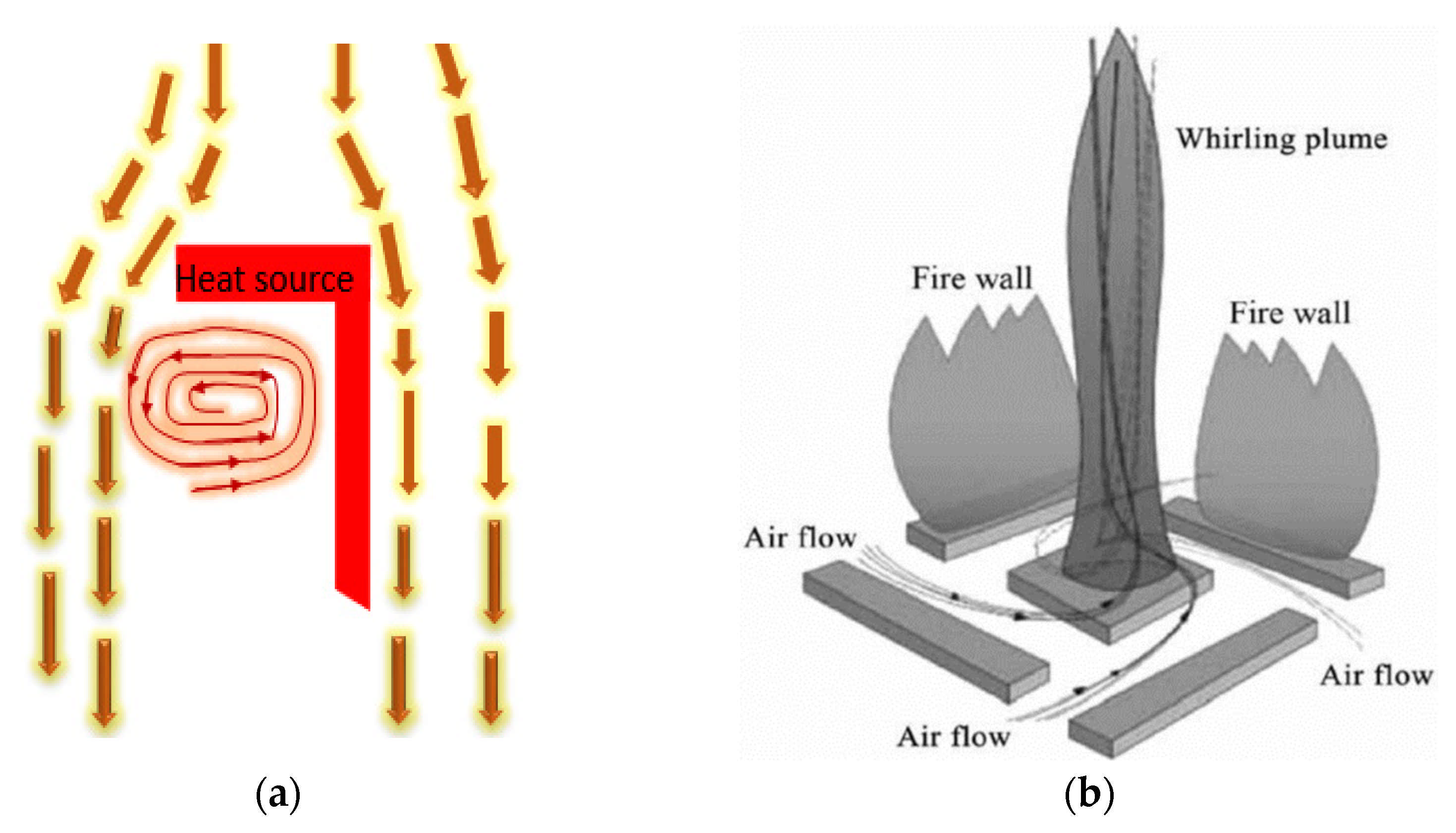
There are various potential sources of ambient vorticity that can cause fire whirls to form. One key source is the shear layer, which develops when ambient wind flows over the ground, creating horizontally leaning vorticity. This horizontal vorticity can then be rearranged, or tilted, by the fire’s buoyant flow and turned to the vertical axis, becoming a key contributor to various fire whirls. Equally, it is expected that the inflow generated by a buoyant plume forms a shear layer closer to the ground, which also creates horizontal vorticities. These horizontal vorticities can be tilted or reoriented to the vertical (Horizontal vectors change direction to vertical vectors) (Figure 2). This source of vorticity could be present even in no wind situations. Complex topography (Wildland–urban interface (WUI) with manmade structures) can also form vorticity through phenomena such as channeling, a shear of ambient and fire-induced winds [16]. Other sources of vorticity are shown in Figure 3 and Figure 4, including fire whirls that form inside the bend of an L-shaped heat source in crossflow [17] (Figure 2a) and fire whirl that occur due to the interaction of multiple fire plumes with no crossflow wind (Figure 2b).
Numerous observations of fluid dynamics phenomena happening in large-scale pool fires, particularly fire in the existence of wind, have been described by Tieszen et al. [18], who asserted that baroclinic vortex generation is especially prominent for large-scale pool fires. The misalignment of the pressure gradient from the density gradient is referred to as the baroclinicity at a point. Typically, the gradients of density and pressure act on the same axis, but the conditions close to a fire sometimes result in warm air rising due to surrounding cold air, producing two disparate local strata. Air above the fire extends and lines of constant density (called isopycnals) are formed. The colder surrounding air has a greater density compared to the fire area, tilting the isopycnals towards the fire area. The tilting of isopycnals and isobars in the contrary axis is a baroclinic resource of vorticity, as both gradients influence the fluid. These produce forces acting in different axes, resulting in a rotation and leading to the generation of baroclinic vorticity. Fire whirls can form from relatively small fires under suitable wind or topographic conditions such as at the WUI with artificial structures. Laboratory-scale tests have illustrated that an approximately stationary pool fire might produce a fire whirl, resulting in a much larger burning rate and temperature compared to the primary fire [19,20,21]. This transient occurs in the model as the fire is tilted to one side first, commences to spin, and afterwards pulls upward prior to forming a fire whirl. The flame heights from pool fires and fire whirls can vary from centimeters to kilometers [22].

3. Experimental Arrangements (Experimental Setup, Fuels, and Burning Behavior)
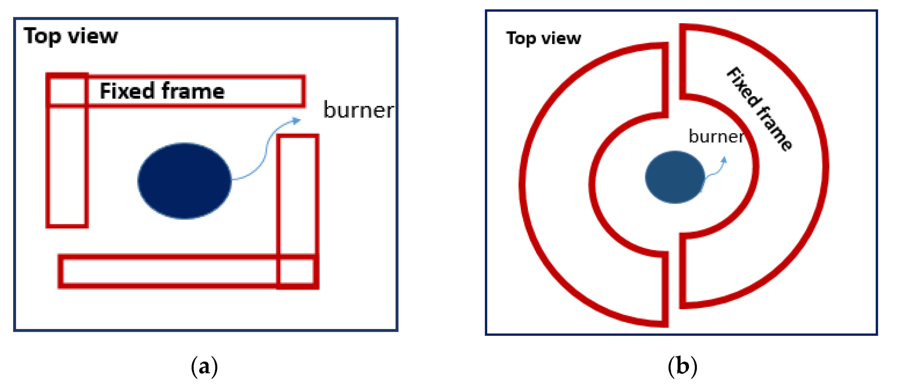
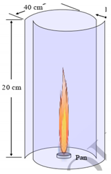
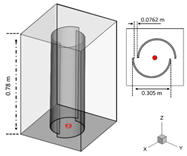
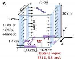
The modeling tests of fire whirl are conducted based on a burner-type laboratory fire whirl. The tests are performed by a mechanism including a support flame, a burner, a bed, and a mechanical wind wall. Both the pool fire and burner might be applied to produce buoyancy [23,24]. The whirls can be formed using the constant frame technique. Some constant-frame-type whirl generators consist of a pair of L-shaped covers (see Figure 3a) [2]. The covers are set to produce a swirling stream by means of entrained air. In addition, the whirls can be created using the constant frame technique, that is, cylinder halves symmetrically staggered around a burner which is flush to a basis sheet to produce the background vorticity (see Figure 3b) [25].
In the constant frame technique, the fire strength can either alter or be constant. In fact, the chosen geometry specifies the swirl strength. Moreover, both the fire strength and the imposed circulation can be determined. In all conditions, the thermal release rate is controlled by regulating the fuel mass flow rate [26].
To analyze fire whirls in the laboratory, several types of fuels are employed. Liquid, solid, and gas fuels can be utilized to analyze the behavior of fire whirl, each with their own advantages and disadvantages. Test fuels may either be fed into the system during the test or located at the container’s center for a certain burning period. Solid fuels must be set in place prior to ignition, while gas fuels must be fed in. Liquid fuels can utilize either method. Chauh et al. [27] employed a fuel pan for inclined fire whirl tests using methanol, two-propanol, and ethanol as fuel. Aluminum slits were used in some tests to keep the fuel surface coplanar to the surrounding surface.
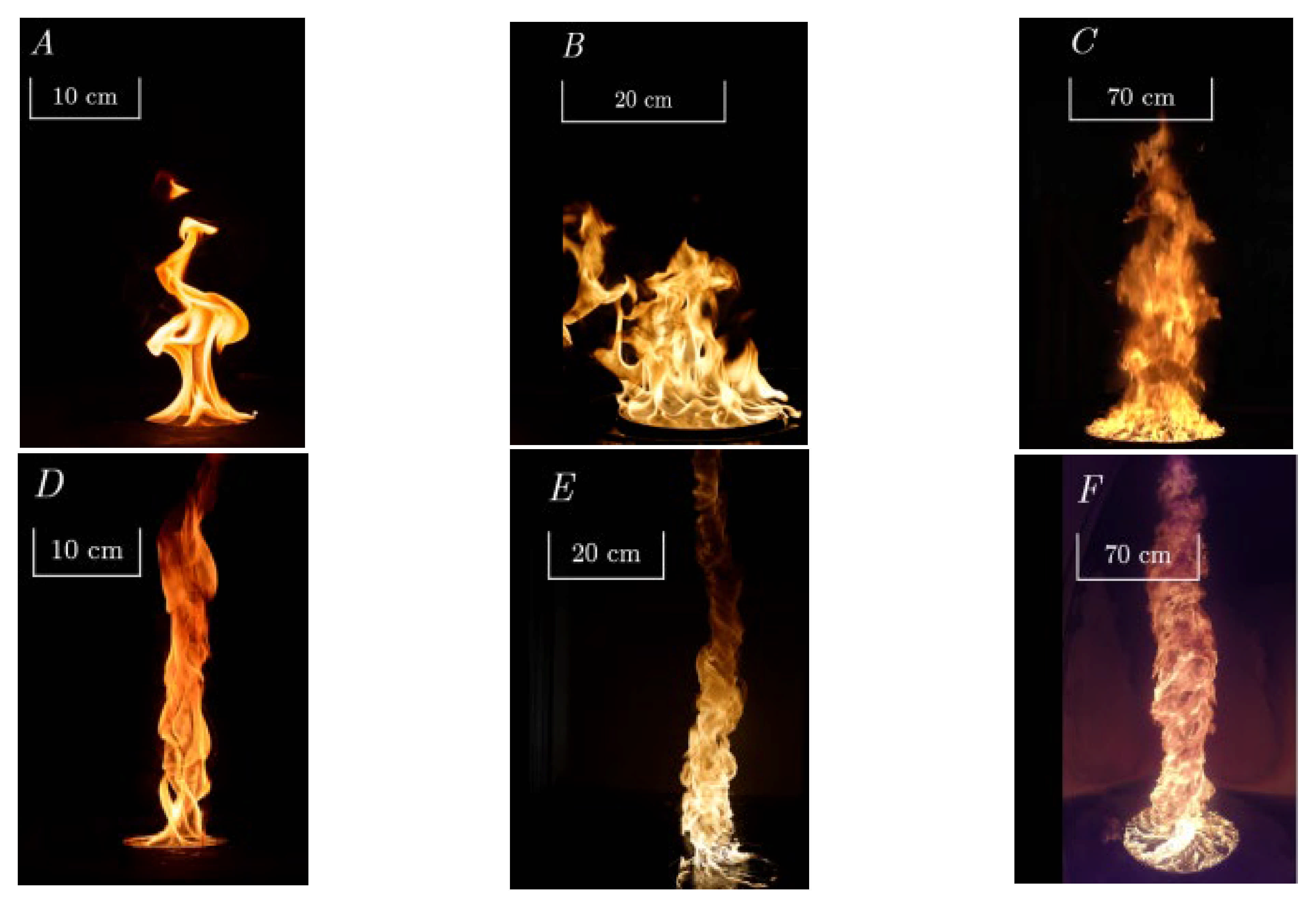
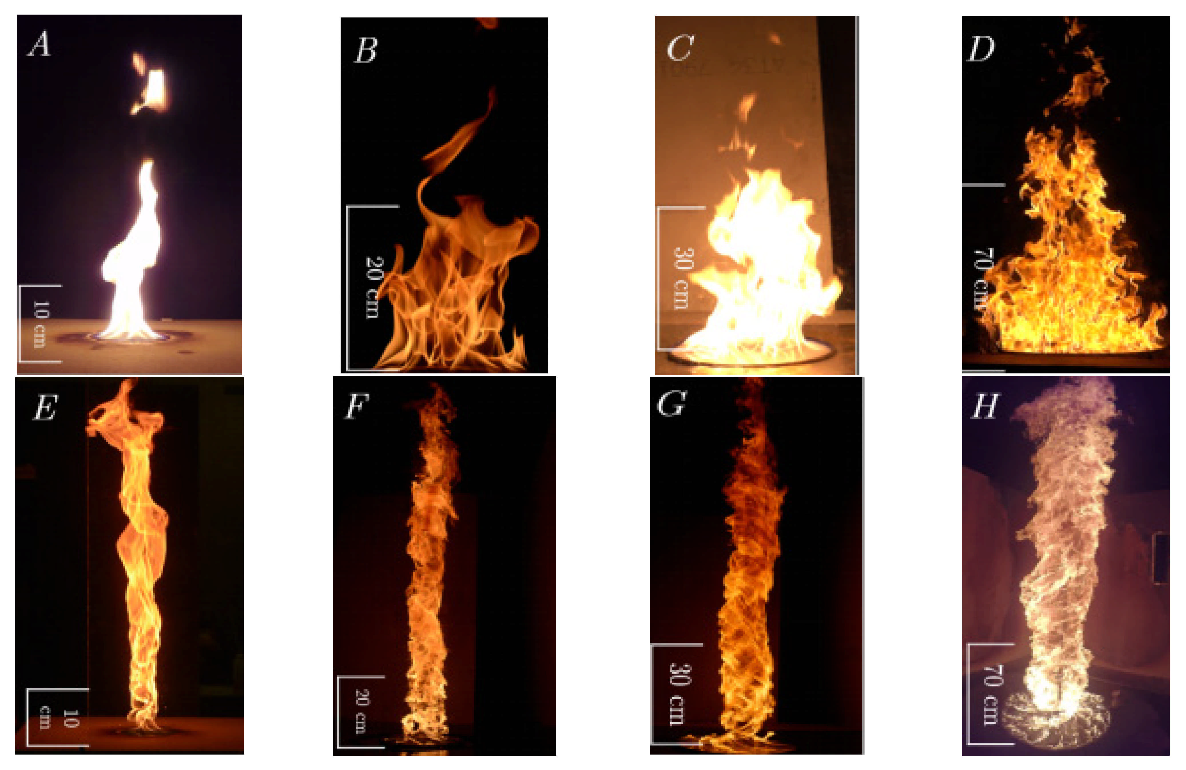
In the context of burning behavior, some small-scale empirical analyses were conducted to find correlations between the flame length, burning rate, and the fuel type used. Semi-experimental simulations coupling the rates of burning with the ambient circulation and the pool size for turbulent and laminar fire whirls including liquid fuels were presented by Lei et al. [28]. The authors asserted that the growth of the burning rate in this phenomenon is due to the increased convective mass and heat transfer in the inflow boundary layer above the surface of the liquid fuel. An empirical analysis to investigate the burning rate of various fuels in fire whirls and pool fires was conducted by Hariharan [29]. Experiments were done using two types of fuel, Alaska North Slope crude oil and n-heptane. The authors used pool fire. A constant-frame, four-wall configuration was used to produce the fire whirls. The four walls were positioned to form a container, and the fuel pool was located at the container’s centre on the bottom face. This setup allows the natural entrainment of air to the fire via the four gaps, forming an on-source, quasi-steady fire whirl. To produce a pool fire, the walls were picked up to allow radially symmetric air entrainment to the fire. A circulate dish formed of aluminium was applied to include the fuel pool. The dish was applied to keep a water sublayer upper which the fuel slick floated, mimicking open-water conditions at the laboratory scale. The resulting flames are shown in Figure 4 and Figure 5. For tests with heptane fuel (see Figure 4), the total mass loss was equal to both fire whirls and pool fires, as no residue remained behind following extinction. The mass loss can be considered linear for heptane fire because the rate of mass change is constant over time; however, the rate decreases over time for Alaska North Slope fires (see Figure 5).
Figure 4. Instances of pool fire (AD) and fire whirls (panels EH) constituted by heptane [29].
Fire 04 00043 g004
The rate of burning of the pool fire regime was lower than the fire whirl regime for all considered conditions. For both ANS crude oil and heptane, the pool fire regime consumes fuel at a rate almost half of the corresponding fire whirls. There was residue following extinction of the ANS crude oil fires.

4. Numerical Simulations of Fire Whirls (Turbulence Simulations, Combustion Models, Heat Transfer)

4.1. Governing Equations of Computational Fluid Dynamics for Fire Whirls

The general equations for fire whirls are derived by considering the compressible, reactive, time-dependent Navier–Stokes equations with source terms ω ˙ i , q ˙ , and an added scalar Yi expressing the rate of species production, the rate of energy release, and the mass fraction for species i, respectively.
ρ t = . ( ρ V )
( ρ V ) t = V . ( ρ V ) P + ρ g . τ ^
E t = . ( ( E + P ) V ) . ( V . τ ^ ) . ( K T ) + q ˙
( ρ Y i ) t = . ( ρ Y i V ) + . ( ρ D Y i ) + w ˙ i
τ ^ = ρ v ( 2 3 ( . V ) I ( V ) ( V ) t
where, I, K, T, V, E, P, ρ, D, and t are the identity matrix, heat conductivity, temperature, velocity vector, total energy, pressure, density, mass diffusivity, and time, respectively (the nomenclature is also presented in Nomenclature). It is assumed that the fluid is Newtonian, giving the stress tensor τ ^ , as illustrated in Equation (5). ν is the kinematic viscosity [30,31] Most fluid flows in engineering and nature, such as fire whirls, are of a turbulent nature. In fluid dynamics, turbulence is determined by chaotic variations in flow velocity and pressure. Turbulence can be seen in the Navier–Stokes equations governing fluid dynamics, where the presence of non-linear terms leads to highly complex behaviour. Highly dissipative and diffusive properties are the two major factors of turbulent flows, resulting in a significant degree of mass and heat transfer in a turbulent fluid. Turbulent behaviour can be modelled using a variety of methods utilizing correction factors, alternate forms of the equations, and other correlations or sub-models to obtain a system of equations/correlations. These processes have been developed to reduce the typically prohibitive computational cost of performing fluid dynamics simulations. These models include important physical variables including velocity, fluid density, kinematic viscosity, and pressure.

4.2. Turbulence Simulations

Modern techniques, enabled by the improvement of computational resources, allow for the efficient simulation of fluid flow and allow certain fluid properties to be investigated when a physical experiment may be impractical, especially in turbulent streams. Four broad modelling categories have emerged as the most popular methods with which to simulate turbulent flows. These models are: Direct Numerical Simulation (DNS), large eddy simulation (LES), and Reynolds Stress Transport (RST). While a variety of other techniques exist, those listed above have proven to be the most useful and applicable and are the most popular methods to use in simulating fire whirls [30,32].

4.2.1. Direct Numerical Simulation (DNS)

Direct numerical simulation (DNS) is the process of calculating the direct solution of the unsteady Navier–Stokes equations. DNS is capable of resolving even the smallest eddies and time scales of turbulence within a flow. When the Reynolds number (Re) grows, the range of the eddy scales will become greater, and the requirement for more precise grids is necessary to resolve all the behavior in the flow area, particularly at the smallest scales. The characteristic length at which a turbulent eddy is dissipated into molecular friction is given according to the fluid viscosity and dissipation as follows [33,34,35,36,37]:
η = ( v 3 ε d ) 1 4
where ν is the viscosity and ε d is the dissipation rate. One of the major challenges of this modeling technique is the nearly impossible or difficult implementation of direct numerical simulations in complicated geometries. The requirement to apply exact numerical techniques are usually incompatible with their implementation in complicated geometries. DNS simulation is barely applied, as the computations are very expensive in terms of calculating resources for turbulence streams. The Navier–Stokes correlations should be resolved on adequately fine spatial meshes with adequately small time steps in this method.

4.2.2. Large Eddy Simulation (LES)

In the fluid stream, large scales (or eddies) are the major transporters of energy and momentum. In LES, the larger turbulent eddies are resolved and the impact of small eddies on the mainstream is simulated using a sub-grid scale (SGS) model [38,39,40,41]. LES benefits from a decomposition of the Navier–Stokes equations. Instead of separating the flow behaviour into mean and fluctuating behaviours, however, the LES method uses a filtering procedure so that the smallest scale eddies in the flow are not resolved explicitly and are instead described by an SGS model. The process of LES, in dealing with detached eddies in turbulent streams, allows it to produce good agreement with DNS at a lower computational cost compared to DNS. The simulation of the unresolved small scales is the main area of development in LES turbulence simulations and was first introduced by Smagorinsky [42]. Other SGS models have been presented, such as the wall-adapting local eddy-viscosity (WALE) model, the Smagorinsky simulation (SM), the Standard one-equation model (OM), the standard dynamic Smagorinsky model (DSM), the one-equation Vreman model (OVM), and the one-equation dynamic model (ODM). The major target of such models is preparing an efficient simulation to deal with the unresolved eddies in the turbulent stream. LES can be separated into three different classifications in relation to sub-grid scale (SGS) simulation, called the eddy-viscosity simulation, the mixed model, and the similarity model. Eddy-viscosity simulations are more well-known compared to the others. This model has its basis in the Boussinesq assumption [43] that links the turbulent and molecular transports to a turbulent or eddy-viscosity (it is an artificial viscosity) model. The SGS stress tensor in 1D can be written as:
τ = 2 v S G S E + σ
where E is strain tensor, and σ is normal stress. Each SGS simulation expresses a particular formulation for sub-grid scale eddy-viscosity, presented in Table 1.

4.2.3. Reynolds Stress Transport Model (RST)

In the RST model, the equations are solved along with separate correlations for each independent part of the Reynolds stress tensor and a transport equation for the scalar rate of turbulent kinetic energy dissipation. In these models the eddy-viscosity hypothesis is ignored, and the Reynolds stress tensor components are calculated directly. Such models apply the equations of the Reynolds stress transport for the formulation. They consider the directional impacts of the complicated interplays in turbulent flows and the Reynolds stresses. Reynolds stress simulations present much better accuracy compared to eddy-viscosity based turbulence simulations, in addition to being inexpensive in terms of computation compared to DNS and LES.
For the specific Reynolds stress tensor in the RST simulation, R = q f ρ is introduced as below ( q f is the vector of the turbulent thermal flux) [33]:
t ( ρ R ) + . ( ρ R V ) = . D 2 3 ρ I χ M + ϕ + ε d +
Here, the Dilation Dissipation is χ M , the tensor of the turbulent dissipation rate is ε d , and other specific resources are “… “. D (the generalized gradient diffusion) was applied for the turbulent thermal flux vector.

4.3. Combustion Models

The chemical reactions influence turbulence by a change in density due to thermal energy release and changes in density impact the rate of chemical reaction. In turbulent streams, the rate of chemical reaction is specified by two factors: (1) molecular-level mixing and (2) mixing because of the collision between randomly travelling turbulent eddies. Turbulence increases both the mass and heat transfer in a fluid and grows the rate of time-mean reaction by strengthening the mixing among combustion products and disparate reactants. Turbulence leads to the oscillation of temperature and species, which grows the rate of the time–mean reaction. To model turbulent combustion, the main challenge is that the rate of reaction in terms of mean variables is not the same as the time–mean amount of the reaction rate.

4.3.1. Eddy Break-Up (EBU) Model

Because of the simplicity of the Eddy Break-Up (EBU) model first presented by Spalding [49] and then revised by Magnussen and Hjertager [50], EBU simulations became a popular method in combustion modelling. This model uses the assumption that when turbulence mixing is included, the rate of reaction is primarily reliant on the presence of turbulent eddies. The outcomes of reference [51] showed the potential of applying RST method to contribute in better understanding of fundamental knowledge of the driving system and the physical response of the fire whirls. Many researchers have found that the EBU model is appropriate for the estimation of higher temperature air combustion efficiency; however, there is some disagreement between numerical results and laboratory observations due to some uncertainties and simplifications performed in numerical analyses. Su et al. [52] presented a modified EBU model to address this issue. Based on empirical case studies, the average thermal release rate was predicted by the fuel combustion rate; however, the power curve is not presented. As the chemical reactions in most models are very quick, the combustion rate can be specified by the intermixing rate on a molecular scale of oxygen and fuel eddies. The individual species are transferred at various rates based on their equations. The time mean of the instantaneous equation is presented as below [31,33,50]:
t ( ρ Y ¯ ) + . ( ρ u Y ¯ ) = ( ( k C p + ν t Pr t ) Y ¯ )
where k is the laminar thermal conductivity of the combination, and C p is the specific heat capacity of the mixture. The mixing rate is presented in terms of the turbulence time scale ( ζ k ). The individual rates of dissipation for combustion products, oxygen and fuel are presented as below:
w ˙ f u = C r ρ Y f u ζ k w ˙ o x = C r ρ Y o x s ζ k w ˙ p r = C r ρ Y p r 1 + s ζ k
Here, the stoichiometric factor is s, and the component mass is Y. The EBU model considers the individual wastage rates for the actual rate of the fuel and applies the slowest of [33].
R f = ρ ζ k min [ C r Y f u , C r Y o x s , C r Y p r 1 + s ]

4.3.2. Mixture Fraction Combustion Model Based on the EDC

Most extensively applied ways for turbulence–chemistry interactions are a conserved variable way. In this method, a transport equation for the conserved variable including mixture fraction is resolved. This fraction presents the mixedness of the oxidizer and the fuel. Turbulence and local equivalence ratio are presented by the mixture fraction variance, the scalar dissipation rate, and the filtered mixture fraction. With a flamelet equation solved in the mixture fraction space, the chemical kineticity is coupled [53].

4.3.3. Gas-phase Combustion Model

In the model of Gas-phase combustion, the chemical kinetics are expressed as a one-stage reaction wherein fuel reacts with the ambient oxygen, nitrogen, carbon dioxide, soot, and water vapour. The value of species produced is specified based on the value of gas-phase fuel and the oxygen content at the grid control volume. The gas-phase fuel volatiles emission is controlled by the liquid fuel evaporation. The value of heat generation through combustion is specified by summation of the species mass fraction, which multiplies its formation heat [54].

4.4. Modeling of Soot Formation and Combustion

In combustion phenomena, the generation of soot particles is very complicated, affected by many terms such as the pressure, the temperature, and the chemical composition of gas in the constituted soot particle pathway. As a result, the flow field has an important role. Syed et al. [55] considered a semi-experimental soot model. The main term applied to specify soot constitutive equations is soot mass function ( γ s o o t ):
t ( ρ γ s o o t ) + x ( ρ u γ s o o t ) = x ( ν t Pr s o o t γ s o o t x ) + d M d t
The turbulence Pr number for soot transfer (equal to 0.4) is Pr s o o t , and M is the soot mass concentration that is computed using the balance of combustion and soot formation. The radiation heat transfer and soot formation are coupled by the highly nonlinear reliance of these processes on temperature. The significance of coupling of soot kinetics and radiation in sooting flames has been analyzed and shown in numerous references: According to the study of Wang and Niioka [56], it is expected that radiation attraction should be observed in the prediction of soot formation in diffusion flames at low stretch. The outcomes of the investigation done by Liu et al. [57] stated that in a moderately sooting diffusion flame, the soot radiation is significant in terms of the soot volume fraction and the visible flame height. In a numerical analysis done on ethylene diffusion flames, Liu et al. [58] developed a CFD code which combines both radiative transfer simulations and simplified soot chemistry. They showed that the accurate chemical and physical procedures related to the modified soot rates are not completely found and there is no guarantee that the simulation can be precise in other configurations. Modeling the impact of radiation on soot formation is very complicated because it influences the soot kinetic rate linked to the soot precursors.

4.5. Heat Transfer of Liquid Fuel in Fire Whirl Tests

4.5.1. One-Dimensional Heat Conduction Equation

The liquid fuel temperature T ( x , t ) , where X is the axis pointing into the depth of the fuel, is solved using 1D thermal conduction equation [31,59,60]:
ρ C p T t = x [ k T x ] + q ˙ c h e m + q ˙ r a d
Here, k and C p are the heat conductivity and specific heat of liquid fuel, respectively. The parameters q ˙ r a d and q ˙ c h e m are the thermal rates associated with radiation absorption and chemical reactions, respectively. The boundary condition at the surface of the liquid fuel is [61,62,63]:
k T ( 0 , t ) x = q ˙ c o n v + q ˙ r a d
Here, q c o n v is the convective thermal flux at the surface of the liquid fuel. It is assumed that the radiation incident rays q r a d penetrate the fuel and therefore do not act on the surface of the liquid fuel. This term is therefore assumed to be zero on the boundary. It should be said that the liquid fuel modeling in some computational codes such as the Fire Dynamics Simulator [54] does not have moving interface properties. The depth of the pool fire therefore cannot be directly simulated and must be accounted for using other methods.

4.5.2. Radiation Heat Transfer

In Equation (13), the source parameter owing to radiation heat transfer from the fire to the liquid fuel can be estimated by the “two flux” simulation according to Schuster-Schwarzschild estimation [64]. It is considered that the strength of the radiative flux is fixed for the “back” and “front” of the hemispheres. The radiation parameter is computed by the sum of “backward” and “forward” incoming flux gradients, which are presented as follows [65]:
q ˙ r a d = d r a d + ( x ) d x + d q ¯ r a d ( x ) d x
The existence of soot particles can highly influence radiative features such as the medium’s absorption coefficient. This coefficient is used by the soot simulations to specify the impact of soot on radiative heat transfer. In most analyses, the summation of absorption factor of soot and gas is employed as the medium’s effective absorption factor. This factor because of soot particles is computed as a function of soot concentration. The following correlation for the interaction of soot radiation was used by AshokeDe [66]:
G Γ λ = α λ G λ + S G λ 4 α λ n 2 σ T 4
In Equation (16), the left side is the radiative thermal flux gradient, and the right side represents the radiative heat source which is added to the equation of energy. In this correlation, S G λ is the user-defined parameter which replaces the energy equation to calculate the thermal sources because of radiation, and n expresses the refractive index of the medium. α λ is the effective absorption factor which accounts for the combination of an absorbing gas and soot that is introduced by Equation (17):
α λ = α A b s o r b i n g G a s + α s o o t
The impact of soot particulates on radiative heat transfer is considered using a mean gray soot absorption factor that is expressed by Equation (18):
α s o o t = b 1 ρ γ s o o t ( 1 b 2 ( T 2000 ) )
Here, γ s o o t and ρ are the soot mass fraction and the soot density, respectively. Using the Taylor–Foster estimation, b 1 and b 2 are obtained. In Equation (17), using the Weighted-Sum-of-Gray-Gases (WSSG) simulation, α A b s o r b i n g G a s is calculated [67,68].

4.5.3. Convective Heat Transfer

The convective thermal flux parameter in Equation (14) is needed for the expression of typical thermal feedback from the fire resource to the liquid fuel surface. In large eddy simulations, this parameter can be assessed by the heat transfer factor H c and the temperature difference at the grid control volume and the fuel surface. The heat transfer factor is considered as the maximum of the forced or natural convection correlations presented by the following [68]:
H c = max ( C c o n v n T g T f 1 3 , k N u L )
Here, N u = h l / k is the Nusselt number, and Ccony-n is the natural convection factor describing an experimental value relying on the model shapes. T g is the temperature of grid control volume, and T f is the fuel surface temperature.

4.5.4. Evaporation of Liquid Fuels

The simulation of liquid fuel utilizes a discontinuous phase transition model between two phases of a single constituent [1]. The liquid fuel evaporation rate, as a result of burning, is associated with the liquid temperature and the fuel vapor concentration above the pool surface. The volume fraction of the fuel vapor above the fuel surface can be computed as a function of the liquid fuel boiling temperature, which can be presented as follows:
V f u e l , s u r f = exp [ h v w f u e l R ( 1 T l 1 T b ) ]
Here, the liquid fuel heat of vaporization is h v , the fuel gas molecular weight is w f u e l , and the fuel boiling temperature is T b . The rate of the liquid fuel evaporation is defined as [1]:
m e v a p = S h D l , g L P W f u e l R T g ln [ V f u e l , g r i d 1 V f u e l , s u r f 1 ]
Here, the Sherwood number is Sh ( S h 0.04 S c 1 3 Re 4 5 ), Sc is the Schmidt number for the fuel gas, and Re is the Reynolds number, which is obtained as Re = u L ν .

5. Review of Experimental Studies and Numerical Simulations on Fire Whirls including the Considered Models

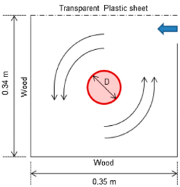
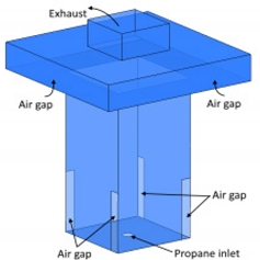
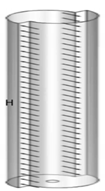
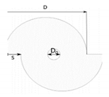
Numerous empirical research works have been published on burner and small-scale pool fire whirls and gaseous fuel fire whirls employing a split cylinder and constant-frame apparatus to analyze the tangential and axial velocity profiles, the radial and axial distribution of temperature, the rates of burning, and the flame heights. The empirical facilities are usually categorized into two types depending on if the circulation is produced by entrained air streams entering the facility tangentially from spiraling gases or is imposed by a mechanically driven rotating screen [69,70,71,72,73,74]. The details of some presented simulation endeavors to-date and the fire whirl behaviour they attempted to capture are expressed in Table 2.
However, significant studies have been conducted to better examine the behavior and mechanisms of fire whirl production in empirical research works. It is hard to obtain outcomes that match the various analyses under the same conditions, as demonstrated by Hayashi et al. [88]. In fact, empirical research on fire whirls is a complex task due to the many limitations of the laboratory. A successful simulation should consider both the quantitative view and the qualitative view of a fire whirl. The qualitative aspects should include some conditions including the transition from a buoyant diffusion gas flame to a stable fire whirl, as well as the stability conditions for the fire whirl.
There is much research that has attempted to estimate the empirical behaviour of fire whirl utilizing various simulation software and methods. The details of some presented simulation endeavors to date and the fire whirl behaviour they attempted to capture are expressed in Table 3.
Based on the results presented in Table 3, in the DNS model, a full range of scales from the smallest to the largest are solved both in time and space. Therefore, the DNS model’s needs are highly computationally demanding; however, in the LES model, only the large scales are solved, and the impacts of the smaller scales are simulated. This is due to the fact that the LES are highly influenced by the boundary conditions and so should be calculated, but smaller scales, which are highly independent of the flow geometry, are isotropic and homogeneous without considering the geometry, and so they can be easily simulated. As a result, the LES model requires lower calculation expenses. The calculation expense related to LES is usually orders of magnitudes greater compared to that for steady RANS computations regarding CPU time and memory. It is known that LES is more reliable and exact compared to RANS for streams in which large-scale unsteadiness appears such as the streams on bluff bodies [33]. Based on the presented results of [71], referenced in Table 3, the Barely Implicit Correction flux-corrected transport algorithm (BIC-FCT) [91], omits the sound velocity limitation by resolving the equations at large time steps specified by the velocity of the fluid (FDS uses the low Mach number formulation), and after that using a pressure correction which efficiently balances the acoustic waves. Specifically, the pressure field is corrected with respect to the energy and momentum equations at each time step. In addition, the flux-corrected transport is applied to estimate the next required time step. Despite the fact that a large number of experiments were conducted on this topic (Table 1), few numerical studies were made. This might be because of the complicated interplays that happen in the generation and the growth of fire whirls [67,68,92,93].

6. Conclusions

Fire whirls produce an intense combustion and have been analyzed by fire researchers due to the hazard they present in wildland and urban fires. Most of the presented data regarding fire whirls has been obtained from simulating tests in the laboratory because the destructive strength of fire whirls covers many properties of their structure. In the present review, empirical arrangements including experimental set up, and applied fuels are presented. In addition, the available simulation methods in numerical studies, including combustion and turbulence models used for the analysis of fire whirls are expanded. This paper demonstrates that more research works should be conducted to find the conditions under which fire whirl is produced, extending the range of factors considered so far and applying other sensors to investigate the temperature and flow field of the flames, presenting information to better investigate, and finding the physical mechanism related to the constitution and complicated dynamics of fire whirls. Based on the presented review, the main findings of the experimental and numerical methods used in fire whirls investigations can be summarized as follows:
  • A successful simulation should consider both quantitative and qualitative aspects of fire whirl. The qualitative approach should include conditions incorporating transition from a buoyant diffusion gas flame to a stable fire whirl, together with stability conditions for the fire whirl.
  • The qualitative features of the models used for numerical analyses should be based on the real physical nature of fire whirls.
  • One of the strengths of the numerical simulation methods is that all ranges of temporal and spatial scales of turbulence in fire whirls are resolved in the computational mesh.
  • While numerical studies will allow for better investigations of the fundamental mechanisms of fire whirl initiation and stability, there are currently not enough studies conducted in this area.

Author Contributions

Conceptualization, M.G., A.S.; methodology, M.G., F.S.; formal analysis, M.G., F.S.; investigation, M.G.; resources, M.G.; writing—original draft preparation, M.G., F.S.; writing—review and editing, A.S.; visualization, D.J.N.; supervision, A.S.; project administration, D.J.N. All authors have read and agreed to the published version of the manuscript.

Funding

This research received no external funding.

Data Availability Statement

Available upon email to corresponding author.

Acknowledgments

This work was supported by computational resources provided by the Australian Government through University of New South Wales under the National Computational Merit Allocation Scheme.

Conflicts of Interest

The authors declare no conflict of interest.

Nomenclature

C p specific heat capacity
C var dynamic stress constant
Kthermal conductivity
NuNusselt number
q heat flux
ReReynolds number
Ttemperature
T g temperature of grid control volume
T f fuel surface temperature
Vdisplacement
x direction
Ycombination fraction
ρ density
ν viscosity
ν t eddy-viscosity
ε d dissipation rate
ε i j the mean strain-rate tensor
δ i j Kronecker’s delta
τ i j the stress tensor of SGS
Δ ¯ grid–filter scale
Δ test–filter scale
χ M dilatation dissipation
γ s o o t soot mass function

References

  1. Yuen, A.C.Y.; Yeoh, G.H.; Cheung, S.C.P.; Chan, Q.N.; Chen, T.B.Y.; Yang, W.; Lu, H. Numerical study of the development and angular speed of a small-scale fire whirl. J. Comput. Sci. 2018, 27, 21–34. [Google Scholar] [CrossRef]
  2. Tohidi, A.; Gollner, M.J.; Xiao, H. Fire Whirls. Annu. Rev. Fluid Mech. 2018, 50, 187–213. [Google Scholar] [CrossRef] [Green Version]
  3. Soma, S.; Saito, K. Reconstruction of fire whirls using scale models. Combust. Flame 1991, 86, 269–284. [Google Scholar] [CrossRef]
  4. Canberra 2003. Australian Disaster Resilience Knowledge Hub. Available online: https://knowledge.aidr.org.au/resources/bushfire-canberra-2003/ (accessed on 3 November 2019).
  5. Moore, T.; Contreras, T.; Murphy, K.; Butler, B.; Forthofer, J.; Bailey, K.; Meyer, R.T.; Richmond, M.; Throop, W.; Petrilli, A.; et al. Indians Fire Accident Prevention Analysis; Forest Service, Department of Agriculture, USFS Pacific Southwest Region: Vallejo, CA, USA, 2008. [Google Scholar]
  6. MacKinnon, E. Fire tornadoes ripped through the Australian outbackvlast week. In Life’s Little Mysteries; Business Insider: Sydney, Australia, 2012. [Google Scholar]
  7. Gao, Z.; Li, S.S.; Gao, Y.; Hung, H.Y.; Chow, W. Numerical studies on swirling of internal fire whirls with experimental justifications. Build. Simul. 2021, 14, 1499–1509. [Google Scholar] [CrossRef]
  8. Emmons, H.W.; Ying, S.J. The fire whirl. In Symposium (International) on Combustion; Elsevier: Amsterdam, The Netherlands, 1967; Volume 11, pp. 475–488. [Google Scholar]
  9. Varaksin, A.Y. Modeling air and fire non-stationary whirls in laboratory conditions. J. Phys. Conf. Ser. 2018, 980, 012019. [Google Scholar] [CrossRef]
  10. Boushaki, T. Introductory Chapter: Swirling Flows and Flames; IntechOpen: London, UK, 2019. [Google Scholar]
  11. Shinohara, M.; Matsushima, S. Flow Visualization Study of Stationary Fire Whirls just Downwind of Meter-Scale Turbulent Flames. Flow Turbul. Combust. 2019, 102, 313–330. [Google Scholar] [CrossRef]
  12. Domino, S.P. The Suitability of Hybrid Meshes for Low-Mach Large-Eddy Simulation (LES); SAND2018-TBD; Computational Thermal and Fluid Mechanics Sandia National Laboratories: Albuquerque, NM, USA, 2018. [Google Scholar]
  13. Wang, P.; Liu, N.; Hart, K.; Smits, A. Measurementof the flow field of fire whirl. Fire Technol. 2016, 52, 263–272. [Google Scholar] [CrossRef]
  14. Hartl, K.A.; Smits, A.J. Scalingof a small scale burner fire whirl. Combust. Flame 2016, 163, 202–208. [Google Scholar] [CrossRef]
  15. Lei, J.; Liu, N.; Zhang, L.; Satoh, K. Temperature, velocity and air entrainment of fire whirl plume: A comprehensive experimental investigation. Combust. Flame 2015, 162, 745–758. [Google Scholar] [CrossRef]
  16. Pirsko, A.R.; Sergius, L.M.; Hickerson, C.W. Causes and Behavior of a Tornadic Fire-Whirlwind; Pacific Southwest Forest & Range Experiment Station: Berkeley, CA, USA, 1965. [Google Scholar]
  17. Forthofer, J.M.; Goodrick, S.L. Review of Vortices in Wildland Fire. J. Combust. 2011, 14. [Google Scholar] [CrossRef]
  18. Tieszen, S.R.; Nicolette, V.F.; Gritzo, L.A.; Moya, J.L.; Holen, J.K.; Murray, D. Vortical Structures in Pool Fires: Observation, Speculation, and Simulation; SAND96-2607; Sandia National Labs: Livermore, CA, USA, 1996. [Google Scholar]
  19. Lei, J.; Liu, N. Reciprocal transitions between buoyant diffusion flame and fire whirl. Combust Flame 2016, 167, 463–471. [Google Scholar] [CrossRef]
  20. Ghodrat, M.; Shakeriaski, F.; Nelson, D.J.; Simeoni, A. Existing improvements in simulation of fire–wind interaction and its effects on structures. Fire 2021, 4, 27. [Google Scholar] [CrossRef]
  21. Chuah, K.H.; Kuwana, K.; Saito, K. Modeling a fire whirl generated over a 5-cm-diameter methanol pool fire. Combust Flame 2009, 156, 828–1833. [Google Scholar] [CrossRef]
  22. Finney, M.A.; Cohen, J.D.; Forthofer, J.M.; McAllister, S.S.; Gollner, M.J.; Gorham, D.J.; Saito, K.; Akafuah, N.K.; Adam, B.A.; English, J.D. Role of buoyant flame dynamics in wildfire spread. Proc. Natl. Acad. Sci. USA 2015, 112, 9833–9838. [Google Scholar] [CrossRef] [PubMed] [Green Version]
  23. Dobashi, R.; Okura, T.; Nagaoka, R.; Hayashi, Y.; Mog, T. Experimental Study on Flame Height and Radiant Heat of Fire Whirls. Fire Technol. 2016, 52, 1069–1080. [Google Scholar] [CrossRef]
  24. Zhou, K.; Liu, N.; Yin, P.; Yuan, X.; Jiang, J. Fire whirl due to interaction between line fire and cross wind. Fire Saf. Sci. 2014, 11, 1420–1429. [Google Scholar] [CrossRef]
  25. Hartl, K.A.; Smits, A.J. Stereo PIV measurements in fire whirls. Exp. Fluids 2019, 60, 17. [Google Scholar] [CrossRef]
  26. Battaglia, F.; Mcgrattan, K.B.; Rehm, R.G.; Baum, H.R. Simulating fire whirls. Combust. Theory Model. 2000, 4, 123–138. [Google Scholar] [CrossRef]
  27. Chuah, K.H.; Kuwana, K.; Saito, K.; Wiliams, F.A. Inclined fire whirls. Proc. Combust. Inst. 2011, 33, 2417–2424. [Google Scholar] [CrossRef]
  28. Lei, J.; Liu, N.; Zhang, L.; Deng, Z.; Akafuah, N.K.; Li, T.; Saito, K.; Satoh, K. Burning rates of liquid fuels in fire whirls. Combust. Flame 2012, 159, 2104–2114. [Google Scholar] [CrossRef]
  29. Hariharan, S.B. Experimental Investigations and Scaling Analyses of Whirling Flames. Ph.D. Thesis, University of Maryland, College Park, MD, USA, 2020. [Google Scholar] [CrossRef]
  30. Taghinia, J.; Rahman, M.M.; Siikonen, T. Large eddy simulation of flow past a circular cylinder with a novel sub grid scale model. Eur. J. Mech. Fluids 2015, 52, 11–18. [Google Scholar] [CrossRef] [Green Version]
  31. Fang, X.; Yuen, A.C.Y.; Yeoh, G.H.; Lee, E.W.M.; Cheung, S.C.P. Capturing the swirling vortex and the impact of ventilation conditions on small-scale fire whirls. Appl. Sci. 2020, 10, 3428. [Google Scholar] [CrossRef]
  32. Taghinia, J.; Rahman, M.M.; Siikonen, T.; Agarwal, R.K. One-equation sub-grid scale model with variable eddy-viscosity coefficient. Comput. Fluids 2015, 107, 155–164. [Google Scholar] [CrossRef]
  33. Parente, R.M.G. Direct numerical simulation and large eddy simulation. In Tackling Turbulent Flows in Engineering; Springer Science & Business Media: Berlin/Heidelberg, Germany, 2011. [Google Scholar]
  34. Moin, P.; Mahesh, K. Direct numerical simulation: A tool in turbulence research. Annu. Rev. Fluid Mech. 1998, 30, 539–578. [Google Scholar] [CrossRef] [Green Version]
  35. Orszag, S.A. Analytical theories of turbulence. J. Fluid Mech. 1970, 41, 363–386. [Google Scholar] [CrossRef]
  36. Heinz, S.; Mokhtarpoor, R.; Stoellinger, M. Theory-based Reynolds-averaged Navier–Stokes equations with large eddy simulation capability for separated turbulent flow simulations. Phys. Fluids 2020, 32, 065102. [Google Scholar] [CrossRef]
  37. Feng, Z.G.; Michaelides, E.E. Heat transfer in particulate flows with direct numerical simulation (DNS). Int. J. Heat Mass Transf. 2009, 52, 777–786. [Google Scholar] [CrossRef]
  38. Piomelli, U. Large-eddy simulation: Achievements and challenges. Prog. Aerosp. Sci. 1999, 35, 335–362. [Google Scholar] [CrossRef]
  39. Mason, P.J. Large-eddy simulation: A critical review of the technique. Q. J. R. Meteorol. 1994, 120, 1–26. [Google Scholar] [CrossRef]
  40. Mahesh, K.; Constantinescu, G.; Moin, P. A numerical method for large-eddy simulation in complex geometries. J. Comput. Phys. 2004, 197, 215–240. [Google Scholar] [CrossRef]
  41. Herring, J.R. Subgrid Scale Modeling—An Introduction and Overview. Turbul. Shear. Flows 1979, 1, 347–352. [Google Scholar]
  42. Canuto, V.M.; Cheng, Y. Determination of the smagorinsky—Lilly constant CS. Phys. Fluids 1997, 9, 1368–1378. [Google Scholar] [CrossRef]
  43. Boussinesq, J. Theorie d l’ecoulelement tourbillant. Mém. Prés. Acad. Sci. 1877, XXIII, 46. [Google Scholar]
  44. Schaefer-Rolffs, U. A generalized formulation of the dynamic Smagorinsky model. Meteorol. Z. 2016, 26, 181–187. [Google Scholar] [CrossRef]
  45. Lilly, D.K. A proposed modification of the Germano subgrid-scale closure model. Phys. Fluids 1992, 4, 633–635. [Google Scholar] [CrossRef]
  46. Nicoud, F.; Ducros, F. Subgrid-scale stress modeling based on the square of the velocity gradient tensor. Flow Turbul. Combust. 1999, 62, 183–200. [Google Scholar] [CrossRef]
  47. Vreman, A.W. An eddy-viscosity subgrid-scale model for turbulent shear flow: Alge-braic theory and applications. Phys. Fluids 2004, 16, 3670–3681. [Google Scholar] [CrossRef]
  48. Tang, H.; Lei, Y.; Li, X.; Fu, Y. Large-eddy simulation of an asymmetric plane diffuser: Comparison of different subgrid scale models. Symmetry 2019, 11, 1337. [Google Scholar] [CrossRef] [Green Version]
  49. Spalding, D.B. Mixing and chemical reaction in steady confined turbulent flames. Symp. Combust. 1971, 13, 649–657. [Google Scholar] [CrossRef]
  50. Magnussen, B.F.; Hjertager, B.H. On mathematical modeling of turbulent combustion with special emphasis on soot formation and combustion. Symp. Combust. 1977, 16, 719–729. [Google Scholar] [CrossRef]
  51. Parente, R.M.; Pereira, J.M.C.; Pereira, J.C.F. On the influence of circulation on fire whirl height. Fire Saf. J. 2019, 106, 146–154. [Google Scholar] [CrossRef]
  52. Su, Y.; Chen, C.; Su, A. Simulation of high temperature air combustion with modi-fied eddy-break-up combustion model. Energy Procedia 2012, 14, 127–132. [Google Scholar] [CrossRef] [Green Version]
  53. Panjwani, B.; Ertesvag, A.; Gruber, A.K.E.R.A.; Rian, K.E. Turbulence combustion clo-sure model based on the Eddy dissipation concept for large eddy simulation. Adv. Fluid Mech. VIII 2010, 69, 27–38. [Google Scholar]
  54. Diab, M.; Yip, A.; Hadavand, M.; Haelssig, J.; Pegg, M. Experimental and numerical comparison of small-scale gaseous fire whirls. J. Phys. Conf. Ser. 2018, 1107, 042032. [Google Scholar] [CrossRef]
  55. Syed, K.J.; Stewart, C.D.; Moss, J.B. Modelling soot formation and thermal radiation in buoyant turbulent diffusion flames. Symp. Combust. 1991, 23, 1533–1541. [Google Scholar] [CrossRef]
  56. Wang, J.; Niioka, T. The effect of radiation reabsorption on NO formation in CH4/air counterflow diffusion flames. Combust Theory Model. 2001, 5, 385. [Google Scholar] [CrossRef]
  57. Liu, F.; Guo, H.; Smallwood, G.J.; El Hafi, M. Effects of gas and soot radiation on soot formation in counterflow ethylene diffusion flames. J. Quant. Spectrosc. Radiat. Transf. 2004, 84, 501–511. [Google Scholar] [CrossRef] [Green Version]
  58. Liu, F.; Guo, H.; Smallwood, G.J.; Gülder, Ö.L. Numerical modelling of soot formation and oxidation in laminar coflow non-smoking and smoking ethylene diffusion flames. Combust. Theory Model. 2003, 7, 301–315. [Google Scholar] [CrossRef] [Green Version]
  59. Shakeriaski, F.; Ghodrat, M. Nonlinear response for a general form of thermoelastici-ty equation in mediums under the effect of temperature-dependent properties and short-pulse heating. J. Therm. Anal. Calorim. 2020, 142, 1–12. [Google Scholar] [CrossRef]
  60. Ajarostaghi, S.M.; Zaboli, M.; Noorbakhsh, M. Numerical evaluation of turbu-lence heat transfer and fluid flow of hybrid nanofluids in a pipe with innovative vortex generator. J. Therm. Anal. Calorim. 2021, 143, 1583–1597. [Google Scholar] [CrossRef]
  61. Shakeriaski, F.; Ghodrat, M.; Escobedo-Diaz, J.; Behnia, M. Modified Green–Lindsay thermoelasticity wave propagation in elastic materials under thermal shocks. J. Comput. Des. Eng. 2020, 8, 36–54. [Google Scholar] [CrossRef]
  62. Zaboli, F.M.; Noorbakhsh, M.; Ajarostaghi, S.S.M. Numerical investigation on heat transfer and fluid flow in a coil tube with lobe cross section and two types of twisted tape as swirl generator. J. Therm. Anal. Calorim. 2020, 141, 1–17. [Google Scholar]
  63. Wrubel, M.H. Exact curves of growth. III. The schuster-schwarzschild model. Astrophys. J. 1949, 119, 51. [Google Scholar] [CrossRef]
  64. Siegel, R.; Howell, J.R. Thermal Radiation Heat Transfer, 4th ed.; Taylor & Francis: New York, NY, USA, 2002. [Google Scholar]
  65. Reddy, B.M. Numerical investigation of soot formation in turbulent diffusion flame with strong turbulence chemistry interaction. J. Therm. Sci. Eng. Appl. 2021, 8, 011001. [Google Scholar] [CrossRef]
  66. AshokeDe, R. Assessment of soot formation models in lifted ethylene/air turbulent diffusion flame. Therm. Sci. Eng. Prog. 2017, 3, 49–61. [Google Scholar]
  67. Holman, J.P. Heat Transfer, 7th ed.; McGraw-Hill: New York, NY, USA, 1990. [Google Scholar]
  68. Consalvi, J.L.; Pizzo, Y.; Porterie, B. Numerical analysis of the heating process in up-ward flame spread over thick PMMA slabs. Fire Saf. J. 2008, 43, 351–362. [Google Scholar] [CrossRef]
  69. Sibulkin, M.; Kim, J. The dependence of flame propagation on surface heat transfer II. Upward burning. Combust. Sci. Technol. 1977, 17, 39–49. [Google Scholar] [CrossRef]
  70. Li, S.; Yao, Q.; Law, C.K. The bottom boundary-layer structure of fire whirls. Proc. Combust. 2019, 37, 4277–4284. [Google Scholar] [CrossRef]
  71. Kuwana, K.; Morishita, S.; Dobashi, R.; Chuah, K.H.; Saito, K. The burning rate’s effect on the flame length of weak fire whirls. Proc. Combust. Inst. 2011, 33, 2425–2432. [Google Scholar] [CrossRef]
  72. Li, S.; Yao, Q.; Law, C.K. An analysis of the stabilization of fire whirls. Proc. Combust. Inst. 2012, 38, 4587–4594. [Google Scholar] [CrossRef]
  73. Zou, G.; Chow, W. Generation of an internal fire whirl in an open roof vertical shaft model with a single corner gap. J. Fire Sci. 2015, 33, 183–201. [Google Scholar] [CrossRef]
  74. Chow, W.K. A study on relationship between burning rate and flame height of internal fire whirls in a vertical shaft model. J. Fire Sci. 2014, 32, 72–83. [Google Scholar] [CrossRef]
  75. Xiaoa, H.; Gollnerb, M.J.; Oran, E.S. From fire whirls to blue whirls and combustion with reduced pollution. Proc. Natl. Acad. Sci. USA 2016, 113, 9457–9462. [Google Scholar] [CrossRef] [PubMed] [Green Version]
  76. Zhou, K.; Liu, N.; Yuan, X. Effect of wind on fire whirl over a line fire. Fire Technol. 2016, 52, 865–875. [Google Scholar] [CrossRef]
  77. Lei, J.; Liu, N.; Tu, R. Flame height of turbulent fire whirls: A model study by concept of turbulence suppression. Proc. Combust. Inst. 2017, 36, 3131–3138. [Google Scholar] [CrossRef]
  78. Wang, P.; Liu, N.; Bai, Y.; Zhang, L.; Satoh, K.; Liu, X. An experimental study on thermal radiation of fire whirl. Int. J. Wildland Fire 2017, 26, 693–705. [Google Scholar] [CrossRef]
  79. Pinto, C.; Viegas, D.; Almeida, M.; Raposo, J. Fire whirls in forest fires: An experimental analysis. Fire Saf. J. 2017, 87, 37–48. [Google Scholar] [CrossRef]
  80. Hariharan, S.B.; Anderson, P.M.; Xiao, H.; Gollner, M.J.; Oran, E.S. The blue whirl: Boundary layer effects, temperature and OH* measurements. Combust. Flame. 2019, 203, 352–361. [Google Scholar] [CrossRef]
  81. Wang, P.; Liu, N.; Liu, X.; Yuan, X. Experimental study on flame wander of fire whirl. Fire Technol. 2018, 54, 1369–1381. [Google Scholar] [CrossRef]
  82. Wang, P.; Liu, X.; Che, L. Experimental study on flame wander of smallscale fire whirl based on video image analysis. In Proceedings of the 2019 9th International Conference on Fire Science and Fire Protection Engineering (ICFSFPE), Dalian, China, 19–21 September 2019. [Google Scholar]
  83. Iga, Y.; Kuwana, K. Generation of Fire Whirls over a Line Fire in a Crossflow: An Ex-perimental Study on the Role of Near-ground Flow. In Proceedings of the 27th ICDERS, Beijing, China, 28 July–2 August 2019. [Google Scholar]
  84. Yamada, R.; Kuwana, K. Scaling laws of flow structures around geometrically similar fire whirls. J. Therm. Sci. Technol. 2019, 14, JTST0009. [Google Scholar] [CrossRef]
  85. Hoo, C.K.; Meng, W.X.; Yi, Y.N.; Wei, C.S. Capturing the fire whirls heights and ro-tational speed by high speed camera. INTI J. 2019, 21, 2600–7920. [Google Scholar]
  86. Varaksin, A.Y.; Mochalov, A.A.; Romash, M.E. Experimental study of some characteristics of nonstationary wall-free fire whirls. High Temp. 2019, 57, 738–743. [Google Scholar] [CrossRef]
  87. Shinohara, M. Effects of wind speed and heat release rate on the vortex strength and size of fire whirls without an inner core of flame. Fire Saf. J. 2021, 120, 103045. [Google Scholar] [CrossRef]
  88. Hayashi, Y.; Kuwana, K.; Dobashi, R. Influence of vortex structure on fire whirl behavior. Fire Saf. Sci. 2011, 10, 671–679. [Google Scholar] [CrossRef]
  89. Hartl, K.; Blackburn, H.M.; Smits, A.J. Experimental and numerical studies of a laboratory fire whirl. In Proceedings of the 19th Australasian Fluid Mechanics Conference, Melbourne, Australia, 8–11 December 2014. [Google Scholar]
  90. Chung, J.D.; Zhang, X.; Kaplan, C.R.; Oran, E.S. Numerical simulation of a fire whirl burning gaseous heptane. In Proceedings of the AIAA Scitech Forum, Orlando, FL, USA, 6–10 January 2020. [Google Scholar]
  91. Zhang, X.; Chung, J.D.; Kaplan, C.R.; Oran, E.S. Simulations of a triple flame and fire whirl using the BIC low-mach-number algorithm. In Proceedings of the 27th ICDERS, Beijing, China, 28 July–2 August 2019. [Google Scholar]
  92. Dermer, P.B.; Varaksin, A.Y.; Leontiev, A.I. The wall-free non-stationary fire whirls generation by ax-isymmetric burning of solid fuel pellets. Int. J. Heat Mass Transf. 2017, 110, 890–897. [Google Scholar] [CrossRef]
  93. Ghaderi, M.; Ghodrat, M.; Sharples, J. LES Simulation of Wind-Driven Wildfire Interaction with Idealized Structures in the Wildland-Urban Interface. Atmosphere 2020, 12, 21. [Google Scholar] [CrossRef]
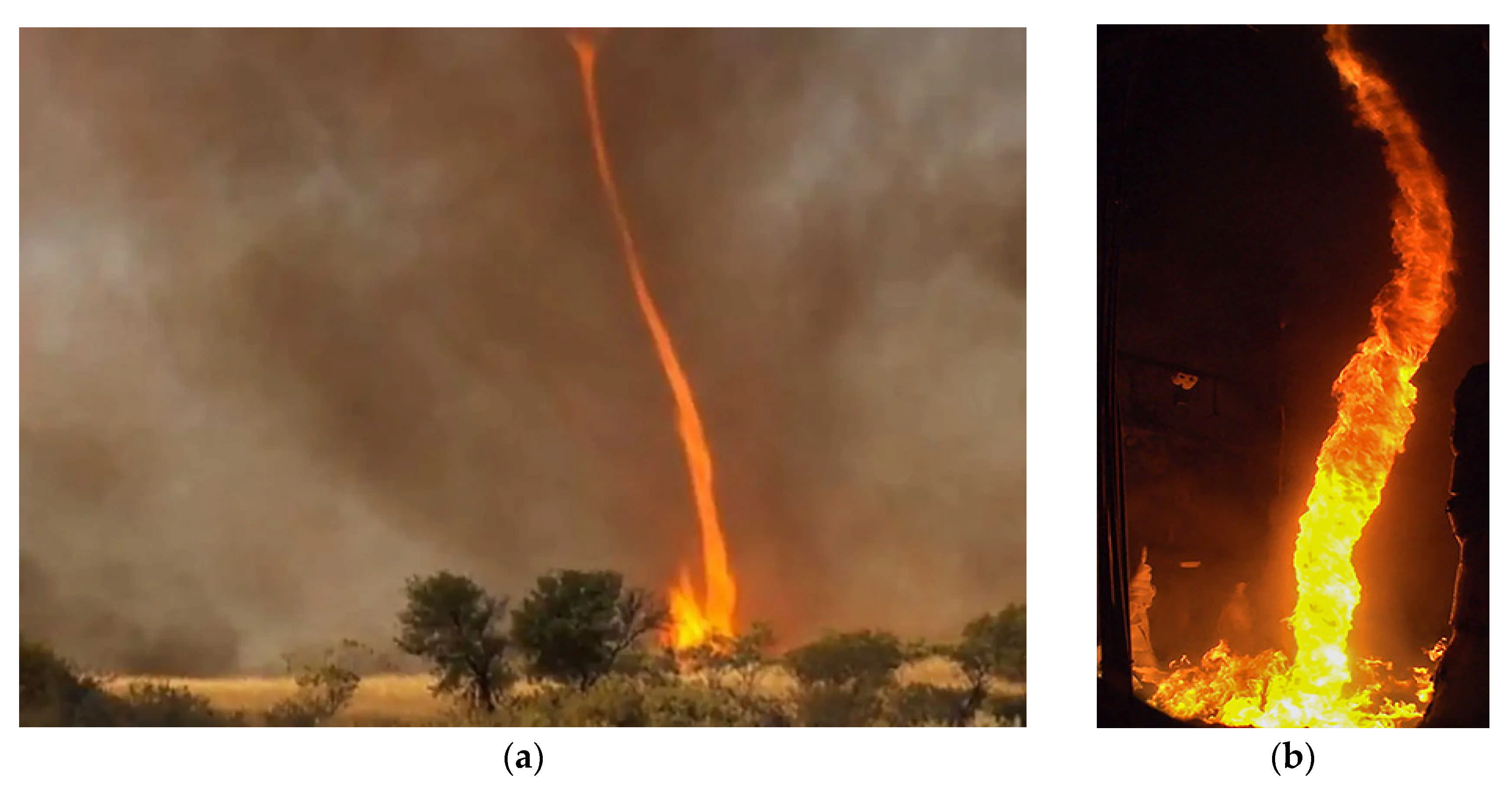
Figure 1. (a): Fire whirls in Australia 2012, photo courtesy of Chris Tangey; (b) Fire whirls from a 3-meter diameter pool in the Fire Laboratory for Accreditation of Modeling by Experiment, or FLAME, facility at Sandia National Laboratories; (c) The process of forming rotating columns of flame; (d) The laboratory fire whirl. Credit: Bryan Christie Design [12].
Fire 04 00043 g001aFire 04 00043 g001b
Figure 2. (a) Schematic of fire whirl formation for an L-shaped heat source in a crossflow wind. View is from above [17]. (b) Schematic showing one configuration that can cause a multiple interacting plume type fire whirl [17].
Fire 04 00043 g002
Figure 3. Fixed frames used in construction of fire whirls. (a) L-shaped covers; (b) cylinder halves.
Fire 04 00043 g003
Figure 5. Instances of pool fire (AC) and fire whirls (panels DF) constituted applying ANS crude oil [29].
Fire 04 00043 g005
Table 1. Displays each SGS model’s formulation for sub-grid scale eddy-viscosity.
Smagorinsky Model (SM) [42] ν S G S = ( C s Δ ¯ ) 2 ε , ε = 2 ε i j ε i j ( 0.5 C s 0.22 ) Δ ¯ is the filter width (size of mesh spacing), ε is the resolved strain-rate tensor
Dynamic Smagorinsky Model (DSM) [44] Based on Lilly’s Idea [45] ν S G S = ( C s Δ ¯ ) 2 ε , ( C s ) 2 = L i j M i j M i j M i j
M i j = 2 Δ ¯ 2 ( ε ˜ ε ˜ i j α 4 η 2 ε ˜ ε ˜ i j )
mostly α = 2, η = 1
The stress Lij can be expressed as the stress related to the smallest solved scales between the grid–filter scale ( Δ ¯ ) and test–filter scale ( Δ ) Δ = ω Δ ¯ .
Wall-Adapting Local Eddy-Viscosity (WALE) Model [46] ν S G S = ( C w Δ ¯ ) 2 ( ε i j d ε i j d ) 3 2 ( ε s i j ε s i j ) 5 2 + ( ε i j d ε i j d ) 5 4 ε i j d = 1 2 ( v g i k v g k j + v g j k v g k i ) 1 3 δ i j ( v g k k ) 2 ε i j s = 1 2 ( v i u j + v j u i ) 0.55 C w 0.6 Here, v g is the tensor of the velocity gradient. Cs and Cw can take different values depending on the nature of the flow, and δ i j is Kronecker Delta function
Vreman Model [47] ν S G S = C V β α ¯ i j α ¯ i j ε α ¯ i j = V j x i β i j = Δ ¯ 2 α m i α m j , ε = 2 ε i j ε i j Δ ¯ is the filter width (size of mesh spacing), and C v = 2.5 C s , Cs can take different values depending on the nature of the flow
Standard One-Equation Model (OM) [48] ν s g s = C ν Δ ¯ ν k s g s , k s g s = ( V i V i ¯ V ¯ i V ¯ i ) / 2 = τ i i / 2 Δ ν = Δ ¯ 1 + C k Δ ¯ 2 ε 2 / k s g s ν s g s is the SGS viscosity, Cv is a constant and always taken to be 0.1, C k = 0.08 , ε , and Δ ¯ are defined in previous models.
Table 2. Experimental studies discussed fire whirls and presenting their considered models.
ReferencesOutcomesFuel TypeSchematic Diagram of Testing Equipment and Tester Equipment Details
(Reproduced from Cited Work)
Dobashi et al. [23]
(2015)
Middle and small-scale tests were conducted to find the mechanism of flame height growth at the fire whirls.n-heptane Fire 04 00043 i001
Fire whirls were constructed on a fuel pool applying a constant-frame-type whirl producer using a pair of L-shaped covers, which produce swirling flow using dragged air.
Xiao et al. [75]
(2016)
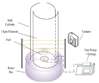
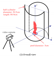
Proposed using the enhanced burning rate of fire whirls for oil spill remediation where the fuel is on a water surface.n-heptane Fire 04 00043 i002
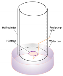
The setup contains two half-cylinders and one cylindrical stainless steel pan filled with water. Fuel is sprayed on the quiescent water surface at the center and ignited. A copper tube under the water is located to pump heptane to the water surface center and keep the fuel height constant.
Lei and Liu [19]
(2016)
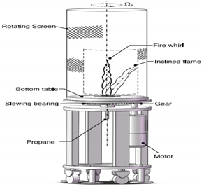
This study examined the reciprocal transition process between fire whirl and a general buoyant propane diffusion flame.Propane Fire 04 00043 i003
A fixed circular table was surrounded by a rotating cylindrical wire-mesh screen. A gas burner was located at the center of the table and accumulated with glass beads. The porous surface was built flat and flush with the burner rim and the surface of the table.
Zhou [76]
(2016)
This study analyzed the fire whirls frequency on a line fire by tests under a significant range of cross wind velocities.Heptane Fire 04 00043 i004
Line fire under the impact of wind was performed using a setup that contains a mechanical wind wall and a line burner placed in a sand bed.
Lei et al. [77]
(2016)
A novel method was proposed to simulate the flame height of turbulent fire whirls by defining a Richardson number related to the average flow quantities.Propane
and
heptane
Fire 04 00043 i005
A square channel setup built of tempered glass was used for turbulent fire whirl tests. The dragged air resulting from the flame entered the channel via four corner gaps and imposed a rotating stream to generate a fire whirl.
Wang et al. [78]
(2017)
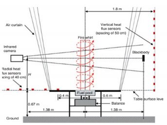
Fire whirl radiation was analyzed in tests performed in a fire whirl facility.n-heptane Fire 04 00043 i006
A system containing four air curtain systems was applied to generate air walls. The facility contains three parts: four air-stream channels, four air curtain mechanisms, and a basis table.
Pinto et al. [79]
(2017)
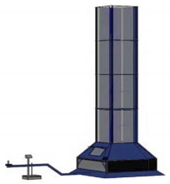
The research work gave an analysis on the structure of fire whirls with and without a forced stream on wildfires at the scale of a laboratory. The outcomes illustrated that forced streams increase the rate of burning.Dead Pinus pinaster, straw of Avena sativa, dead leaves of Eucalyptus globulus. Fire 04 00043 i007
A fire whirl generator including a vertical channel with a quadrangular part with two faces constituted of steel plate and tempered glass was regarded. There was a sheet which was covered by ceramic tiles to protect the fuel enclosure. The generator was located in the great hall of Forest Fire Reseach Laboratory.
Hariharan et al. [80]
(2018)
Analyzed the impact of the surface boundary conditions on the transition process from a fire whirl to a blue whirl.n-heptane Fire 04 00043 i008
The constant-frame setup produces a naturally dragging flow resulting from buoyancy due to the burning fuel in the container. The dish represented smooth surface boundary conditions such as a flat-water surface.
Wang P et al. [81]
(2018)
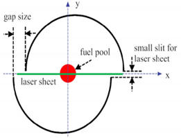
The velocity field was evaluated using stereo Particle Image Velocimetry (PIV) were investigated to track the flame displacement along the horizontal axis.Ethanol Fire 04 00043 i009
Two split cylinders located on a table surface were applied to produce small-scale fire whirls. A round pool was placed at the center of the cylinders. The tiny slit allowed the laser plate to enter the vertical sheet of the fire whirl. The velocity distribution was measured using stereo PIV.
Wang et al. [82]
(2019)
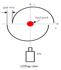
A video camera was used to monitor the fire whirl horizontal movement due to the wandering of the flame.Ethanol Fire 04 00043 i010 Fire 04 00043 i011
Stages: (1) transmitting the flame image to the related binary image; (2) deriving the flame contours and specifying the flame, center; (3) computing the horizontal distance from the center of the flame to the center of the fuel pool.
Iga and Kuwana [83]
(2019)
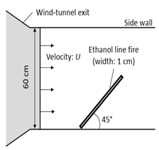
This study analyzed the impact of near-ground flow on the frequency of fire whirl constitution.Ethanol Fire 04 00043 i012
A wind tunnel was applied to produce a cross stream of velocity U, and a blocking board was located to cover the wind-tunnel exit and control its opening height (h).
Yamada and Kuwana [84]
(2019)
This study analyzed the scale impacts on the flow structure in fire whirl with emphasis on if a dynamic similarity stays satisfied among geometrically analogous fire whirls.Methanol Fire 04 00043 i013
Two half-cut cylinders with asymmetrically located slits were used to provide a rotating stream by entrainment due to upward, buoyant flow from a fire resource.
Hoo et al. [85]
(2019)
This study analyzed the rotational velocities and the fluctuation frequencies of fire whirl.Ethanol Fire 04 00043 i014
The generator of the fire whirl was a constant-frame-type including two semi-cylindrical walls located near the fuel pan, and the center of the walls of the curvature are offset by a tiny distance from the fuel pan’s center to constitute two air gaps between the walls.
Varaksin et al. [86]
(2019)
This study presented outcomes about the procedure of non-static, wall-free fire whirl production.Urotropine Fire 04 00043 i015
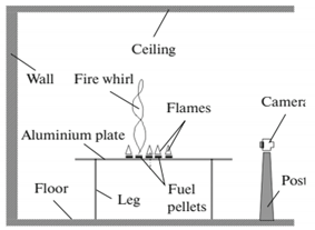
A setup is used to produce non-static, wall-free concentrated fire whirls. The table’s horizontal surface was made of an aluminum sheet with a thickness of 1.5 mm and a diameter of 1100 mm.
Shinohara [87]
(2020)
This study investigated the impact of crosswind velocity and thermal release rate on the size, speed, and circulation of fire whirl.Methane Fire 04 00043 i016
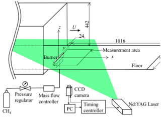
Tests were done in an open blowdown wind tunnel. The experiment section consisted of a flat floor, heat-resistant glass. The burner exit was a porous rectangular sheet built of sintered stainless-steel particles.
Table 3. Recent numerical analyzed fire whirls and presenting their simulations.
ReferencesOutcomesNumerical Method/SoftwareFuel TypeTurbulence ModelCombustion ModelSchematic Diagram of Numerical Method
Hartl et al. [89]
(2014)
Demonstrated the feasibility of applying DNS for modeling swirling buoyant turbulent plumes.Spectral element–Fourier
method
dimethyl
ether
DNSNone, heat input using flux
boundary conditions
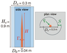
Fire 04 00043 i017
Yuen et al. [1]
(2018)
Showed that liquid fuel simulations can estimate the rate of evaporation.Finite difference methodEthanolLES
(Smagorinsky model)
Mixture fraction simulation (Gas-phase combustion model) Fire 04 00043 i018
Diab et al. [54]
(2018)
Investigated the dynamics of propane gas fire whirls in a small-scale, constant-frame, square-based system.Finite volume (ANSYS Fluent 17.1)PropaneLES
(four different SGS models, including Deardorf, WALE)
Mixture fraction simulation (based on the EDC (Eddy Dissipation Concept) Fire 04 00043 i019
Parente et al. [51]
(2019)
Studied the ability of the RST to measure physical behaviour of fire whirls (for example, the effects of used swirl generator on the flame height).Star-CCM+ softwarePropaneRSTEddy Break-Up Fire 04 00043 i020 Fire 04 00043 i021
Fang et al. [31]
(2020)
Illustrated the capability of the generic LES model in capturing the dynamic response of fire whirl.ANSYS
Fluent
PropaneLES (Smagorinsky–Lilly model)Combination fraction Fire 04 00043 i022
Chung et al. [90]
(2020)
Illustrated that the blue whirl is made of various flame regimes: lean, premixed rich, and a diffusion flame.The algorithm of Barely implicit correction (BIC)Ethanol and heptane---Superimposed thermal release rate Fire 04 00043 i023
Publisher’s Note: MDPI stays neutral with regard to jurisdictional claims in published maps and institutional affiliations.