Article

The Effect of Electrode Geometry on Excited Species Production in Atmospheric Pressure Air–Hydrogen Streamer Discharge

by
Shirshak Kumar Dhali
* and
Stuart Reyes
Department of Electrical and Computer Engineering, Old Dominion University, Norfolk, VA 23529, USA
*
Author to whom correspondence should be addressed.
Plasma 2025, 8(4), 42; https://doi.org/10.3390/plasma8040042
Submission received: 25 August 2025 / Revised: 8 October 2025 / Accepted: 14 October 2025 / Published: 15 October 2025
(This article belongs to the Special Issue Processes in Atmospheric-Pressure Plasmas—2nd Edition)

Abstract

When a gas is overvolted at or near atmospheric pressure, it results in a streamer discharge formation. Electrode geometries exert significant impact on the electrical breakdown of gases by altering the spatial profile of the electric field. In many applications the efficient generation of radicals is critical and is determined by the characteristics of the streamer discharge. We examine the effect of electrode geometry on the streamer characteristics and the production of radicals. This is performed for three different electrode geometries: plane–plane, pin–plane, and pin–pin. A two-dimensional rotationally symmetric fluid model is used for the streamer discharge simulation in the hydrogen/air gas mixture. The spatial profile of electron density and the electric field for point electrodes show significant differences when compared to plane electrodes. However, the efficiency of radical generation shows similar trends for the electrode configurations studied. We also present the results of spatial electrical energy density distribution which in turn determines spatial excited species distribution. These results can inform the design of specific applications.

1. Introduction

The excited species in a non-thermal plasma provides a highly reactive environment at or near room temperature. The plasma chemical reactions form the basis for many mature and emerging technologies [1,2,3,4,5,6]. There are many methods to create a non-thermal plasma at atmospheric pressure by the electrical breakdown of gases, including high voltage repetitive pulses, radio frequency (RF) discharges, and DC discharges [2,7,8,9]. Some of the methods such as RF and DC are better suited for pressures lower than atmospheric pressure [2]. At atmospheric or higher pressures, most discharges tend to form arcs as they reach a steady state [10,11,12]. However, if the electrical discharge is terminated during the transient phase, low temperature non-thermal plasmas can be obtained. In a dielectric-barrier discharge (DBD), the electric field decreases in the gap due to the charging of the dielectric leading to the extinction of the micro-discharges. In repetitive nanosecond pulsed discharges, the pulse width is adjusted to avoid arc formation. During the transient phase the discharge starts as an avalanche, and as the space charge starts to dominate the electric field it turns into a streamer [13,14,15,16,17,18]. The transient phase of the electrical breakdown at atmospheric pressure is responsible for the creation of excited species which are the precursors for the plasma chemical conversion in most applications [19].
Commonly used electrode geometries for creating a DC or pulsed electrical discharge include plane–plane, point–plane, and point–point. The electrode geometry determines the spatial electric field, which in turn influences the temporal evolution of the electrical discharge. A large volume of work on streamers is available for the plane–plane geometry [13,14,15,16,20,21]. In our previous work, we investigated the fluid models appropriate for streamer simulations, and radical production efficiency for plane–plane electrodes [22,23]. Point–plane electrode configuration is frequently used in atmospheric pressure plasma, particularly with a liquid surface acting as a plane electrode [24,25,26,27,28,29]. Yamazawa and Yamashita have performed detailed calculation of the electric field for point–plane gaps using the finite element method [25]. Bourdon et al. have reported on the influence of the electrode set-up geometry on the characteristics of ionization fronts [26]. They found that the radius of curvature of the tip of the point electrode and its exact shape have a negligible effect on the discharge properties. They also observed that the propagation speed of the discharge front is high close to the tip of the anode point and decreases further away from the tip. Sato et al. have reported on the effects of voltage polarity for a pin-to-plane electrode geometry in atmospheric pressure argon [27]. They concluded that low-voltage operations with positive polarity applied to the pin electrode were useful for obtaining stable high electron density plasma for atmospheric pressure argon. Fu et al. investigated the scaling laws of various electrode configurations [28]. They concluded that gap geometry, which results in local field enhancements, is of critical importance on the breakdown characteristics.
In this paper, we report the results of streamer formation and propagation in three different electrode geometries: plane–plane, pin–plane and pin–pin. This was performed for atmospheric pressure air–hydrogen fuel mixture. This particular gas composition was chosen as an application of plasma in the control of combustion [30,31,32,33,34]. The combustion kinetics of this gas mixture is well understood, and the efficient radical production is important for the control of the combustion characteristics [7,31,35,36,37,38,39,40]. In this study, a first order drift-diffusion fluid model for the streamers is used in two dimensions with rotational symmetry [11]. Our emphasis in this article is to understand the effect of electrode geometry on excited species production. We also look at the spatial extent of the energy density in a streamer, since energy density is the determining factor of radical density.

2. Streamer Model and Numerical Method

During the transient phase of the electrical breakdown of gases, which is in the ns timescale, the heavy particles do not gain energy, and the neutral gas and ion are at or near room temperature. Due to heavier mass, the ion mobility is orders of magnitude lower than electrons’, so the ions can be considered stationary compared to the lighter electrons and the convective terms in the conservation equations for the ions can be ignored. In the space-charge-dominated streamer type, discharge the ionization front propagates at speeds several times higher than the local electron drift velocity and the plasma density forms steep spatial gradients due to the rapid growth of ionization. The approach to the modeling of streamers can be broadly characterized as fluid or kinetic [41,42,43]. The kinetic models solve the Boltzmann equation along with the Poisson equation to determine the phase space of particles, and are computationally expensive. A hybrid approach of particle-in-cell Monte Carlo simulation along with a lumped solution of Poisson’s equation has been successfully used for modeling stochastic fluctuations [20]. The first three moments of Boltzmann’s equation give the particle, momentum, and energy conservation equation used for fluid models. In the second order fluid model, the energy equation is solved for local electron mean energy. The transport properties and rates in a second order model are parameterized using the local mean energy approximation (LMEA). The first order drift-diffusion fluid model is based on local field (E/N) approximation (LFA). In an earlier publication, we have reported on the parametrization of fluid models, and found that at atmospheric pressure, in molecular gases, the first order model works as well as the LMEA [22,43]. In this study, the LFA model for an attaching gas is used for solving the following particle conservation equations [12,13,14,44,45,46,47]:
n e t = . Γ e E / N + n e ν I E / N n e ν a E / N + S
n i t = n e ν I E / N + S
n n t = n e ν a E / N
where n e   n i , and n n are the electron, positive ion, and negative ion densities, respectively, ν I is the ionization frequency, and ν a is the attachment frequency. For non-attaching gases Equation (3) can be ignored as ν a = 0. The quantity S represents various ion/electron source or sink mechanisms, such as photoionization, recombination, or remnant space charge in repetitive discharges. Assuming isothermal plasma and ideal gas law, the particle flux can be obtained from the momentum conservation equation and is given by the following [14,34]:
Γ e E / N = n e μ e ( E / N ) E D e ( E / N ) n e
where μ e is the electron mobility, De is electron diffusion coefficient, and E is the electric field vector.
The spatial distribution of the electric field E can be obtained from the solution of the Poisson equation [3,14,34].
2 Φ = q e ( n i n e n n ) / ϵ o E = Φ
where Φ is the electric potential, qe is the elementary charge, and ϵ o is the free space permittivity. The energy (eV) deposited in the gap during a time interval t can be found from the following:
t = t | E | 2   n e μ e d 3 r .
The density of the generic radical produced by the electron impact excitation process is shown in Equation (7) where the excitation frequency, ν k E / N , is spatially and temporally dependent on the local field, E/N. At each time step, Equation (7) is used to calculate the generation of the excited species “k” from the spatial electron density distribution and the excitation frequency, which is a function of local field [19].
d N k t = t   n e r , z , t ν k E / N d 3 r
The electrode geometries investigated consist of plane–plane, pin–plane and pin–pin configurations. The set of Equations (1)–(5) was solved numerically using a two-dimensional finite difference method assuming rotational symmetry. The flux-corrected transport (FCT) method proposed by Boris and Book was used for the convective term of electron density [48,49]. This method is particularly suitable for handling the steep density gradients and strong field changes encountered in streamer propagation. An eight-order scheme was used to find the high-order flux, and the donor cell for the low-order scheme. The details of the method as applied to streamers have been extensively reported [13,14,15,16]. Poisson’s equation is solved for the electric potential by successive over-relaxation (SOR) method [50]. This iterative method converges rapidly as the perturbation in charge density is small compared to the previous time step. For gap distance d, a suitably chosen large radial distance R, and an applied voltage V, the boundary conditions on Φ ( r , z ) in the cylindrical domain 0 ≤ z ≤d and 0 ≤ r ≤R are Φ r , s 1 = V , Φ r , s 2 = 0 , Φ r r = 0 = 0 , and Φ R , z = V d . The surface contours of the two parallel plate electrodes are represented by s1, and s2.

3. Results and Discussions

In order to compare the results of the three different electrode configurations, we kept the shortest distance between the two electrodes the same for all three cases: the plane-to-plane electrode separation was 3.5 mm, the pin-tip-to-plane separation was 3.5 mm, and the pin tip to the other pin tip was 3.5 mm. All the results presented here are for an applied voltage of 15 kV for the three different electrode configurations. The pin electrode comprised a cylinder 1 mm in diameter and 0.75 mm in height with a semi hemispherical top of 1 mm diameter. Similar electrode configurations have been reported by other investigators [24]. A non-uniform mesh both in the z and r directions was used with a finer mesh near the electrode tip. The smallest mesh size was 5 μm. There was a wide parameter range over which the simulations could be performed. Bourdon et al. reported numerical studies of the effect of electrode set-up geometry on the morphology of the ionization wave at atmospheric pressure air [26]. They concluded that the radius of curvature of the electrode tip (100–1000 μm) and the shape of the electrode (rod or hyperbola) had negligible influence on streamer properties. Although a parametric study would be useful, the simulations presented here were performed for only one geometry for each of the three electrode configurations. Therefore, it is difficult to draw general quantitative conclusions. However, our goal is to achieve a qualitative understanding of the electrode geometry effect on streamer properties and radical production.
The transition from avalanche to steamer discharge requires the buildup space charge. Therefore, for the streamer simulations, we bypassed the avalanche phase by placing a neutral plasma on either electrode. Once the streamer develops, the properties of the streamer propagation do not depend on this initial charge [13,14]. A Gaussian-shaped neutral plasma was placed on one of the electrodes. The shape of the initial distribution along the radial and axile direction is given as ne(z, r) = 1018exp(−((zzo)2/0.001)exp(−r2/0.001)/m3 where zo is the tip position for pin electrodes. In the case of the pin–pin electrodes, initial plasma was placed on both tips. This configuration produced a streamer discharge whose properties are characterized in this study. Due to numerical instabilities, the simulations were stopped when the streamer bridged the gap. The “S” term in Equations (1) and (2) represents the source of free electrons. In air, the mechanism of photoionization is attributed to the 98–102.5 nm emission from excited nitrogen molecules by electron impact which can ionize an oxygen molecule [21]. The determination of photoionization requires the cross-section data, which is not readily available for gas mixtures. The most commonly used cross-section data is a 1970 article by Penny and Hummert where they report the photoionization measurements in air, oxygen and nitrogen [51]. There are several reports on the use of Penny and Hummert data for the study of streamers in air and nitrogen. These studies concentrated on detailed aspects of streamers, such as branching [52,53]. Wei et al. studied streamer discharge in humid air [54]. They concluded that the photoionization rate is about three orders of magnitude lower than electron impact ionization. Therefore, photoionization had negligible influence in the propagation of streamers. In this work, to overcome this problem, the photoionization term “S” in Equations (1) and (2) was simulated by a very low-density spatially uniform neutral plasma. A constant background charge of 1011/m3 was added to simulate the photoionization. These assumptions have been widely studied and their impact on the generation and propagation of streamers is not critical for the study of radical generation for different applications [13,14,16].
The results presented here are for air–hydrogen mixture for an equivalence ratio of ϕ = 1 (N2 58%, O2 14%, H2 28%), which is the ratio between the oxygen and hydrogen in the gas that is required for complete stoichiometric combustion. Since a first order fluid model is being used, the electron mobility, the diffusion constant and the rate constants of electron impact processes are obtained as a function of the reduced electric field (E/N) from an open-source Boltzmann equation solver, BOLSIG+, for the gas composition of interest [55]. The electron impact cross-sections for the gas mixture (N2, O2, and H2) under study are available at lxcat.net, which is the most up-to-date database [56].
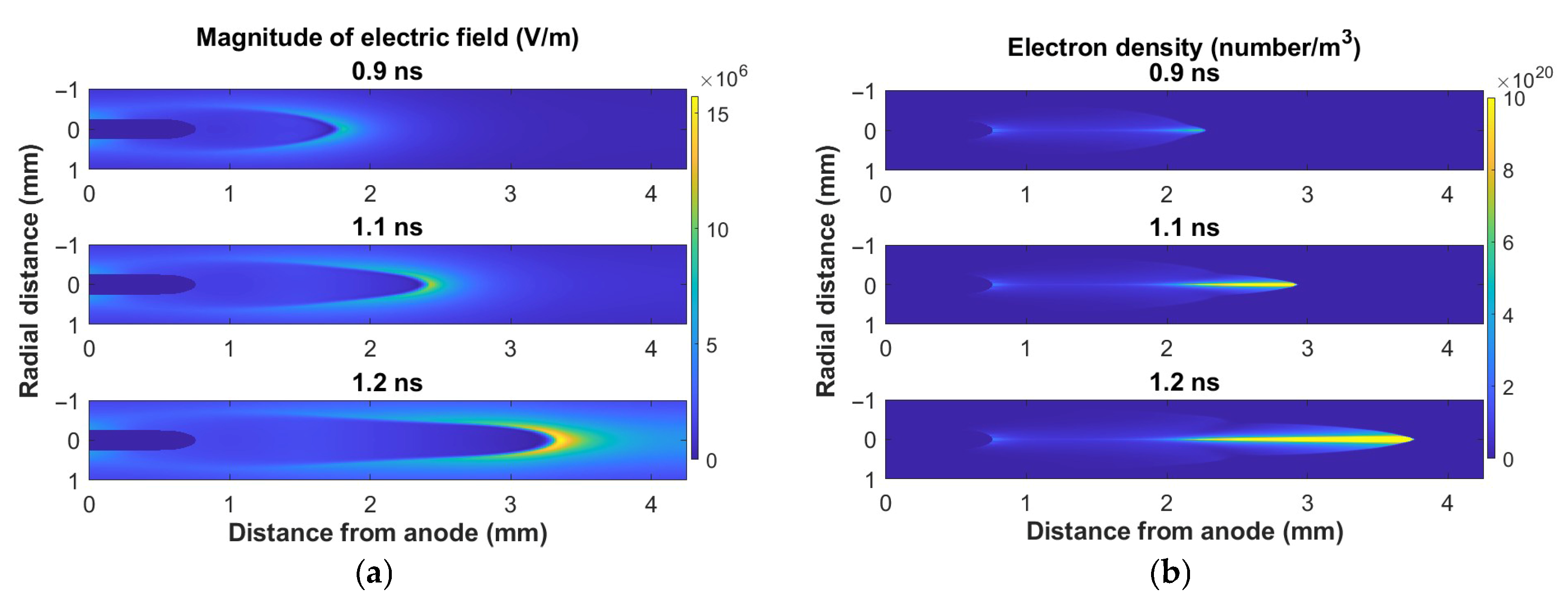
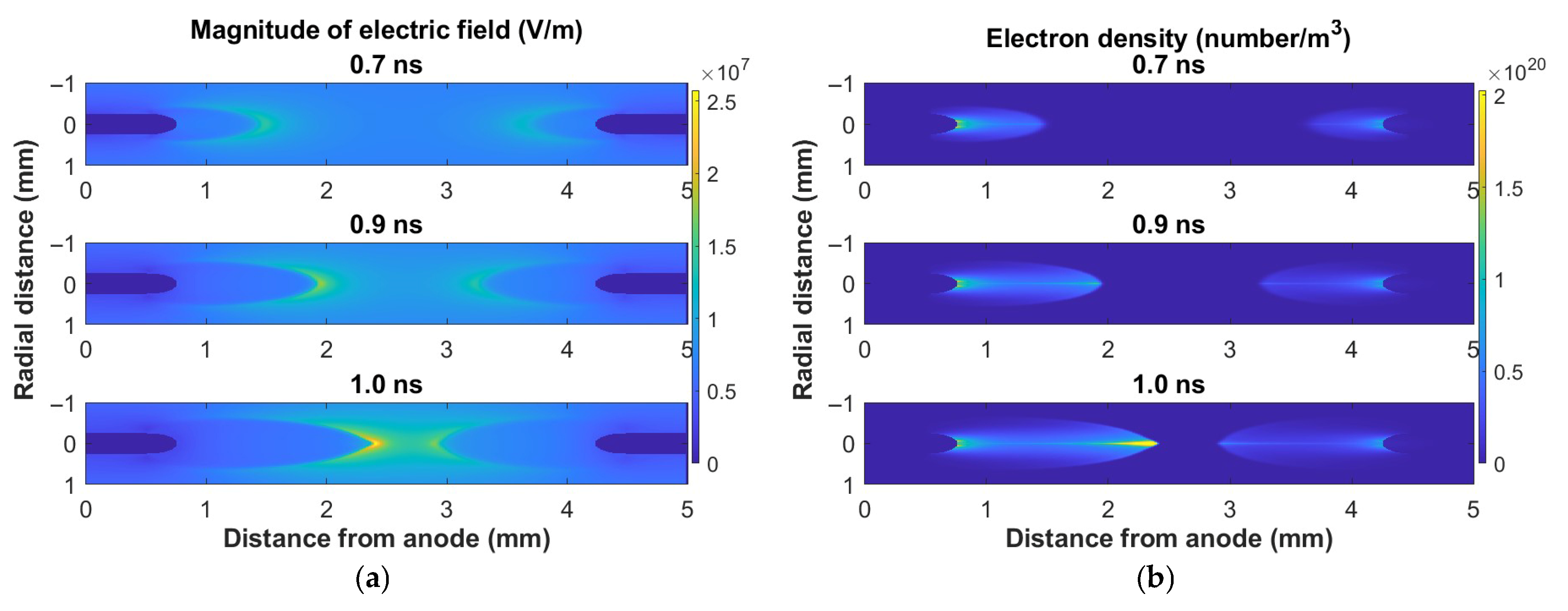
Figure 1, Figure 2 and Figure 3 show the images of the magnitude of the electric field and electron density for the three different electrode configurations. The initial charge was placed on the anode for plane–plane and pin–plane electrodes. This produces a cathode-directed streamer with electron drift which is opposite to the propagation of the ionization front. In the pin–pin electrodes, since an initial charge was placed on both the electrodes, a cathode-directed and an anode-directed streamer were formed. In the pin–pin electrode, the cathode-directed steamer had higher field enhancement and the front had higher density compared to the anode-directed streamer. This has been shown to be the case for plane–plane electrodes in previously reported results [11,14]. The images for point electrodes show radial profiles that are sharper at the tip. The radial extent of the streamer in the plane-to-plane electrodes is larger than either the pin–plane or pin–pin electrodes. The electron density in the pin electrodes is high along the axis and the tip. This can be attributed to the uniformly applied field for the plane-to-plane geometry, whereas the applied field for a point electrode radially decreases further away from the axis [23].
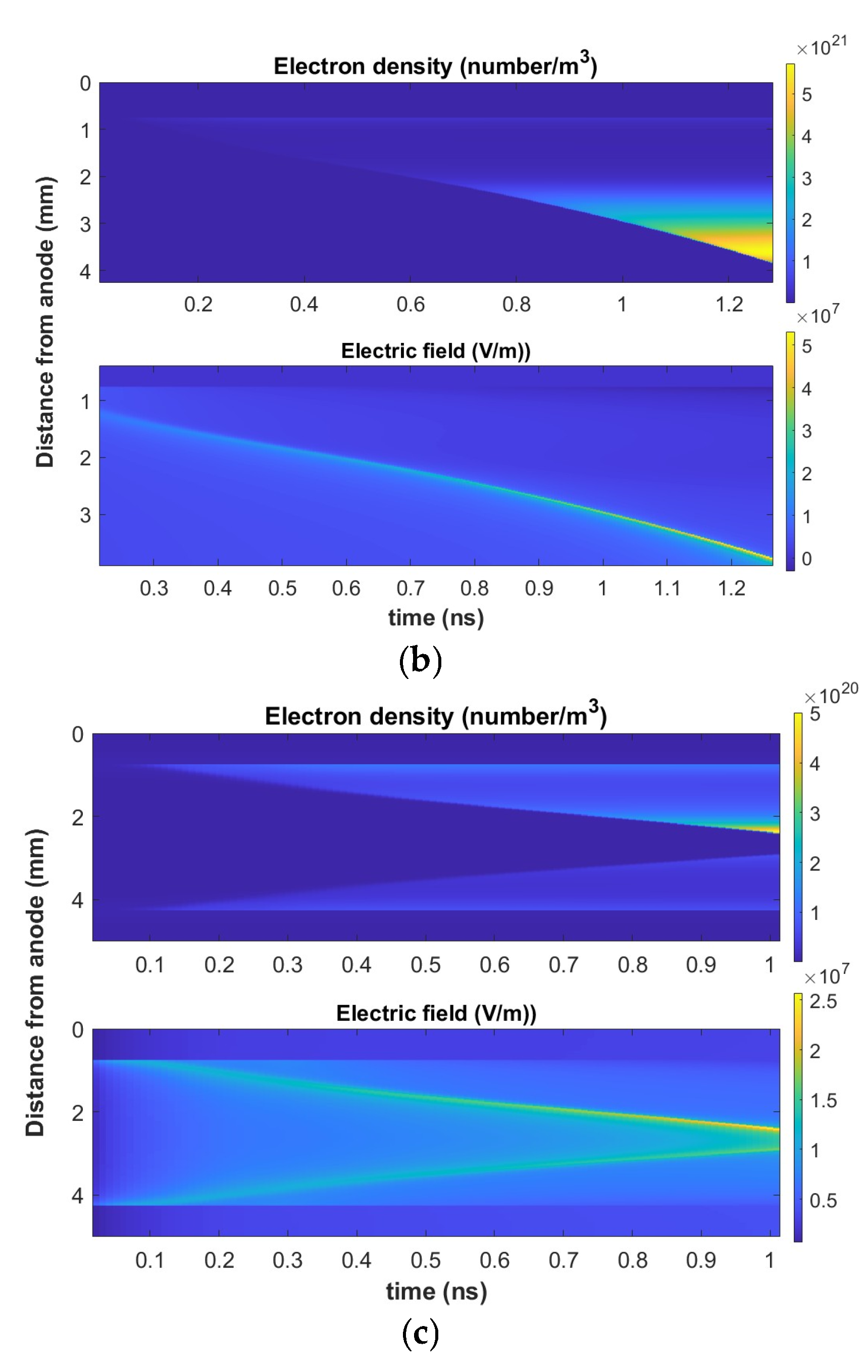
The sharp changes in the electron density and the electric field at the streamer front is best illustrated by the streak images of the axial electron density and the axial electric field shown in Figure 4. In the images, the color bars have different scales as the densities and field have different orders of magnitude for the three electrode geometries. The streamer formation and speed are higher for the pin electrodes compared to the plane electrodes. The axial electric field ahead of the streamer front in the streak image for the plane-to-plane electrode shows a slower decay compared to the other electrodes.
In Figure 5, the electric field and the electron density along the axis are shown for the three electrode configurations. These plots are for an instant in time of the streak images. For comparison, these snapshots were at time instances when the streamer reached approximately the halfway distance in the gap. In all cases, there is a steep gradient of both the electron density and the electric field at the ionization front. However, the drop of the electric field outside the streamer body in the plane–plane electrode is slower compared to the other two, which can also be observed in the streak images. This is also evident in the image of electric field, shown in Figure 1, where the field forms a wider band around the streamer front. This is due to the decrease in the applied field away from the tip of the pin electrodes.
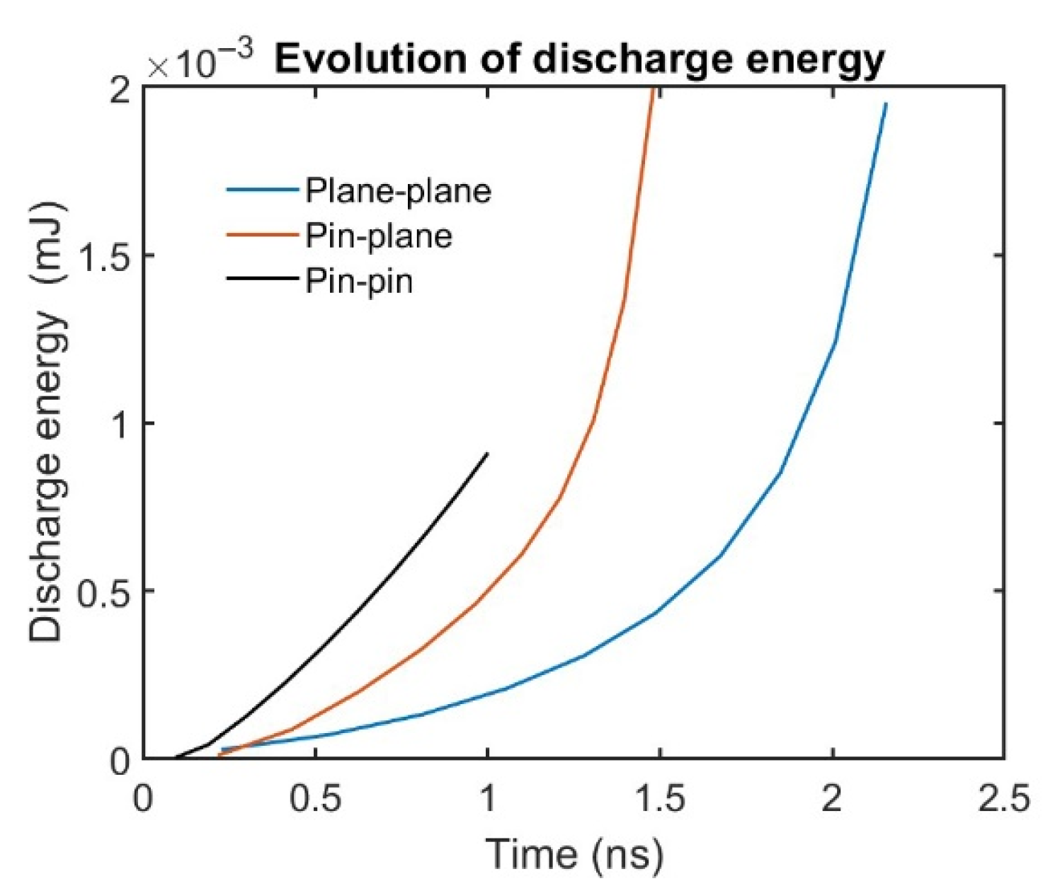
The plots in Figure 6 show the total energy deposited in the gas as a function of time. These plots are for the duration it takes the streamers to bridge the gap for the three electrode geometries which are different. The pin–pin is simulated for the duration when the cathode- and anode-directed streamers meet close to the middle distance of the gap. Due to the field enhancement at the tip of both the pin–plane and the pin–pin electrodes, a larger amount of electrical energy is coupled with the discharge in the early phase of the streamer development in comparison to the plane–plane discharge. However, with time, the plane–plane electrode develops a larger volume (see Figure 1), and this results in greater coupling of electrical energy.
For combustion applications, the production of dissociated oxygen and hydrogen is important in determining ignition delays. These radicals are generated by electron collision excitation to repulsive electron states. The important products include oxygen and hydrogen atoms. A subset of the reactions leading directly to these products are listed below [57,58].
e + O 2 6.0   e V O 2 ( A 3 Σ u + ) + e O ( 3 P ) + O ( 3 P ) + e
e + O 2 8.4   e V O 2 ( B 3 Σ u ) + e O ( 3 P ) + O ( 1 D ) + e
e + H 2 8.9   e V H 2 b 3 Σ u + + e H ( 1 S ) + H ( 1 S ) + e
e + H 2 11.8   e V H 2 ( B 1 Σ u + ) + e H ( 1 S ) + H ( 1 S ) + e
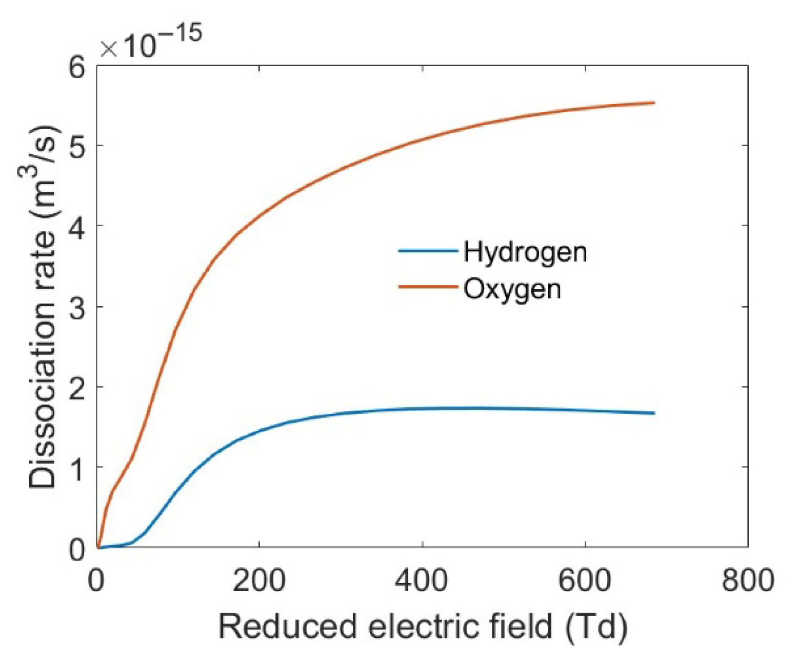
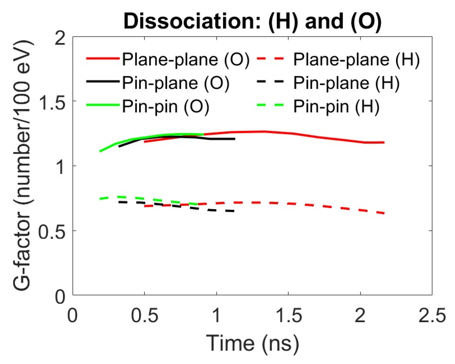
For efficiency comparison, a measure that is often used where radical production is critical for the application is the G-factor, which is defined as the number of excited species produced by electron impact for every 100 eV input of electrical energy [3]. The electron impact rates (Equations (8)–(11)) are obtained from the solution of Boltzmann equation with BOSLIG+. Figure 7 shows the total dissociation rates for the oxygen and hydrogen molecules as functions of the reduced electric field, which are used to determine the densities. During the simulation, Equation (6) is used to determine the electrical energy deposited over the entire volume in a time interval Δt. A time integral is performed to determine the cumulative energy at an instant in time. Similarly, Equation (7) is used to determine the radical concentration over the entire volume for a time interval Δt. The cumulative density at any instant in time is obtained by time integration. We assume there is no convective loss or gain of energy in the ns time scale. The ratio of the radical density to the energy input gives the G-factor at that instant in time. Figure 8 shows the G-factors for oxygen and hydrogen atom production for different electrode geometries as a function of time. Since the threshold energy for the electron impact processes leading to hydrogen dissociation are higher than oxygen dissociation, the G-factor will be lower than the G-factor for oxygen atom production. The trends for hydrogen atom and oxygen atom production are very similar for all three electrodes. Since the streamer formation from the initial charge distribution takes about 0.2 ns, the plots are shown to start at that time. The G-factor of the important dissociation products for combustion is almost constant during the streamer propagation. This observation was noted in one of our earlier publications [23]. Although the reduced electric field at the streamer front increases with time (Figure 1, Figure 2 and Figure 3) for all three electrode geometries, the rates for most electron impact processes start to flatten at such high fields (see Figure 7). This reduces the impact of radical production due to high field enhancement. Also, the bulk of the electrons are under a low electric field due to shielding which favors low-threshold energy processes such as vibrational excitation. The electrode geometry does not influence the energy partitioning, and the species’ density primarily depends on the energy deposited in the volume of the gas. Therefore, the G-factor can be defined as a macroscopic property of the streamer which, once evaluated, can be used to determine the radical density from the electrical energy density of the discharge for chemical conversion simulations for different electrode arrangements.
From an application viewpoint, besides the G-factors of specific species, the spatial distribution may also be relevant. In this context, the spatial distribution of the electrical energy in the streamer would be useful. There are no reported results in the literature on the spatial energy distribution in a streamer discharge. Figure 9 shows the spatial energy distribution for the three electrode arrangements. The instantaneous power (eV/(m3s)) deposited at a special location is determined from | E | 2   n e μ e where |E| and ne are space dependent. This quantity is integrated over time, assuming no convective gain or loss of energy in the time scale of ns. The time instances shown in Figure 9 are the same as in Figure 5, when the streamer reaches approximately the midpoint of the gap length. The plane–plane electrode system shows a wider radial spread of the energy deposition because of the uniformity of the applied field. For the pin electrode geometries, the higher energy deposition is along the axis and the pin electrode tip. Since the applied field is highest near the tip of the pin electrode, the energy deposition would also be high there.
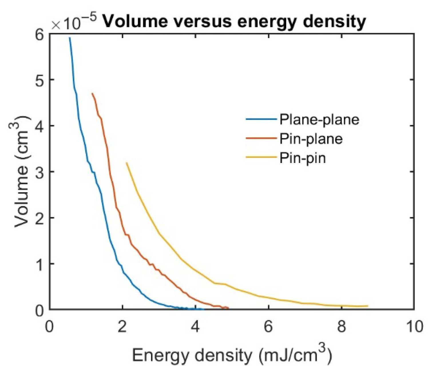
In applications such as plasma-assisted combustion, the ignition kernel development will not only depend on the energy density but also the volume. From the spatial energy distribution at any given time, the volume associated with energy density can be estimated. This can be performed by discretizing the energy density and adding the volumes associated with it. Figure 10 shows the plot of the volume associated with energy density for the three electrode geometries. These plots were generated from Figure 9 by discretizing the energy density and counting the volume associated with each energy density bin. The bulk of the energy density is below 3 mJ/cm3 for all the electrodes. This can also be seen in the images of the energy density in Figure 9, where the bulk of the streamer is in the energy density range from 2 to 4 mJ/cm3. The point-to-point geometry due to the high field region near the point electrode shows larger volumes with higher energy density. Although these results are for a very limited range of parameters, they give a qualitative understanding of the influence of electrode geometry. For design purposes, a more detailed analysis would be required to establish a quantitative assessment of the volume associated with energy density for different applied voltages and the pulse width of the applied voltage.

4. Conclusions

At atmospheric pressure, the transient phase of the discharge is modeled as a steamer. The electrode geometry determines the spatial electric field which in turn influences the temporal evolution of the electrical discharge. For a plane–plane geometry the applied field is spatially uniform, whereas for pin electrodes it is highest at the tip. The streamer propagation in a plane–plane geometry has a wider radial profile compared to the pin electrodes. The excited species production efficiency, G-factors, is very similar in the three electrode geometries investigated. Similarly to that reported in an earlier publication for plane–plane geometry, the G-factors remain fairly constant once the streamer is developed for all three electrode types [23]. From a design perspective, for an application, the electrical energy coupling with the discharge can be used to obtain a good estimate of the excited species concentration. The other important factor is the spatial distribution of the energy. From the simulations, the volume associated with energy density was obtained. The pin geometries show regions with higher densities compared to plane geometries.

Author Contributions

Conceptualization, S.K.D.; Software, S.R.; Validation, S.R.; Formal analysis, S.K.D.; Resources, S.K.D.; Data curation, S.R.; Writing—original draft, S.K.D.; Project administration, S.K.D.; Funding acquisition, S.K.D. All authors have read and agreed to the published version of the manuscript.

Funding

This research was funded by the US Office of Naval Research (Grant Number: W911NF-23-1-0173) and the National Science Foundation (Award Number: 2337461).

Institutional Review Board Statement

Not applicable.

Informed Consent Statement

Not applicable.

Data Availability Statement

The original contributions presented in this study are included in the article. Further inquiries can be directed to the corresponding author.

Acknowledgments

This work was partially supported by the US Office of Naval Research and the National Science Foundation.

Conflicts of Interest

The authors declare no conflicts of interest.

References

  1. Kogelschatz, U. Dielectric-Barrier Discharges: Their History, Discharge Physics and Industrial Applications. Plasma Chem. Plasma Process. 2003, 23, 1–46. [Google Scholar] [CrossRef]
  2. Weltmann, K.D.; Kolb, J.F.; Holub, M.; Uhrlandt, D.; Simek, M.; Ostrikov, K.; Hamaguchi, S.; Cvelbar, U.; Cernak, M.; Locke, B.; et al. Future trends in plasma science and technology. Plasma Process Polym. 2018, 16, 1890001. [Google Scholar] [CrossRef]
  3. Marode, E.; Goldman, A.; Goldman, M. Non-Thermal Plasma Techniques for Pollution Control, Part A: Overview, Fundamentals and Supporting Technologies; Penetrante, B.M., Schultheis, S.E., Eds.; NATO ASI Series; Springer: Berlin/Heidelberg, Germany, 1993; p. 167. [Google Scholar]
  4. Taneja, T.S.; Johnson, P.N.; Yang, S. Nanosecond pulsed plasma assisted combustion of ammonia-air mixtures: Effects on ignition delays and NOx emission. Combust. Flame 2022, 245, 112327. [Google Scholar]
  5. Bruggeman, J.P.; Iza, F.; Brandenburg, R. Foundations of atmospheric pressure non-equilibrium plasmas. Plasma Sources Sci. Technol. 2017, 26, 123002. [Google Scholar] [CrossRef]
  6. Lu, X.P.; Reuter, S.; Laroussi, M.; Liu, D.W. Nonequilibrium Atmospheric Pressure Plasma Jets: Fundamentals, Diagnostics, and Medical Applications; CRC Press: Boca Raton, FL, USA, 2019; ISBN 978-0-429-62072-0. [Google Scholar]
  7. Zhao, Z.; He, L.; Zhang, H.; Chen, G.; Zhao, B.; Liu, X. Experimental study on working characteristics of direct current plasma jet igniter. Plasma Res. Express 2019, 1, 025015. [Google Scholar] [CrossRef]
  8. Dhali, S.K. Generation of Large Volume Plasma using spatially and temporally rotating electric fields. AIP Adv. 2020, 10, 035002. [Google Scholar] [CrossRef]
  9. Shakir, S.; Mynampati, S.; Pashaie, B.; Dhali, S.K. rf-generated ambient-afterglow plasma. J. Appl. Phys. 2006, 99, 073303. [Google Scholar] [CrossRef]
  10. Ganesh, S.; Rajabooshanam, A.; Dhali, S.K. Numerical Studies of Streamer to Arc Transition. J. Appl. Phys. 1992, 72, 3957–3965. [Google Scholar] [CrossRef]
  11. Kunhardt, E.E. Electrical breakdown of gases: The prebreakdown stage. IEEE Trans. Plasma Sci. 1980, 8, 130–138. [Google Scholar] [CrossRef]
  12. Kunhardt, E.E. Generation of Large-Volume, Atmospheric-Pressure, Nonequilibrium Plasmas. IEEE Trans. Plasma Sci. 2000, 28, 189–200. [Google Scholar]
  13. Dhali, S.K.; Williams, P.F. Two-dimensional Studies of Streamers in Gases. J. Appl. Phys. 1987, 62, 4696. [Google Scholar] [CrossRef]
  14. Dhali, S.K.; Pal, A.K. Numerical Simulation of Streamers in SF6. J. Appl. Phys. 1988, 63, 1355–1362. [Google Scholar] [CrossRef]
  15. Morrow, R. Theory of negative corona in oxygen. Phys. Rev. A 1985, 32, 1799. [Google Scholar] [CrossRef] [PubMed]
  16. Dhali, S.K.; Williams, P.F. Numerical Simulation of Streamer Propagation in Nitrogen at Atmospheric Pressure. Phys. Rev. A 1985, 31, 1219–1221. [Google Scholar] [CrossRef]
  17. Meek, J.M. Theory of spark discharge. Phys. Rev. 1940, 57, 722. [Google Scholar] [CrossRef]
  18. Loeb, J.B.; Meek, J.M. The mechanism of spark discharge in air at atmospheric pressure. J. Appl. Phys. 1940, 11, 438. [Google Scholar] [PubMed]
  19. Dhali, S.K. Generation of excited species in a streamer discharge. AIP Adv. 2021, 11, 015247. [Google Scholar] [CrossRef]
  20. Teunissen, J.; Ebert, U. 3D PIC-MCC simulations of discharge inception around a sharp anode in nitrogen/oxygen mixtures. Plasma Sources Sci. Technol. 2016, 25, 044005. [Google Scholar]
  21. Nijdam, S.; Teunissen, J.; Ebert, U. The physics of streamer discharge phenomenon. Plasma Sources Sci. Technol. 2020, 29, 103001. [Google Scholar]
  22. Dhali, S.K. Parametrization of Fluid Models for Electrical Breakdown of Nitrogen at Atmospheric Pressure. Plasma 2024, 7, 721–732. [Google Scholar] [CrossRef]
  23. Dhali, S.K. Plasma Chemistry and Applications of Atmospheric Pressure Transient Electrical Discharges. In Emerging Applications of Ions and Plasmas; Guharay, S., Wada, M., Eds.; Springer Series on Atomic, Optical, and Plasma Physics; Springer: Berlin/Heidelberg, Germany, 2025. [Google Scholar]
  24. Delgado, H.E.; Brown, G.B.; Bartels, D.M.; Rumbach, P.; Go, D.B. The scaling of kinetic and transport behaviors in the solution phase chemistry of plasma-liquid interface. J. Appl. Phys. 2021, 129, 083303. [Google Scholar] [CrossRef]
  25. Yamazawa, K.; Yamashita, H. Calculation of the electric field distribution under the point-plane gap configurations using the FEM. In Proceedings of the IEEE 1997 Annual Report Conference on Electrical Insulation and Dielectric Phenomena, Minneapolis, MN, USA, 19–22 October 1997; Volume 2, pp. 648–651. [Google Scholar] [CrossRef]
  26. Bourdon, A.; Péchereau, F.; Tholin, F.; Bonaventura, Z. Morphology of positive ionization waves in atmospheric pressure air: Influence of electrode set-up geometry. Plasma Sources Sci. Technol. 2021, 30, 105022. [Google Scholar] [CrossRef]
  27. Sato, Y.; Ishikawa, K.; Tsutsumi, T.; Ui, A.; Akita, M.; Oka, S.; Hori, M. Numerical simulations of stable, high-electron-density atmospheric pressure argon plasma under pin-to-plane electrode geometry: Effects of applied voltage polarity. J. Phys. D Appl. Phys. 2020, 53, 265204. [Google Scholar] [CrossRef]
  28. Fu, Y.; Zhang, P.; Verboncoeur, J.P.; Wang, X. Electrical breakdown from macro to micro/nano scales: A tutorial and a review of the state of the art. Plasma Res. Express 2020, 2, 013001. [Google Scholar] [CrossRef]
  29. Tarashenko, V.F.; Naidis, G.V.; Beloplotov, D.V.; Sorokin, D.A.; Lomaev, M.I.; Babaeva, N.Y. Measuring and Modeling Streamer Velocity at an Air Discharge in a Highly Inhomogeneous Electric Field. Plasma Phys. Rep. 2020, 46, 320–327. [Google Scholar] [CrossRef]
  30. Reyes, S.; Dhali, S.K. Streamer Discharge Modeling for Plasma-Assisted Combustion. Plasma 2025, 8, 28. [Google Scholar] [CrossRef]
  31. Aleksandrov, N.L.; Kindysheva, S.V.; Kochetov, I.V. Kinetics of low-temperature plasmas for plasma-assisted combustion and aerodynamics. Plasma Sources Sci. Technol. 2014, 23, 015017. [Google Scholar] [CrossRef]
  32. Adamovich, I.V.; Lempert, W.R. Plasma assisted ignition and high-speed flow control: Non-thermal and thermal effects. Plasma Phys. Control. Fusion 2015, 57, 01400. [Google Scholar] [CrossRef]
  33. Starikovskiy, A.; Aleksandrov, N. Plasma-assisted ignition and combustion. Prog. Energy Combust. Sci. 2013, 39, 61–110. [Google Scholar] [CrossRef]
  34. Starikovskaia, S.M. Plasma-assisted ignition and combustion: Nanosecond discharge and development of kinetic mechanisms. J. Phys. D Appl. Phys. 2014, 47, 353001. [Google Scholar] [CrossRef]
  35. Matveev, I.; Matveeva, S.; Gutsol, A.; Fridman, A. Non-Equilibrium Plasma Igniters and Pilots for Aerospace Application. In Proceedings of the 43rd AIAA Aerospace Sciences Meeting and Exhibit, Reno, NV, USA, 10–13 January 2005. [Google Scholar] [CrossRef]
  36. Patel, R.; van Oijen, J.; Dam, N.; Nijdam, S. Low-temperature filamentary plasma for ignition-stabilized combustion. Combust. Flame 2023, 247, 112501. [Google Scholar] [CrossRef]
  37. Li, S.C.; Bai, X.; Chen, W.; Meng, L.; Li, J.; Pan, J. Numerical investigation on plasma-assisted ignition of methane/air mixture excited by the synergistic nanosecond repetitive pulsed and DC discharge. J. Phys. D Appl. Phys. 2021, 54, 15203. [Google Scholar] [CrossRef]
  38. Patnaik, A.K.; Adamovich, I.; Gord, J.R.; Roy, S. Recent advances in ultrafast-laser-based spectroscopy and imaging for reacting plasma and flames. Plasma Sources Sci. Technol. 2017, 26, 103002. [Google Scholar] [CrossRef]
  39. Eckert, Z.; Tsolas, N.; Togai, K.; Chernukho, A.; Yetter, R.; Adamovich, I.V. Kinetics of plasma-assisted oxidation of highly diluted hydrocarbon mixture excited by a repetitive nanosecond pulse discharge. J. Phys. D Appl. Phys. 2018, 51, 374002. [Google Scholar] [CrossRef]
  40. Pavan, C.A.; Guerra-Garcia, C. Nanosecond Pulsed Discharge Dynamics During Passage of a Transient Laminar Flow. Plasma Sources Sci. Technol. 2022, 31, 115016. [Google Scholar] [CrossRef]
  41. Wang, Z.; Sun, A.; Teunissen, J. A comparison of particle and fluid models for positive streamer discharges in air. Plasma Sources Sci. Technol. 2021, 31, 015012. [Google Scholar] [CrossRef]
  42. Li, C.; Brok, W.J.; Ebert, U.; Van der Mullen, J. Deviation from the local field approximation in negative streamer heads. J. Appl. Phys. 2007, 101, 123305. [Google Scholar] [CrossRef]
  43. Dhali, S.K. Transient behavior of drift and ionization in atmospheric nitrogen discharge. Plasma Sources Sci. Technol. 2022, 31, 025014. [Google Scholar] [CrossRef]
  44. Markosyan, A.H.; Teunissen, J.; Dujko, S.; Ebert, U. Comparing plasma fluid models of different order for 1D streamer ionization fronts. Plasma Sources Sci. Technol. 2015, 24, 065002. [Google Scholar] [CrossRef]
  45. Grubert, G.K.; Becker, M.M.; Loffhagen, D. Why the local-mean-energy approximation should be used in hydrodynamic plasma descriptions instead of the local-field approximation. Phys. Rev. E 2009, 80, 036405. [Google Scholar] [CrossRef]
  46. Kim, H.C.; Iza, F.; Yang, S.S.; Radmilovic-Radjenovic, M.; Lee, J.K. Particle and fluid simulations of low temperature plasma. J. Phys. D Appl. Phys. 2005, 38, R283–R301. [Google Scholar] [CrossRef]
  47. Luque, A.; Ebert, U. Density models for streamer discharges: Beyond cylindrical symmetry and homogeneous media. J. Comput. Phys. 2012, 231, 904–918. [Google Scholar] [CrossRef]
  48. Zalesak, S.T. Fully Multidimensional Flux-Corrected Transport Algorithms for Fluids. J. Comput. Phys. 1979, 31, 335–362. [Google Scholar] [CrossRef]
  49. Boris, J.P.; Book, D.L. Flux-corrected transport. I. SHASTA, a Fluid Transport Algorithm that Works. J. Comput. Phys. 1973, 11, 38–69. [Google Scholar] [CrossRef]
  50. Li, J.; Dhali, S.K. Simulation of microdischarges in a dielectric-barrier discharge. J. Appl. Phys. 1997, 82, 4205–4210. [Google Scholar] [CrossRef]
  51. Penny, G.W.; Hummert, G.T. Photoionization measurements in air, oxygen and nitrogen. J. Appl. Phys. 1970, 41, 572–577. [Google Scholar] [CrossRef]
  52. Kulikovsky, A.A. The role of photoionization in positive streamer dynamics. J. Phys. D Appl. Phys. 2000, 33, 1514–1524. [Google Scholar] [CrossRef]
  53. Liu, N.; Pasko, V.P. Effects of photoionization on propagation and branching of positive and negative streamers in sprites. J. Geophys. Res. 2024, 109, A04301. [Google Scholar]
  54. Wei, W.; Li, Z.; Yang, Z. Numerical investigation of positive streamer discharge in humid air at sub-atmospheric pressure. Phys. Plasmas 2025, 32, 083906. [Google Scholar] [CrossRef]
  55. Hagelaar, G.J.M.; Pitchford, L.C. Solving the Boltzmann equation to obtain electron transport coefficients for fluid models. Plasma Sources Sci. Technol. 2005, 14, 722. [Google Scholar] [CrossRef]
  56. Phelps Database. Available online: www.lxcat.net (accessed on 30 December 2024).
  57. Cosby, P.C. Electron Impact Dissociation of Oxygen. J. Chem. Phys. 1993, 98, 9560–9569. [Google Scholar] [CrossRef]
  58. Chung, S.; Lin, C.C.; Lee, E.T.P. Dissociation of hydrogen molecule by electron impact. Phys. Rev. A 1975, 12, 1340–1349. [Google Scholar] [CrossRef]
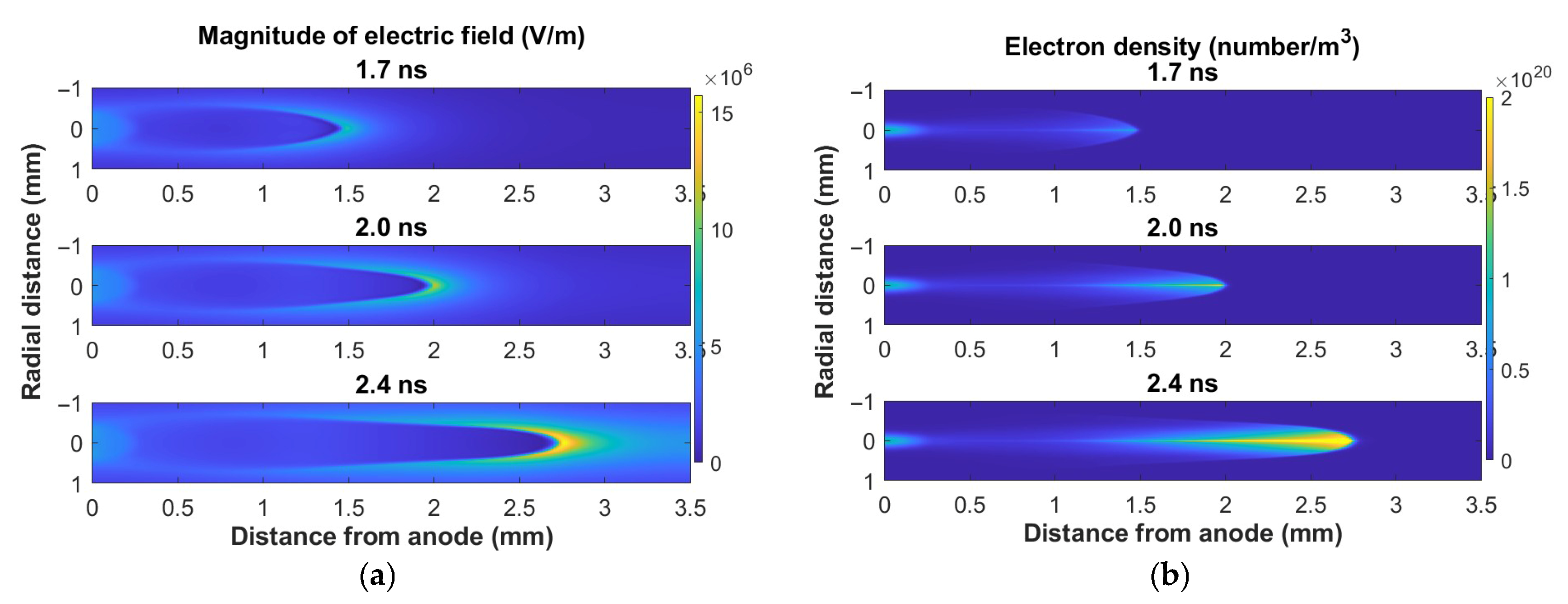
Figure 1. The cross-sectional image of a plane–plane electrode geometry at different times for a cathode-directed streamer: (a) electric field magnitude, and (b) electron density. The applied voltage was 15 kV at atmospheric pressure.
Plasma 08 00042 g001
Figure 2. The cross-sectional image of a pin–plane electrode geometry at different times for a cathode-directed streamer: (a) electric field magnitude, and (b) electron density. The applied voltage was 15 kV at atmospheric pressure.
Plasma 08 00042 g002
Figure 3. The cross-sectional image of a pin–pin electrode geometry at different times for cathode- and anode-directed streamers: (a) electric field magnitude, and (b) electron density. The applied voltage was 15 kV at atmospheric pressure.
Plasma 08 00042 g003
Figure 4. Streak images of the axial electron density and the axial electric field: (a) plane–plane geometry, (b) pin–plane geometry, and (c) pin–pin geometry. The simulation conditions are the same as in Figure 1, Figure 2, and Figure 3, respectively. Note: the color bar scaling is different for each plot.
Plasma 08 00042 g004aPlasma 08 00042 g004b
Figure 5. Electron density and electric field on axis. (a) Plane–plane electrodes at 1.8 ns; (b) pin–plane at 1.1 ns; (c) pin–pin at 1.0 ns. The time instances were chosen when the streamers reached approximately the middle of the gap.
Plasma 08 00042 g005
Figure 6. Time evolution of the discharge energy for the three electrode geometries.
Plasma 08 00042 g006
Figure 7. Dissociation rates for hydrogen and oxygen as a function of reduced electric field. The gas composition was N2 58%, O2 14%, and H2 28%.
Plasma 08 00042 g007
Figure 8. Hydrogen and oxygen G-factors for plane–plane, pin–plane and pin–pin electrode geometry.
Plasma 08 00042 g008
Figure 9. Spatial distribution of the energy density for the three electrode geometries.
Plasma 08 00042 g009
Figure 10. The volume associated with the energy density for a streamer in three different electrode geometries.
Plasma 08 00042 g010
Disclaimer/Publisher’s Note: The statements, opinions and data contained in all publications are solely those of the individual author(s) and contributor(s) and not of MDPI and/or the editor(s). MDPI and/or the editor(s) disclaim responsibility for any injury to people or property resulting from any ideas, methods, instructions or products referred to in the content.