Article

Study on Lightning-Induced Plasma Extinguishing in 10 kV Distribution Network Lines Based on Electronegative Gas Trifluoroiodomethane

by
Ping Huang
1,
Zhipeng Wu
2,*,
Li Tian
3,
Biao Zhang
2,
Yuang Long
2,
Zhenyu Liu
2 and
Yiyi Zhang
2
1
Guangxi Key Laboratory of Power System Optimization and Energy Technology, Guangxi University, Nanning 530004, China
2
School of Electrical Engineering, Guangxi University, Nanning 530004, China
3
Wuzhou Bureau of Extra High Voltage Transmission Company, China Southern Power Grid Co., Ltd., Wuzhou 543002, China
*
Author to whom correspondence should be addressed.
Plasma 2025, 8(3), 37; https://doi.org/10.3390/plasma8030037
Submission received: 18 August 2025 / Revised: 11 September 2025 / Accepted: 17 September 2025 / Published: 19 September 2025

Abstract

Plasma arcs generated by lightning strikes are prone to tripping distribution lines, especially 10 kV lines. To reduce the lightning-induced tripping rate of 10 kV distribution lines and ensure the safe operation of power systems, this paper proposes a same-level double-fracture lightning protection device containing the electronegative gas trifluoroiodomethane (CF3I). A mathematical model of the gas arc-extinguishing process is established based on magnetohydrodynamics. Meanwhile, the mechanism of CF3I in the arc-extinguishing process is analyzed according to its physical and chemical properties, and the arc-extinguishing process is simulated using COMSOL Multiphysics 6.0. The results show that (1) the arc-extinguishing effect is optimal when the horizontal distance of the compression pipeline of the device is 9 mm; (2) under the action of power frequency currents with different initial phases of π/2 and 0, the arc-extinguishing device can extinguish the arc within 800 μ s without re-ignition; and (3) in the arc-extinguishing process involving CF3I, the arc can be extinguished within 710 μ s , which is 11.2% quicker than that without CF3I. Meanwhile, CF3I can effectively reduce the arc temperature at the initial stage of arc extinguishing, avoiding damage caused by excessive internal compression of the device.

1. Introduction

Lightning strike is an intense atmospheric discharge phenomenon accompanied by high heat release and huge impact force. The plasma arc generated by lightning connects the line to the ground, which is prone to causing line short-circuit tripping and is the primary factor threatening the normal operation of distribution lines [1]. Distribution network lines are characterized by a large scale, complex structure, and wide distribution range. Their insulation strength and lightning-withstand level are both much lower than those of overhead transmission lines, making them extremely prone to line tripping when encountering overvoltages caused by direct lightning strikes or induced lightning [2]. According to statistics, in Hunan Province, China, the lightning-induced tripping rate of 35~220 kV overhead lines accounted for 81.43% of the total tripping rate in 2018, among which the lightning-induced tripping rate of distribution lines with 35 kV and below accounted for more than 90% [3]. Therefore, distribution lines have always been a weak point in the lightning protection of power grids. How to quickly extinguish the plasma arcs generated by lightning strikes and reduce the lightning-induced tripping rate of distribution lines has become a major challenge in the operation of modern power grids.
In recent years, research teams both domestically and internationally have conducted extensive studies on lightning protection and arc suppression. The current lightning protection and arc suppression methods can be broadly categorized into three types: blocking-type, diversion-type, and combined-type. Blocking-type lightning protection primarily involves installing lightning conductors and reducing ground resistance to lower the ground resistance of towers [4]. Diversion-type lightning protection primarily involves installing parallel gaps to redirect the power frequency arc generated by lightning strikes toward the system itself, thereby preventing arcs from flowing along insulator surfaces to the ground and causing short circuits or tripping [5]. However, this arc extinction method has the drawback of being unable to effectively extinguish arcs; combined-type lightning protection adds arc extinction measures to parallel gaps. T. Chino and M. Iwata propose a bell-shaped arc-extinguishing device made of polyvinyl chloride (PVC), which utilizes the heat generated by the arc to vaporize and eject PVC, causing the arc to deform and eventually extinguish [6]; G. V. Podporkin and A. D. Sivaev propose a multi-chamber arc-extinguishing device made of rubber. The arc breaks through the gap between the electrodes, and the air is blown out after being heated in the narrow gap between the electrodes, significantly extending the arc’s movement path and making it difficult to sustain combustion [7]; The High-Voltage Lightning Protection Team of Guangxi University has long been dedicated to lightning protection engineering for transmission lines and has proposed various lightning protection gaps with active arc-extinguishing functions. Among these, the more well-known ones are the compression-type arc-extinguishing device and the solid-phase gas arc-extinguishing device. The former extinguishes the arc by utilizing the high-speed airflow generated from the arc’s Joule heat, while the latter relies on the high-speed airflow produced by the explosion of gas pellets. However, their widespread use has been limited due to the need for frequent replacement of the gas-generating materials [8,9,10,11,12,13]. Subsequently, the team improved the solid-phase gas arc-extinguishing device, significantly reducing the arc extinction time and demonstrating its practicality through engineering applications; however, the issue of frequent replenishment of gas-generating raw materials still remains [14]. Congzhen Xie and his team propose a self-disconnecting lightning protection arc-extinguishing device that uses the heat generated by the arc to ignite gas-producing materials inside the arc-extinguishing cylinder, causing high-speed gas flows to be ejected from the outlet, enhancing the arc’s ability to dissipate power and forcing the arc to extinguish; however, the gas-generating materials can only be used once, making them inconvenient for long-term use [15]; Yang Tingfang’s team propose an arc-extinguishing device based on the magnetic energy gas-blowing principle that uses the potential energy generated by the arc introduced into the coil to drive a piston to compress air and act on the arc root, thereby extinguishing the arc, but it shows limited effectiveness against lightning strikes with long wave tail times [16].
Electronegative gases, as high-quality insulating media, are widely used in various electrical equipment. CF3I is a new type of electronegative gas and is regarded as a substitute for SF6 due to its low greenhouse effect. The Global Warming Potential (GWP) value of CF3I is 1–5, which is much lower than that of SF6 (23,900), and it is gradually replacing SF6 [17]. P. Widger et al. studied the breakdown characteristics of CF3I/CO2 mixed gas in vacuum circuit breakers and proved that it has good insulation strength at a pressure of 0.4 Pa [18]. Cardiff University conducted research on the SF6 substitution characteristics of CF3I and its mixed gases from the perspective of insulation properties. The results showed that the insulation strength of the CF3I/CO2 mixed gas with a 30% mixing ratio is equivalent to that of pure SF6 gas, and it increases with the pressure [19]. Zhang Xiaoxing’s team studied the discharge characteristics of CF3I gas and its mixed gases, proving that under standard atmospheric pressure, the breakdown voltage of pure CF3I is 1.2 times that of SF6, and the partial discharge inception voltage of CF3I-CO2 is 0.9–1.1 times that of SF6-CO2 [20]. Xiao Dengming’s team analyzed the insulation properties of CF3I and its mixed gases using the Boltzmann equation, and the results showed that when the content of CF3I reaches 70% or more, the insulation level of CF3I/CO2 and CF3I/N2 mixed gases exceeds that of pure SF6 gas [21]. At present, the application of electronegative gases in power systems is concentrated on gas insulation for circuit breakers and transformers, with relatively few applications in the field of lightning protection and arc extinguishing. The plasma generated by lightning strikes contains a large number of high-energy electrons, which continuously ionize molecules in the air and maintain arc combustion. Electronegative gases possess strong electron adsorbing properties. They can easily capture electrons during a lightning flashover, inhibit the collision and ionization of particles within the plasma arc, reduce the temperature inside the device at the initial stage of arc extinguishing, prevent damage to the lightning protection device caused by excessive internal pressure, and shorten the arc extinguishing time.
To address the deficiencies in lightning protection for 10 kV distribution lines and accelerate the extinguishing process of lightning-induced plasma, this paper proposes a novel same-layer double-break compressed lightning protection structure and applies the electronegative gas CF3I to lightning arc extinguishing. The paper establishes a mathematical model of plasma arcs, analyzes the principles of arc compression and gas expansion processes, and examines their operational mechanism during the arc-extinguishing process. The COMSOL Multiphysics finite element software is used to simulate the arc-extinguishing effect of the device, and the changes in temperature and gas flow velocity during the arc-extinguishing process of the device are analyzed.

2. Mathematical Model of Plasma Arc and Principle of Deionization

2.1. Structure of the Same-Layer Double-Break Compressed Lightning Protection Device

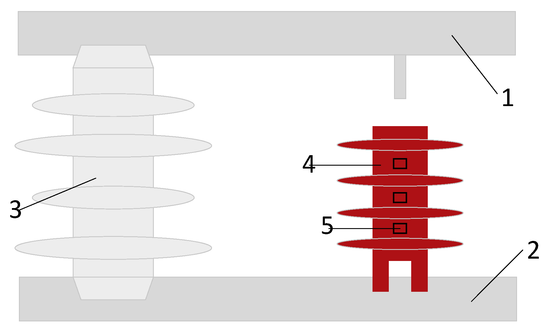
Figure 1 shows the structural diagram of a same-layer double-break compression lightning protection device. The device consists of insulated housing and two lightning arrestor electrodes. In the figure, 2 are the lightning arrestor electrodes of the device: 3 is the insulated housing; 4 is the exhaust port structure; A is the simulated temperature monitoring point; 1 is the high-voltage electrode; 5 is the grounding electrode; and 6 is the tin spheres containing CF3I gas. The vertical distance from the high-voltage electrode 1 to the ground electrode 5 is 84 mm, the overall width of the arc-extinguishing device is 46 mm, and the red line segment represents the direction of the plasma arc when the line is struck by lightning. The arc-extinguishing device proposed in this study is installed in parallel with the insulator, and there is an air gap directly between the lightning arrester electrode of the distribution line and the lightning arrester, as shown in Figure 2. In Figure 2, 1 is the distribution line; 2 is the grounding terminal; 3 is the insulator; 4 is the same-layer double-break arc-extinguishing device; and 5 is the exhaust port of the arc-extinguishing device.

2.2. Plasma Model Analysis

The high-temperature plasma generated by lightning strikes is known as an electric arc. To describe the gas arc-quenching process, this paper establishes a magnetohydrodynamic model based on the coupling of electromagnetic fields and fluid heat transfer fields. To describe the gas discharge phenomenon, the following simplifications are made to the gas discharge process [22,23,24]: (1) The arc is a high-temperature plasma that satisfies local thermodynamic equilibrium (LTE); (2) the electrical conductivity, thermal conductivity, and specific heat capacity of the air in the discharge region are all single-valued functions of temperature; (3) the device is an incompressible rigid body with no slippage on the walls; and (4) the air domain containing the arc is a compressible laminar flow.
Based on the above assumptions, the arc equation established under local thermodynamic equilibrium conditions is modeled and analyzed using the Navier–StokesNavier-Stokes equation and Maxwell’s equations:
Law of conservation of mass:
ρ t + · ρ V = 0 .
Momentum conservation equation:
ρ V t + ρ V · V = · p I + K + F K = μ V + V T 2 3 μ · V I F = J × B .
Energy conservation equation:
ρ h t + · ρ V h = · k T + Q .
Q = P t S R + J × E + Φ .
Gas equation:
P = ρ R T .
Current conservation equation:
· σ ϕ = 0 E = ϕ J = σ · E .
Magnetic field conservation equation:
× H = J E = A t B = × A ,
where ρ —fluid density; μ —fluid viscosity coefficient; σ —conductivity; ϕ —electric potential; Φ —viscous dissipation; h —enthalpy value; k —thermal conductivity of gases; S R —radiation source quantity; T —temperature; I —unit matrix; t —time; V —speed of air; R —gas constant; P —pressure; E —electric field strength; J —current density; B —magnetic flux density; H —magnetic field strength; A —magnetic vector potential.

2.3. Analysis of Plasma Deionization Process in a Same-Layer Double-Break Compression Lightning Protection Device

The breakdown voltage of the lightning protection device is lower than that of the insulator. When the line is struck by lightning, the flashover path will preferentially pass through the lightning protection device. When lightning strikes the lightning protection device, the internal structure of the device makes the arc move along a tortuous discharge path, thereby extending the arc discharge path and diluting the high-temperature particle density during the combustion process. As shown in Figure 1, without the arc-extinguishing device, the movement distance of the plasma arc during a lightning strike is from the high-voltage electrode 1 to the ground electrode 5, totaling 84 mm. After the lightning protection and arc-extinguishing device is installed, the movement distance of the plasma arc becomes the red line segment—where the horizontal segment represents the extended distance—and the total distance is 136 mm, lengthening the arc by 61.9%. The compression channels within the device subject the arc to cold-wall compression. The arc’s own expansion exerts pressure on the pipe walls, while the pipe walls exert a counterforce on the arc, preventing its radius from continuing to expand and confining it within the pipe. Cold-wall compression primarily occurs during the early stages of gas breakdown, when the thermal expansion of the gas and plasma is extremely intense, making the effect of cold-wall compression more pronounced.
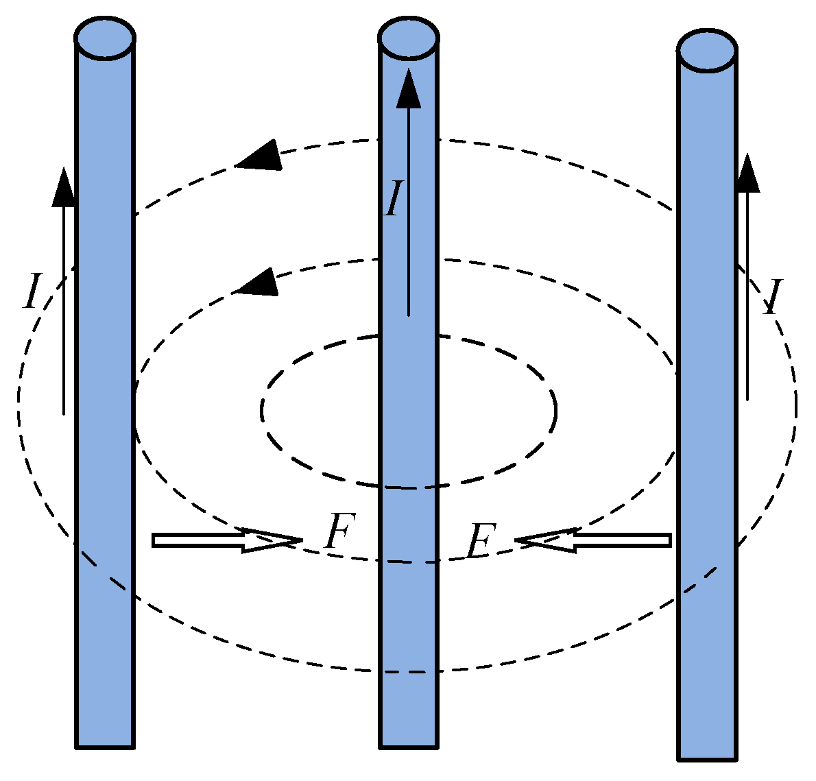
The arc in the compression pipe is also subject to self-magnetic compression. Essentially, a plasma arc is an electric current, and its diameter will gradually be compressed and reduced under the influence of the Ampère force. If the arc is regarded as being composed of numerous tiny unit currents in the same direction, each unit current will generate an induced magnetic field around it, and the surrounding currents will be attracted toward it by the Ampère force in this magnetic field. Therefore, countless segments of unit currents will move toward the center of the plasma, resulting in the compression of the arc diameter. As shown in Figure 3. If we consider the cross-section of the arc as circular, with a current density j = I π r 2 [25], then the pressure difference at any point in the arc within the compression channel relative to the edge of the arc column is the following [26]:
Δ P ( r ) = μ 0 I 2 π r 2 1 r 2 r 2 .
When r = 0, the pressure difference at the center of the arc column reaches its maximum:
Δ P 0 = μ 0 I 2 4 π 2 r 2 .
In the equation, r is the distance from a certain section of the arc column to the center axis of the arc; r is the radius of the arc column; μ 0 is the magnetic permeability of vacuum; I is the current of the arc.
From the above equation, it can be seen that the pressure difference exerted on the arc by magnetic compression is inversely proportional to the square of the arc radius. Under the combined effect of these two compression methods, the arc forms an extremely compressed state in the compression pipe, causing the arc radius to undergo significant changes on both sides of the compression pipe and forming multiple unstable weak points.
There are three ways in which plasma arc energy is dissipated: radiative heat dissipation, conductive heat dissipation, and convective heat dissipation. Radiative heat dissipation is more pronounced in larger arcs, but since the arcs discussed in this paper are small, it can be ignored. Conductive heat dissipation is a spontaneous phenomenon of heat transfer between different media, from high temperature to low temperature. Assuming that the arc has a radius of r , the conductive heat dissipation power is the following [27]:
P = 2 π λ T ( T T 0 ) ln r 0 ln r ,
where λ T —thermal conductivity; T —temperature at a distance r 0 from the center of the arc column; T 0 —initial temperature of the surrounding air.
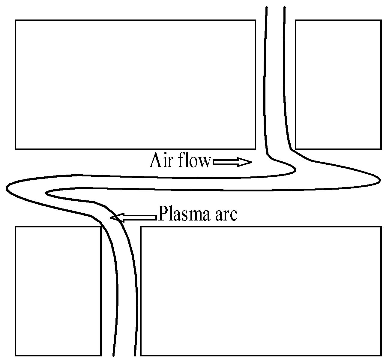
Convective heat dissipation is the primary arc-quenching method in the arc combustion process. The arc releases heat within the device, accelerating airflow in the arc-quenching chamber to form high-speed gas flows. In the central portion of the arc-quenching chamber, the arc is subjected to longitudinal blowing to further reduce its diameter. Additionally, the arc is subjected to transverse blowing at the weak inflection points on the upper and lower sides of the compression channel, causing multiple breakpoints to form in the arc during its movement, significantly enhancing the convective interaction between the arc and the air. This greatly suppresses the development of the arc during its initial stages, thereby improving arc extinction efficiency, as shown in Figure 4. Assuming that the airflow velocity is v and the arc radius is r , the gas volumes passing through the arc in the longitudinal and transverse airflow per unit time are v π r 2 , 2 r v , respectively. Then, the heat dissipation power during the process of the air temperature rising T 0 to T 1 is the following [28]:
P z = v π r 2 T 0 T 1 c d T P h = 2 r v T 0 T 1 c d T ,
where c is the specific heat capacity of air.
During the combustion of an arc, it contains a large number of high-velocity, low-mass electrons and low-velocity, high-mass ions. High-speed electrons tend to combine with neutrons during collisions to form ions and more electrons, further accelerating air ionization to generate an electron avalanche. Electronegative gases possess a strong electron adsorption capacity and can easily capture free electrons in the air. Meanwhile, C F 3 I has a relatively large molecular weight, resulting in slow movement speed and a large mean free path, making it less likely to collide with other particles. In addition, the process of electron adsorption by C F 3 I is accompanied by thermal decomposition and electrical decomposition, both of which are endothermic reactions; these reactions can absorb the heat generated by lightning strikes. As shown in Equations (12)–(15) [29]. C F 3 I plays a role in the initial stage of the arc-extinguishing process. On one hand, it inhibits ionization by utilizing its own electron-adsorbing property; on the other hand, it absorbs heat through its own thermal decomposition, thereby reducing the temperature during the initial arc-extinguishing process.
C F 3 I + e C F 3 + I + e Δ H = 336.13 kJ / mol
C F 3 I + e C F 3 + I Δ H = 223.86 kJ / mol
C F 3 I C F 3 + I + + e Δ H = 1092.71 kJ / mol
C F 3 I C F 3 + + I + e Δ H = 1072.00 kJ / mol
In the formula, e * represents a high-energy electron, CF 3 and I denotes the free radical corresponding to the molecular group; free radicals contain unpaired electrons, exhibit active chemical properties, and easily undergo chemical reactions with other substances.

2.4. Plasma Arc Extinction Criteria

The energy relationship of the plasma arc stable combustion process can be expressed by the following equation [30,31]:
P s = P c d + P d l + P f
where P s —arc energy of arc; P c d —arc conduction heat dissipation power; P d l —Convective heat dissipation power; P f —Radiant heat dissipation power.
When the arc energy exceeds the energy dissipation, the arc continues to heat up; when the arc energy equals the energy dissipation, the arc is in a stable combustion state; when the arc is subjected to strong airflow, the convective heat dissipation power increases sharply, causing the combustion equation to become unbalanced, with the arc energy dissipation power exceeding the emitted power, leading the arc to tend toward extinction. Based on engineering experience, when the arc temperature is below 3000 K, the arc can be considered extinguished.

3. Simulation Analysis

3.1. Simulation Condition

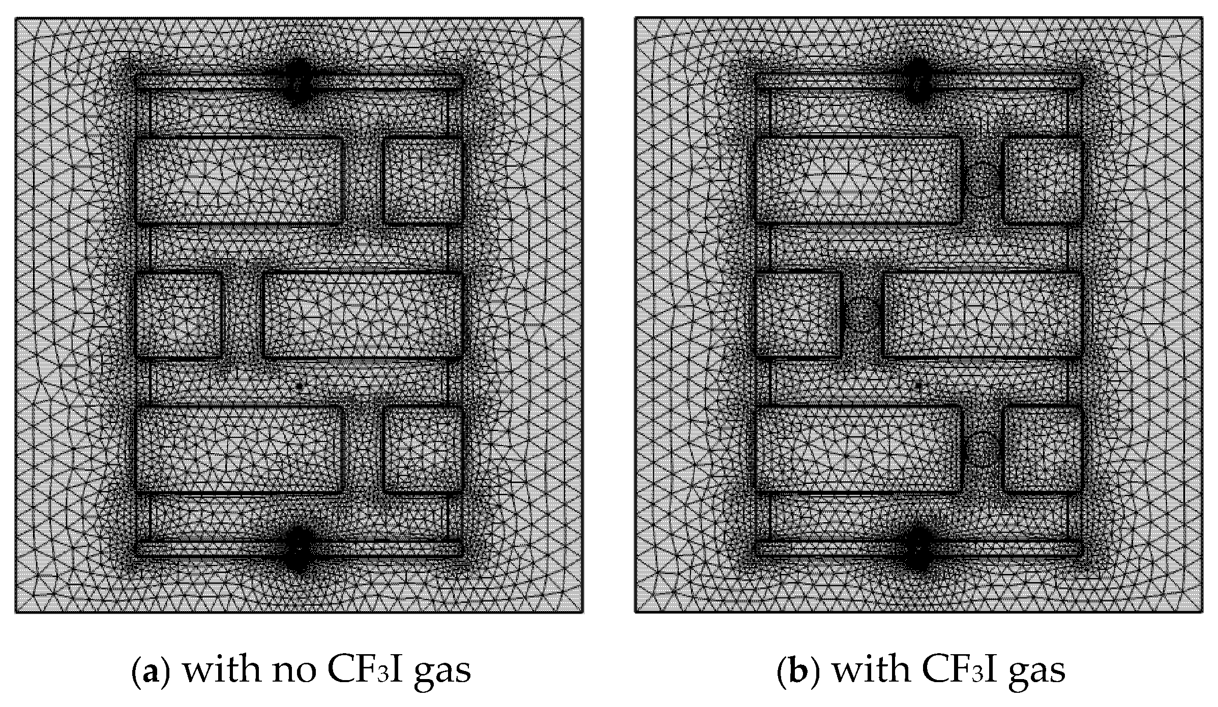
The simulation section was conducted using the COMSOL Multiphysics finite element simulation software. Based on the simplification in Section 2.1, the simulation set the initial air temperature at 293.15 K and the initial pressure at one standard atmospheric pressure. The research object of this paper is the lightning protection of 10 kV lines. According to actual engineering specifications, 10 kV lines mainly supply power to urban areas and factories, with conductor cross-sectional areas ranging from 50 mm2 to 185 mm2. The current-carrying capacity of the line increases as the conductor’s cross-sectional area increases. When 10 kV lines supply power to large-capacity industrial users, the conductor cross-sectional area adopted is 185 mm2, and the line current-carrying capacity ranges from 410 A to 460 A. The power frequency current used in this paper has an amplitude of 0.5 kA, a frequency of 50 Hz, and a sinusoidal waveform; the lightning current waveform is 8/20 μ s with an amplitude of 50 kA, and the ground electrode voltage is set to 0 V. The boundary outlet condition is one standard atmospheric pressure. For the simulation, the lead-in electrode, high-voltage electrode, and grounding electrode are made of copper, the insulating shell is made of ceramic, and the remaining parts are set as air. The simulation uses the Pardiso solver with a solution step size of 10 and a total simulation time of 10 ms. The mesh adopts a physics-controlled grid is show in Figure 5.
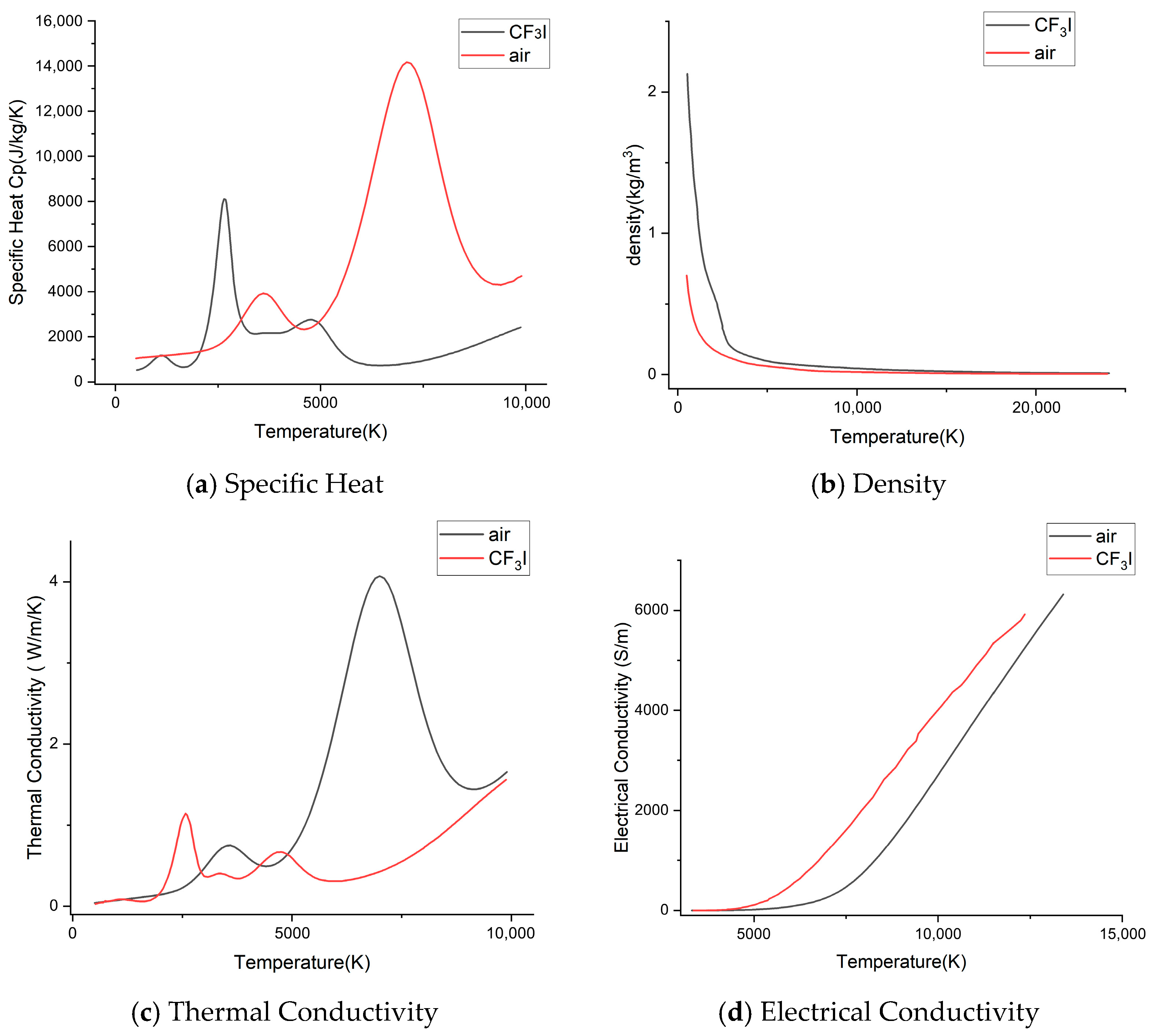
Meanwhile, in this paper, simulation control experiments on the arc-extinguishing device containing C F 3 I are conducted under the action of power frequency currents with initial phases of π / 2 and 0. Various thermal properties of C F 3 I at different temperatures are collected and compared with those of air [32,33,34], as shown in Figure 6. To simplify the simulation process and ignore the interference factors that affect the experimental results, further simplifications are made to C F 3 I under the assumptions in Section 2.1: (1) the melting process of the tin foil shell is ignored, and (2) the supporting structure of the tin foil balls in the compression pipeline is ignored.

3.2. Comparison of Arc-Extinguishing Effects at Different Horizontal Distances of Compressed Pipelines

The horizontal distance of the compression pipe refers to the distance between the centerline of the pipe and the straight line connecting the upper and lower electrodes. The horizontal distance of the compression pipe determines the extent to which the lightning arc is elongated, which has a critical impact on the arc-quenching process of the device. This paper conducts simulation analyses for horizontal distances of 8 mm, 9 mm, and 10 mm, and compares the temperature changes at point A under different distances.
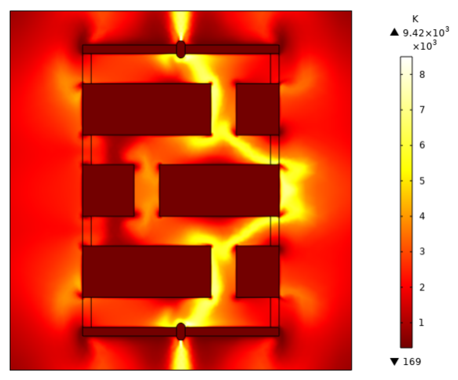
As shown in Figure 7, the temperature change trends are consistent across the three horizontal distances. In the initial stage of the arc-extinguishing process, the temperature changes at horizontal distances of 8 mm and 9 mm are similar, but both are higher than at 10 mm. During the phase where the power frequency current energy competes with airflow cooling after the lightning flash discharge disappears, the temperature at 10 mm is higher than the other two at 3000 μ s , but from 3000 μ s until the simulation ends, the 9 mm curve is consistently lower than the 8 mm curve, while the 10 mm temperature is significantly lower than the other two. In Figure 7, the 10-mm curve’s decline rate is significantly higher than the other two, indicating the fastest temperature drop, but this does not imply that the 10 mm horizontal distance has the best arc-quenching effect. As shown in Figure 8, an excessively long horizontal distance prevents the arc from moving along the pre-set tortuous path inside the device and instead causes it to choose a shorter path, resulting in flashover occurring outside the device. External flashover does not undergo processes such as narrow channel compression or elongation, making it difficult to form high-speed gas flows to extinguish the arc, and it is highly prone to forming power frequency arcs under the influence of power frequency current. Based on the above simulation analysis, this paper further analyzes the horizontal compression pipe distance device with a horizontal distance of 9 mm.

3.3. Comparison of Arc-Extinguishing Effects Based on Different Initial Phases

The initial phase of the power frequency current has a significant impact on arc extinction. A power frequency current with an initial phase of π / 2 exhibits a trend of first decreasing and then increasing after a lightning flashover, while a current with an initial phase of 0 first increases and then decreases after a lightning flashover. The change in the power frequency current determines the trend of air energy changes after the flashover. This section first analyzes the temperature change comparison chart at point A and then analyzes the temperature and velocity change cloud maps during the arc-extinguishing process of the device to study the energy changes during the operation of the device, thereby verifying the rationality of its arc-extinguishing performance.
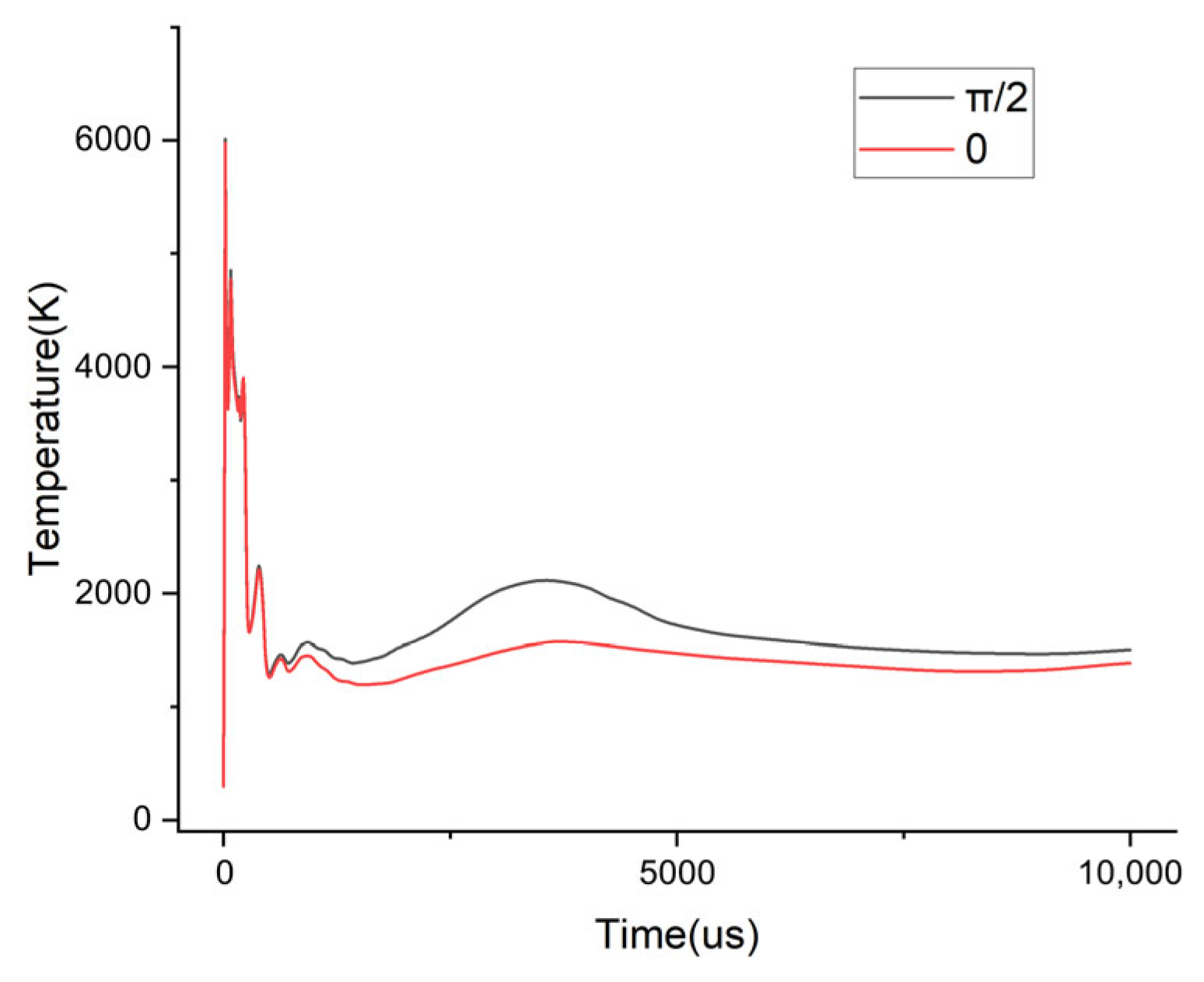
Figure 9 shows the temperature variation process at Point A under different initial phases. In the initial stage of arc extinguishing, the curves show basically the same trend. After the impulse current disappears, the curve with the initial phase of π / 2 continues to stay above the curve with the initial phase of 0, but the overall difference is not significant. The results indicate that in both simulations, the temperature at Point A can drop rapidly to below 3000 K, and even under the power supply of the industrial frequency current, it fails to rise back to 3000 K, which preliminarily demonstrates the arc-extinguishing effectiveness of the device proposed in this study.

3.3.1. Analysis of the Overall Arc-Extinguishing Effect of Power Frequency Current with an Initial Phase of π / 2

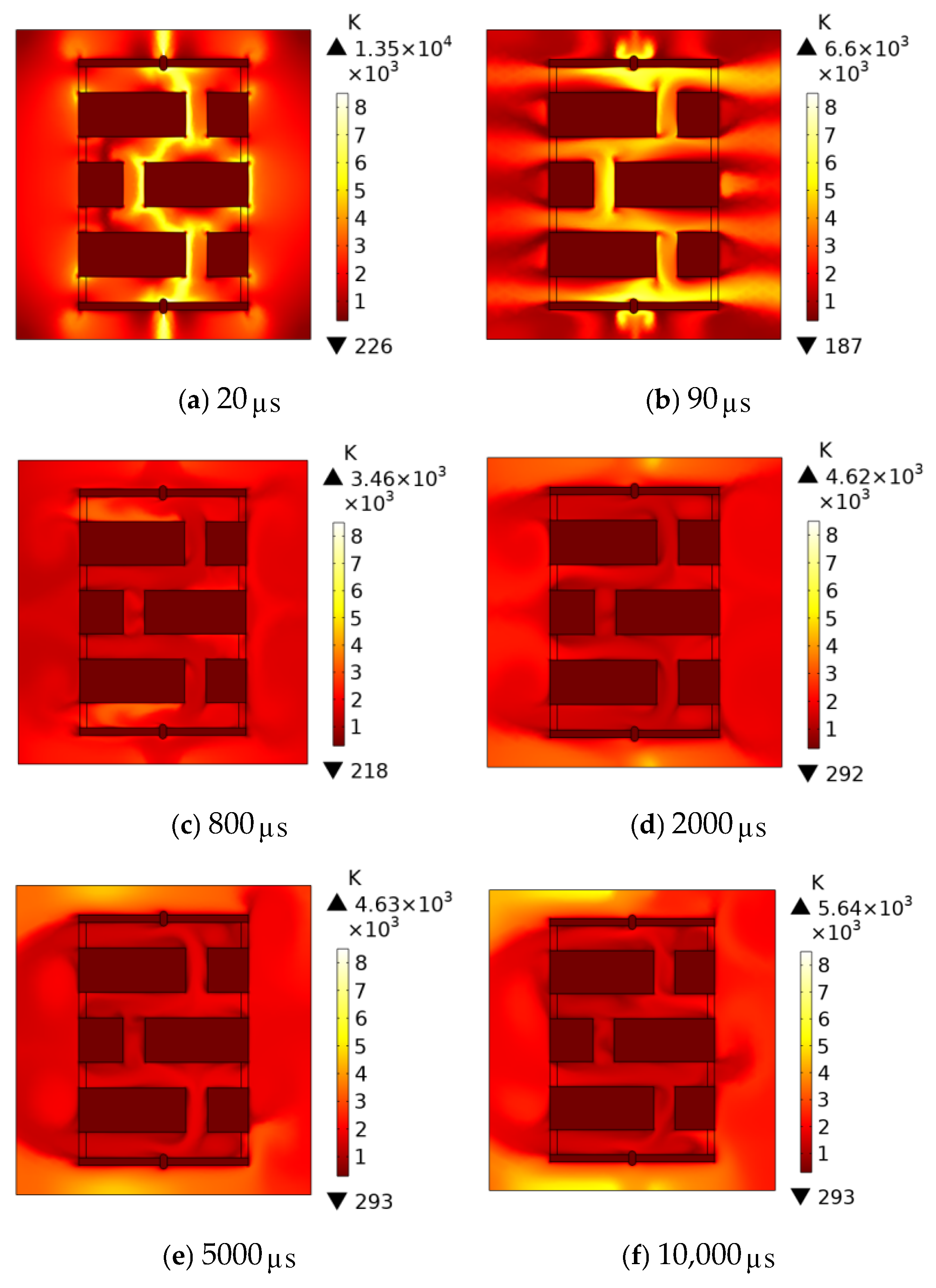
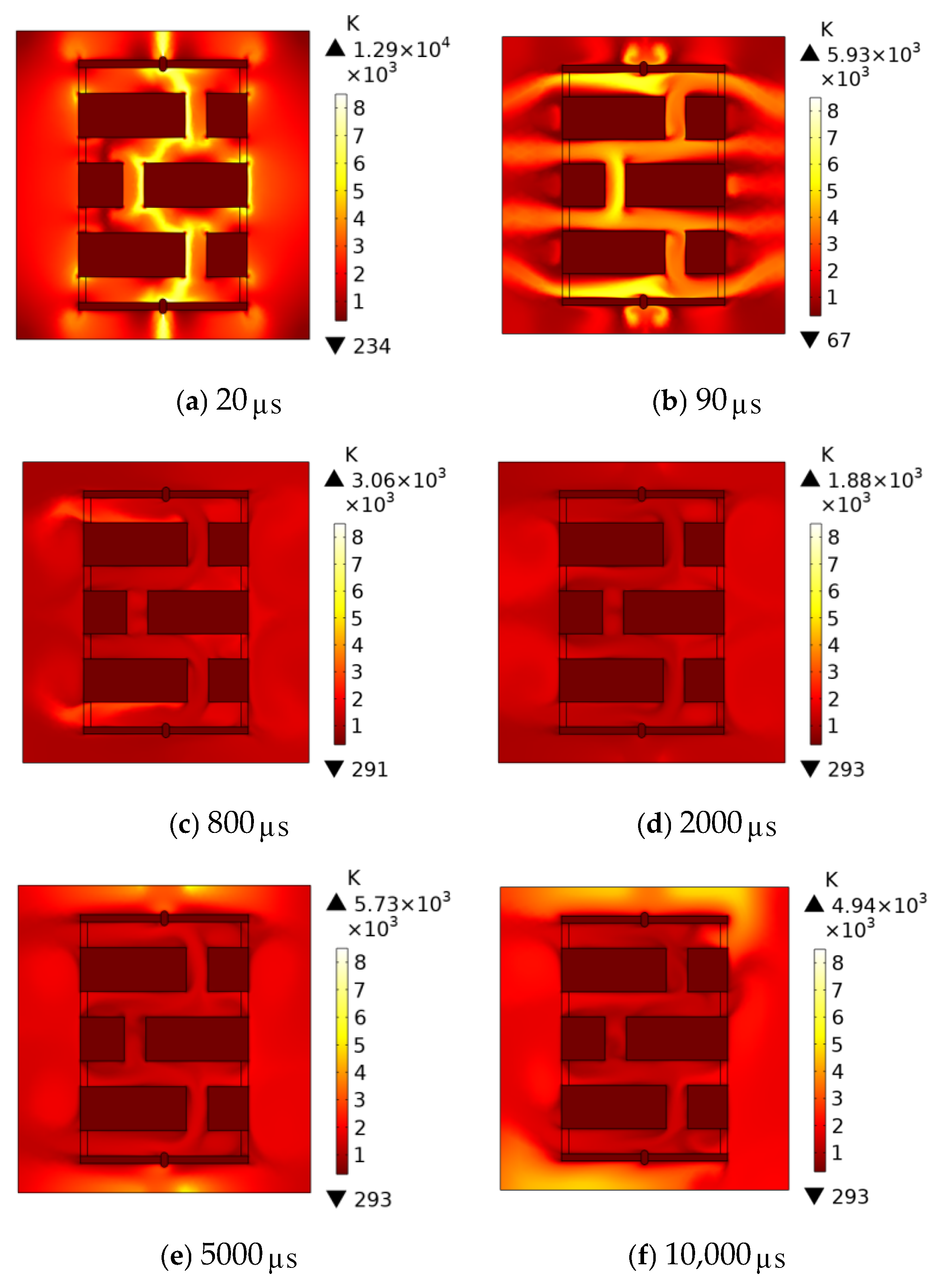
Figure 10 is a diagram showing the temperature variation during the arc-extinguishing process of the power frequency current with an initial phase of π / 2 . The temperature changes lag behind the lightning current changes. When the lightning current decays to half its value at 20 μ s , the peak of the lightning current has just passed, leaving a large amount of heat trapped inside the device with no means to dissipate. Therefore, at this point, the accumulated temperature reaches its peak, causing the device to break down and flash over, with the temperature rising to approximately 13,521 K. Thereafter, the lightning current rapidly decreases. The heat generated by the flashover causes the air to expand rapidly, expelling the arc outside the device. By 90 μ s , the arc is completely blown apart, and the lightning current flashover has largely disappeared, with the power frequency current beginning to take effect. Between 90 μ s and 800 μ s , due to the high airflow velocity and strong air movement, convective heat dissipation is significant, the heat generated by the power frequency current is not prominent, and the temperature inside the device continues to decrease, reaching a minimum of approximately 3000 K at 800 μ s , as shown in Figure 10c. From 800 μ s to 5000 μ s , the power frequency current competes with air convection and conduction for heat dissipation. The power frequency current continuously supplies energy to the high-temperature gas, while airflow causes heat to diffuse outward. By the time the current crosses zero at 5000 μ s , except for some high-temperature regions near the upper and lower electrodes, the rest of the areas have dropped below 3000 K, and no arc rekindling occurs. After 5000 μ s , the power frequency current gradually increases, strengthening its influence on air convection, and the competition between heat transfer and heat dissipation intensifies further. At the moment when the power frequency current reverses to reach its maximum value at 10,000 μ s , the temperature near the high-voltage electrode and the grounding electrode is higher than that at 5000 μ s , but no arc reconstruction occurs within the air domain. The results indicate that the device successfully suppressed the generation of power frequency arc after a lightning strike.
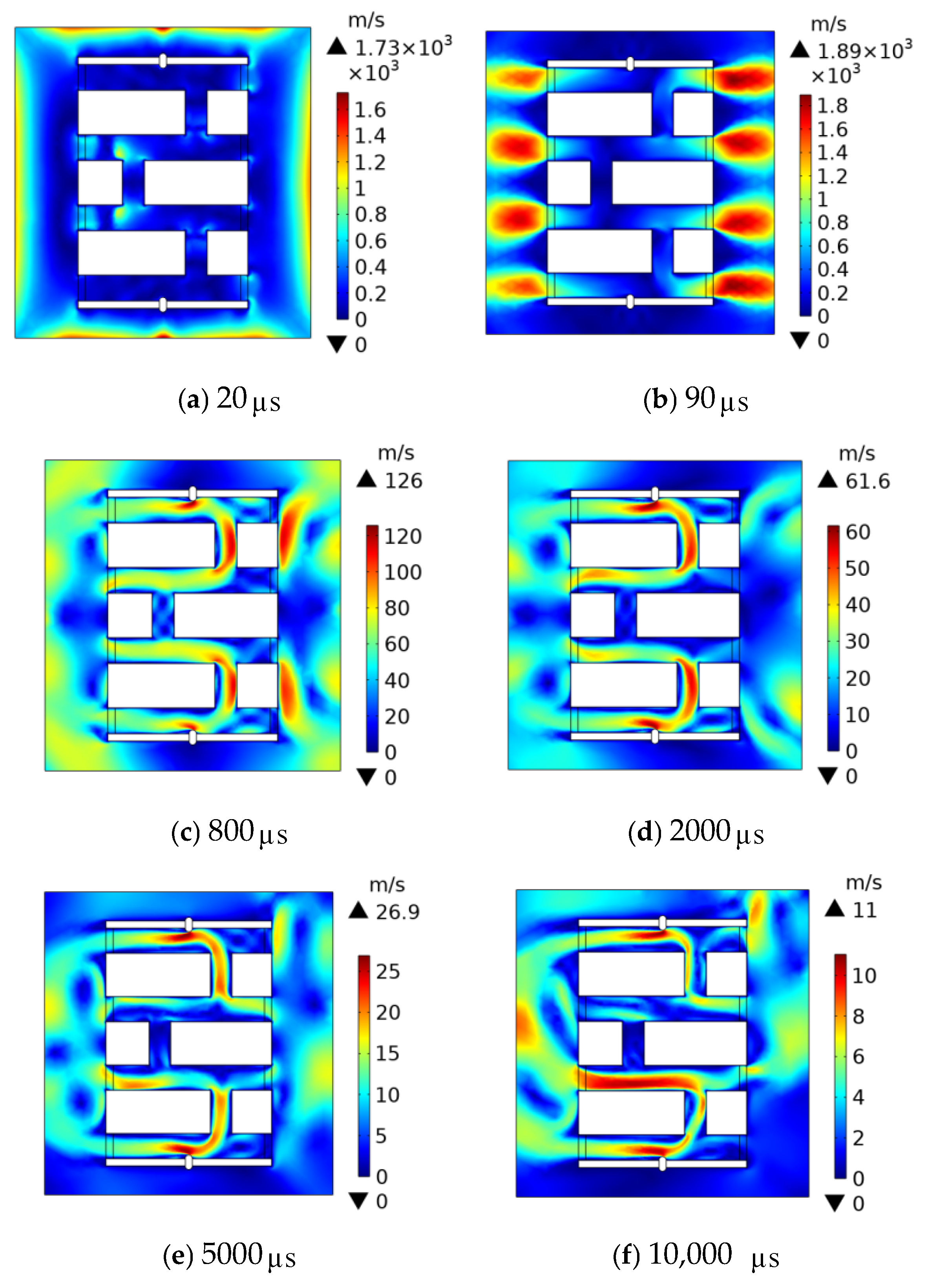
Figure 11 shows the velocity contour variations during the arc-extinguishing process with an initial phase of π / 2 . During the flashover stage at 20 μ s , the boundary velocity of the air domain is higher than the velocity within the domain. When the expansion flow caused by the flashover reaches the boundary, since the boundary is at standard atmospheric pressure lower than the pressure within the air domain, a significant pressure gradient forms near the boundary, accelerating the flow velocity. After 20 μ s , the expanding gas flow rapidly expels the arc outside the device. The gas flow changes lag behind temperature changes, and the gas flow velocity exceeds 1000 m/s at 90 μ s , reaching its peak, as shown in Figure 11b. After 90 μ s , the lightning peak disappears, and the airflow velocity decreases significantly. At this stage, there is a competition between the energy of the power frequency current and the heat dissipation of the airflow. The energy of the power frequency current provides energy for airflow, while the airflow accelerates convective heat transfer and particle diffusion. However, the degree of deionization during the flashover extinction stage affects this process. During this stage, the current’s energy contribution is not significant, so the air temperature gradually decreases, and the airflow velocity slows down. Between 800 μ s and 5000 μ s , the power frequency current energy gradually decreases, accompanied by a decrease in airflow velocity, until the current crosses zero at 5000 μ s , with the maximum velocity reaching only 26.9 m/s. During this process, due to the narrow channels within the device, the airflow velocity inside the device remains higher than that in the external air domain. After the current crosses zero at 5000 μ s , it gradually increases. However, due to the previous airflow causing significant heat loss and the diffusion of charged particles, the effect of the power frequency current is not prominent during this period, and the airflow velocity remains low, and the maximum at 10,000 μ s is 15.4 m/s.

3.3.2. Analysis of the Overall Arc-Extinguishing Effect of Power Frequency Current with an Initial Phase of 0

Figure 12 illustrates the temperature contour variations during the arc-extinguishing process with an initial phase of 0. The temperature difference during the arc extinction process with initial phases of 0 and π / 2 is not significant. Breakdown occurs at 20 μ s , at this point, the lightning current is much greater than the power frequency current, so there is no obvious difference between the initial stage temperature change and the initial phase. Followed by thermal expansion of the air, which then blows the flashover arc out of the device, until it is completely extinguished at 90 μ s . After 90 μ s , the flashover current gradually approaches 0 and under the influence of the gradually increasing power frequency current, the airflow velocity remains high at this point; the heat dissipation power exceeds the heat generation power, causing the temperature to gradually decrease. By 5000 μ s , when the current reaches its peak, the temperature in most areas has already dropped below 3000 K, as shown in Figure 12e. After 5000 μ s , the power frequency current gradually decreases, and the air temperature rises more slowly, but the overall temperature continues to rise until 10,000 μ s , when, except for some areas at the two electrodes, the temperature in the remaining regions is below 3000 K, and the arc cannot be reignited. The results demonstrate that the arc-extinguishing device proposed in this paper can successfully suppress the power frequency arc generated by lightning strikes at the initial phase angle of 0.
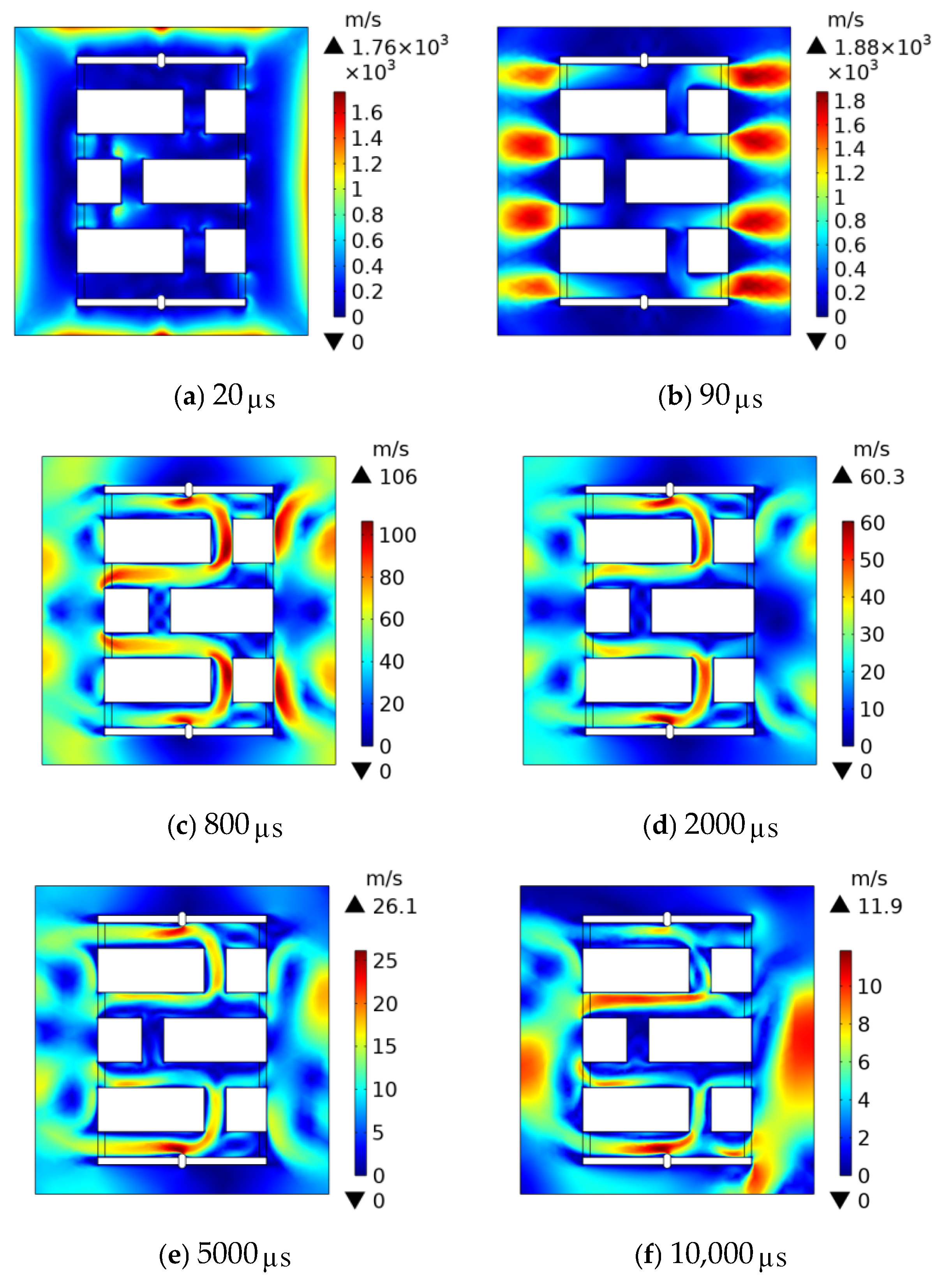
Figure 13 shows the velocity contour variations during the arc-extinguishing process with an initial phase of 0. The difference in extinguishing process speed between initial phases of 0 and π / 2 is also not significant. Similarly, at 20 μ s , the pressure gradient at the boundary causes the airflow velocity to exceed that of the gas within the domain; 20 μ s to 90 μ s is the arc-extinguishing stage, and complete extinguishing is achieved by 90 μ s , followed by a decrease in airflow velocity. After 90 μ s , the lightning current has largely dissipated, and the power frequency current begins to increase gradually. The competition between power frequency current and airflow cooling is more intense than at the phase, but overall, cooling exceeds heating. At 800 μ s , the velocity reaches 122 m/s. After 800 μ s , the power frequency current continues to increase, reaching a peak at 5000 μ s with an airflow velocity of 30 m/s. Under the subsequent influence of the airflow, the power frequency current gradually decreases, and the airflow velocity further decreases. At this point, there is no possibility of continued connection of the power frequency arc, and the arc extinction process is concluded.

3.4. Arc-Extinguishing Process with the Participation of Electronegative Gas C F 3 I

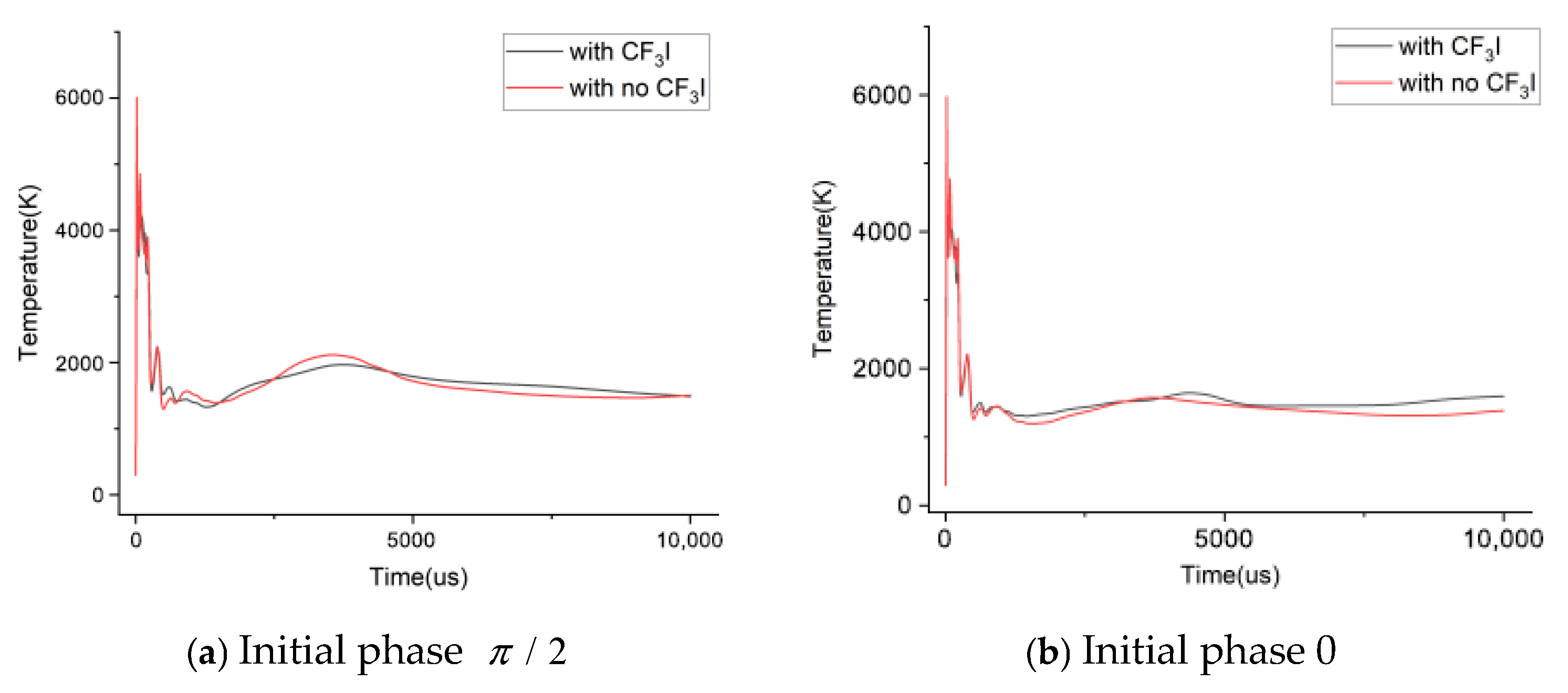
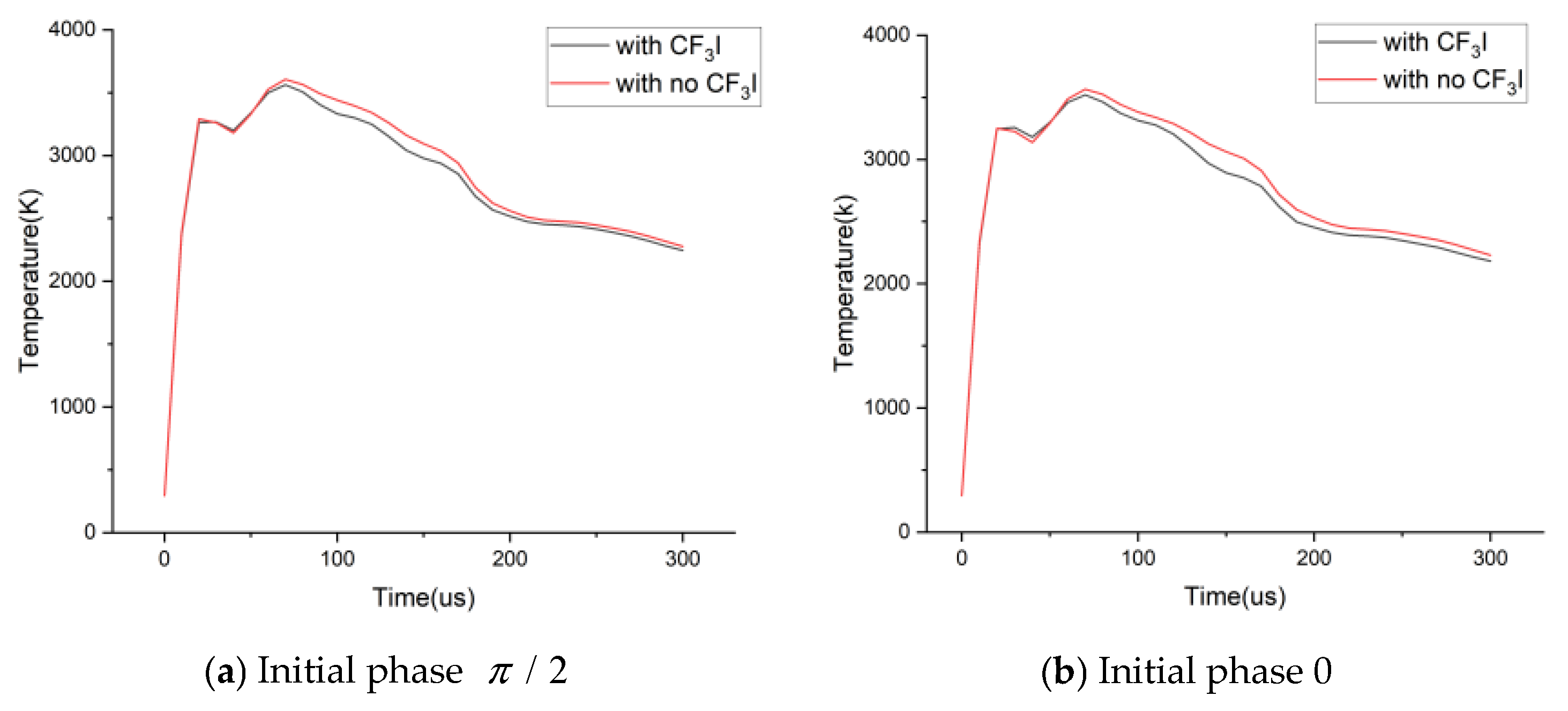
Figure 14 compares the temperature variation process at Point A under the action of power frequency currents with different initial phases. It can be seen from Figure 14a,b that regardless of the condition, the temperature at Point A can quickly drop below 3000 K. Although there are subsequent fluctuations, it never rises back to 3000 K. In the initial stage of arc extinguishing in Figure 14a,b, the temperature reduction in the arc-extinguishing process involving C F 3 I is more obvious. Specifically, the temperature decreases by approximately 500 K in the process with an initial phase of π / 2 , and by up to 1000 K in the process with an initial phase of 0. This is because a large number of high-speed electrons are generated during the breakdown of the arc-extinguishing device by lightning current. C F 3 I combines with these electrons to inhibit the initial air ionization. Meanwhile, the decomposition of C F 3 I successfully absorbs part of the heat, reducing the temperature at this stage, avoiding damage to the internal device caused by excessive pressure, and enhancing the practicality of the arc-extinguishing device. Figure 15 compares the average temperature of the air domain inside the device in the first 300 μ s under different conditions. The temperature in the process with C F 3 I participation is always lower than that without C F 3 I . However, the temperature reduction is not significant due to the limitation of the C F 3 I capacity inside the device. The above figures illustrate that C F 3 I can effectively suppress the arc temperature in the initial stage of arc extinguishing, thus protecting the arc-extinguishing device. In this paper, the arc-extinguishing process of the device will be analyzed in detail under the condition of an initial phase of 0.
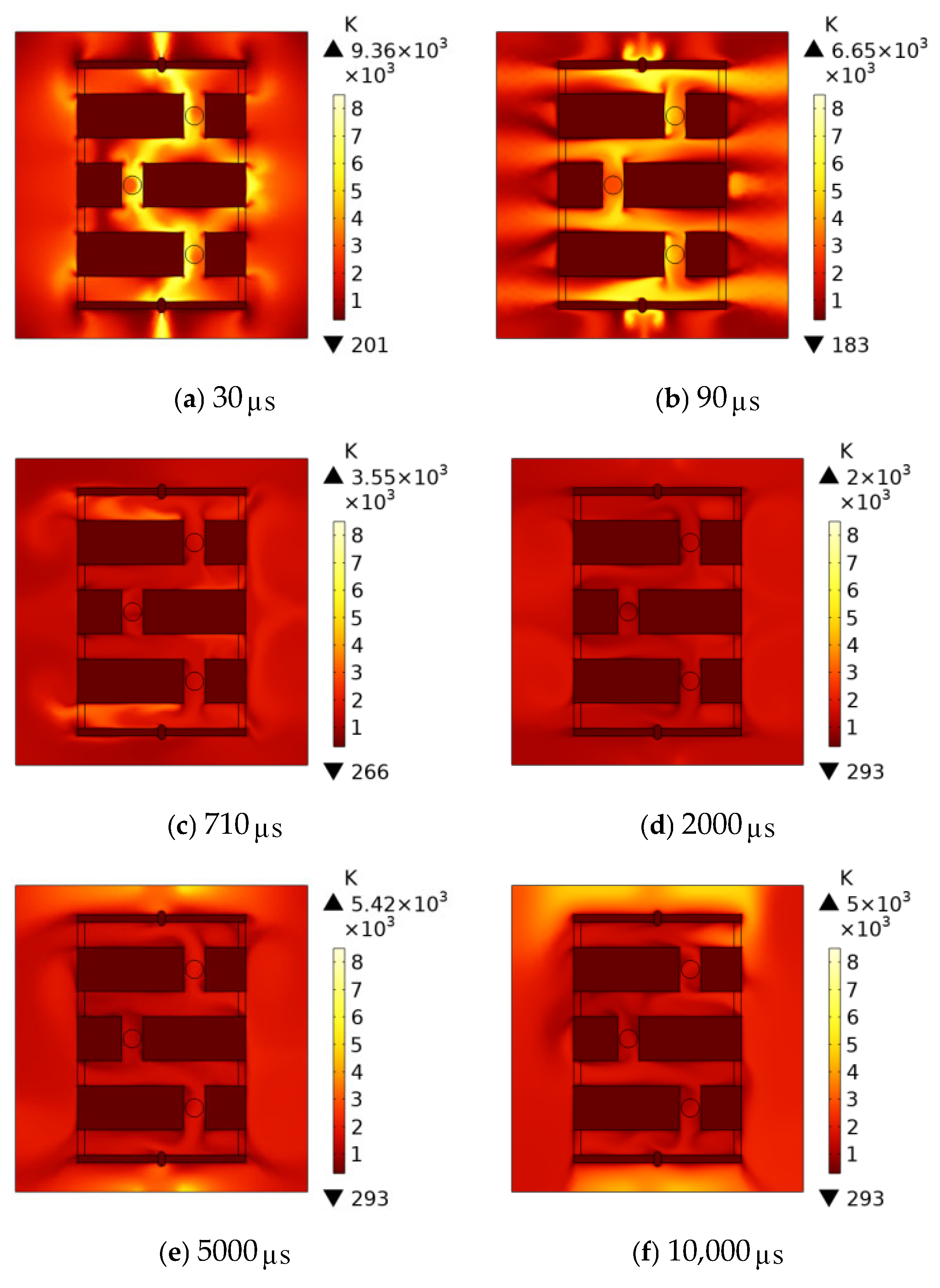
Figure 16 shows the temperature variation during the arc-extinguishing process with the participation of the electronegative gas C F 3 I . The lightning flashover occurs at 30 μ s , which is later than that in the arc-extinguishing process without CF3I participation. After that, the magnitude of the lightning current drops sharply, and at the same time, the air expands rapidly to blow the arc to the outside of the device, which is completely blown off at 90 μ s , as shown in Figure 16b. After 90 μ s , the lightning current disappears, and a gradually increasing power frequency current appears in the high-voltage electrode. The high-temperature gas inside the device undergoes conductive and convective heat dissipation. By 710 μ s , the temperature in most areas inside the device has dropped below 3000 K, and the arc is deemed to have been extinguished at this moment, with the arc-extinguishing time shortened by 11.2%. At this point, the power frequency current continues to decrease, and the temperature keeps dropping as the heat dissipation slows down. When the power frequency current reaches 0 at 5000 μ s , the temperature in all regions except the high-voltage electrode and the grounding electrode has dropped below 2000 K. From 5000 μ s to 10,000 μ s , the power frequency current is in a decreasing process, and the energy supply effect weakens gradually. When the current reaches the reverse maximum at 10,000 μ s , the temperature in all air domains except the regions of the high-voltage electrode and the grounding electrode is much lower than 3000 K, and no arc re-ignition occurs in the air domains. The simulation results show that the arc is successfully extinguished at 710 μ s without subsequent re-ignition, indicating that C F 3 I can accelerate the extinguishing of lightning-induced arcs.
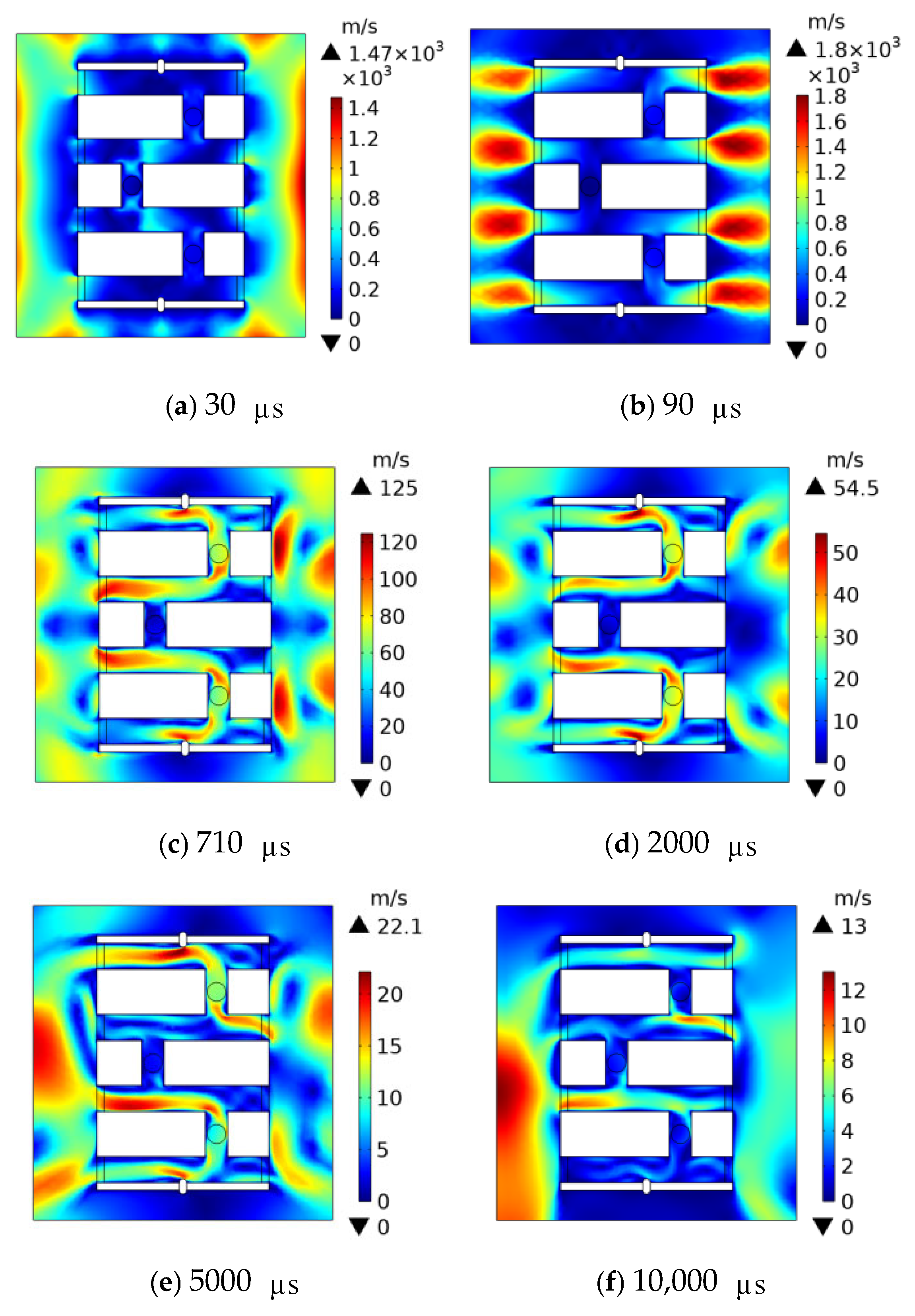
Figure 17 shows the velocity variation during the arc-extinguishing process with the participation of the electronegative gas C F 3 I . At 30 μ s , when the lightning flashover has just formed, the temperature rise inside the arc-extinguishing device is relatively slow. At this moment, some gas is discharged from the device at a small velocity. The continuous heat release from the arc causes the air to expand continuously and be discharged outward, so the velocity increases constantly, reaching a peak of over 1000 m/s at 90 μ s . After the lightning current disappears, the energy supply effect of the power frequency current is not significant, and the airflow velocity decreases continuously. When the arc is extinguished at 710 μ s , the maximum velocity is only 124 m/s, and when the power frequency current reaches 0 at 5000 μ s , the maximum velocity is 21.97 m/s. After 5000 μ s , the power frequency current begins to decrease gradually. However, because most of the high-energy particles have been carried away by the previous high-speed airflow and C F 3 I , the effect of the power frequency current is not obvious from 5000 μ s to 10,000 μ s . When the current reaches its maximum at 10,000 μ s , the velocity is only 12.43 m/s.

4. Conclusions

(1)
Based on the shortcomings in the field of lightning protection for 10 kV distribution lines, this study proposes a new type of arc-extinguishing lightning protection device with same-layer double break, and applies the environmentally friendly electronegative gas trifluoroiodomethane ( C F 3 I ) to lightning protection and arc extinguishing. Combined with the specifications of 10 kV lines, this paper reasonably sets the power frequency current for simulation and achieves a good arc-extinguishing effect.
(2)
Through analysis and simulation research on the arc-extinguishing device, this study reveals that when the horizontal distance of the compression channel is set to 9 mm, and the arc temperature exhibits the fastest cooling rate. Under this structural parameter, no flashover phenomenon is observed outside the device, and the arc-extinguishing performance of the device reaches an optimal state.
(3)
This study compares the arc-extinguishing performance of the proposed device under the action of power frequency currents with two different initial phases of π / 2 and 0. The simulation results indicate that the device can achieve arc extinction within 800 μ s , and no arc re-ignition phenomenon is observed in the subsequent monitoring period.
(4)
A systematic study was carried out on the arc-extinguishing process of the device using an environment-friendly electronegative gas (trifluoroiodomethane). The simulation results demonstrate that the arc is successfully extinguished within 710 μ s , and the arc-extinguishing time is shortened by 11.2% compared with the reference group. Meanwhile, the internal temperature of the device shows a decreasing trend in the initial stage of the arc-extinguishing process. Taking monitoring Point A inside the device as an example, under two different initial phases π / 2 and 0 of the power frequency current, the maximum temperature at this point decreases by 500 K and 1000 K, respectively. This significant temperature reduction effectively mitigates the risk of damage to the arc-extinguishing device caused by excessive internal pressure induced by high temperatures.

Author Contributions

Conceptualization, P.H. and Z.W.; methodology, Z.W.; software, Z.W.; validation, B.Z. and Z.W.; formal analysis, Y.L.; investigation, Y.L.; resources, P.H.; data curation, Z.W.; writing—original draft preparation, Z.W.; writing—review and editing, Z.W.; visualization, Z.L.; supervision, L.T.; project administration, Y.Z.; funding acquisition, P.H. All authors have read and agreed to the published version of the manuscript.

Funding

This research is funded by the National Natural Science Foundation of China “Research on the Mechanism of Extremely rapid Suppression of Flashover arcs in Overhead Transmission Lines Based on electronegative gases” (Grant NO:52467015).

Data Availability Statement

The original contributions presented in the study are included in the article; further inquiries can be directed to the corresponding author.

Conflicts of Interest

Li Tian is a employee of Wuzhou Bureau of Extra High Voltage Transmission Company. The paper reflects the views of the scientists and not the company.

References

  1. Hu, Y. Analysis and Prevention of Operational Faults in Transmission Lines. High Volt. Eng. 2007, 1–8. [Google Scholar] [CrossRef]
  2. Chen, J.; Zhao, C.; Gu, S.; Xiang, N.; Wang, Y.; Lei, M. Current Status and Development Trend of Lightning Monitoring and Protection Technology for Power Grids in China. High Volt. Eng. 2016, 42, 3361–3375. [Google Scholar] [CrossRef]
  3. Yang, J.; Yao, P.; Li, M.; Long, T.; He, W. Analysis and Countermeasures of Lightning Strike Accidents on Overhead Transmission Lines. Hunan Electr. Power 2019, 39, 23–25. [Google Scholar] [CrossRef]
  4. Zhao, C.; Ruan, J.; Li, X.; Xie, Y.; Huang, D.; Gu, S. Technical and Economic Evaluation of Comprehensive Lightning Protection Measures for Transmission Lines. High Volt. Eng. 2011, 37, 290–297. [Google Scholar] [CrossRef]
  5. He, J.; Zeng, R.; Chen, S. Research on Lightning Protection Technologies for Transmission Lines (III): Protection Measures. High Volt. Eng. 2009, 35, 2917–2923. [Google Scholar] [CrossRef]
  6. Chino, T.; Iwata, M.; Imoto, S.; Nakayama, M.; Sakamoto, H.; Matsushita, R. Development of arcing horn device for interrupting ground-fault current of 77 kV overhead lines. IEEE Trans. Power Deliv. 2005, 20, 2570–2575. [Google Scholar] [CrossRef]
  7. Podporkin, G.V.; Sivaev, A.D. Lightning protection of distribution lines by long flashover arresters (LFA). IEEE Trans. Power Deliv. 1998, 13, 814–823. [Google Scholar] [CrossRef]
  8. Li, Z.; Zhou, X.; Feng, Z.; Zhang, Y.; Wang, J. Mechanism and experimental study of arc suppression by polyphase longitudinal airflow. AIP Adv. 2021, 11, 105309. [Google Scholar] [CrossRef]
  9. Li, Z.; Wang, J.; Zhou, X.; Huang, S.; Yan, R.; Xia, Z. Influence of chamber structure on arc quenching in multigap system. High Volt. 2020, 5, 313–318. [Google Scholar] [CrossRef]
  10. Huang, P.; Wang, S.; Wang, G.F.; Wang, J.F.; Zheng, J.P. Study on lightning protection of collector line in wind farm by multi-fracture active arc extinguishing device. Electr. Power Syst. Res. 2022, 213, 108684. [Google Scholar] [CrossRef]
  11. Li, Q.; Wang, J.; Zhang, Y.; Wang, Y.; Chen, Y.; Yang, Z.; Tan, S.; Wang, X. Research on the Performance of Gas-Blown Arc-Extinguishing Devices Based on Magnetohydrodynamics Theory. Power Syst. Technol. 2022, 46, 2025–2031. [Google Scholar] [CrossRef]
  12. Peng, F.; Wang, J.; Zhang, Q.; Li, Z.; Xu, Y.; Wang, G.; Pang, Z. Optimization of Airflow Channel for Arc-Extinguishing Lightning Protection Gap with Jet Airflow. South. Power Syst. Technol. 2021, 15, 43–48. [Google Scholar] [CrossRef]
  13. Bi, J.; Wang, J. Study on the Causes and Countermeasures of High Lightning Trip-Out Rate on Electric Transmission Lines. Energies 2025, 18, 857. [Google Scholar] [CrossRef]
  14. Wang, J.F.; Huang, P.; Guo, W.; Wu, D.; Liu, Q.L. Research and application of a new jet stream arc extinguishing gap lightning protection device. Electr. Power Syst. Res. 2016, 139, 161–169. [Google Scholar] [CrossRef]
  15. Congzhen, X.; Yancheng, L.; Yan, D.; Xinhao, X.; Xihan, X.; Xiyang, C. Arc-Extinguishing Simulation of 35 kV Self-Detaching Lightning Protection Device Based on Magnetohydrodynamics. Electr. Power Eng. Technol. 2023, 42, 61–69. [Google Scholar] [CrossRef]
  16. Zhou, H.; Yang, T.; Luo, Y.; Yi, W.; Xie, Z.; Wang, R.; Dan, S. A Rapid Arc-Extinguishing Method for Integrated Lightning Protection Gaps Based on the Air-Blowing Principle. South. Power Syst. Technol. 2023, 17, 119–126. [Google Scholar] [CrossRef]
  17. Xiao, S.; Zhang, X.; Tang, J.; Liu, S. A review on SF6 substitute gases and research status of CF3I gases. Energy Rep. 2018, 4, 486–496. [Google Scholar] [CrossRef]
  18. Widger, P.; Haddad, A.; Griffiths, H. Breakdown performance of vacuum circuit breakers using alternative CF3I-CO2 insulation gas mixture. IEEE Trans. Dielectr. Electr. Insul. 2016, 23, 14–21. [Google Scholar] [CrossRef]
  19. Widger, P. Investigation into CF3I-CO2 Gas Mixtures for Insulation of Gas-Insulated Distribution Equipment. Doctoral Dissertation, Cardiff University, Cardiff, UK, 2014. [Google Scholar]
  20. Zhang, X.; Zhou, J.; Tang, J.; Xiao, S.; Zhang, M. Experimental Study on Partial Discharge Characteristics of CF3I/N2 Mixed Gas. High Volt. Eng. 2013, 39, 287–293. [Google Scholar] [CrossRef]
  21. Zhao, X. Study on Arc-Extinguishing and Insulating Properties of Environmentally Friendly Insulating Gas CF3I. Doctoral Dissertation, Shanghai Jiao Tong University, Shanghai, China, 2018. [Google Scholar] [CrossRef]
  22. Schlitz, L.Z.; Garimella, S.V.; Chan, S.H. Gas dynamics and electromagnetic processes in high-current arc plasmas. Part I. Model formulation and steady-state solutions. J. Appl. Phys. 1999, 85, 2540–2546. [Google Scholar] [CrossRef]
  23. Ghorui, S.; Heberlein, J.V.R.; Pfender, E. Thermodynamic and transport properties of two-temperature nitrogen-oxygen plasma. Plasma Chem. Plasma Process. 2008, 28, 553–582. [Google Scholar] [CrossRef]
  24. Fusheng, W.; Xiangteng, M.A.; Han, C. Evolution simulation of lightning discharge based on a magnetohydrodynamics method. Plasma Sci. Technol. 2018, 20, 075301. [Google Scholar] [CrossRef]
  25. Liao, M.; Wu, H.; Wang, C.; Xia, W. Discussion on Steenbeck’s Minimum Arc Voltage Principle in Arc Discharge. High Volt. Eng. 2018, 44, 926–931. [Google Scholar] [CrossRef]
  26. Li, Z.; Wang, J.; Zhang, H.; Dai, Q.; Feng, D. Research on the Mechanism of Arc-Extinguishing Lightning Protection Gaps Based on Multi-Point Truncation of Compressed Arcs. Insul. Surge Arresters 2017, 150–155+160. [Google Scholar] [CrossRef]
  27. Liao, M.R.; Li, H.; Xia, W.D. Approximate explicit analytic solution of the Elenbaas-Heller equation. J. Appl. Phys. 2016, 120, 063304. [Google Scholar] [CrossRef]
  28. Cong, H.; Li, Q.; Xing, J.; Li, J.; Chen, Q. A Calculation Method for Arcing Time of Induced Arcs Based on Energy Balance. Proc. CSEE 2015, 35, 3450–3458. [Google Scholar] [CrossRef]
  29. Zhang, X.; Dai, Q.; Han, Y.; Xiao, S. Study on Discharge Decomposition Components of CF3I Under Micro-Water Conditions. High Volt. Eng. 2016, 42, 172–178. [Google Scholar] [CrossRef]
  30. Huang, P.; Xu, S.; Qin, H.; Yang, G.; Huang, J.; Li, Z. Magnetohydrodynamic simulation and test of compression arc-extinguishing device under icing condition. AIP Adv. 2024, 14, 015337. [Google Scholar] [CrossRef]
  31. Sima, W.-X.; Jia, W.-B.; Yuan, T.; Xu, H.; Yang, M. Magnetohydrodynamic model of electric arc in multi-segment microporous structure and simulation of gas-blast arc extinguishing performance. High Volt. Eng. 2016, 42, 3376–3382. [Google Scholar] [CrossRef]
  32. Naghizadeh-Kashani, Y.; Cressault, Y.; Gleizes, A. Net emission coefficient of air thermal plasmas. J. Phys. D Appl. Phys. 2002, 35, 2925. [Google Scholar] [CrossRef]
  33. Yokomizu, Y.; Ochiai, R.; Matsumura, T. Electrical and thermal conductivities of high-temperature CO2–CF3I mixture and transient conductance of residual arc during its extinction process. J. Phys. D Appl. Phys. 2009, 42, 215204. [Google Scholar] [CrossRef]
  34. Cressault, Y.; Connord, V.; Hingana, H.; Teulet, P.; Gleizes, A. Transport properties of CF3I thermal plasmas mixed with CO2, air or N2 as an alternative to SF6 plasmas in high-voltage circuit breakers. J. Phys. D Appl. Phys. 2011, 44, 495202. [Google Scholar] [CrossRef]
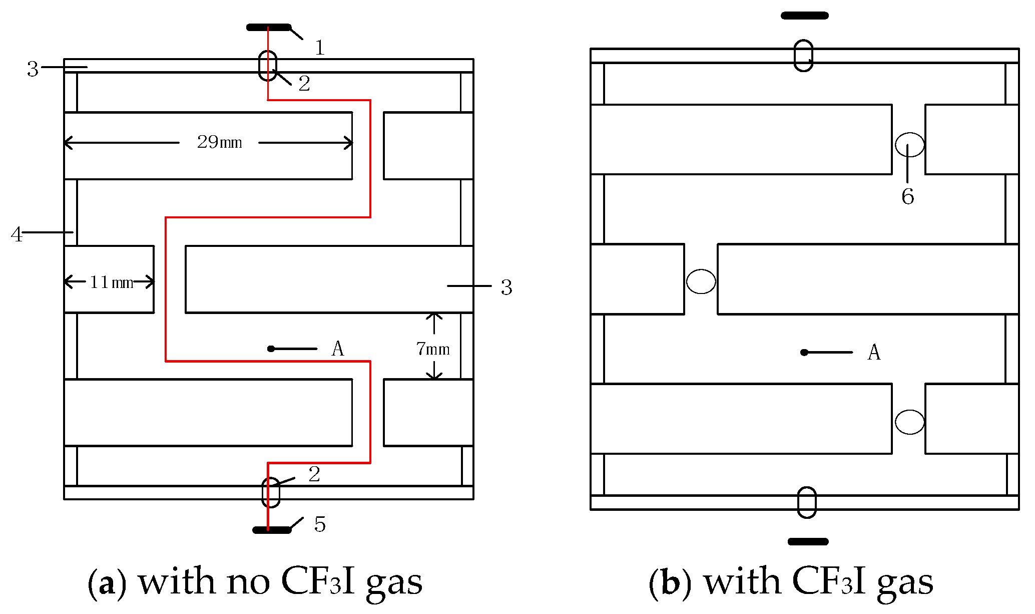
Figure 1. Two-dimensional schematic diagram of the device.
Plasma 08 00037 g001
Figure 2. Installation Schematic Diagram.
Plasma 08 00037 g002
Figure 3. Schematic diagram of self-magnetic compression.
Plasma 08 00037 g003
Figure 4. Schematic diagram of internal airflow arc blowing in the device.
Plasma 08 00037 g004
Figure 5. Mesh Generation Diagram.
Plasma 08 00037 g005
Figure 6. Comparison of Basic Parameters Between Air and C F 3 I .
Plasma 08 00037 g006
Figure 7. Temperature changes at point A for different distances.
Plasma 08 00037 g007
Figure 8. External flashover of lightning arc.
Plasma 08 00037 g008
Figure 9. Arc temperature changes at Point A during the arc-extinguishing process under power frequency currents with different initial phases.
Plasma 08 00037 g009
Figure 10. Diagram of Temperature Variation in the Arc-Extinguishing Process of Power Frequency Current with an Initial Phase of π / 2 .
Plasma 08 00037 g010
Figure 11. Diagram of Velocity Variation in the Arc-Extinguishing Process of Power Frequency Current with an Initial Phase of π / 2 .
Plasma 08 00037 g011
Figure 12. Diagram of Temperature Variation in the Arc-Extinguishing Process of Power Frequency Current with an Initial Phase of 0.
Plasma 08 00037 g012
Figure 13. Diagram of Velocity Variation in the Arc-Extinguishing Process of Power Frequency Current with an Initial Phase of 0.
Plasma 08 00037 g013
Figure 14. Temperature variation at Point A during the arc-extinguishing process.
Plasma 08 00037 g014
Figure 15. Average temperature variation in the device during the first 300 μ s of the arc-extinguishing process.
Plasma 08 00037 g015
Figure 16. Diagram of Temperature Variation in the Arc-Extinguishing Process with C F 3 I Participation.
Plasma 08 00037 g016
Figure 17. Diagram of Velocity Variation in the Arc-Extinguishing Process with C F 3 I Participation.
Plasma 08 00037 g017
Disclaimer/Publisher’s Note: The statements, opinions and data contained in all publications are solely those of the individual author(s) and contributor(s) and not of MDPI and/or the editor(s). MDPI and/or the editor(s) disclaim responsibility for any injury to people or property resulting from any ideas, methods, instructions or products referred to in the content.