Article

Inductive Medium Pressure UV-Source

Light Technology Institute, Karlsruhe Institute of Technology, Engesserstr. 13, 76131 Karlsruhe, Germany
*
Author to whom correspondence should be addressed.
Plasma 2020, 3(1), 1-9; https://doi.org/10.3390/plasma3010001
Submission received: 24 June 2019 / Revised: 12 August 2019 / Accepted: 29 October 2019 / Published: 31 December 2019

Abstract

:
In this paper, an efficient inductively coupled medium pressure source for ultraviolet radiation (UV-source) is demonstrated. The lamp was operated with powers up to 3 kW while the radiation and the coldest point temperature were measured. In addition, different coil geometries were investigated. Here a symmetrical and asymmetrical winding density were compared. Also the operation pressures and DC to radiation efficiencies are presented. In this work, an operation pressure of one atmosphere and an UV-efficiency (200–380 nm) of 15.5% was achieved. This is comparable to conventional medium pressure Hg-lamp technology. The main advantage of the presented inductive lamp is the electrodeless operation and therefore the longer service life, since an electrode failure is eliminated.

1. Introduction

In many areas of radiation generation the LED is on the rise. However, the LED is currently not suitable for all applications. If high intensity is needed, the high and medium pressure discharge continues to be the dominant technology. Especially for special applications, such as UV water treatment, where only wavelengths < 300 nm are desirable, gas discharge lamps are widely applied. Although the use of LEDs is possible here, there are still no LEDs with a high radiation intensity yield in the UV wavelength range. Compared to discharge lamps with several hundred watts radiation output, UV-LEDs with radiation output intensities between 1 and 10 mW can be found in [1]. Furthermore, the lifetime of the UV-LEDs has been quite limited so far. With a service life between 1000 and 3000 h (UVB: 280-315 nm and UVC: 200-280 nm emitting LEDs) thus offers no alternative to gas discharge lamps [1]. Therefore, we demonstrate an inductively coupled medium pressure UV-source. Inductively coupled plasmas (ICP) are ignited by a high-frequency alternating field. The optimal frequency for electrodeless induction lamps with internal stray field couplers is between 2 and 3 MHz [2]. In this frequency range, a high plasma efficiency as well as a high radiation efficiency can be achieved. Compared to lamps with electrodes, a significantly longer service life should be possible with inductively driven lamps. Derived from commercially available electrodeless lamps, the presented system can be assumed to have a service life of ≈ 60000 h [3]. So far, the commercialization of inductive medium pressure mercury plasma lamps has failed due to the need for efficient powerful electronic ballasts. Their development was primarily limited by the used transistors based on silicon (Si) semiconductors. However, it has already been demonstrated that efficient MHz inverters with high output power can be realized by using gallium nitride (GaN) [4] or silicon carbide (SiC) field-effect transistor (FETs) [5,6,7,8]. The influence of different packages and transistor technologies on the switching behaviour, the loss distribution and the efficiency were investigated in [8]. This resulted in three inverters with an output power of approximately 2.5 kW at 2.5 MHz . This power level and frequency, combined with a high efficiency, making this technology ideal for ICPs. Therefore, the inductive operation of a medium pressure mercury lamp is presented.

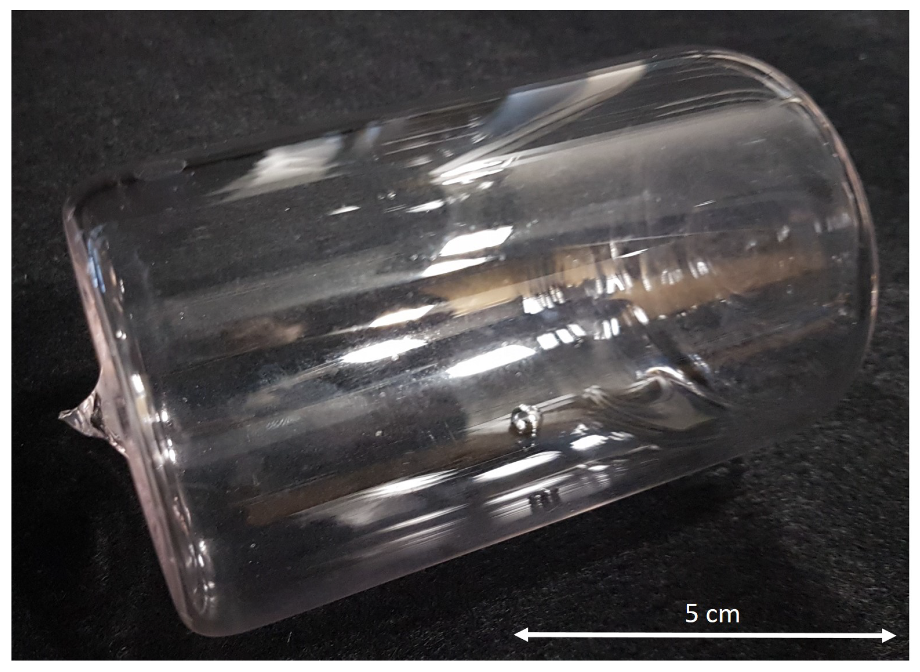
2. Lamp Geometry and Filling

The lamp vessel was made of quartz to ensure high transmittance for the UV radiation. A diameter of r = 65 mm was chosen under consideration of the influence of the radius to the needed ignition and maintenance fields, which has to be generated for a reliable ignition and stable operation [9,10]. For the lamp a length of l lamp = 100 mm was chosen.
The lamp vessel was evacuated to p 10 4 Pa and baked with a temperature of T 900 °C for eight hours to ensure clean and oxygen free surfaces. The clean vessel was filled with ≈ 1 g liquid Mercury under Argon atmosphere. This large amount was used to guarantee a saturated operation at any temperature condition. Due to the ignition behaviour, the Argon starting gas pressure was set to p = 30 Pa. The lamp vessel with the liquid Mercury filling is shown in Figure 1.

3. Electronic Ballast

According to [2], an excitation frequency between 2 and 3 MHz is necessary for the efficient operation of inductive lamps. It could be shown, by using SiC FETs, that high performance MHz inverters as electronic ballast are possible. Unfortunately the SiC FETs are usually offered in standard 3pin TO-247 packages. However, this package was developed for Si FETs, which are switching significantly slower. Only by using SiC FETs in new packages, which were optimized for fast switching, it is possible to achieve efficiencies above 90 % . In [8] the benefits of using the latest generation of SiC MOSFETs with novel packages are presented. Three types of MHz inverters with SiC MOSFETs were built and tested. The measurement results have shown that the realization of a compact and efficient resonant MHz inverter is possible with all three devices. However, the inverter with the Infineon SiC MOSFETs in 4pin TO-247 package (IMZ120R045M1) was able to achieve the best efficiency and is therefore used for the investigations presented here.

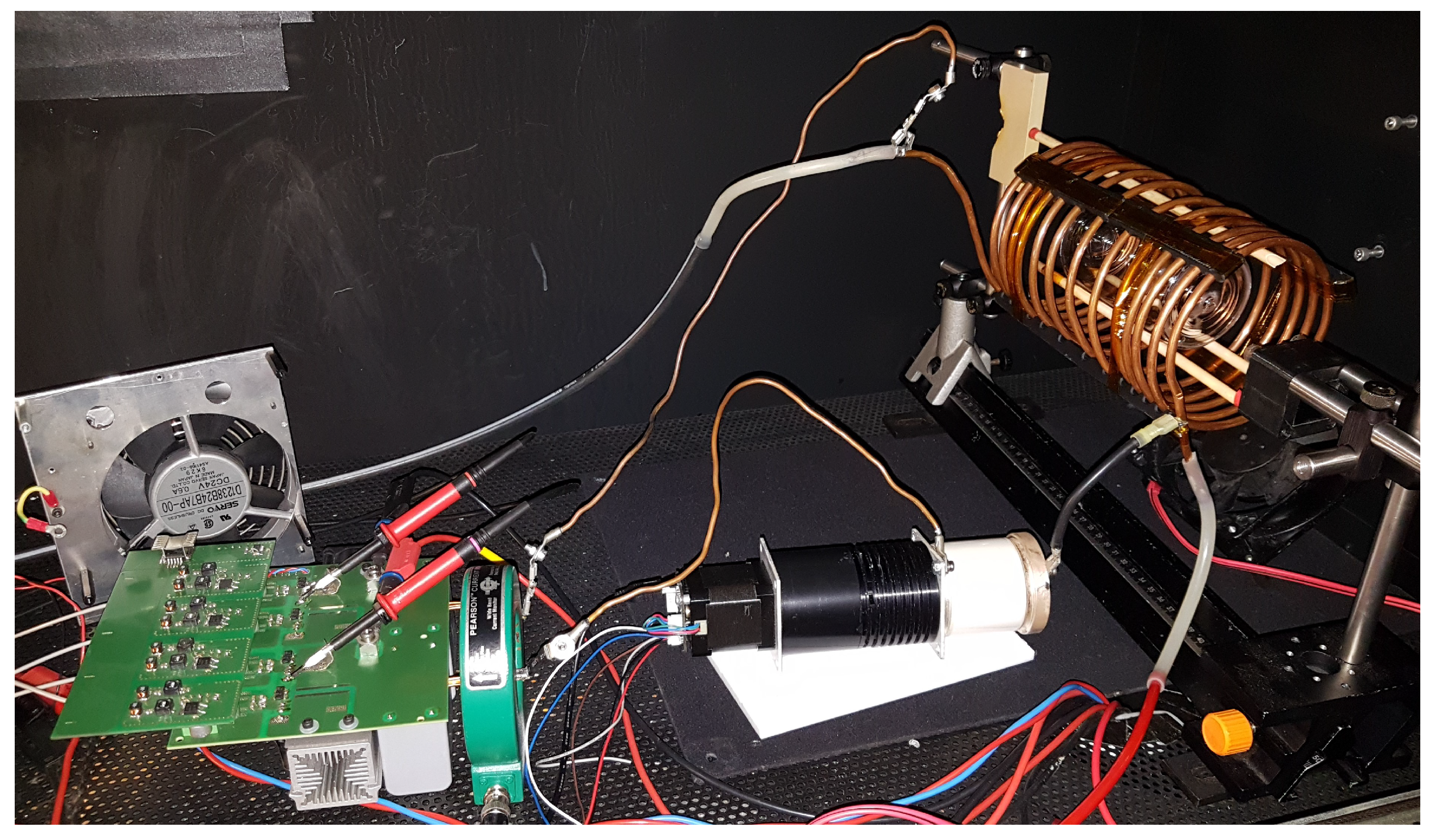
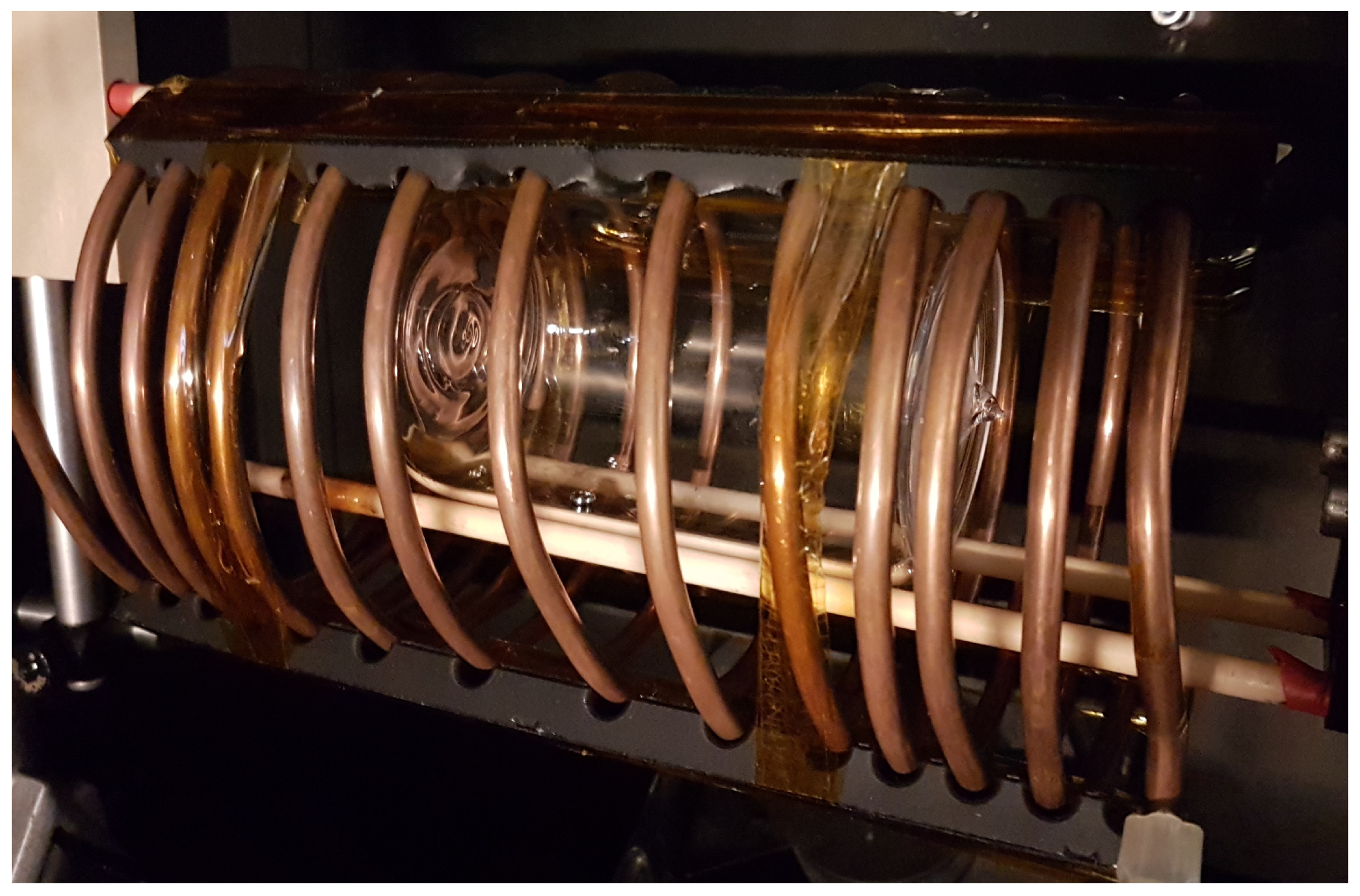
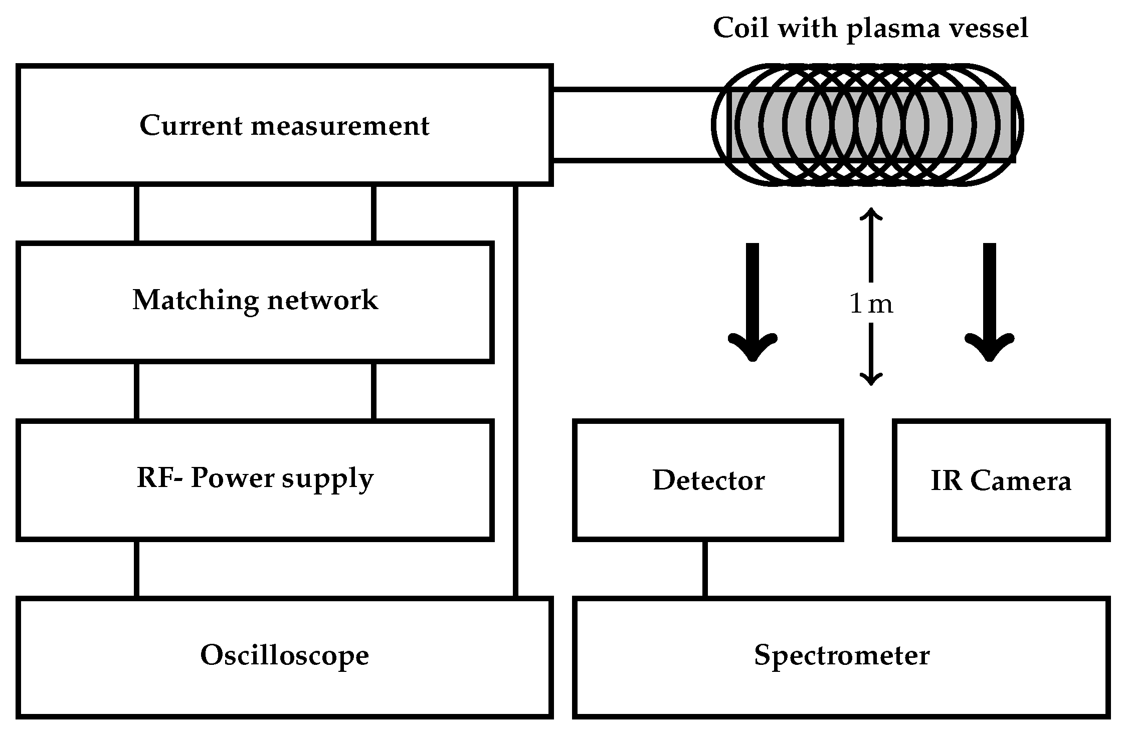
4. Experimental Setup

The inverter with the Infineon SiC MOSFETs in 4pin TO-247 package, presented in [8], is used to operate the inductive medium pressure lamp. The experimental setup is shown in Figure 2. The series resonant tank consists of the lamp coil and the capacitors on the inverter board. In addition, a variable vacuum capacitor with motor control was added in series to the lamp coil. The motor control can be used to compensate the detuning of the resonant tank by the impedance change of the plasma. The lamp coil was build out of 5 mm copper tube.
For the measurements, two different lamp coils were investigated, one with symmetrical (hereinafter referred to as symmetrical coil) and one with asymmetrical winding distribution (hereinafter referred to as asymmetrical coil). The asymmetrical winding was manufactured that the winding density in the area of the lamp is lower and thus the shading by the coil is reduced. The disadvantage is an asymmetrical field distribution and a higher production effort. The asymmetrical lamp coil including the lamp is shown in Figure 3. For the fixation of the windings, 3D printed fixations were used.
The parameters of both lamp coils are shown in Table 1. There the number of turns n, the length of the coil l, the coil diameter d, the inductance L, as well as the diameter of the copper tube d tube are given. The inductance L of the coils were measured by an Impedance Analyzer (4395A, Agilent Technologies, Santa Clara, CA, USA).
The spectral output of the lamp was measured between 200 and 800 nm by a calibrated array-spectrometer (CAS 140CT, Instrument Systems, Munich, Germany). The detector head was placed in a distance of 1 m from the lamp. To monitor the lamp temperature for the pressure calculation, an thermographic camera was used (A325, FLIR Systems, Wilsonville, OR, USA). The measurement setup is sketched in Figure 4. For the measurement, the lamp was ignited and the input power increased stepwise. At each measured power level, the lamp was operated until the temperature and the radiation output were in a stable condition.

5. Results and Discussion

Due to the fact that the used inverter and resonant tank need a defined coil inductance, two different maximal input power values were achieved. For the symmetrical coil a maximum input power of 3.4 kW was possible. Because of the lower inductance of the asymmetrical coil (see Table 1) only powers up to 1.5 kW could be realized. Up to that values the temperature and radiation output were monitored to discuss the efficiency and the pressure of the lamp.

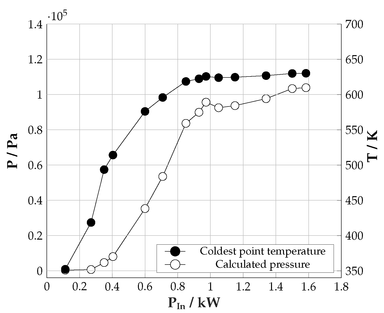
5.1. Temperature and Pressure

For the pressure calculation the temperature dependent vapour pressure of Mercury was used. In the lamp vessel the vapour pressure is defined by the temperature of the coldest point at the glass surface. In the measured temperature range, the vapour pressure can be calculated as [11]:
l o g 10 ( p / a t m ) = 3176 1 T + 5.048
This formula defines the saturation vapour pressure over the temperature. The assumption of a Mercury saturated discharge is justified due to the large filling amount. As shown in Figure 5, marked with the white circle, even at higher temperatures, a reservoir of liquid mercury was observed. The rise of the Argon pressure can be taken into account by using the ideal gas law. Therefore the neutral gas density is calculated at room temperature. This value is used to calculate the increase of the pressure during the temperature rise and then the sum over the partial pressures is build. The coldest point was assumed to be in the range of the liquid mercury reservoir (see Figure 5). The temperature measurement of the coldest point and the calculated pressure over the input power of the asymmetrical configuration is shown in Figure 6.
When the input power is further increased, the temperature reached a nearly constant value. This can be explained by the higher temperature gradient to the ambient air and the higher collision frequency in the plasma, which reduces the heat transfer from the plasma bulk to the wall. At the maximum glass surface temperature of ≈ 625 K a discharge pressure of one atmosphere was calculated. It must be noted that the outside of the glass vessel was regarded as the coldest point during this measurement. However, higher temperatures should prevail at the inner glass wall. For this reason, the given calculations are only approximations.

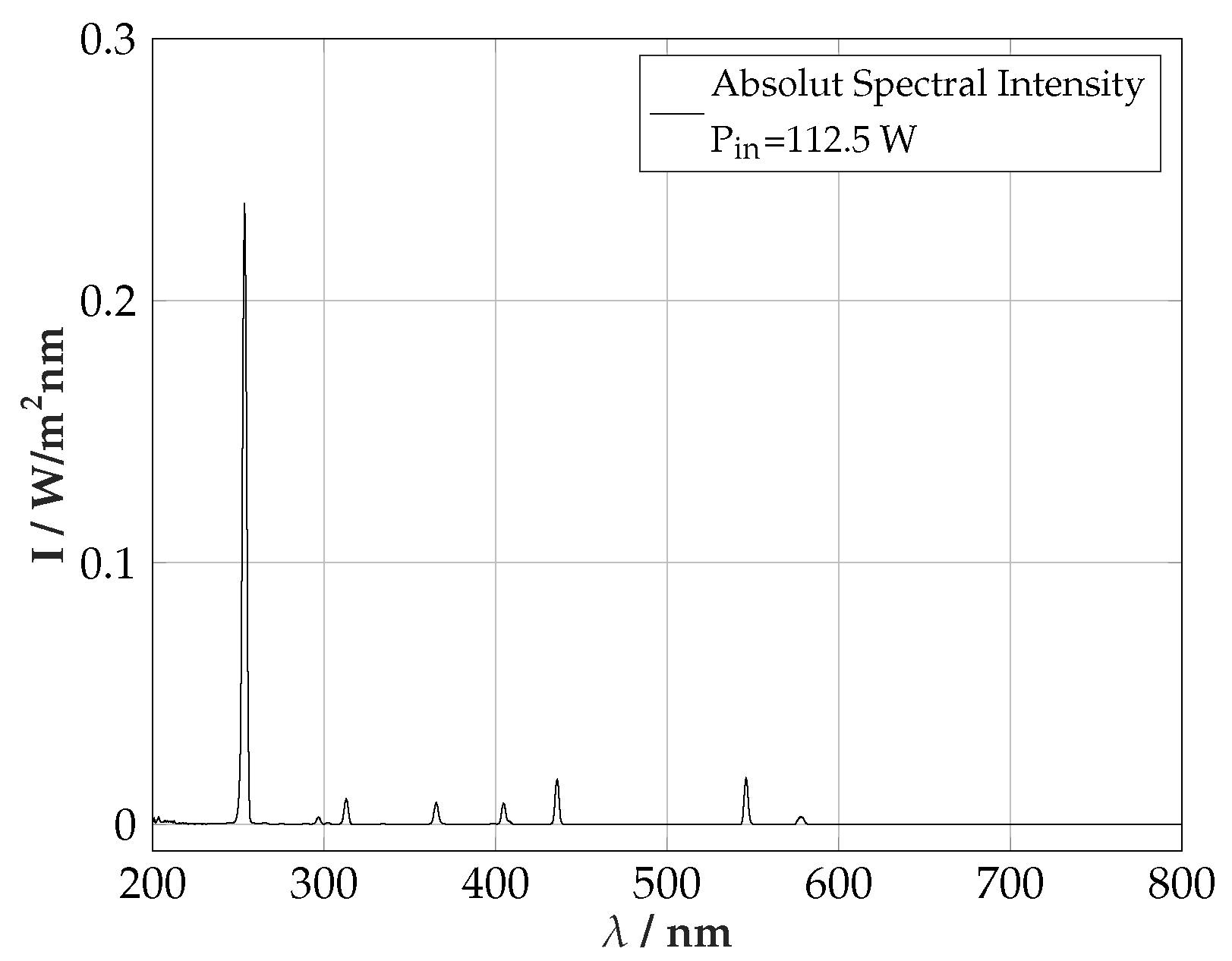
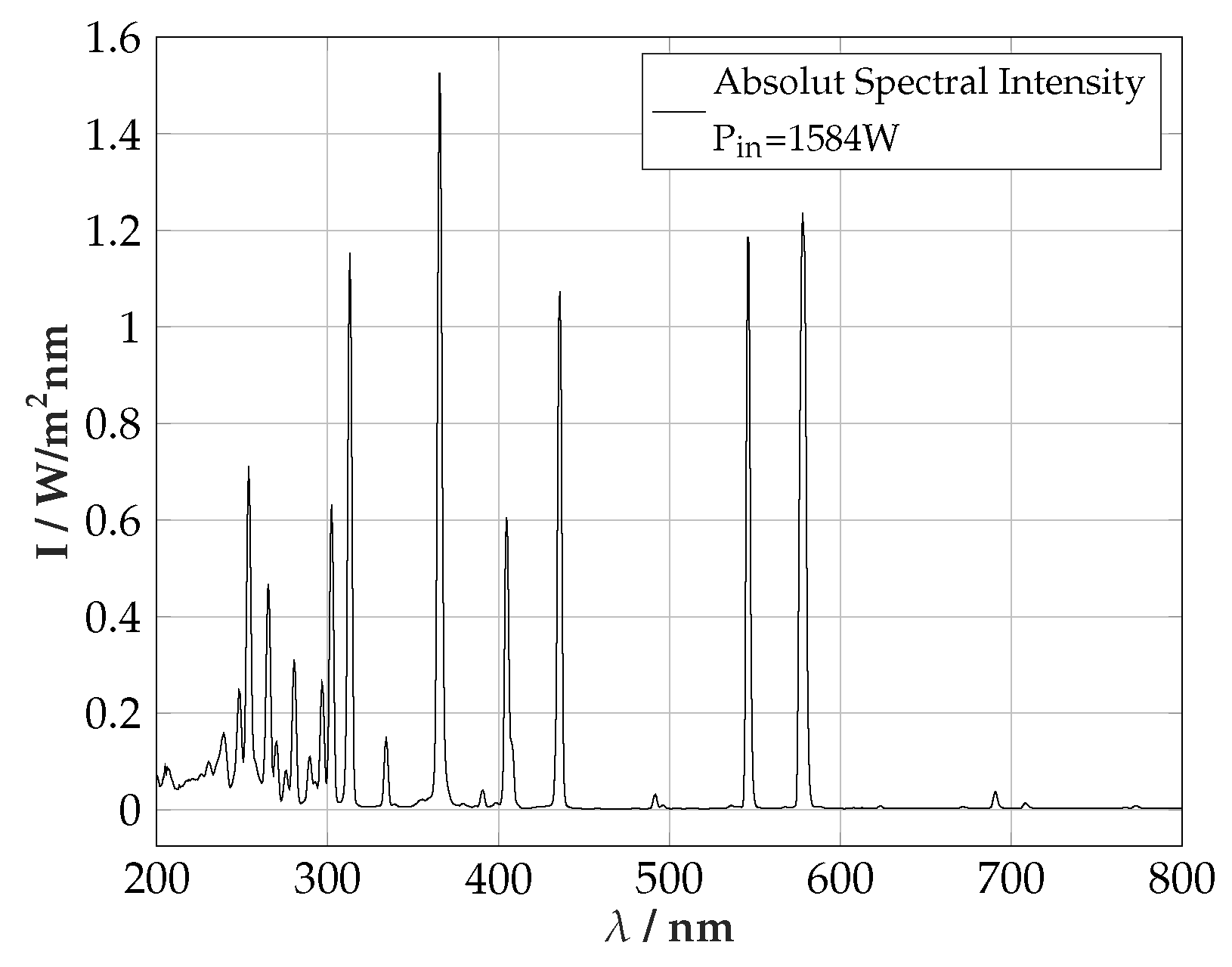
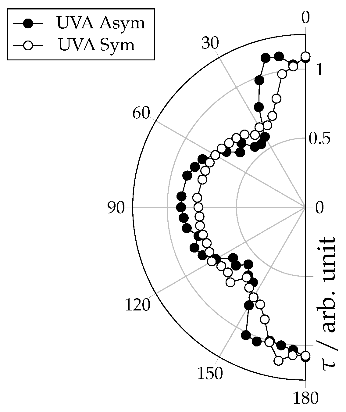
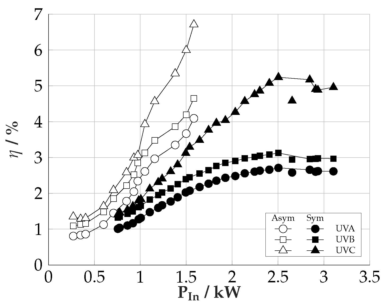
5.2. Spectral Output and Efficiency

At a low power input, a low pressure Mercury line spectra was observed, as shown in Figure 7. With a higher input power and therefore a higher temperature, the pressure is drastically increased, in accordance to the vapour pressure function given in Equation (1). With the higher pressure the spectral output is changing to a Mercury medium pressure spectrum as shown in Figure 8.
To simplify the comprehensibility of the following calculations, the nomenclature of the various intensities is shown in Table 2.
The radiation efficiency was calculated over a sphere by using:
η = 4 π d det 2 1 P in λ min λ max I ICP ( λ ) d λ
With the intensity I I C P = I I C P S or I I C P = I I C P A , the wavelength λ , the input power of the inverter P in and the detector distance d det . For the wavelength the ranges in Table 3 were used. Due to the chosen distance of d det = 1 m l lamp = 0.1 m the treatment of the lamp as a point-like source is suitable. However, this method is not completely accurate, because of the not spherical surface of the lamp and the shading by the windings. To justify the usage of Equation (2), the angular dependent transmission τ ( ϕ ) of the two coil types in ϕ = 5° steps were measured. Therefore, the detector was mounted in a distance of 1 m to the lamp surface on an angle adjustable disc with the rotation point at the centre of the lamp. The 90° angle was set perpendicular to the rotational axis of the lamp. The measurement then was done with a conventional lamp with and without the coils. The reference intensity without coil I ref is defined as:
I ref ( ϕ ) = λ min λ max I C O N ( λ ; ϕ ) d λ ϕ = 0 , 5 , 10 , . . . , 180 °
with Equation (4), the angular dependent transmission τ S ( ϕ ) for the symmetrical coil was calculated as:
τ S ( ϕ ) = 1 I ref ( ϕ ) λ min λ max I C O N S ( λ ; ϕ ) d λ I ref ( 90 ° ) ϕ = 0 , 5 , 10 , . . . , 180 °
The calculation of τ A ( ϕ ) for the asymmetrical coil was done analogously. As example for the results, in Figure 9 the UVA transmission for the two coil types is shown. Obviously, the radiation through the coils over a semicircle is not uniform. As example, at the front and the end of the coil a transmission of τ ( ϕ ) > 1 is generated. That can be explained by internal reflections on the copper surface at the inside of the coils. Because there is no shading at the end of the coil a transmission factor of 1 is generated. With additional intensity from reflections on the copper surface the value is increasing and a transmission factor > 1 is measured. To decrease the error by integrating the radiation over a whole sphere the shading factor Λ was introduced, which was defined as the mean value of τ ( ϕ ) . This factor then was multiplied to the efficiency calculation:
η = 4 π d det 2 Λ P in λ min λ max I I C P ( λ ) d λ
In Figure 10, the efficiency of the lamp in the two coil types is shown. The maximal efficiency values are given in Table 3. As one can see, the lamp in the symmetrical coil reaches a maximal UV efficiency between 200 and 380 nm in the range of P in 2526 W. In the asymmetrical coil the radiation output and therefore the efficiency is increasing up to the highest input power of P in 1580 W which was available with the given configuration. The overall UV efficiency was measured at 15.5%. To compare the results with conventional technologies, a medium pressure lamp with electrodes and the same lamp length at 500 W was measured. The efficiency was also calculated by the use of Equation (2). The electrode lamp was measured with a P in to UV efficiency between 200 and 380 nm of 12.3%. In the UVA range the lamp was measured with an efficiency of 2.7% in the symmetrical and 4.1% in the asymmetrical coil. Compared with the conventional lamp with an efficiency of 3.6%, only the lamp in the asymmetrical coil offers a benefit. However, radiation in the UVA range can also be generated with III-nitride UV-LEDs. In literature efficiencies between 2% and 3% are reported [1]. In the UVB range the lamp generates radiation with an efficiency of 3.1% in the symmetrical and 4.7% in the asymmetrical coil. Here also only the lamp in the asymmetrical coil delivers higher values as the conventional lamp, which was measured with 4.5%. UV-LEDs in the UVB range are reported with < 2% [1]. The greatest advantages of the presented system were achieved in the UVC. 5.2% with the symmetrical and 6.7% with the asymmetrical coil were measured. Compared with the conventional electrode lamp with 4.5% an increase of 2.2% was possible with the asymmetrical coil configuration. Also compared with UVC-LEDs, which are reported with efficiencies between 2 and 4% [12], the presented system provides a good alternative.

6. Conclusions

In this paper, the operation of an inductively driven medium pressure lamp was investigated. We measured the temperature and radiation output to calculate the operation pressure and the inverter input power to radiation efficiency. Furthermore, two different coil types, a symmetrical and an asymmetrical coil configuration were tested. The highest UV efficiency of 15.5% was measured with the asymmetrical one at an input power of P in ≈ 1584 W. The most efficient power to radiation efficiency was measured with 6.7% in the UVC range. That might be particularly interesting for applications, such as water treatment, because there are only wavelengths with λ < 315 nm can be used. Compared to the measured electrode lamp an increase of the efficiency of 3.2% was possible. Because of the behaviour of the lamp in the symmetrical coil it can be presumed that the maximum efficiency of the lamp in the asymmetrical coil will further increase with a higher input power. Therefore the setup has to be adapted to the lower inductance of the asymmetrical one. However, it was shown that the inductively driven Mercury lamp reached the efficiency of conventional technologies. The main advance is the electrodeless operation, because the electrodes are the main failure cause of conventional lamps. Therefore, a longer lamp lifespan is possible. Due to the increase of the efficiency and the service life of the inductive lamp, the presented inductively driven UV-source provides a good alternative to conventional technologies.

Author Contributions

All authors contributed to all aspects of this research project. All authors have read and agreed to the published version of the manuscript.

Funding

This research was funded in part by the European Union’s Horizon 2020 research and innovation programme under grant number 641702.

Conflicts of Interest

The authors declare no conflict of interest.

References

  1. Kneissl, M.; Rass, J. III-Nitride Ultraviolet Emitters; Springer International Publishing: Cham, Switzerland, 2016; Volume 227. [Google Scholar] [CrossRef]
  2. Popov, O.A. Efficient Light Source Based on a Inductive Ferrite-Free Discharge at Frequencies of 300–3000 kHz. Tech. Phys. 2007, 52, 751–758. [Google Scholar] [CrossRef]
  3. OSRAM. The High-Performance Electrodeless Fluorescent Lamp. Available online: https://www.osram.com/media/resource/HIRES/333886/554635/ENDURA-QUICKTRONIC-System-QT-ENDURA.pdf (accessed on 16 December 2019).
  4. Armbruster, C.; Hensel, A.; Wienhausen, A.H.; Kranzer, D. Application of GaN power transistors in a 2.5 MHz LLC DC/DC converter for compact and efficient power conversion. Eur. Conf. Power Electron. Appl. 2016, 1–7. [Google Scholar] [CrossRef]
  5. Denk, F.; Haehre, K.; Kling, R.; Heering, W. Investigations of SMPD SiC-MOSFET phase-leg modules for MHz inverters Keywords. In Proceedings of the 18th European Conference on Power Electronics and Applications, EPE-PEMC 2016 ECCE Europe, Karlsruhe, Germany, 5–9 September 2016. [Google Scholar]
  6. Denk, F.; Simon, C.; Heidinger, M.; Kling, R.; Heering, W. Compact highly efficient 3-kW MHz inverter based on SMT SiC MOSFETs. In Proceedings of the Power Conversion and Intelligent Motion Conference (PCIM Europe 2017), Nuremberg, Germany, 1 May 2017; pp. 16–18. [Google Scholar]
  7. Denk, F.; Haehre, K.; Simon, C.; Eizaguirre, S.; Heidinger, M.; Kling, R.; Heering, W. 25 kW High Power Resonant Inverter Operating at 2.5 MHz based on SiC SMD phase-leg modules. In Proceedings of the PCIM Europe 2018: International Exhibition and Conference for Power Electronics, Intelligent Motion, Renewable Energy and Energy Management, Nürnberg, Germany, 6–7 May 2018; pp. 1–7. [Google Scholar]
  8. Denk, F.; Haehre, K.; Simon, C.; Eizaguirre, S.; Heidinger, M.; Kling, R.; Heering, W. RDS(on) vs. inductance: Comparison of SiC MOSFETs in 7pin D2Pak and 4pin TO-247 and their benefits for high power MHz inverters. IET Power Electron. 2019, 8. [Google Scholar] [CrossRef]
  9. Burm, K.T.A.L. Breakdown minimum in magnetic field-driven metal plasmas. J. Plasma Phys. 2011, 77, 675–678. [Google Scholar] [CrossRef]
  10. Kortshagen, U.; Gibson, N.D.; Lawler, J.E. On the E–H mode transition in RF inductive discharges. J. Phys. D Appl. Phys. 1996, 1996, 1224–1236. [Google Scholar] [CrossRef]
  11. Hansen, S.; Getchius, J.; Steward, R.; Brumleve, T. Vapor Pressure of Metal Bromides and Iodides: With Selected Metal Chlorides and Metals, 2nd ed.; APL Engineered Materials, Inc.: Urbana, IL, USA, 2006. [Google Scholar]
  12. Chen, J.; Loeb, S.; Kim, J.H. LED revolution: Fundamentals and prospects for UV disinfection applications. Environ. Sci. Water Res. Technol. 2017, 3, 188–202. [Google Scholar] [CrossRef]
Figure 1. Lamp vessel with liquid Mercury filling.
Plasma 03 00001 g001
Figure 2. Experimental setup for the lamp operation with the MHz-Inverter (left), the tunable capacitor (middle) and the coil (right).
Plasma 03 00001 g002
Figure 3. Lamp vessel placed inside the asymmetrical coil.
Plasma 03 00001 g003
Figure 4. Sketch of the used measurement setup.
Plasma 03 00001 g004
Figure 5. Liquid Mercury reservoir during operation at the maximal reached temperature of ≈ 625 K.
Plasma 03 00001 g005
Figure 6. Measured temperature and calculated pressure dependent on the input power.
Plasma 03 00001 g006
Figure 7. Measured low pressure line spectra of the lamp in the asymmetrical coil at 112.5 W input power.
Plasma 03 00001 g007
Figure 8. Measured medium-pressure spectra of the lamp in the asymmetrical coil at the most efficient point at 1584 W input power.
Plasma 03 00001 g008
Figure 9. Angular dependent UVA transmission τ of the asymmetrical (Asym) and symmetrical (Sym) coil.
Plasma 03 00001 g009
Figure 10. UVA, UVB and UVC efficiency of the lamp in the asymmetrical (Asym) and symmetrical (Sym) coil over the inverter input power.
Plasma 03 00001 g010
Table 1. Parameter for the symmetrical and asymmetrical coil configuration.
nldL d tube
symmetrical17 15 cm 9 cm 12.38 μ H 5 mm
asymmetrical13 19 cm 11 cm 8.67 μ H 5 mm
Table 2. Nomenclature of the intensities for the calculations.
NomenclatureMeaning
I I C P Intensity of the ICP lamp
I I C P S Intensity of the ICP lamp in the symmetrical coil
I I C P A Intensity of the ICP lamp in the asymmetrical coil
I C O N Intensity of the conventional lamp without coil
I C O N S Intensity of the conventional lamp in the symmetrical coil
I C O N A Intensity of the conventional lamp in the asymmetrical coil
Table 3. UV wavelength and highest measured efficiencies.
λ min λ max Reference lampSymmetrical CoilAsymmetrical Coil
η max   P in  = 500 W η max   P in  = 2526 W η max   P in  = 1548 W
UVA 315 nm 380 nm 3.6%2.7%4.1%
UVB 280 nm 315 nm 3.9%3.1%4.7%
UVC 200 nm 280 nm 4.5%5.2%6.7%
∑ UV 200 nm 380 nm 12.3%10.9%15.5%

